EP2210561A1 - Filter and x-ray imaging system - Google Patents
Filter and x-ray imaging system Download PDFInfo
- Publication number
- EP2210561A1 EP2210561A1 EP10150923A EP10150923A EP2210561A1 EP 2210561 A1 EP2210561 A1 EP 2210561A1 EP 10150923 A EP10150923 A EP 10150923A EP 10150923 A EP10150923 A EP 10150923A EP 2210561 A1 EP2210561 A1 EP 2210561A1
- Authority
- EP
- European Patent Office
- Prior art keywords
- filter
- plates
- support plate
- aperture
- filter plates
- Prior art date
- Legal status (The legal status is an assumption and is not a legal conclusion. Google has not performed a legal analysis and makes no representation as to the accuracy of the status listed.)
- Granted
Links
Images







Classifications
-
- A—HUMAN NECESSITIES
- A61—MEDICAL OR VETERINARY SCIENCE; HYGIENE
- A61B—DIAGNOSIS; SURGERY; IDENTIFICATION
- A61B6/00—Apparatus or devices for radiation diagnosis; Apparatus or devices for radiation diagnosis combined with radiation therapy equipment
- A61B6/06—Diaphragms
-
- G—PHYSICS
- G21—NUCLEAR PHYSICS; NUCLEAR ENGINEERING
- G21K—HANDLING OF PARTICLES OR IONISING RADIATION NOT OTHERWISE PROVIDED FOR; IRRADIATION DEVICES; GAMMA RAY OR X-RAY MICROSCOPES
- G21K1/00—Arrangements for handling particles or ionising radiation, e.g. focusing or moderating
- G21K1/02—Arrangements for handling particles or ionising radiation, e.g. focusing or moderating using diaphragms, collimators
- G21K1/025—Arrangements for handling particles or ionising radiation, e.g. focusing or moderating using diaphragms, collimators using multiple collimators, e.g. Bucky screens; other devices for eliminating undesired or dispersed radiation
-
- G—PHYSICS
- G21—NUCLEAR PHYSICS; NUCLEAR ENGINEERING
- G21K—HANDLING OF PARTICLES OR IONISING RADIATION NOT OTHERWISE PROVIDED FOR; IRRADIATION DEVICES; GAMMA RAY OR X-RAY MICROSCOPES
- G21K1/00—Arrangements for handling particles or ionising radiation, e.g. focusing or moderating
- G21K1/10—Scattering devices; Absorbing devices; Ionising radiation filters
Definitions
- the present invention relates generally to a filter and an X-ray imaging system. Particularly, the present invention is concerned with a filter for adjusting the spectrum of X-ray and an X-ray imaging system provided with such a filter.
- the spectrum of X-ray is adjusted by a filter and thereafter the X-ray is radiated to a subject.
- the filter is installed within a collimator box attached to an X-ray tube.
- plural filter plates of the filter which are attached to a rotary disc, are used selectively (see, for example, Japanese Unexamined Patent Publication No. Hei 11 (1999)-76219 (Paragraph No. 0009, Figs. 1 and 2 )).
- the spectrum be adjustable in multiple stages.
- the adjustment is up to four stages at most. If an attempt is made to make adjustment possible in seven or more multiple stages in the rotary disc method, the rotary disc for the mounting of many filters becomes large-sized and thus such an attempt is not practical.
- a filter for adjusting the spectrum of passing radiation comprising: a support plate having an aperture for passage therethrough of radiation; a plurality of filter plates supported by the support plate and having mutually different filer characteristics; and moving means for moving the plural filter plates selectively to a position to close the aperture and a position to open the aperture.
- a filter wherein the moving means comprises: spring means for operating the filter plates in a direction away from the aperture; a plurality of ratchets plates supported by the support plate in proximity to the filter plates and each having a notched portion; a first support point for supporting the filter plates pivotably on the support plate; a second support plate for supporting the ratchet plates pivotably on the support plate; a leaf spring connected to the filter plates and the ratchet plates, causing the filter plates and the ratchet plates to pivot interlockedly with each other; and a pawl engageable with the notched portions of the ratchet plates, the pawl being moved to pivot the ratchet plates, thereby making the filter plates movable to the position to close the aperture.
- a filter wherein the support plate has a top layer and a bottom layer parallel to each other, and the filter plates are supported by the top layer and the bottom layer.
- a filter wherein the support plate is in the shape of disc and is formed with the apertures at a center thereof.
- a filter further comprising a ring capable of rotating along the circumference of the support plate, and the pawl is provided in the ring.
- an X-ray imaging system for radiographing a subject with X-ray passing through a filter
- the filter comprising: a support plate having an aperture for passage therethrough of radiation; a plurality of filter plates supported by the support plate and having mutually different filter characteristics; and moving means for moving the plural filter plates selectively to a position to close the aperture and a position to open the aperture.
- an X-ray imaging system wherein the moving means comprises: spring means for operating the filter plates in a direction away from the aperture; a plurality of ratchet plates supported by the support plate in proximity to the filter plates and each having a notched portion; a first support point for supporting the filter plates pivotably on the support plate; a second support point for supporting the ratchet plates pivotably on the support plate; a leaf spring connected to the filter plates and the ratchet plates, causing the filter plates and the ratchet plates to pivot interlockedly with each other; and a pawl engageable with the notched portions of the ratchet plates, the pawl being moved to pivot the ratchet plates, thereby making the filter plates movable to the position to close the aperture.
- an X-ray imaging system wherein the support plate has a top layer and a bottom layer parallel to each other, and the filter plates are supported by the top layer and the bottom layer.
- an X-ray imaging system wherein the support plate is in the shape of a disc and is formed with the aperture at a center thereof.
- an X-ray imaging system wherein the filter further comprises a ring capable of rotating along the circumference of the support plate, and the pawl is provided in the ring.
- the filter for adjusting the spectrum of passing radiation comprises: a support plate having an aperture for passage therethrough of radiation; a plurality of filter plates supported by the support plate and having mutually different filter characteristics; and moving means for moving the plural filter plates selectively to a position to close the aperture and a position to open the aperture, it is possible to realize a filter capable of adjusting the spectrum in multiple stages and capable of attaining the reduction of size, as well as an X-ray imaging system provided with such a filter.
- Fig. 1 shows a schematic configuration of an X-ray imaging system.
- This system is an example of the preferred mode for carrying out the invention. With the configuration of this system there is shown an example of the preferred mode for carrying out the invention with respect to the X-ray imaging system.
- this system includes an X-ray irradiator 10, an X-ray detector 20 and an operator console 30.
- the X-ray irradiator 10 and the X-ray detector 20 are opposed to each other with a subject 40 therebetween.
- the X-ray irradiator 10 includes an X-ray tube 12 and a collimator box 14.
- a filter 16 and a collimator 18 are accommodated within the collimator box 14.
- the filter 16 is an example of the preferred mode for carrying out the invention. With the configuration of the filter 16 there is shown an example of the preferred mode for carrying out the invention with respect to the filter.
- X-ray emitted from the X-ray tube 12 is adjusted its spectrum by the filter 16 and is then radiated to the subject 40 through an aperture of the collimator 18.
- the filter 16 is a spectrum variable filter.
- the collimator 18 is an aperture variable collimator.
- the X-ray which has passed through the subject 40 is detected by the X-ray detector 20 and is inputted to the operator console 30.
- the operator console 30 reconstructs a radioscopic image of the subject 40.
- the reconstructed image is displayed on a display 32 of the operator console 30.
- the operator console 30 controls the X-ray irradiator 10. Control of the filer 16 and that of the collimator 18 are included in the control of the X-ray irradiator 10 made by the operator console 30. Where required, the filter 16 and the collimator 18 can be adjusted manually.
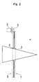
- Fig. 2 shows the configuration of the filter 16 schematically.
- the filter 16 is of a two-layer structure comprising a top layer 100 and a bottom layer 200.
- the top layer 100 has an aperture 102 and the bottom layer 200 has an aperture 202.
- the apertures 102 and 202 are concentric and equal in size and X-ray passes through the apertures 102 and 202.
- the top layer 100 and the bottom layer 200 each have on the outer periphery thereof such a ring as will be described later.
- the rings are integrally driven by a motor 300 via a gear 302 so as to be rotatable reversibly in clockwise and counterclockwise directions.
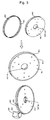
- Fig. 3 shows a ring-detached state and a ring-attached state with respect to the top layer 100 and the bottom layer 200.
- the top layer 100 and the bottom layer 200 include disc-like top support 104 and bottom support 204 assembled together in facing relation to each other, as well as rings 106 and 206 attached respectively to their outer peripheries in a rotatable manner.
- the top support 104 and the bottom support 204 do not rotate and are formed with the apertures 102 and 202 respectively at their centers.
- the rings 106 and 206 are integrally driven by the motor 300 via the gear 302 and are adapted to rotate along the circumference of the top support 104 and that of the bottom support 204 respectively.
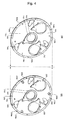
- Fig. 4 shows a disassembled state of the filter 16 into the top layer 100 and the bottom layer 200.
- Fig. 4 shows a state in which the top support 104 and the bottom support 204 are opened to both right and left at the confronting portion thereof.
- the top support 104 and the bottom support 204 are coupled together by three holes 108a, 108b, 108c formed in the top support 104 and three studs 208a, 208b, 208c formed on the bottom support 104.
- the rings 106 and 206 are coupled together by three holes 109a, 109b, 109c formed in the ring 106 and three studs 209a, 209b, 209c formed on the ring 206.
- the top support 104 has three filter plates 110, 120 and 130 on an inner surface thereof, i.e., on its surface confronting the bottom support 204.
- the filter plates 110, 120 and 130 comprise three steel plates or the like different in thickness and supported by a support frame.
- the three steel plates or the like are 0.1, 0.2 and 0.3 mm, respectively, in thickness.
- the filter plates 110, 120 and 130 constitute a part of three parallel link mechanisms, and with operation of the parallel links, the filter plates are adapted to advance and retreat to a position to close the aperture 120 and a position to open the same aperture.
- the three parallel links are driven in order by a pawl 140 which rotates together with the ring 106.
- a pawl 140 which rotates together with the ring 106.
- the filter plate 110 has advanced to the position to close the aperture 102, while the filter plates 120 and 130 have retreated to the position to open the aperture 102.
- the bottom support 204 has three filter plates 210, 220 and 230 on an inner surface thereof, i.e., on its surface confronting the top support 104.
- the filter plates 210, 220 and 230 comprise three steel plates or the like different in thickness and supported by a support frame.
- the three steel plates or the like are 0.6, 0.9 and 1.5 mm, respectively, in thickness.
- the filter plates 210, 220 and 230 constitute a part of the three parallel links, and with operation of the parallel links, the filter plates are adapted to advance and retreat to a position to close the aperture 202 and a position to open the same aperture.
- the three parallel links are driven in order by a pawl 240 which rotates together with the ring 206.
- a pawl 240 which rotates together with the ring 206.
- the filter plate 210 has advanced to the position to close the aperture 202, while the filter plates 220 and 230 have advanced to the position to open the aperture 202.
- Fig. 5 shows the configuration and operation of parallel links with respect to the filter plate 110. Also as to the other filter plates 120 to 230, the configuration and operation of parallel links are the same. As shown in Fig. 5 , the parallel links are made up of links A, B, C, D and joints a, b, c, d.
- the link A is a fixed link
- the link B is a driving link
- the link C is a parallel moving link
- the link D is a driven link.
- the driven link D is constituted by the filter plate 110 and the driving link B is constituted by a ratchet plate 112.
- the filter plate 110 is rotatable about the joint a
- the ratchet plate 112 is rotatable about the joint b, and both are connected together at the joints c and d through the link C.
- the filter plate 110 assumes either such a retreated state as Fig. 5(a) or such an advanced state as Fig. 5(b) .
- the filter plate 110 in its retreated state Fig. 5(a) , opens the aperture 102, while in its advanced state Fig. 5(b) it closes the aperture 102.
- a tensile force induced by a spring 114 acts on the filter plate 110 constantly. Consequently, while the parallel links are not in operation, the filter plate 110 is in abutment against a stop pin 116, as shown in Fig. 6(a) .
- the parallel links operate when the ratchet plate 112 is pushed up by the pawl 140.
- the pawl 140 rotates while describing a circular path together with the ring 106 and pushes up the ratchet plate 112 when it rotates in the counterclockwise direction, thereby causing rotation of the ratchet plate 112.
- the parallel links operate and the filter plate 110 advances to the position to close the aperture 102, as shown in Fig. 6(b) .
- the engagement between the ratchet plate 112 and the pawl 140 in this state is as shown on a larger scale in Fig. 6(c) .
- the pawl 140 is attached to the ring 106 rotatably with a shaft 142.
- a rotating force is applied in the counterclockwise direction in the figure by means of a coil spring 144 mounted on the shaft 142 and the pawl 140 is in an abutted state against a stop pin 146.
- One end of the coil spring 144 is fixed to the pawl 140 and an opposite end thereof is fixed to a pin 148.
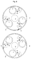
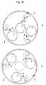
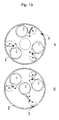
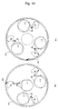
- Figs. 8 to 14 are diagrams in which the top layer 100 and the bottom layer 200 are seen in an X-ray irradiating direction.
- Fig. 8 shows an initial state of both top layer 100 and bottom layer 200. In the initial state, none of the filter plates close the apertures 102 and 202. This corresponds to the state in which a filter plate having a thickness of zero has been inserted into the apertures 102 and 202.
- filter plates 0.1, 0.2 and 0.3 located on the top player 100 side advance in order to the position to close the aperture 102, as shown in Figs. 9 , 10 and 11 .
- X-ray spectrum is adjusted by each of the filter plates.
- all the filter plates stay in their retreated positions because the pawl 240 passes while stroking all the ratchet plates.
- filter plates 0.6, 0.9 and 1.5 located on the bottom layer 200 side advance in order to the position to close the aperture 202, as shown in Figs. 12 , 13 and 14 .
- X-ray spectrum is adjusted by each of the filter plates.
- all the filter plates stay in their retreated positions because the pawl 140 passes while stroking all the ratchet plates.
- the filter 16 has a two-layer structure of both top layer 100 and bottom layer 200, and each layer has three filter plates driven by parallel links, thus facilitating reduction of the entire size.
- Two pawls for actuating parallel links may be provided for each layer as in Fig. 15 . With two pawls, it is possible to shorten the time for access to the filter plate located at the remotest position from the current position of each pawl.
- the filter 16 may be of a single-layer structure of either the top layer 100 or the bottom layer 200. Further, the number of filter plates per layer is not limited to three, but may be any other suitable number.
Landscapes
- Physics & Mathematics (AREA)
- Engineering & Computer Science (AREA)
- High Energy & Nuclear Physics (AREA)
- Health & Medical Sciences (AREA)
- Life Sciences & Earth Sciences (AREA)
- Medical Informatics (AREA)
- Spectroscopy & Molecular Physics (AREA)
- General Engineering & Computer Science (AREA)
- Optics & Photonics (AREA)
- Molecular Biology (AREA)
- Biophysics (AREA)
- Pathology (AREA)
- Radiology & Medical Imaging (AREA)
- Biomedical Technology (AREA)
- Heart & Thoracic Surgery (AREA)
- Nuclear Medicine, Radiotherapy & Molecular Imaging (AREA)
- Surgery (AREA)
- Animal Behavior & Ethology (AREA)
- General Health & Medical Sciences (AREA)
- Public Health (AREA)
- Veterinary Medicine (AREA)
- Apparatus For Radiation Diagnosis (AREA)
- Radiation-Therapy Devices (AREA)
Abstract
Description
- The present invention relates generally to a filter and an X-ray imaging system. Particularly, the present invention is concerned with a filter for adjusting the spectrum of X-ray and an X-ray imaging system provided with such a filter.
- In an X-ray imaging system, the spectrum of X-ray is adjusted by a filter and thereafter the X-ray is radiated to a subject. The filter is installed within a collimator box attached to an X-ray tube. In order to obtain a desired spectrum, plural filter plates of the filter, which are attached to a rotary disc, are used selectively (see, for example, Japanese Unexamined Patent Publication No.
Hei 11 (1999)-76219 Figs. 1 and2 )). - It is desirable that the spectrum be adjustable in multiple stages. However, in the configuration wherein filter plates are switched over from one to another by means of a rotary disc, the adjustment is up to four stages at most. If an attempt is made to make adjustment possible in seven or more multiple stages in the rotary disc method, the rotary disc for the mounting of many filters becomes large-sized and thus such an attempt is not practical.
- Accordingly, it is an object of the present invention to provide a filter permitting the adjustment of spectrum in multiple stages and that permitting the reduction of size, as well as an X-ray imaging system provided with such a filter.
- In a first aspect of the present invention as means for addressing the above-mentioned problem there is provided a filter for adjusting the spectrum of passing radiation, comprising: a support plate having an aperture for passage therethrough of radiation; a plurality of filter plates supported by the support plate and having mutually different filer characteristics; and moving means for moving the plural filter plates selectively to a position to close the aperture and a position to open the aperture.
- In a second aspect of the present invention as means for addressing the above-mentioned problem there is provided, in accordance with the first aspect, a filter wherein the moving means comprises: spring means for operating the filter plates in a direction away from the aperture; a plurality of ratchets plates supported by the support plate in proximity to the filter plates and each having a notched portion; a first support point for supporting the filter plates pivotably on the support plate; a second support plate for supporting the ratchet plates pivotably on the support plate; a leaf spring connected to the filter plates and the ratchet plates, causing the filter plates and the ratchet plates to pivot interlockedly with each other; and a pawl engageable with the notched portions of the ratchet plates, the pawl being moved to pivot the ratchet plates, thereby making the filter plates movable to the position to close the aperture.
- In a third aspect of the present invention as means for addressing the above-mentioned problem there is provided, in accordance with the first aspect, a filter wherein the support plate has a top layer and a bottom layer parallel to each other, and the filter plates are supported by the top layer and the bottom layer.
- In a fourth aspect of the present invention as means for addressing the above-mentioned problem there is provided, in accordance with any of the first to the third aspects, a filter wherein the support plate is in the shape of disc and is formed with the apertures at a center thereof.
- In a fifth aspect of the present invention as means for addressing the above-mentioned problem there is provided, in accordance with any of the first to the fourth aspects, a filter further comprising a ring capable of rotating along the circumference of the support plate, and the pawl is provided in the ring.
- In a sixth aspect of the present invention as means for addressing the above-mentioned problem there is provided an X-ray imaging system for radiographing a subject with X-ray passing through a filter, the filter comprising: a support plate having an aperture for passage therethrough of radiation; a plurality of filter plates supported by the support plate and having mutually different filter characteristics; and moving means for moving the plural filter plates selectively to a position to close the aperture and a position to open the aperture.
- In a seventh aspect of the present invention as means for addressing the above-mentioned problem there is provided, in accordance with the sixth aspect, an X-ray imaging system wherein the moving means comprises: spring means for operating the filter plates in a direction away from the aperture; a plurality of ratchet plates supported by the support plate in proximity to the filter plates and each having a notched portion; a first support point for supporting the filter plates pivotably on the support plate; a second support point for supporting the ratchet plates pivotably on the support plate; a leaf spring connected to the filter plates and the ratchet plates, causing the filter plates and the ratchet plates to pivot interlockedly with each other; and a pawl engageable with the notched portions of the ratchet plates, the pawl being moved to pivot the ratchet plates, thereby making the filter plates movable to the position to close the aperture.
- In an eighth aspect of the present invention as means for addressing the above-mentioned problem there is provided, in accordance with the sixth aspect, an X-ray imaging system wherein the support plate has a top layer and a bottom layer parallel to each other, and the filter plates are supported by the top layer and the bottom layer.
- In a ninth aspect of the present invention there is provided, in accordance with any of the sixth to eighth aspects, an X-ray imaging system wherein the support plate is in the shape of a disc and is formed with the aperture at a center thereof.
- In a tenth aspect of the present invention as means for addressing the above-mentioned problem there is provided, in accordance with any of the sixth to ninth aspects, an X-ray imaging system wherein the filter further comprises a ring capable of rotating along the circumference of the support plate, and the pawl is provided in the ring.
- According to various aspects of the present invention, since the filter for adjusting the spectrum of passing radiation comprises: a support plate having an aperture for passage therethrough of radiation; a plurality of filter plates supported by the support plate and having mutually different filter characteristics; and moving means for moving the plural filter plates selectively to a position to close the aperture and a position to open the aperture, it is possible to realize a filter capable of adjusting the spectrum in multiple stages and capable of attaining the reduction of size, as well as an X-ray imaging system provided with such a filter.
- Various aspects and embodiments of the present invention will now be described in connection with the accompanying drawings, in which:
-
Fig. 1 is a diagram showing the configuration of an X-ray imaging system as an example of the preferred mode for carrying out the invention. -
Fig. 2 is a diagram showing a schematic configuration of a filter. -
Fig. 3 is a diagram showing a schematic configuration of the filter. -
Fig. 4 is an exploded diagram showing the configuration of the filter. -
Fig.5 is a diagram showing the configuration and operation of parallel links. -
Fig. 6 is a diagram showing the configuration and operation of the parallel links. -
Fig. 7 is a diagram showing the configuration of a pawl. -
Fig. 8 is a diagram showing an operating condition of the filter. -
Fig. 9 is a diagram showing a further operating condition of the filter. -
Fig. 10 is a diagram showing a still further operating condition of the filter. -
Fig. 11 is a diagram showing a still further operating condition of the filter. -
Fig. 12 is a diagram showing a still further operating condition of the filter. -
Fig. 13 is a diagram showing a still further operating condition of the filter. -
Fig. 14 is a diagram showing a still further operating condition of the filter. -
Fig. 15 is a diagram showing a still further operating condition of the filter. - The preferred mode for carrying out the present invention will be described in detail hereinunder with reference to the drawings. The present invention is not limited to the preferred mode for carrying out the invention.
-
Fig. 1 shows a schematic configuration of an X-ray imaging system. This system is an example of the preferred mode for carrying out the invention. With the configuration of this system there is shown an example of the preferred mode for carrying out the invention with respect to the X-ray imaging system. - As shown in the same figure, this system includes an
X-ray irradiator 10, anX-ray detector 20 and anoperator console 30. TheX-ray irradiator 10 and theX-ray detector 20 are opposed to each other with asubject 40 therebetween. - The
X-ray irradiator 10 includes anX-ray tube 12 and acollimator box 14. Afilter 16 and acollimator 18 are accommodated within thecollimator box 14. Thefilter 16 is an example of the preferred mode for carrying out the invention. With the configuration of thefilter 16 there is shown an example of the preferred mode for carrying out the invention with respect to the filter. - X-ray emitted from the
X-ray tube 12 is adjusted its spectrum by thefilter 16 and is then radiated to thesubject 40 through an aperture of thecollimator 18. Thefilter 16 is a spectrum variable filter. Thecollimator 18 is an aperture variable collimator. - The X-ray which has passed through the
subject 40 is detected by theX-ray detector 20 and is inputted to theoperator console 30. On the basis of the inputted signal theoperator console 30 reconstructs a radioscopic image of thesubject 40. The reconstructed image is displayed on adisplay 32 of theoperator console 30. - The
operator console 30 controls theX-ray irradiator 10. Control of thefiler 16 and that of thecollimator 18 are included in the control of theX-ray irradiator 10 made by theoperator console 30. Where required, thefilter 16 and thecollimator 18 can be adjusted manually. -
Fig. 2 shows the configuration of thefilter 16 schematically. As shown inFig. 2 , thefilter 16 is of a two-layer structure comprising atop layer 100 and abottom layer 200. Thetop layer 100 has anaperture 102 and thebottom layer 200 has anaperture 202. Theapertures apertures - The
top layer 100 and thebottom layer 200 each have on the outer periphery thereof such a ring as will be described later. The rings are integrally driven by amotor 300 via agear 302 so as to be rotatable reversibly in clockwise and counterclockwise directions. -
Fig. 3 shows a ring-detached state and a ring-attached state with respect to thetop layer 100 and thebottom layer 200. As shown inFig. 3 , thetop layer 100 and thebottom layer 200 include disc-liketop support 104 andbottom support 204 assembled together in facing relation to each other, as well asrings - The
top support 104 and thebottom support 204 do not rotate and are formed with theapertures rings motor 300 via thegear 302 and are adapted to rotate along the circumference of thetop support 104 and that of thebottom support 204 respectively. -
Fig. 4 shows a disassembled state of thefilter 16 into thetop layer 100 and thebottom layer 200.Fig. 4 shows a state in which thetop support 104 and thebottom support 204 are opened to both right and left at the confronting portion thereof. - The
top support 104 and thebottom support 204 are coupled together by threeholes top support 104 and threestuds bottom support 104. - The
rings holes ring 106 and threestuds ring 206. - The
top support 104 has threefilter plates bottom support 204. Thefilter plates - The
filter plates aperture 120 and a position to open the same aperture. - The three parallel links are driven in order by a
pawl 140 which rotates together with thering 106. Here there is shown a state in which with operation of thepawl 140 thefilter plate 110 has advanced to the position to close theaperture 102, while thefilter plates aperture 102. - The
bottom support 204 has threefilter plates top support 104. Thefilter plates - The
filter plates aperture 202 and a position to open the same aperture. - The three parallel links are driven in order by a
pawl 240 which rotates together with thering 206. Here there is shown a state in which with operation of thepawl 240 thefilter plate 210 has advanced to the position to close theaperture 202, while thefilter plates aperture 202. -
Fig. 5 shows the configuration and operation of parallel links with respect to thefilter plate 110. Also as to theother filter plates 120 to 230, the configuration and operation of parallel links are the same. As shown inFig. 5 , the parallel links are made up of links A, B, C, D and joints a, b, c, d. The link A is a fixed link, the link B is a driving link, the link C is a parallel moving link, and the link D is a driven link. - The driven link D is constituted by the
filter plate 110 and the driving link B is constituted by aratchet plate 112. Thefilter plate 110 is rotatable about the joint a, theratchet plate 112 is rotatable about the joint b, and both are connected together at the joints c and d through the link C. - With such an operation of the parallel links, the
filter plate 110 assumes either such a retreated state asFig. 5(a) or such an advanced state asFig. 5(b) . Thefilter plate 110, in its retreated stateFig. 5(a) , opens theaperture 102, while in its advanced stateFig. 5(b) it closes theaperture 102. - As shown in
Fig. 6 , a tensile force induced by aspring 114 acts on thefilter plate 110 constantly. Consequently, while the parallel links are not in operation, thefilter plate 110 is in abutment against astop pin 116, as shown inFig. 6(a) . - The parallel links operate when the
ratchet plate 112 is pushed up by thepawl 140. Thepawl 140 rotates while describing a circular path together with thering 106 and pushes up theratchet plate 112 when it rotates in the counterclockwise direction, thereby causing rotation of theratchet plate 112. As a result, the parallel links operate and thefilter plate 110 advances to the position to close theaperture 102, as shown inFig. 6(b) . The engagement between theratchet plate 112 and thepawl 140 in this state is as shown on a larger scale inFig. 6(c) . - As shown in
Fig. 7 , thepawl 140 is attached to thering 106 rotatably with ashaft 142. A rotating force is applied in the counterclockwise direction in the figure by means of acoil spring 144 mounted on theshaft 142 and thepawl 140 is in an abutted state against astop pin 146. One end of thecoil spring 144 is fixed to thepawl 140 and an opposite end thereof is fixed to apin 148. - When the
pawl 140 stays at the position (b) inFig. 6 , thefilter plate 110 stays at its advanced position. As thepawl 140 further moves in the counterclockwise direction from this state, thepawl 140 passes while pushing aside theratchet plate 112. At this time, with the restoring force of thespring 114, thefilter plate 110 retreats and theaperture 102 is opened. - When the
ring 106 rotates in the clockwise direction, thepawl 140 cannot push up theratchet plate 112, so that theratchet plate 112 is not actuated and hence the parallel links do not operate. - A description will now be given about a synthetic operation of the
filter 16 thus constructed. Behaviors of the filter plates with rotation of thepawls Figs. 8 to 14. Figs. 8 to 14 are diagrams in which thetop layer 100 and thebottom layer 200 are seen in an X-ray irradiating direction. -
Fig. 8 shows an initial state of bothtop layer 100 andbottom layer 200. In the initial state, none of the filter plates close theapertures apertures - With counterclockwise rotation of the
rings pawl 140, filter plates 0.1, 0.2 and 0.3 located on thetop player 100 side advance in order to the position to close theaperture 102, as shown inFigs. 9 ,10 and11 . In this way X-ray spectrum is adjusted by each of the filter plates. During this period, on thebottom layer 200 side, all the filter plates stay in their retreated positions because thepawl 240 passes while stroking all the ratchet plates. - With clockwise rotation of the
rings pawl 240, filter plates 0.6, 0.9 and 1.5 located on thebottom layer 200 side advance in order to the position to close theaperture 202, as shown inFigs. 12 ,13 and14 . In this way X-ray spectrum is adjusted by each of the filter plates. During this period, on thetop layer 100 side, all the filter plates stay in their retreated positions because thepawl 140 passes while stroking all the ratchet plates. - In this way it is possible to obtain the
filter 16 whose filter plate thickness changes in seven stages. Thefilter 16 has a two-layer structure of bothtop layer 100 andbottom layer 200, and each layer has three filter plates driven by parallel links, thus facilitating reduction of the entire size. - Two pawls for actuating parallel links may be provided for each layer as in
Fig. 15 . With two pawls, it is possible to shorten the time for access to the filter plate located at the remotest position from the current position of each pawl. - When the number of switching stages of filter plates may be four, the
filter 16 may be of a single-layer structure of either thetop layer 100 or thebottom layer 200. Further, the number of filter plates per layer is not limited to three, but may be any other suitable number.
Claims (10)
- A filter (16) for adjusting the spectrum of passing radiation, comprising:a support plate (204) having an aperture for passage therethrough of radiation;a plurality of filter plates (110, 120, 130) supported by the support plate and having mutually different filter characteristics; andmoving means for moving the plural filter plates selectively to a position to close the aperture and a position to open the aperture.
- A filter (16) according to claim 1, wherein the moving means comprises:spring means (114) for operating the filter plates in a direction away from the aperture;a plurality of ratchet plates (112) supported by the support plate in proximity to the filter plates and each having a notched portion;a first support point for supporting the filter plates pivotably on the support plate;a second support plate for supporting the ratchet plates pivotably on the support plate;a leaf spring connected to the filter plates and the ratchet plates, causing the filter plates and the ratchet plates to pivot interlockedly with each other; anda pawl (140) engageable with the notched portions of the ratchet plates,the pawl being moved to pivot the ratchet plates, thereby making the filter plates movable to the position to close the aperture.
- A filter (16) according to any preceding claim, wherein the support plate has a top layer (100) and a bottom layer (200) parallel to each other, and the filter plates are supported by the top layer and the bottom layer.
- A filter (16) according to any of claims 1 to 3, wherein the support plate (204) is in the shape of a disc and is formed with the aperture at a center thereof.
- A filter (16) according to any preceding claim, further comprising a ring capable of rotating along the circumference of the support plate, and the pawl (140) is provided in the ring.
- An X-ray imaging system for radiographing a subject with X-ray passing through a filter (16), the filter comprising:a support plate (204) having an aperture for passage therethrough of radiation;a plurality of filter plates (110, 210, 130) supported by the support plate and having mutually different filter characteristics; andmoving means for moving the plural filter plates selectively to a position to close the aperture and a position to open the aperture.
- An X-ray imaging system according to claim 6, wherein the moving means comprises:spring means (114) for operating the filter plates in a direction away from the aperture;a plurality of ratchet plates (112) supported by the support plate in proximity to the filter plates and each having a notched portion;a first support point for supporting the filter plates pivotably on the support plate;a second support point for supporting the ratchet plates pivotably on the support plate;a leaf spring connected to the filter plates and the ratchet plates, causing the filter plates and the ratchet plates to pivot inerlockedly with each other; anda pawl (140) engageable with the notched portions of the ratchet plates,the pawl being moved to pivot the ratchet plates, thereby making the filter plates movable to the position to close the aperture.
- An X-ray imaging system according to claim 6 or claim 7, wherein the support plate (204) has a top layer (100) and a bottom layer (200) parallel to each other, and the filter plates are supported by the top layer and the bottom layer.
- An X-ray imaging system according to any of claims 6 to 8, wherein the support plate (204) is in the shape of a disc and is formed with the aperture at a center thereof.
- An X-ray imaging system according to any of claims 6 to 9, wherein the filter (16) further comprises a ring capable of rotating along the circumference of the support plate, and the pawl (140) is provided in the ring.
Applications Claiming Priority (1)
| Application Number | Priority Date | Filing Date | Title |
|---|---|---|---|
| CN200910118737.2A CN101789277B (en) | 2009-01-24 | 2009-01-24 | Filter and X-ray imaging system |
Publications (2)
| Publication Number | Publication Date |
|---|---|
| EP2210561A1 true EP2210561A1 (en) | 2010-07-28 |
| EP2210561B1 EP2210561B1 (en) | 2012-11-14 |
Family
ID=42125960
Family Applications (1)
| Application Number | Title | Priority Date | Filing Date |
|---|---|---|---|
| EP10150923A Not-in-force EP2210561B1 (en) | 2009-01-24 | 2010-01-18 | Filter and x-ray imaging system |
Country Status (4)
| Country | Link |
|---|---|
| US (1) | US8284903B2 (en) |
| EP (1) | EP2210561B1 (en) |
| JP (1) | JP5581021B2 (en) |
| CN (1) | CN101789277B (en) |
Cited By (1)
| Publication number | Priority date | Publication date | Assignee | Title |
|---|---|---|---|---|
| DE102018201976A1 (en) * | 2018-02-08 | 2019-08-08 | Siemens Healthcare Gmbh | Filter device for a collimator of a radiation device |
Families Citing this family (14)
| Publication number | Priority date | Publication date | Assignee | Title |
|---|---|---|---|---|
| CN102543242A (en) | 2010-12-09 | 2012-07-04 | Ge医疗系统环球技术有限公司 | Linkage mechanism, beam limiter and X-ray machine |
| EP2718936B1 (en) * | 2011-06-06 | 2018-11-14 | Koninklijke Philips N.V. | Multiple focal spot x-ray radiation filtering |
| JP5717563B2 (en) * | 2011-07-07 | 2015-05-13 | 三菱電機株式会社 | Scatterer switching device and particle beam therapy device |
| DE102012219051A1 (en) * | 2012-10-18 | 2014-04-24 | Klinikum Der Universität München | Selection of a radiation form filter |
| CN105358063B (en) * | 2013-06-19 | 2018-11-30 | 皇家飞利浦有限公司 | Calibration of imagers with dynamic beam shapers |
| JP6266284B2 (en) * | 2013-09-19 | 2018-01-24 | 東芝メディカルシステムズ株式会社 | X-ray diagnostic equipment |
| DE102014202330B3 (en) * | 2014-02-10 | 2015-06-03 | Siemens Aktiengesellschaft | Single Source DualEnergy with two filters for X-ray spectrum differentiation on radiator apertures with slotted plate |
| DE102014203465B4 (en) * | 2014-02-26 | 2026-05-07 | Siemens Healthineers Ag | Selection of a radiation shape filter from a plurality of radiation shape filters |
| US9991014B1 (en) * | 2014-09-23 | 2018-06-05 | Daniel Gelbart | Fast positionable X-ray filter |
| CN105769238A (en) * | 2014-12-24 | 2016-07-20 | 丹东市科大仪器有限公司 | Built-in guide-rail-type light filter switching device of X-ray beam limiting device |
| KR102340197B1 (en) * | 2015-02-03 | 2021-12-16 | 삼성전자주식회사 | X ray apparatus and method of oprating the same |
| CN105433973B (en) * | 2015-12-30 | 2018-09-18 | 沈阳东软医疗系统有限公司 | The method and device of CT scan equipment, CT system and controlling filter component |
| US10714227B2 (en) * | 2016-06-06 | 2020-07-14 | Georgetown Rail Equipment Company | Rotating radiation shutter collimator |
| CN111281412B (en) * | 2020-03-16 | 2024-12-24 | 通用生物(安徽)股份有限公司 | A molecular probe-based tomography device and imaging method |
Citations (5)
| Publication number | Priority date | Publication date | Assignee | Title |
|---|---|---|---|---|
| US3156824A (en) * | 1960-12-01 | 1964-11-10 | Howdon Videx Products Corp | X-ray collimator having visible light centering arrangement and an adjustable filter for X-rays |
| US20020186817A1 (en) * | 2001-05-10 | 2002-12-12 | Bernhard Schukalski | Apparatus for filtering a beam of electromagnetic radiation |
| US20040013238A1 (en) * | 2001-11-08 | 2004-01-22 | Gerhard Wurzer | Device for filtering a ray bundle |
| US20060182226A1 (en) * | 2005-02-17 | 2006-08-17 | Ge Medical Systems Global Technology Company, Llc | Filter and X-ray imaging device |
| US20080279337A1 (en) * | 2007-05-11 | 2008-11-13 | Ping Yuan | Filter unit, x-ray tube unit, and x-ray imaging system |
Family Cites Families (19)
| Publication number | Priority date | Publication date | Assignee | Title |
|---|---|---|---|---|
| US4246488A (en) | 1979-03-09 | 1981-01-20 | Picker Corporation | Radiation collimator |
| US4528685A (en) * | 1983-05-16 | 1985-07-09 | General Electric Company | X-ray beam filter device |
| FR2561516B1 (en) | 1984-03-20 | 1988-03-04 | Thomson Cgr | COMPENSATOR FILTER RADIOLOGY SYSTEM |
| JPH0715442B2 (en) | 1988-01-28 | 1995-02-22 | エックスライド株式会社 | X-ray inspection method and device |
| US5081660A (en) | 1990-06-06 | 1992-01-14 | Yokio Fujisaki | High resolution x-ray imaging system with energy fluctuation restricting filters |
| DE69208130T2 (en) * | 1991-04-12 | 1996-08-29 | Philips Electronics Nv | X-ray examination apparatus with filter medium |
| JP3805401B2 (en) * | 1995-03-31 | 2006-08-02 | 株式会社東芝 | X-ray equipment |
| JPH08275935A (en) * | 1995-04-06 | 1996-10-22 | Toshiba Corp | X-ray equipment |
| CN2279685Y (en) * | 1996-11-12 | 1998-04-22 | 中国核动力研究设计院 | X-ray filter device |
| DE19729414A1 (en) | 1997-07-09 | 1999-02-11 | Siemens Ag | Medical radiation screening system |
| DE19837512A1 (en) | 1998-08-19 | 2000-02-24 | Philips Corp Intellectual Pty | X-ray examination device with an aperture unit |
| JP2000102534A (en) * | 1998-09-29 | 2000-04-11 | Hitachi Medical Corp | X-ray movable diaphragm instrument |
| DE10154481B4 (en) | 2001-11-08 | 2005-02-10 | Siemens Ag | Medical X-ray system with a device for filtering an X-ray beam |
| DE10201868C1 (en) | 2002-01-18 | 2003-07-17 | Siemens Ag | Diagnostic X-ray device with measurement of radiation dosage corrected for each employed radiation filter |
| JP2005342363A (en) * | 2004-06-07 | 2005-12-15 | Hitachi Medical Corp | Movable filter apparatus for radiographic equipment |
| US7263170B2 (en) | 2005-09-30 | 2007-08-28 | Pellegrino Anthony J | Radiation therapy system featuring rotatable filter assembly |
| JP2007190132A (en) * | 2006-01-18 | 2007-08-02 | Shimadzu Corp | X-ray inspection equipment |
| JP2007200644A (en) * | 2006-01-25 | 2007-08-09 | Shimadzu Corp | Fluoroscopic equipment |
| JP2007307223A (en) * | 2006-05-19 | 2007-11-29 | Mitsubishi Electric Corp | Particle beam irradiation equipment |
-
2009
- 2009-01-24 CN CN200910118737.2A patent/CN101789277B/en not_active Expired - Fee Related
- 2009-08-11 JP JP2009186229A patent/JP5581021B2/en not_active Expired - Fee Related
-
2010
- 2010-01-18 EP EP10150923A patent/EP2210561B1/en not_active Not-in-force
- 2010-01-22 US US12/692,150 patent/US8284903B2/en active Active
Patent Citations (5)
| Publication number | Priority date | Publication date | Assignee | Title |
|---|---|---|---|---|
| US3156824A (en) * | 1960-12-01 | 1964-11-10 | Howdon Videx Products Corp | X-ray collimator having visible light centering arrangement and an adjustable filter for X-rays |
| US20020186817A1 (en) * | 2001-05-10 | 2002-12-12 | Bernhard Schukalski | Apparatus for filtering a beam of electromagnetic radiation |
| US20040013238A1 (en) * | 2001-11-08 | 2004-01-22 | Gerhard Wurzer | Device for filtering a ray bundle |
| US20060182226A1 (en) * | 2005-02-17 | 2006-08-17 | Ge Medical Systems Global Technology Company, Llc | Filter and X-ray imaging device |
| US20080279337A1 (en) * | 2007-05-11 | 2008-11-13 | Ping Yuan | Filter unit, x-ray tube unit, and x-ray imaging system |
Cited By (3)
| Publication number | Priority date | Publication date | Assignee | Title |
|---|---|---|---|---|
| DE102018201976A1 (en) * | 2018-02-08 | 2019-08-08 | Siemens Healthcare Gmbh | Filter device for a collimator of a radiation device |
| US10695013B2 (en) | 2018-02-08 | 2020-06-30 | Siemens Healthcare Gmbh | Filter device for a collimator of an irradiation device |
| DE102018201976B4 (en) | 2018-02-08 | 2025-09-18 | Siemens Healthineers Ag | Filter device for a collimator of a radiation device |
Also Published As
| Publication number | Publication date |
|---|---|
| US8284903B2 (en) | 2012-10-09 |
| CN101789277A (en) | 2010-07-28 |
| US20100189216A1 (en) | 2010-07-29 |
| JP5581021B2 (en) | 2014-08-27 |
| JP2010167255A (en) | 2010-08-05 |
| CN101789277B (en) | 2014-06-11 |
| EP2210561B1 (en) | 2012-11-14 |
Similar Documents
| Publication | Publication Date | Title |
|---|---|---|
| EP2210561B1 (en) | Filter and x-ray imaging system | |
| EP1026698B1 (en) | Moving collimator system | |
| US7680249B2 (en) | Filter unit, X-ray tube unit, and X-ray imaging system | |
| US6449340B1 (en) | Adjustable x-ray collimator | |
| US5768331A (en) | X-ray tomography system for and method of improving the quality of a scanned image | |
| DE102009049074A1 (en) | radiation therapy device | |
| US7260183B2 (en) | Filter and X-ray imaging device | |
| DE3853287T2 (en) | X-RAY RADIATION TOMOGRAPHY DEVICE WITH A LOCATION DETECTOR. | |
| JP6830404B2 (en) | Switch mechanism and geared motor, and damper device | |
| CN1146360C (en) | X-ray examination apparatus with beam diaphragm | |
| WO2006015077A1 (en) | Single-leaf x-ray collimator | |
| CN100479758C (en) | Collimator and radiation irradiator | |
| DE69021093T2 (en) | Optical disc player. | |
| US8336840B2 (en) | Braking device for braking a support member and supporting device for supporting the support member with the same | |
| JPH07111143A (en) | Slitting device | |
| WO2005024293A2 (en) | Compact shutter assembly for a luminaire | |
| JP5774144B2 (en) | X-ray flux adjusting and blocking apparatus and X-ray computed tomography apparatus | |
| US7136456B2 (en) | Depth diaphragm for an x-ray device | |
| JP3562449B2 (en) | X-ray CT system | |
| CN209332070U (en) | Inspection and/or processing unit for phase contrast imaging | |
| DE69505156T2 (en) | Optometer with optical type disc which rotates around its own axis and other axis | |
| DE102009047672A1 (en) | X-ray optical construction with two focusing elements | |
| EP1336180B1 (en) | Grid arrangement for x-ray apparatus | |
| US5906126A (en) | Angle adjusting device of steel bar bending apparatus | |
| JP2005270329A (en) | X-ray tomography equipment |
Legal Events
| Date | Code | Title | Description |
|---|---|---|---|
| PUAI | Public reference made under article 153(3) epc to a published international application that has entered the european phase |
Free format text: ORIGINAL CODE: 0009012 |
|
| AK | Designated contracting states |
Kind code of ref document: A1 Designated state(s): AT BE BG CH CY CZ DE DK EE ES FI FR GB GR HR HU IE IS IT LI LT LU LV MC MK MT NL NO PL PT RO SE SI SK SM TR |
|
| AX | Request for extension of the european patent |
Extension state: AL BA RS |
|
| 17P | Request for examination filed |
Effective date: 20110128 |
|
| 17Q | First examination report despatched |
Effective date: 20110523 |
|
| GRAP | Despatch of communication of intention to grant a patent |
Free format text: ORIGINAL CODE: EPIDOSNIGR1 |
|
| RIN1 | Information on inventor provided before grant (corrected) |
Inventor name: YUAN, PING |
|
| GRAS | Grant fee paid |
Free format text: ORIGINAL CODE: EPIDOSNIGR3 |
|
| GRAA | (expected) grant |
Free format text: ORIGINAL CODE: 0009210 |
|
| AK | Designated contracting states |
Kind code of ref document: B1 Designated state(s): AT BE BG CH CY CZ DE DK EE ES FI FR GB GR HR HU IE IS IT LI LT LU LV MC MK MT NL NO PL PT RO SE SI SK SM TR |
|
| REG | Reference to a national code |
Ref country code: GB Ref legal event code: FG4D |
|
| REG | Reference to a national code |
Ref country code: AT Ref legal event code: REF Ref document number: 583531 Country of ref document: AT Kind code of ref document: T Effective date: 20121115 Ref country code: CH Ref legal event code: EP |
|
| REG | Reference to a national code |
Ref country code: IE Ref legal event code: FG4D |
|
| REG | Reference to a national code |
Ref country code: DE Ref legal event code: R096 Ref document number: 602010003547 Country of ref document: DE Effective date: 20130110 |
|
| REG | Reference to a national code |
Ref country code: NL Ref legal event code: VDEP Effective date: 20121114 |
|
| REG | Reference to a national code |
Ref country code: AT Ref legal event code: MK05 Ref document number: 583531 Country of ref document: AT Kind code of ref document: T Effective date: 20121114 |
|
| REG | Reference to a national code |
Ref country code: LT Ref legal event code: MG4D |
|
| PG25 | Lapsed in a contracting state [announced via postgrant information from national office to epo] |
Ref country code: HR Free format text: LAPSE BECAUSE OF FAILURE TO SUBMIT A TRANSLATION OF THE DESCRIPTION OR TO PAY THE FEE WITHIN THE PRESCRIBED TIME-LIMIT Effective date: 20121114 Ref country code: LT Free format text: LAPSE BECAUSE OF FAILURE TO SUBMIT A TRANSLATION OF THE DESCRIPTION OR TO PAY THE FEE WITHIN THE PRESCRIBED TIME-LIMIT Effective date: 20121114 Ref country code: NO Free format text: LAPSE BECAUSE OF FAILURE TO SUBMIT A TRANSLATION OF THE DESCRIPTION OR TO PAY THE FEE WITHIN THE PRESCRIBED TIME-LIMIT Effective date: 20130214 Ref country code: SE Free format text: LAPSE BECAUSE OF FAILURE TO SUBMIT A TRANSLATION OF THE DESCRIPTION OR TO PAY THE FEE WITHIN THE PRESCRIBED TIME-LIMIT Effective date: 20121114 Ref country code: FI Free format text: LAPSE BECAUSE OF FAILURE TO SUBMIT A TRANSLATION OF THE DESCRIPTION OR TO PAY THE FEE WITHIN THE PRESCRIBED TIME-LIMIT Effective date: 20121114 Ref country code: ES Free format text: LAPSE BECAUSE OF FAILURE TO SUBMIT A TRANSLATION OF THE DESCRIPTION OR TO PAY THE FEE WITHIN THE PRESCRIBED TIME-LIMIT Effective date: 20130225 |
|
| PG25 | Lapsed in a contracting state [announced via postgrant information from national office to epo] |
Ref country code: LV Free format text: LAPSE BECAUSE OF FAILURE TO SUBMIT A TRANSLATION OF THE DESCRIPTION OR TO PAY THE FEE WITHIN THE PRESCRIBED TIME-LIMIT Effective date: 20121114 Ref country code: PT Free format text: LAPSE BECAUSE OF FAILURE TO SUBMIT A TRANSLATION OF THE DESCRIPTION OR TO PAY THE FEE WITHIN THE PRESCRIBED TIME-LIMIT Effective date: 20130314 Ref country code: SI Free format text: LAPSE BECAUSE OF FAILURE TO SUBMIT A TRANSLATION OF THE DESCRIPTION OR TO PAY THE FEE WITHIN THE PRESCRIBED TIME-LIMIT Effective date: 20121114 Ref country code: PL Free format text: LAPSE BECAUSE OF FAILURE TO SUBMIT A TRANSLATION OF THE DESCRIPTION OR TO PAY THE FEE WITHIN THE PRESCRIBED TIME-LIMIT Effective date: 20121114 Ref country code: GR Free format text: LAPSE BECAUSE OF FAILURE TO SUBMIT A TRANSLATION OF THE DESCRIPTION OR TO PAY THE FEE WITHIN THE PRESCRIBED TIME-LIMIT Effective date: 20130215 Ref country code: BE Free format text: LAPSE BECAUSE OF FAILURE TO SUBMIT A TRANSLATION OF THE DESCRIPTION OR TO PAY THE FEE WITHIN THE PRESCRIBED TIME-LIMIT Effective date: 20121114 |
|
| PG25 | Lapsed in a contracting state [announced via postgrant information from national office to epo] |
Ref country code: AT Free format text: LAPSE BECAUSE OF FAILURE TO SUBMIT A TRANSLATION OF THE DESCRIPTION OR TO PAY THE FEE WITHIN THE PRESCRIBED TIME-LIMIT Effective date: 20121114 |
|
| PG25 | Lapsed in a contracting state [announced via postgrant information from national office to epo] |
Ref country code: DK Free format text: LAPSE BECAUSE OF FAILURE TO SUBMIT A TRANSLATION OF THE DESCRIPTION OR TO PAY THE FEE WITHIN THE PRESCRIBED TIME-LIMIT Effective date: 20121114 Ref country code: BG Free format text: LAPSE BECAUSE OF FAILURE TO SUBMIT A TRANSLATION OF THE DESCRIPTION OR TO PAY THE FEE WITHIN THE PRESCRIBED TIME-LIMIT Effective date: 20130214 Ref country code: CZ Free format text: LAPSE BECAUSE OF FAILURE TO SUBMIT A TRANSLATION OF THE DESCRIPTION OR TO PAY THE FEE WITHIN THE PRESCRIBED TIME-LIMIT Effective date: 20121114 Ref country code: EE Free format text: LAPSE BECAUSE OF FAILURE TO SUBMIT A TRANSLATION OF THE DESCRIPTION OR TO PAY THE FEE WITHIN THE PRESCRIBED TIME-LIMIT Effective date: 20121114 Ref country code: SK Free format text: LAPSE BECAUSE OF FAILURE TO SUBMIT A TRANSLATION OF THE DESCRIPTION OR TO PAY THE FEE WITHIN THE PRESCRIBED TIME-LIMIT Effective date: 20121114 |
|
| PG25 | Lapsed in a contracting state [announced via postgrant information from national office to epo] |
Ref country code: NL Free format text: LAPSE BECAUSE OF FAILURE TO SUBMIT A TRANSLATION OF THE DESCRIPTION OR TO PAY THE FEE WITHIN THE PRESCRIBED TIME-LIMIT Effective date: 20121114 Ref country code: MC Free format text: LAPSE BECAUSE OF NON-PAYMENT OF DUE FEES Effective date: 20130131 Ref country code: RO Free format text: LAPSE BECAUSE OF FAILURE TO SUBMIT A TRANSLATION OF THE DESCRIPTION OR TO PAY THE FEE WITHIN THE PRESCRIBED TIME-LIMIT Effective date: 20121114 Ref country code: IT Free format text: LAPSE BECAUSE OF FAILURE TO SUBMIT A TRANSLATION OF THE DESCRIPTION OR TO PAY THE FEE WITHIN THE PRESCRIBED TIME-LIMIT Effective date: 20121114 |
|
| PLBE | No opposition filed within time limit |
Free format text: ORIGINAL CODE: 0009261 |
|
| STAA | Information on the status of an ep patent application or granted ep patent |
Free format text: STATUS: NO OPPOSITION FILED WITHIN TIME LIMIT |
|
| 26N | No opposition filed |
Effective date: 20130815 |
|
| REG | Reference to a national code |
Ref country code: IE Ref legal event code: MM4A |
|
| PG25 | Lapsed in a contracting state [announced via postgrant information from national office to epo] |
Ref country code: CY Free format text: LAPSE BECAUSE OF FAILURE TO SUBMIT A TRANSLATION OF THE DESCRIPTION OR TO PAY THE FEE WITHIN THE PRESCRIBED TIME-LIMIT Effective date: 20121114 |
|
| REG | Reference to a national code |
Ref country code: DE Ref legal event code: R097 Ref document number: 602010003547 Country of ref document: DE Effective date: 20130815 |
|
| PG25 | Lapsed in a contracting state [announced via postgrant information from national office to epo] |
Ref country code: IE Free format text: LAPSE BECAUSE OF NON-PAYMENT OF DUE FEES Effective date: 20130118 |
|
| PG25 | Lapsed in a contracting state [announced via postgrant information from national office to epo] |
Ref country code: MT Free format text: LAPSE BECAUSE OF FAILURE TO SUBMIT A TRANSLATION OF THE DESCRIPTION OR TO PAY THE FEE WITHIN THE PRESCRIBED TIME-LIMIT Effective date: 20121114 |
|
| REG | Reference to a national code |
Ref country code: CH Ref legal event code: PL |
|
| GBPC | Gb: european patent ceased through non-payment of renewal fee |
Effective date: 20140118 |
|
| PG25 | Lapsed in a contracting state [announced via postgrant information from national office to epo] |
Ref country code: LI Free format text: LAPSE BECAUSE OF NON-PAYMENT OF DUE FEES Effective date: 20140131 Ref country code: CH Free format text: LAPSE BECAUSE OF NON-PAYMENT OF DUE FEES Effective date: 20140131 |
|
| PG25 | Lapsed in a contracting state [announced via postgrant information from national office to epo] |
Ref country code: GB Free format text: LAPSE BECAUSE OF NON-PAYMENT OF DUE FEES Effective date: 20140118 |
|
| PG25 | Lapsed in a contracting state [announced via postgrant information from national office to epo] |
Ref country code: SM Free format text: LAPSE BECAUSE OF FAILURE TO SUBMIT A TRANSLATION OF THE DESCRIPTION OR TO PAY THE FEE WITHIN THE PRESCRIBED TIME-LIMIT Effective date: 20121114 |
|
| PG25 | Lapsed in a contracting state [announced via postgrant information from national office to epo] |
Ref country code: TR Free format text: LAPSE BECAUSE OF FAILURE TO SUBMIT A TRANSLATION OF THE DESCRIPTION OR TO PAY THE FEE WITHIN THE PRESCRIBED TIME-LIMIT Effective date: 20121114 |
|
| PG25 | Lapsed in a contracting state [announced via postgrant information from national office to epo] |
Ref country code: LU Free format text: LAPSE BECAUSE OF NON-PAYMENT OF DUE FEES Effective date: 20130118 Ref country code: MK Free format text: LAPSE BECAUSE OF FAILURE TO SUBMIT A TRANSLATION OF THE DESCRIPTION OR TO PAY THE FEE WITHIN THE PRESCRIBED TIME-LIMIT Effective date: 20121114 Ref country code: HU Free format text: LAPSE BECAUSE OF FAILURE TO SUBMIT A TRANSLATION OF THE DESCRIPTION OR TO PAY THE FEE WITHIN THE PRESCRIBED TIME-LIMIT; INVALID AB INITIO Effective date: 20100118 |
|
| REG | Reference to a national code |
Ref country code: FR Ref legal event code: PLFP Year of fee payment: 7 |
|
| PG25 | Lapsed in a contracting state [announced via postgrant information from national office to epo] |
Ref country code: IS Free format text: LAPSE BECAUSE OF FAILURE TO SUBMIT A TRANSLATION OF THE DESCRIPTION OR TO PAY THE FEE WITHIN THE PRESCRIBED TIME-LIMIT Effective date: 20121114 |
|
| REG | Reference to a national code |
Ref country code: FR Ref legal event code: PLFP Year of fee payment: 8 |
|
| REG | Reference to a national code |
Ref country code: FR Ref legal event code: PLFP Year of fee payment: 9 |
|
| PGFP | Annual fee paid to national office [announced via postgrant information from national office to epo] |
Ref country code: FR Payment date: 20201217 Year of fee payment: 12 |
|
| PGFP | Annual fee paid to national office [announced via postgrant information from national office to epo] |
Ref country code: DE Payment date: 20201217 Year of fee payment: 12 |
|
| REG | Reference to a national code |
Ref country code: DE Ref legal event code: R119 Ref document number: 602010003547 Country of ref document: DE |
|
| PG25 | Lapsed in a contracting state [announced via postgrant information from national office to epo] |
Ref country code: DE Free format text: LAPSE BECAUSE OF NON-PAYMENT OF DUE FEES Effective date: 20220802 |
|
| PG25 | Lapsed in a contracting state [announced via postgrant information from national office to epo] |
Ref country code: FR Free format text: LAPSE BECAUSE OF NON-PAYMENT OF DUE FEES Effective date: 20220131 |