EP2210560A1 - A system and method to manage maintenance of a radiological imaging system - Google Patents
A system and method to manage maintenance of a radiological imaging system Download PDFInfo
- Publication number
- EP2210560A1 EP2210560A1 EP10150928A EP10150928A EP2210560A1 EP 2210560 A1 EP2210560 A1 EP 2210560A1 EP 10150928 A EP10150928 A EP 10150928A EP 10150928 A EP10150928 A EP 10150928A EP 2210560 A1 EP2210560 A1 EP 2210560A1
- Authority
- EP
- European Patent Office
- Prior art keywords
- tube assembly
- imaging system
- usage
- survivability
- ray tube
- Prior art date
- Legal status (The legal status is an assumption and is not a legal conclusion. Google has not performed a legal analysis and makes no representation as to the accuracy of the status listed.)
- Granted
Links
- 238000003384 imaging method Methods 0.000 title claims abstract description 117
- 238000000034 method Methods 0.000 title claims abstract description 53
- 238000012423 maintenance Methods 0.000 title description 5
- 230000005855 radiation Effects 0.000 claims abstract description 71
- 238000005259 measurement Methods 0.000 claims abstract description 64
- 230000001419 dependent effect Effects 0.000 claims abstract description 17
- 230000004044 response Effects 0.000 claims abstract description 15
- 238000003860 storage Methods 0.000 claims abstract description 10
- 230000000712 assembly Effects 0.000 claims description 16
- 238000000429 assembly Methods 0.000 claims description 16
- 230000002159 abnormal effect Effects 0.000 claims description 12
- 230000003247 decreasing effect Effects 0.000 claims description 10
- 238000004891 communication Methods 0.000 claims description 7
- 238000004422 calculation algorithm Methods 0.000 description 31
- 230000006870 function Effects 0.000 description 15
- 230000004083 survival effect Effects 0.000 description 14
- 238000010894 electron beam technology Methods 0.000 description 11
- 239000002131 composite material Substances 0.000 description 10
- 238000000605 extraction Methods 0.000 description 7
- 238000012549 training Methods 0.000 description 5
- 230000008859 change Effects 0.000 description 4
- 238000010586 diagram Methods 0.000 description 4
- 238000002591 computed tomography Methods 0.000 description 3
- 230000000694 effects Effects 0.000 description 3
- 230000003993 interaction Effects 0.000 description 3
- 238000007726 management method Methods 0.000 description 3
- 238000004519 manufacturing process Methods 0.000 description 3
- 238000012545 processing Methods 0.000 description 3
- 238000012360 testing method Methods 0.000 description 3
- 230000001133 acceleration Effects 0.000 description 2
- 238000007792 addition Methods 0.000 description 2
- 230000008901 benefit Effects 0.000 description 2
- 238000004364 calculation method Methods 0.000 description 2
- 238000013170 computed tomography imaging Methods 0.000 description 2
- 239000002826 coolant Substances 0.000 description 2
- 230000000875 corresponding effect Effects 0.000 description 2
- 238000001914 filtration Methods 0.000 description 2
- 239000000463 material Substances 0.000 description 2
- 239000000203 mixture Substances 0.000 description 2
- 230000009467 reduction Effects 0.000 description 2
- 229910001080 W alloy Inorganic materials 0.000 description 1
- 238000002679 ablation Methods 0.000 description 1
- XAGFODPZIPBFFR-UHFFFAOYSA-N aluminium Chemical compound [Al] XAGFODPZIPBFFR-UHFFFAOYSA-N 0.000 description 1
- 229910052782 aluminium Inorganic materials 0.000 description 1
- 238000004458 analytical method Methods 0.000 description 1
- 230000005540 biological transmission Effects 0.000 description 1
- 230000015556 catabolic process Effects 0.000 description 1
- 230000003750 conditioning effect Effects 0.000 description 1
- 239000004020 conductor Substances 0.000 description 1
- 238000010276 construction Methods 0.000 description 1
- 239000000356 contaminant Substances 0.000 description 1
- 230000002596 correlated effect Effects 0.000 description 1
- 239000013078 crystal Substances 0.000 description 1
- 238000000354 decomposition reaction Methods 0.000 description 1
- 238000006731 degradation reaction Methods 0.000 description 1
- 238000013461 design Methods 0.000 description 1
- 238000001514 detection method Methods 0.000 description 1
- 238000009826 distribution Methods 0.000 description 1
- 238000010348 incorporation Methods 0.000 description 1
- 238000009434 installation Methods 0.000 description 1
- 238000009413 insulation Methods 0.000 description 1
- 230000010354 integration Effects 0.000 description 1
- 230000002452 interceptive effect Effects 0.000 description 1
- 238000007620 mathematical function Methods 0.000 description 1
- 238000007431 microscopic evaluation Methods 0.000 description 1
- 239000002245 particle Substances 0.000 description 1
- 239000013618 particulate matter Substances 0.000 description 1
- 238000013439 planning Methods 0.000 description 1
- 238000002601 radiography Methods 0.000 description 1
- 229910052705 radium Inorganic materials 0.000 description 1
- HCWPIIXVSYCSAN-UHFFFAOYSA-N radium atom Chemical compound [Ra] HCWPIIXVSYCSAN-UHFFFAOYSA-N 0.000 description 1
- 230000001105 regulatory effect Effects 0.000 description 1
- 230000008439 repair process Effects 0.000 description 1
- 238000012552 review Methods 0.000 description 1
- 230000001954 sterilising effect Effects 0.000 description 1
- 239000000126 substance Substances 0.000 description 1
- 230000001052 transient effect Effects 0.000 description 1
- 238000012384 transportation and delivery Methods 0.000 description 1
- 238000002424 x-ray crystallography Methods 0.000 description 1
Images


Classifications
-
- H—ELECTRICITY
- H05—ELECTRIC TECHNIQUES NOT OTHERWISE PROVIDED FOR
- H05G—X-RAY TECHNIQUE
- H05G1/00—X-ray apparatus involving X-ray tubes; Circuits therefor
- H05G1/08—Electrical details
- H05G1/26—Measuring, controlling or protecting
- H05G1/54—Protecting or lifetime prediction
-
- A—HUMAN NECESSITIES
- A61—MEDICAL OR VETERINARY SCIENCE; HYGIENE
- A61B—DIAGNOSIS; SURGERY; IDENTIFICATION
- A61B6/00—Apparatus for radiation diagnosis, e.g. combined with radiation therapy equipment
- A61B6/58—Testing, adjusting or calibrating apparatus or devices for radiation diagnosis
- A61B6/586—Detection of faults or malfunction of the device
-
- G—PHYSICS
- G05—CONTROLLING; REGULATING
- G05B—CONTROL OR REGULATING SYSTEMS IN GENERAL; FUNCTIONAL ELEMENTS OF SUCH SYSTEMS; MONITORING OR TESTING ARRANGEMENTS FOR SUCH SYSTEMS OR ELEMENTS
- G05B19/00—Programme-control systems
- G05B19/02—Programme-control systems electric
- G05B19/418—Total factory control, i.e. centrally controlling a plurality of machines, e.g. direct or distributed numerical control [DNC], flexible manufacturing systems [FMS], integrated manufacturing systems [IMS], computer integrated manufacturing [CIM]
- G05B19/4184—Total factory control, i.e. centrally controlling a plurality of machines, e.g. direct or distributed numerical control [DNC], flexible manufacturing systems [FMS], integrated manufacturing systems [IMS], computer integrated manufacturing [CIM] characterised by fault tolerance, reliability of production system
-
- G—PHYSICS
- G16—INFORMATION AND COMMUNICATION TECHNOLOGY [ICT] SPECIALLY ADAPTED FOR SPECIFIC APPLICATION FIELDS
- G16H—HEALTHCARE INFORMATICS, i.e. INFORMATION AND COMMUNICATION TECHNOLOGY [ICT] SPECIALLY ADAPTED FOR THE HANDLING OR PROCESSING OF MEDICAL OR HEALTHCARE DATA
- G16H40/00—ICT specially adapted for the management or administration of healthcare resources or facilities; ICT specially adapted for the management or operation of medical equipment or devices
- G16H40/40—ICT specially adapted for the management or administration of healthcare resources or facilities; ICT specially adapted for the management or operation of medical equipment or devices for the management of medical equipment or devices, e.g. scheduling maintenance or upgrades
-
- A—HUMAN NECESSITIES
- A61—MEDICAL OR VETERINARY SCIENCE; HYGIENE
- A61B—DIAGNOSIS; SURGERY; IDENTIFICATION
- A61B6/00—Apparatus for radiation diagnosis, e.g. combined with radiation therapy equipment
- A61B6/02—Devices for diagnosis sequentially in different planes; Stereoscopic radiation diagnosis
- A61B6/03—Computerised tomographs
-
- A—HUMAN NECESSITIES
- A61—MEDICAL OR VETERINARY SCIENCE; HYGIENE
- A61B—DIAGNOSIS; SURGERY; IDENTIFICATION
- A61B6/00—Apparatus for radiation diagnosis, e.g. combined with radiation therapy equipment
- A61B6/44—Constructional features of apparatus for radiation diagnosis
- A61B6/4429—Constructional features of apparatus for radiation diagnosis related to the mounting of source units and detector units
-
- A—HUMAN NECESSITIES
- A61—MEDICAL OR VETERINARY SCIENCE; HYGIENE
- A61B—DIAGNOSIS; SURGERY; IDENTIFICATION
- A61B6/00—Apparatus for radiation diagnosis, e.g. combined with radiation therapy equipment
- A61B6/44—Constructional features of apparatus for radiation diagnosis
- A61B6/4488—Means for cooling
-
- G—PHYSICS
- G05—CONTROLLING; REGULATING
- G05B—CONTROL OR REGULATING SYSTEMS IN GENERAL; FUNCTIONAL ELEMENTS OF SUCH SYSTEMS; MONITORING OR TESTING ARRANGEMENTS FOR SUCH SYSTEMS OR ELEMENTS
- G05B2219/00—Program-control systems
- G05B2219/30—Nc systems
- G05B2219/32—Operator till task planning
- G05B2219/32371—Predict failure time by analysing history fault logs of same machines in databases
-
- G—PHYSICS
- G05—CONTROLLING; REGULATING
- G05B—CONTROL OR REGULATING SYSTEMS IN GENERAL; FUNCTIONAL ELEMENTS OF SUCH SYSTEMS; MONITORING OR TESTING ARRANGEMENTS FOR SUCH SYSTEMS OR ELEMENTS
- G05B2219/00—Program-control systems
- G05B2219/30—Nc systems
- G05B2219/45—Nc applications
- G05B2219/45169—Medical, rontgen, x ray
-
- H—ELECTRICITY
- H01—ELECTRIC ELEMENTS
- H01J—ELECTRIC DISCHARGE TUBES OR DISCHARGE LAMPS
- H01J2235/00—X-ray tubes
-
- Y—GENERAL TAGGING OF NEW TECHNOLOGICAL DEVELOPMENTS; GENERAL TAGGING OF CROSS-SECTIONAL TECHNOLOGIES SPANNING OVER SEVERAL SECTIONS OF THE IPC; TECHNICAL SUBJECTS COVERED BY FORMER USPC CROSS-REFERENCE ART COLLECTIONS [XRACs] AND DIGESTS
- Y02—TECHNOLOGIES OR APPLICATIONS FOR MITIGATION OR ADAPTATION AGAINST CLIMATE CHANGE
- Y02P—CLIMATE CHANGE MITIGATION TECHNOLOGIES IN THE PRODUCTION OR PROCESSING OF GOODS
- Y02P90/00—Enabling technologies with a potential contribution to greenhouse gas [GHG] emissions mitigation
- Y02P90/80—Management or planning
Definitions
- the subject herein generally relates to a system and method to perform maintenance on a radiological imaging system, and more specifically, system and method to predict failure of an X-ray tube of the radiological imaging system.
- a leading cause of unplanned shutdown of radiological imaging systems includes failure of an X-ray tube installed therein. Tube failure can be highly disruptive to the delivery of healthcare to patients, as well as the operation and revenue generation of the radiological imaging systems.
- the system and method of the subject matter described herein provide enhanced prediction of a survivability for a remaining time period of an imaging system having a radiation source with an x-ray tube assembly.
- the system and method can increase the lead time for service operations to schedule shipment and installation of the replacement tube with reduced unplanned downtime.
- a method to predict a failure of an imaging system that includes a x-ray tube assembly as a radiation source includes the steps of acquiring an age of the x-ray tube assembly; calculating a baseline probability of a survivability of the tube assembly for a remaining time period independent of a usage of the tube assembly; acquiring measurement of at least one operating parameter of the x-ray tube assembly; and automatically changing the probability of a survivability of the x-ray tube assembly in response to the measurement of the at least one operating parameter of the x-ray tube assembly.
- a system to predict a failure of an imaging system that includes a radiation source having an x-ray tube assembly.
- the system comprises a storage medium having a plurality of programmable storage instructions; and a processor in communication with the imaging system, the plurality of program instructions to instruct the processor to perform the steps of: acquiring an age of the x-ray tube assembly; calculating a baseline probability of a survivability of the tube assembly for a remaining time period dependent on the age of the tube assembly; acquiring measurement of at least one operating parameter of the x-ray tube assembly; and automatically changing the baseline probability of a survivability of the imaging system for the remaining time period in response to the measurement of the at least one operating parameter of the x-ray tube assembly.
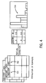
- Fig. 1 illustrates an embodiment of a management system 100 operable to manage maintenance on an imaging system 105 employing a radiation source 110.
- the embodiment of the radiation source 110 of the imaging system 105 can comprise x-ray tube assembly 115 (also referred to as "the tube assembly 115").
- the illustrated embodiment of the imaging system 105 is of a digital x-ray imaging system that includes a detector 120 operable to detect attenuation of a stream of radiation 122 transmitted from the tube 115.
- x-ray system 105 can vary.
- x-ray tubes such as conventional x-ray systems, CT systems, tissue ablation or cauterization system, sterilizing system, x-ray crystallography system to reveal a nature of a crystal lattice, x-ray microscopic analysis system to produce images of small objects, industrial radiography systems to inspect industrial parts or welds, airport security systems, etc.
- x-ray system 105 can vary.
- the embodiment of the radiation source 110 can receive power and control signals from a controller 125.
- the controller 125 can convert alternating current power to direct current power and can apply controlled pulses of DC power to the tube 115 to induce emissions of x-ray radiation for examination purposes.
- the controller 125 can monitor a range of operating conditions or parameters of the tube 115, as described in more detail below.
- a set of conductors 130 can convey power and control signals from the controller 125 to the tube 115.
- the tube 115 of the radiation source 110 produces the stream of radiation 122.
- the stream of radiation 122 can be directed through a collimator 140 and passes through a subject 145, such as a human patient.
- the detector 120 can measure and convert attenuation of the stream of radiation 122 through the subject 145 to image data.
- the detector 120 can convey the image data as signals to the controller 125 for processing.
- the controller 125 can provide control signals to regulating scanning of the detector 120. Moreover, the controller 125 may perform additional signal processing or signal filtering functions. The controller 125 can also acquire the image data and performs further processing and filtration functions. In particular, the controller 125 can derives discrete data from the acquired signals and reconstructs useful images from the data.
- the controller 125 can include a processor 150 generally configured to execute program instructions stored in the memory 155. Although the memory 155 and processor 150 are shown at the controller 125, it should be understood that the memory 155 or processor 150 can comprise remote portions.
- the controller 125 can also be in communication with an input device 160 and an output device 165.
- Examples of the input device 160 include a keyboard, an touch screen or graphic interface, mouse, toggle switches, etc.
- Example of the output device 165 can include monitors, touch-screens or graphic interfaces, kiosks, dashboards, etc.
- the input and output devices 160 and 165 can be combined as an operator interface in communication to exchange configuration data, examination requests, and so forth with the controller 125.
- the operator interface can include an operator workstation that permits clinicians or radiologists to request and control specific examinations, review data log files, view reconstructed images, and output reconstructed images on a tangible medium, such as photographic film.
- the controller 125 can store the image data in the memory 150.
- the memory 150 may also store configuration parameters, data log files, and so forth.
- the controller 125 can provide signals to control emission of x-ray radiation from the radiation source 110.
- the controller 125 may also include communication circuitry (wired or wireless) for providing interactive data exchange with remote computer stations, such as a remote service center as described more fully below.
- the system 100 may also include sensors 170 to detect specific operating parameters of the radiation source 110, such as (but not limited to) temperature, current, voltage, and vibration, values of which may also be stored and analyzed as described below.
- sensors 170 to detect specific operating parameters of the radiation source 110, such as (but not limited to) temperature, current, voltage, and vibration, values of which may also be stored and analyzed as described below.
- system 100 can include other control and interface circuitry on other scanner types, such as conventional x-ray systems, CT imaging systems, and so forth.
- system 100 can include the controller 125 to regulate emission of x-ray radiation for examination or calibration purposes.
- system 100 can include capabilities to monitor or track performance of the tube assembly 115 during such examination or calibration sequences such that parameters considered as leading indicators of tube failure may be acquired, stored and analyzed.
- Fig. 2 illustrates an embodiment of the radiation source 110, including the x-ray tube assembly 115.
- the embodiment of the x-ray tube assembly 115 can include an anode assembly 180 and a cathode assembly 185.
- the anode and cathode assemblies 180 and 185 can be positioned within a casing 190 which may be made of aluminum and lined with lead material composition.
- the tube assembly 115 can be supported from the anode and cathode assemblies 180 and 185.
- the tube assembly 115 can further include an envelope 195, with a rotor 200 positioned therein generally adjacent to the anode assembly 185.
- a stator 205 can at least partially surround the rotor 200.
- the casing 190 can be filled with a cooling medium 215 such as oil around the envelope 195.
- the cooling medium 215 can also enhance high voltage insulation.
- the anode assembly 180 can be positioned within the envelope 195.
- An embodiment of the anode assembly 180 includes an anode 220 having a front portion comprising a target disc 225.
- the target disc 225 can include a target or focal surface 230.
- the cathode assembly 185 can include a cathode 235 coupled to a series of electrical leads 240.
- the cathode 235 can include a central shell 245 from which a mask 250 extends.
- the mask 250 can enclose and conduct the leads 240 to a cathode cup 255.
- the cathode cup 255 can serve as an electrostatic lens that focuses electrons emitted from a heated filament (not shown) supported by the cup 255.
- Control signals conveyed from the controller 125 via the leads 240 to the cathode 235 can regulate or control energizing of the cathode filaments (not shown) within the cup 240 so as to produce an electron beam 260.
- the beam 260 can be directed to strike the focal surface 230 of the anode target disc 225 so as to cause or generate the stream of radiation 122 therefrom to be transmitted from the x-ray tube assembly 115.
- a deflection coil 270 can produce a magnetic field to control the direction and orientation of the stream of radiation 122.
- the controller 125 can control the intensity and direction of magnetic field produced by the deflection coil 270.
- the stream of radiation 122 can exit the radiation source 110 through an aperture 275 in the casing 190 provided for this purpose.
- Stream of x-ray radiation 122 can be produced in the x-ray tube assembly 115 when, in a vacuum, electrons are released and accelerated by the application of high voltages and currents to the cathode assembly 185 and then abruptly intercepted by the anode target disc 225.
- the voltage difference between the cathode 235 and anode 220 may range from tens of thousands of volts to in excess of hundreds of thousands of volts.
- the anode target disc 225 may be rotated such that electron beams are constantly striking a different point on the target or focal surface 230.
- the desired radiation may be emitted by substances such as radium or artificial radiotropics, as well as electrons, neutrons and other high speed particles.
- radium or artificial radiotropics as well as electrons, neutrons and other high speed particles.
- a vacuum on the order of 10.sup.-5 to about 10.sup.-9 torr at room temperature can be maintained to permit transmission of the electron beam 260 between the anode 220 and cathode 235.
- the controller 125 can track or acquire feedback or operating parameters of the radiation source 110 or tube assembly 115. Certain of these parameters to be described later can be considered as predictive of future failure or survivability of the radiation source 110 or tube assembly 115. Such parameters may be measured via the sensors 170 (see Fig. 1 ), and can also be available from the characteristics of the control and power signals applied to the radiation source or tube assembly 115.
- While the electron beam 260 is created in a vacuum, particulates or contaminants may be present in the tube assembly 115. Such particulates may be introduced in the tube assembly 115 via leaks, degradation of components, decomposition of components, and so forth. When the electron beam 260 impacts such particulate matter, the electron beam 260 may continue toward the anode target disk 225 or the electron beam 260 may be deflected from the target disk 225.
- anomalies e.g., current anomalies
- An example of such anomaly is an anode high current discharge, also referred to as an anode overcurrent event, associated with the particulate encountering the electron beam and the beam continuing along its path to impact the anode target disk 225.
- An example of such anomaly is a "spit" event, associated where the particulate may divert the electron beam from the anode target disk 225 to cause the current discharge event.
- the controller 125 can receive feedback of measurement of current at the anode target disk 225 and via comparators and other circuitry or software modules can detect or track occurrence of the anomalies, as well as distinguish between anode overcurrent events and spits. The controller 125 can record and save detection of occurrence of such anomaly events at the memory 155.
- the controller 125 can also be configured to acquired data from one or more sensors 170 or feedback from components of the x-ray tube assembly 115, radiation source 110 or imaging system 105 to track other failure modes for tube assemblies, including rotor failure and filament failure.
- the anode of the tube assembly 115 can continuously rotate to provide fresh material under the electron beam 122 by vacuum compatible bearings.
- the rotor control function can provide three phase motor power to the rotating anode of the tube assembly 115.
- the high stress environment of heat and mechanical load can increase likelihood of an anode rotor bearing failure.
- the controller 125 can acquire data (e.g., from the rotor control) of increased amount of current from the motor control during acceleration and run states relative to thresholds, which can be determinative of an increased likelihood or lower survivability due to a failure condition of the anode rotor bearing.
- This above-described acquired data of failure condition of the anode rotor bearing can be logged at the memory 155.
- filament failure can another significant failure mode.
- the tungsten alloy filament can be electrically heated in the cathode structure to very high temperatures to create an electron cloud. Open filament circuit is one of the common failure modes.
- the mA Filament Control Board monitors the voltage at the output of the filament inverter. The controller can detect or receive data of an improper voltage via the filament control board, and log the anomaly at the memory 155.
- the controller 125 can track measurement of additional parameters. For example, the controller 125 can detect and record a number of spits per day of operation. Moreover, the controller 125 can detect interruption of current to the tube assembly 115 upon the occurrence of the spit event, and the subsequently reapplication of current during an examination sequence. Such events can recorded by the controller 125 and logged in the memory 150 for each day of operation. The controller 125 can receive instructions or be preset to detect a maximum "spit rate" limit (e.g., in terms of spits per unit time).
- the controller 125 can automatically abort or otherwise stop a scan or examination. For example, in one embodiment, if the controller 125 detects measures the spit rate to be over 32 spits/second, the controller 125 can automatically abort or otherwise cause a present examination scan to be aborted. Such events can be termed "spit rate exceeded" errors (SREs).
- SREs spit rate exceeded errors
- the controller 125 can also track a number of SREs per day and store in the memory 150.
- the controller 125 also records events when rotor drive control circuit detects an anomaly, for example, if the rotor cannot be brought up to speed in a prescribed time, or an overcurrent in acceleration, etc.
- the controller 125 also monitors the filament voltage and current and records events when these parameters are out of bound indicating a possible open filament.
- a first baseline model or algorithm comprising parameters that are dependent or associated with occurrence of event codes can be integrated with a second model or algorithm comprising tracked parameters associated with usage of the radiation source 110 or tube assembly 115 to create a composite algorithm to predict a likelihood or failure of the tube assembly 115.
- the rate of occurrence of anode overcurrent events and SREs, as well as rotor and filament events can be applied to this composite algorithm to predict the likelihood of failure or survivability of the tube assembly 115.
- An example of creating the composite algorithm can be according to a technique as described below.
- Fig. 3 includes a flow diagram to illustrate an embodiment of a method 300 of operation of the system 100 in managing a maintenance of the radiation source 110. It should be understood that the sequence of the acts or steps of the method 300 as discussed in the foregoing description can vary. Also, it should be understood that the method 300 may not require each act or step in the foregoing description, or may include additional acts or steps not disclosed herein. It should also be understood that one or more of the steps of the method 300 can be represented as computer-readable program instructions in the memory 150 for execution by one or more processors of the controller 125 or remote computer. This method 300 can be modified or customized for each individual tube assembly 115 based on tracking of specific events and parametric or usage measurements.
- One embodiment of the method 300 generally includes a step 305 of calculating or outputting an initial or baseline probability of failure or survivability, independent of machine condition or usage, such as by applying a reliability model.
- the step 305 can include acquiring input data and/or reliability models from one or more of a predetermined manufacturer's/engineering age-based reliability model, or on a reliability model created from acquired date across a population of machines.
- step 305 can include creating an algorithm or baseline model of a likelihood of or to predict a time to failure of the tube assembly 115. Based on a representative training sample dataset with known incidences of failure, step 305 can include identifying parameters of age and/or machine data and/or usage profile to be weighted as part the baseline reliability model.
- One embodiment of the baseline reliability model can include mathematical function that provides a probability of survival of a component given the age of the component.
- the baseline reliability model given the age of the component can include a weibull model whose parameters are estimated based on testing in design (e.g., HAST (Highly Accelerated Stress Test) or by observing population of the component in field.
- the baseline reliability model could also be a non-parametric model based on sample data from the observed population in field.
- baseline reliability model can be independent of usage of the tube assembly, radiation source, or system.
- Another embodiment of the baseline reliability model can be weighted by parameterized usage profile in a non-parametric reliability model framework such as Cox PH model wherein the hazard at time (t) can a function of baseline hazard using age (h 0 (t)) which can be accelerated by the variables (X).
- the coefficients ⁇ can be weights assigned to different independent usage variables (X).
- An embodiment of the step 305 can include creating baseline reliability model to calculate the probability of survival of one or more components of the system 100 based on acquired data of an existing population of tube assemblies 115, such as represented by a Weibull distribution algorithm with defined parameters for shape and scale.
- Another embodiment of the step 305 of creating the baseline reliability model can be correlated to reliability test data acquired from the manufacturer.
- the baseline reliability model can be supplemented with weighted parameters for batch period information acquired to incorporate or represent variation in manufacturing.
- a variable for the manufacturing model/batch period information can be incorporated into the baseline reliability model.
- the batch variable can be incorporated as a categorical variable similar to variable (X) in the Cox-PH model described above.
- the batch variable can also be incorporated in the form of a stratified model; where each model period can have its own baseline reliability model with common values for the coefficients ⁇ assigned to usage.
- Step 310 can include acquiring and applying measurements of additional parameters for application in one or more of the above-described models or algorithms (e.g., system usage model, component usage model, composite usage model) in step 305.
- the measured parameters can include machine data for one or more components or subsystems, and usage at the radiological imaging level or component level of the radiation source 110 or tube assembly 115.
- one embodiment of the measurement of parameters for application in the model can include continuous measurements directed to failure at the sub-system/component level (e.g., directed to failure prognostics of the tube assembly 115, data directed to the tube rotor 200, measurements of high voltage related failures, etc.).
- the parameters represented in one or more of the above-described usage or composite models can represent measurement data of occurrence of discrete events, also referred to as event codes.
- the occurrence of event codes can include the occurrence of exceptions/error messages logged in the imaging system 100. Measuring these event codes can include acquiring feedback and detecting crossing of trend in data relative to pre-set threshold levels, occurrence or output of system state messages (e.g., abort of exam etc.) due to interaction with type of imaging scans performed, conditions of operation of the radiological imaging system or radiation source 110.
- the occurrence of these event codes may be discontinuous and noisy in nature.
- Step 310 can further include measuring or acquiring data of usage of the imaging system or radiation source 110 measured across different dimensions based on nature of the measurement and its relationship to the component.
- the usage measurements can be broadly classified into the following categories: system usage parameters can include quantity and type of usage for the imaging system in general (e.g., number of scans/diagnostic images acquired over a period of time, a type of diagnostic exams performed (degree of mix of types of diagnostic exams performed by a given system, etc.).
- usage parameter measurements can also include tracking or acquiring measurement of component usage-parameters which can be incremented based on some measure of usage specific to the component (e.g., milli-amp seconds (mAS) as referred to by reference 312 relative to a time stamp 314) of usage or operation of tube assembly 115 over life of tube assembly 115), and creating a model or algorithm (e.g., based on histogram and reference 316) representative the rate of mAS usage independent of time (e.g., mAS usage per tube assembly 115).
- mAS milli-amp seconds
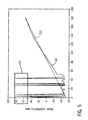
- Step 320 can include applying a filter (also referred to as a "bad data filter”) to remove outlying measurement data (relative to a threshold). Includes creating or developing a model or algorithm that defines or represents a baseline or continually measured/modified trend of usage f a feature (e.g., MaS records a measure of usage per tube).
- a filter also referred to as a "bad data filter”
- Step 320 in applying the filter can include calculating or acquiring a rate of usage (e.g., example of mAS usage illustrated as reference 321), comparing the acquired measured rate 321 relative to the trend model or algorithm 322, and calculating a departure from the trend model 322.
- a bad data filter can be operable to remove data categorized as large-scale single outliers (examples generally shown within frame and reference 323 of Fig. 5 ), which can be physically infeasible and therefore represent bad data.
- the bad data filter can remove or eliminate these large-scale single outliers 323, based on developed feature for new real-time data in production to improve robustness of system 100.
- Step 325 can include extracting details of one or more features to improve dimension reduction and to extract relevant input data.
- An embodiment of the step 310 of measuring usage can cause or trigger the step 325 of extracting features, such as those independent of the age of the component and usage parameters.
- One embodiment of step 325 can include applying or executing feature extractions tools to both continuous and discrete (event) data.
- Feature extraction for parametric data can includes dimension reduction strategies (multivariate feature extraction: PCA; or time series feature extraction FFT; wavelet etc.).
- the discrete events (event codes) can be representative of a change in system states or certain measurements crossing predetermined threshold values. Typically a large number of such events are reported by the system ( ⁇ 2000 unique event).
- Event extraction consists of selecting events related to failure modes of interest and the coefficient associated with each event in Eq. (1). This can be done in step 325 by acquiring or tracking a frequency of occurrence of each event code in a given time window as a feature corresponding to the event, based on an impact occurrence of an event code can decrease with time. Occurrences of the event code relative to a time window (e.g., 20 days) or individual occurrences can be weighted based on time of occurrence of the event code.
- a time window e.g. 20 days
- An embodiment of step 330 can include combining or integrating one or of the above-described usage algorithms with another (system or one or more component level algorithms) to create a composite or combined model or algorithm to calculate the survival probability of the system 100.
- the step 330 can include acquiring measurements of both system level usage and component usage parameters to calculate or output a combined usage parameter value for integration in the usage algorithm.
- the usage parameters at the system level or component level may not be completely independent of each other.
- the step 330 can include calculating a composite usage of the system 100 that represents a weighted combination of one or more system level usage parameters (e.g., exam counts) with one or more of the component level usage-parameters (e.g., MAS/per component).
- step 330 can include integrating or combining algorithms dependent on acquired usage as described above with one or more algorithms dependent on acquired data of event codes.
- Step 330 can include identifying multiple error codes as significant based on the analysis that can be applied in combination with measurement of the usage rate to the failure prediction model.
- step 330 can include calculating significance of event codes in correlation or proportion to tracking of the number of occurrences (e.g., four different event codes and reference 331) at a sub-component of the rotor 200 in combination with the severity of occurrence (e.g., failure as shown by reference 332) of the sub-component of the rotor 200.
- the severity can be assigned predetermined weights or values and stored at the controller 125.
- Step 330 can include assigning or calculating a weight to each measurement of component usage or parameters for error code features relative to one another.
- the method 300 can include calculating a composite parameter generally equal to a weighted coefficient multiplied to the measurement of each individual error code parameter.
- the controller 125 can select or receive instructions to use the set of error codes related to the specific failure modes that are detected based on the ability of the measurement of the parameters of the error code features to differentiate between the system 100 with a failing tube (a tube with little remaining life) versus the system with a normal tube a tube with significant remaining life).
- step 330 can include combining one or more aspects or portions of the algorithms described above with another and is not limiting on the technique described herein.
- Step 335 includes applying a conditioner function.
- the step 335 can include applying a conditioner function to adjust the reliability model so as to calculate a per-system calculation of survival probability.
- the conditioner function can be defined as a Bayesian type filter operable to modify the prior probability of failure given new information regarding system condition.
- a typical embodiment of the conditioner function is the exponential function.
- An embodiment of step 335 can include acquiring a representative dataset sample (e.g. training) of component failures, creating a model or algorithm of the conditioner function after accounting for the reliability output according to the reliability algorithm.
- the conditioner function can comprise a selection of optimum set of features (from a series of tracked features) to be included in or applied to the reliability model based on the corresponding significance of weighted coefficients.
- An example of the model can calculate a reliability or probability of failure or survival of a tube assembly 115 based on training or calibration data for the system of interest for a condition of at least one of normal and failed radiation source 110 or tube assembly 115.
- Step 340 includes integrating or combining the non-usage baseline reliability model with the reliability model based on usage data, parametric and feature extraction (e.g., error codes) to predict the survival or limited life remaining of the tube assembly 115.
- the individual coefficients ( ⁇ ) applied to one or more of the non-usage baseline reliability models/algorithms or parameters described above can be estimated based on sample population.
- the relationship between the non-usage baseline reliability model or parameters described above can be captured by interaction terms.
- One or more parameters can be weighted by their respective coefficients, which are obtained from training historical data, are summed to form a combined feature, which is then input into the conditioner 445 (see Fig. 8 ) and further transformed into a number representing the risk of failure due to the exhibited operating feature of the tube assembly 115.
- the integrated/combined model can be a weighted combination of the non-usage model in combination with the non-usage model.
- Fig. 7 shows an illustration of an example of calculation of probability of survival based on non-usage reliability model (e.g., age only) (see reference 342) that can be adjusted (see reference 344) to show a change in predicted reliability or failure or survivability dependent or changed in response to acquired measurements of error code (see reference 346) and usage parameters, combined with weighted coefficients as described above.
- non-usage reliability model e.g., age only
- usage parameters e.g., weighted coefficients as described above.
- Fig. 8 illustrates an embodiment of a software or software package 400 that comprises a series of program modules of instructions that can be stored in the memory 155 for execution by the processor 150 of the controller 125.
- the embodiment of the series of program instructions of the software 400 generally correlate with the method 300 described above to manage and output the survivability of the imaging system 105.
- Module 405 generally includes program instructions to acquire data of non-usage parameters associated with the imaging system 105, either from the imaging system 105 or via the input160.
- Module 410 generally includes program instructions to acquire a baseline reliability algorithm(s) and data from at least one of the manufacturer of the imaging system 105 or radiation source 110 thereof, or to acquire a dataset or algorithm from a compilation acquired from a population of other imaging systems independent of the imaging system 105 or radiation source 110 of interest.
- Module 415 generally includes program instructions directed to applying the acquired output from at least one or both of the modules 405 and 410 in calculating or creating an output of the baseline probability of the failure or survivability of the system 105 or the radiation source 110
- Module 420 generally includes program instructions to acquire measurements of logs or occurrences of event codes, usage data, or other parameter metrics associated with operation of the imaging system 105 or the radiation 110 or tube assembly 115 thereof.
- Module 425 generally includes program instructions to filter bad data before application in the algorithm to predict failure or survivability of the imaging system 105 or radiation source 110 or tube assembly 115 thereof, similar to step 320.
- Module 430 generally includes program instructions to extract or transform features from the output acquired from the module 425.
- An example of module 430 in extracting the feature can include instructions to calculate or measure the frequency of occurrence of each event code in a given or acquired time window which may correspond to an event, or measure a change of an impact of an occurrence of an event code with time, etc.
- Module 435 generally includes program instructions to calculate or adjust weighted coefficients to be applied to the above-described parameters comprising the algorithm 440 in calculating the failure or survivability of the imaging system 105 or radiation source 110 or tube assembly 115 thereof.
- Module 445 generally includes program instructions to apply a conditioner function as described in step 335.
- Module 450 includes instructions to combine or integrate the output of the baseline reliability or probability algorithm with operating parameter algorithms/models so as calculate probability of time period to failure or survivability of the system 105 or radiation source 110 or tube assembly 115 thereof, as described in step 340.
- the controller can calculate the baseline probability of survival of the component for any time (t 0 ⁇ t ⁇ t 1 ); where (t 1 - to) is the acquired or preset prediction horizon or prediction interval forward from the present.
- the module 445 of the conditioning function can modify or adjust acquired data or output of the usage based reliability model based on the usage and data acquired of the error code features extracted until time to, and the estimated usage feature values until t 1 .
- a pre-set threshold can be determined for survival probability for which a trigger can be generated to inform the service operations to service/replace the component, e.g., a survival probability of 0.05 can be considered as the threshold to replace/service the tube.
- the estimated time to failure from the accelerated reliability model can be used in conjunction with the time required to service the component to generate the trigger, e.g., if the time to failure is estimated to be 3 days and the time to repair the component is 2 days a trigger may be generated to allow sufficient time to service the component without causing downtime.
- the above provides a description of embodiment of the system 100 and method 300 to predict a failure of an imaging system 105 that includes an x-ray tube assembly 115 as a radiation source 110.
- the embodiment of the method 300 can comprise the steps of acquiring an age of the x-ray tube assembly 115; calculating a baseline probability of a survivability of the tube assembly 115 for a remaining time period independent of a usage of the tube assembly 115; acquiring measurement of at least one operating parameter of the x-ray tube assembly 115; and automatically changing the probability of a survivability of the x-ray tube assembly 115 in response to the measurement of the at least one operating parameter of the x-ray tube assembly 115.
- An embodiment of the at least one operating parameter can include a measure of a severity of an occurrence of an event code generated by the imaging system 105, the event code associated with an abnormal operating condition of the radiation source 110.
- An embodiment of measurement of the at least one operating parameter can include measurement of a frequency of an occurrence of an event code generated by the imaging system 105, or the event code associated with an abnormal operating condition of the radiation source 110.
- the method 300 can further include the step of extracting the event code from acquired data received from the imaging system 105, the event code representative of at least one of: an error message, a measurement outside of a threshold range, and a message indicative of a state of the imaging system 105.
- An embodiment of the baseline probability of the survivability of the system 105 can be dependent on acquired data of a survivability for a population of other x-ray tube assemblies 115 with age and usage of the imaging system 105.
- An embodiment of the at least one operating parameter can generally equal a measure of usage of imaging system 105 weighted relative to a measure of an occurrence of event codes associated with operation of the imaging system 105, or the at least one operating parameter can generally equal a measure of usage of the imaging system 105 weighted relative to a measure of usage of the tube assembly 115 of the system 105 independently thereof.
- An embodiment of the step of automatically changing the baseline probability of time to failure of the imaging system 105 can include decreasing the probability survivability of the imaging system 105 in response to acquiring a measurement of an occurrence of an event code outside a threshold range, or can include decreasing the probability survivability in proportion to a predicted value of usage of one or more of the imaging system 105, the radiation source 110, and the tube assembly 115.
- the system 100 can comprise a storage medium having a plurality of programmable storage instructions; and a processor in communication with the imaging system, the plurality of program instructions to instruct the processor to perform the steps of: acquiring an age of the x-ray tube assembly 115, calculating a baseline probability of a survivability of the tube assembly for a remaining time period dependent on the age of the tube assembly, acquiring measurement of at least one operating parameter of the x-ray tube assembly, and automatically changing the baseline probability of a survivability of the imaging system for the remaining time period in response to the measurement of the at least one operating parameter of the x-ray tube assembly.
- the at least one operating parameter includes a measure of a severity of an occurrence of an event code generated by the imaging system, the event code associated with an abnormal operating condition of the radiation source, or a measure of usage of the x-ray tube assembly.
- measurement of the at least one operating parameter includes measurement of a frequency of an occurrence of an event code generated by the imaging system, the event code associated with an abnormal operating condition of the radiation source.
- the system of claim 10 further comprising the step of extracting the event code from acquired data received from the imaging system, the event code representative of at least one of: an error message, a measurement outside of a threshold range, and a message indicative of a state of the system.
- the baseline probability of the survivability of the system is dependent on acquired data of a survivability for a population of other x-ray tube assemblies with age and usage of the imaging system.
- the at least one operating parameter generally equals a measure of usage of imaging system weighted relative to a measure of an occurrence of event codes associated with operation of the imaging system.
- the at least one operating parameter generally equals a measure of usage of the imaging system weighted relative to a measure of usage of the tube assembly of the system independently thereof.
- the step of automatically changing the baseline probability of time to failure of the imaging system includes decreasing the probability survivability of the imaging system in response to acquiring a measurement of an occurrence of an event code outside a threshold range.
- the step of automatically changing the baseline probability of time to failure of the imaging system includes decreasing the probability survivability in proportion to a predicted value of usage of one or more of the imaging system, the radiation source, and the tube assembly.
- the baseline probability of a survivability of the imaging system for the remaining time period includes a predicted number of hours or days to failure.
- a technical effect of the above-described system 100 and method 300 includes combining machine data with reliability model and usage profile to provide higher accuracy for the failure prediction, as well as high accuracy prediction of minimum remaining life so as to reduce cost of proactive replacement.
- the accuracy of the prediction to failure can depend on the time frame or horizon for the failure prediction, and the nature of prediction (prediction of failure of individual components versus prediction of failure of the system 105 or components of fleet of systems).
- a first example is directed to failure prediction of a component that is system specific and having a short-term prediction horizon or time frame, and based on measured or acquired data of machine event codes and usage.
- the system 100 and method 300 can combine the reliability model with machine event codes and usage data for a specific system.
- the system 100 can predict the probability of survival for the component in the required time window (e.g., 30 days) based on the modeled usage profile for the imaging system 105.
- the system 100 and method 300 can be automatically updated based on new data sent by the system to update parametric/error and usage features, and can acquire updated values to provide a new estimate of time to failure and the confidence intervals for the same.
- the system 100 and method 300 can also integrate the failure prediction with business and logistics inputs in terms of transportation time (based on distance of the hospital to depot), cost of downtime to the hospital, the model can be used to determine optimum trigger for service of component. These inputs can be used as additions to the constraints outlined above in terms of accuracy and TTF requirements in the model for optimum prediction.
- the system 100 and method 300 can also be used to predict the number of failures of tubes for a given time period in a given geographical area.
- the outputs of the system 100 and method 300 can enhance predictions of survival of components and/or system 105 by combining output from the reliability model with acquired data of usage patterns for individual systems 105 or assemblies 115.
- the system 100 and method 300 can be scaled to the required prediction horizon or time frame (e.g. 4 months) and for a group of components or systems 105.
- the length of prediction horizon and grouping of systems 105 can be determined based on geographical zones and horizon for inventory planning.
- the proposed system 100 can then use the probability of failures for each individual system 105 (based on its age and usage characteristics) to provide a stochastic estimate of expected number of tube failures in the geographical area for given time frame. This would provide a more accurate estimation than deterministic estimation of failures of tube assemblies 115 based on age alone.
- Another technical effect of the above-described system 100 and method 300 includes providing robust failure prediction and sufficient time to failure to prevent downtime by proactive service. Further the prediction is based on the modeling the usage profile that allows for leaving minimum remaining life at prediction, since it conditions the time to failure based on predicted usage of the component.
- the ability to perform failure prediction, e.g., for tube assemblies 115 for example in CT imaging systems 105 can provide significant benefit to customer in terms of reduced downtime and the focus of the proposed methodology can be able to predict (e.g., at least 2 days) before failure. Further, the ability to predict tube failure allows for savings per tube requiring special handling. Also, the system 100 and method 300 can calculate a minimum remaining life on the tube assembly 115 as the cost of each day of remaining life on a tube assembly 115.
- Another technical effect of the system 100 and method 300 given the large scale of the install base and the number of expected failures of x-ray tube assemblies 115 per year, provides for accurate prediction of failures of tube assemblies 115 based on geographical area. This can help both ensuring availability of tube assemblies 115 in the closest depot for the imaging system 105 having a failure of the tube assembly 115 and also help in reducing inventory holding cost.
Abstract
Description
- The subject herein generally relates to a system and method to perform maintenance on a radiological imaging system, and more specifically, system and method to predict failure of an X-ray tube of the radiological imaging system.
- A leading cause of unplanned shutdown of radiological imaging systems (e.g., X-ray, Computed Tomography (CT)) includes failure of an X-ray tube installed therein. Tube failure can be highly disruptive to the delivery of healthcare to patients, as well as the operation and revenue generation of the radiological imaging systems.
- The above-mentioned problem can be addressed by the subject matter described herein in the following description.
- The system and method of the subject matter described herein provide enhanced prediction of a survivability for a remaining time period of an imaging system having a radiation source with an x-ray tube assembly. The system and method can increase the lead time for service operations to schedule shipment and installation of the replacement tube with reduced unplanned downtime.
- According to one embodiment, a method to predict a failure of an imaging system that includes a x-ray tube assembly as a radiation source is provided. The method includes the steps of acquiring an age of the x-ray tube assembly; calculating a baseline probability of a survivability of the tube assembly for a remaining time period independent of a usage of the tube assembly; acquiring measurement of at least one operating parameter of the x-ray tube assembly; and automatically changing the probability of a survivability of the x-ray tube assembly in response to the measurement of the at least one operating parameter of the x-ray tube assembly.
- According to another embodiment, a system to predict a failure of an imaging system that includes a radiation source having an x-ray tube assembly is provided. The system comprises a storage medium having a plurality of programmable storage instructions; and a processor in communication with the imaging system, the plurality of program instructions to instruct the processor to perform the steps of: acquiring an age of the x-ray tube assembly; calculating a baseline probability of a survivability of the tube assembly for a remaining time period dependent on the age of the tube assembly; acquiring measurement of at least one operating parameter of the x-ray tube assembly; and automatically changing the baseline probability of a survivability of the imaging system for the remaining time period in response to the measurement of the at least one operating parameter of the x-ray tube assembly.
- Various other features, objects, and advantages of the invention will be made apparent to those skilled in the art from the accompanying drawings, and detailed description thereof, in which:
-
Fig. 1 includes a diagrammatical representation of an imaging system in combination with an embodiment of a management system of the subject matter described herein, the imaging system incorporating an x-ray tube as a source of radiation. -
Fig. 2 includes a detailed diagram of an embodiment of an x-ray tube of the type incorporated in the imaging system ofFig. 1 . -
Fig. 3 includes a flow diagram illustrative of an embodiment of a method managing maintenance of the imaging system inFig. 1 . -
Fig. 4 includes a graphical representation of an embodiment of extraction of an occurrence of a feature or event code and creating a model of trend thereof in occurrence dependent on a histogram. -
Fig. 5 includes a graphical illustration of a filter to acquired system or component level usage data, the filter generally operative to remove outlying data relative to a historical trend. -
Fig. 6 includes a graphical illustration of a step of identifying significance of multiple error codes that can be applied in weighted relevance in combination with measurement of the usage parameters to calculate the probability of survivability of the system, radiation source, or tube assembly. -
Fig. 7 includes a graphical illustration of an embodiment of the step of adjusting a baseline probability of survivability of the imaging system or tube assembly thereof dependent on acquired data of occurrence of event codes with respect thereto. -
Fig. 8 illustrates a block diagram illustrative an embodiment of a software comprising a series of modules of program instructions operable to instruct a processor of the management system to perform the steps of managing the imaging system in accordance with the embodiment of the method ofFig. 3 . - In the following detailed description, reference is made to the accompanying drawings that form a part hereof, and in which is shown by way of illustration specific embodiments that may be practiced. These embodiments are described in sufficient detail to enable those skilled in the art to practice the embodiments, and it is to be understood that other embodiments may be utilized and that logical, mechanical, electrical and other changes may be made without departing from the scope of the embodiments. The following detailed description is, therefore, not to be taken as limiting the scope of the invention.
-
Fig. 1 illustrates an embodiment of amanagement system 100 operable to manage maintenance on animaging system 105 employing aradiation source 110. The embodiment of theradiation source 110 of theimaging system 105 can comprise x-ray tube assembly 115 (also referred to as "thetube assembly 115"). The illustrated embodiment of theimaging system 105 is of a digital x-ray imaging system that includes adetector 120 operable to detect attenuation of a stream ofradiation 122 transmitted from thetube 115. Yet, the type (e.g., systems employing x-ray tubes such as conventional x-ray systems, CT systems, tissue ablation or cauterization system, sterilizing system, x-ray crystallography system to reveal a nature of a crystal lattice, x-ray microscopic analysis system to produce images of small objects, industrial radiography systems to inspect industrial parts or welds, airport security systems, etc.) ofx-ray system 105 can vary. - The embodiment of the
radiation source 110 can receive power and control signals from acontroller 125. Thecontroller 125 can convert alternating current power to direct current power and can apply controlled pulses of DC power to thetube 115 to induce emissions of x-ray radiation for examination purposes. Moreover, thecontroller 125 can monitor a range of operating conditions or parameters of thetube 115, as described in more detail below. A set ofconductors 130 can convey power and control signals from thecontroller 125 to thetube 115. - Under the command of the
controller 125, thetube 115 of theradiation source 110 produces the stream ofradiation 122. The stream ofradiation 122 can be directed through acollimator 140 and passes through asubject 145, such as a human patient. Thedetector 120 can measure and convert attenuation of the stream ofradiation 122 through thesubject 145 to image data. Thedetector 120 can convey the image data as signals to thecontroller 125 for processing. - The
controller 125 can provide control signals to regulating scanning of thedetector 120. Moreover, thecontroller 125 may perform additional signal processing or signal filtering functions. Thecontroller 125 can also acquire the image data and performs further processing and filtration functions. In particular, thecontroller 125 can derives discrete data from the acquired signals and reconstructs useful images from the data. - The
controller 125 can include aprocessor 150 generally configured to execute program instructions stored in thememory 155. Although thememory 155 andprocessor 150 are shown at thecontroller 125, it should be understood that thememory 155 orprocessor 150 can comprise remote portions. - The
controller 125 can also be in communication with aninput device 160 and anoutput device 165. Examples of theinput device 160 include a keyboard, an touch screen or graphic interface, mouse, toggle switches, etc. Example of theoutput device 165 can include monitors, touch-screens or graphic interfaces, kiosks, dashboards, etc. The input andoutput devices controller 125. The operator interface can include an operator workstation that permits clinicians or radiologists to request and control specific examinations, review data log files, view reconstructed images, and output reconstructed images on a tangible medium, such as photographic film. - The
controller 125 can store the image data in thememory 150. Thememory 150 may also store configuration parameters, data log files, and so forth. Thecontroller 125 can provide signals to control emission of x-ray radiation from theradiation source 110. Thecontroller 125 may also include communication circuitry (wired or wireless) for providing interactive data exchange with remote computer stations, such as a remote service center as described more fully below. - The
system 100 may also includesensors 170 to detect specific operating parameters of theradiation source 110, such as (but not limited to) temperature, current, voltage, and vibration, values of which may also be stored and analyzed as described below. - As noted above, the foregoing description of the
system 100 is directed to digital x-ray imaging. Of course, thesystem 100 can include other control and interface circuitry on other scanner types, such as conventional x-ray systems, CT imaging systems, and so forth. In general, however,such system 100 can include thecontroller 125 to regulate emission of x-ray radiation for examination or calibration purposes. Moreover, for implementation of the technique described herein,such system 100 can include capabilities to monitor or track performance of thetube assembly 115 during such examination or calibration sequences such that parameters considered as leading indicators of tube failure may be acquired, stored and analyzed. -
Fig. 2 illustrates an embodiment of theradiation source 110, including thex-ray tube assembly 115. The embodiment of thex-ray tube assembly 115 can include ananode assembly 180 and acathode assembly 185. The anode and cathode assemblies 180 and 185 can be positioned within acasing 190 which may be made of aluminum and lined with lead material composition. Thetube assembly 115 can be supported from the anode andcathode assemblies tube assembly 115 can further include anenvelope 195, with arotor 200 positioned therein generally adjacent to theanode assembly 185. Astator 205 can at least partially surround therotor 200. Thecasing 190 can be filled with acooling medium 215 such as oil around theenvelope 195. Thecooling medium 215 can also enhance high voltage insulation. - The
anode assembly 180 can be positioned within theenvelope 195. An embodiment of theanode assembly 180 includes ananode 220 having a front portion comprising atarget disc 225. Thetarget disc 225 can include a target orfocal surface 230. Thecathode assembly 185 can include acathode 235 coupled to a series of electrical leads 240. Thecathode 235 can include acentral shell 245 from which amask 250 extends. Themask 250 can enclose and conduct theleads 240 to acathode cup 255. Thecathode cup 255 can serve as an electrostatic lens that focuses electrons emitted from a heated filament (not shown) supported by thecup 255. - Control signals conveyed from the
controller 125 via theleads 240 to thecathode 235 can regulate or control energizing of the cathode filaments (not shown) within thecup 240 so as to produce anelectron beam 260. Thebeam 260 can be directed to strike thefocal surface 230 of theanode target disc 225 so as to cause or generate the stream ofradiation 122 therefrom to be transmitted from thex-ray tube assembly 115. Adeflection coil 270 can produce a magnetic field to control the direction and orientation of the stream ofradiation 122. Thecontroller 125 can control the intensity and direction of magnetic field produced by thedeflection coil 270. The stream ofradiation 122 can exit theradiation source 110 through anaperture 275 in thecasing 190 provided for this purpose. - Stream of
x-ray radiation 122 can be produced in thex-ray tube assembly 115 when, in a vacuum, electrons are released and accelerated by the application of high voltages and currents to thecathode assembly 185 and then abruptly intercepted by theanode target disc 225. The voltage difference between thecathode 235 andanode 220 may range from tens of thousands of volts to in excess of hundreds of thousands of volts. Moreover, theanode target disc 225 may be rotated such that electron beams are constantly striking a different point on the target orfocal surface 230. Depending upon the construction of thetube assembly 115, the desired radiation may be emitted by substances such as radium or artificial radiotropics, as well as electrons, neutrons and other high speed particles. Within theenvelope 195 oftube assembly 115, a vacuum on the order of 10.sup.-5 to about 10.sup.-9 torr at room temperature can be maintained to permit transmission of theelectron beam 260 between theanode 220 andcathode 235. - As noted above, in addition to providing power and control signals for operation of the
radiation source 110 ortube assembly 115, thecontroller 125 can track or acquire feedback or operating parameters of theradiation source 110 ortube assembly 115. Certain of these parameters to be described later can be considered as predictive of future failure or survivability of theradiation source 110 ortube assembly 115. Such parameters may be measured via the sensors 170 (seeFig. 1 ), and can also be available from the characteristics of the control and power signals applied to the radiation source ortube assembly 115. - While the
electron beam 260 is created in a vacuum, particulates or contaminants may be present in thetube assembly 115. Such particulates may be introduced in thetube assembly 115 via leaks, degradation of components, decomposition of components, and so forth. When theelectron beam 260 impacts such particulate matter, theelectron beam 260 may continue toward theanode target disk 225 or theelectron beam 260 may be deflected from thetarget disk 225. Each above-described incident of the particulate with the electron beam can create anomalies (e.g., current anomalies) in the signals exchanged between thetube assembly 115 and thecontroller 125. An example of such anomaly is an anode high current discharge, also referred to as an anode overcurrent event, associated with the particulate encountering the electron beam and the beam continuing along its path to impact theanode target disk 225. Another example of such anomaly is a "spit" event, associated where the particulate may divert the electron beam from theanode target disk 225 to cause the current discharge event. Thecontroller 125 can receive feedback of measurement of current at theanode target disk 225 and via comparators and other circuitry or software modules can detect or track occurrence of the anomalies, as well as distinguish between anode overcurrent events and spits. Thecontroller 125 can record and save detection of occurrence of such anomaly events at thememory 155. - The
controller 125 can also be configured to acquired data from one ormore sensors 170 or feedback from components of thex-ray tube assembly 115,radiation source 110 orimaging system 105 to track other failure modes for tube assemblies, including rotor failure and filament failure. The anode of thetube assembly 115 can continuously rotate to provide fresh material under theelectron beam 122 by vacuum compatible bearings. The rotor control function can provide three phase motor power to the rotating anode of thetube assembly 115. The high stress environment of heat and mechanical load can increase likelihood of an anode rotor bearing failure. Thecontroller 125 can acquire data (e.g., from the rotor control) of increased amount of current from the motor control during acceleration and run states relative to thresholds, which can be determinative of an increased likelihood or lower survivability due to a failure condition of the anode rotor bearing. This above-described acquired data of failure condition of the anode rotor bearing can be logged at thememory 155. - Similar to rotor failure; filament failure can another significant failure mode. The tungsten alloy filament can be electrically heated in the cathode structure to very high temperatures to create an electron cloud. Open filament circuit is one of the common failure modes. The mA Filament Control Board monitors the voltage at the output of the filament inverter. The controller can detect or receive data of an improper voltage via the filament control board, and log the anomaly at the
memory 155. - In addition to recording the actual number of anode overcurrent events and spits, the
controller 125 can track measurement of additional parameters. For example, thecontroller 125 can detect and record a number of spits per day of operation. Moreover, thecontroller 125 can detect interruption of current to thetube assembly 115 upon the occurrence of the spit event, and the subsequently reapplication of current during an examination sequence. Such events can recorded by thecontroller 125 and logged in thememory 150 for each day of operation. Thecontroller 125 can receive instructions or be preset to detect a maximum "spit rate" limit (e.g., in terms of spits per unit time). If thecontroller 125 calculates that the measured spit rate is greater than the preset spit rate limit, thecontroller 125 can automatically abort or otherwise stop a scan or examination. For example, in one embodiment, if thecontroller 125 detects measures the spit rate to be over 32 spits/second, thecontroller 125 can automatically abort or otherwise cause a present examination scan to be aborted. Such events can be termed "spit rate exceeded" errors (SREs). Thecontroller 125 can also track a number of SREs per day and store in thememory 150. Thecontroller 125 also records events when rotor drive control circuit detects an anomaly, for example, if the rotor cannot be brought up to speed in a prescribed time, or an overcurrent in acceleration, etc. Thecontroller 125 also monitors the filament voltage and current and records events when these parameters are out of bound indicating a possible open filament. - A first baseline model or algorithm comprising parameters that are dependent or associated with occurrence of event codes can be integrated with a second model or algorithm comprising tracked parameters associated with usage of the
radiation source 110 ortube assembly 115 to create a composite algorithm to predict a likelihood or failure of thetube assembly 115. The rate of occurrence of anode overcurrent events and SREs, as well as rotor and filament events can be applied to this composite algorithm to predict the likelihood of failure or survivability of thetube assembly 115. An example of creating the composite algorithm can be according to a technique as described below. -
Fig. 3 includes a flow diagram to illustrate an embodiment of amethod 300 of operation of thesystem 100 in managing a maintenance of theradiation source 110. It should be understood that the sequence of the acts or steps of themethod 300 as discussed in the foregoing description can vary. Also, it should be understood that themethod 300 may not require each act or step in the foregoing description, or may include additional acts or steps not disclosed herein. It should also be understood that one or more of the steps of themethod 300 can be represented as computer-readable program instructions in thememory 150 for execution by one or more processors of thecontroller 125 or remote computer. Thismethod 300 can be modified or customized for eachindividual tube assembly 115 based on tracking of specific events and parametric or usage measurements. - One embodiment of the
method 300 generally includes astep 305 of calculating or outputting an initial or baseline probability of failure or survivability, independent of machine condition or usage, such as by applying a reliability model. Thestep 305 can include acquiring input data and/or reliability models from one or more of a predetermined manufacturer's/engineering age-based reliability model, or on a reliability model created from acquired date across a population of machines. - One embodiment of the
step 305 can include creating an algorithm or baseline model of a likelihood of or to predict a time to failure of thetube assembly 115. Based on a representative training sample dataset with known incidences of failure,step 305 can include identifying parameters of age and/or machine data and/or usage profile to be weighted as part the baseline reliability model. One embodiment of the baseline reliability model can include mathematical function that provides a probability of survival of a component given the age of the component. - The baseline reliability model given the age of the component can include a weibull model whose parameters are estimated based on testing in design (e.g., HAST (Highly Accelerated Stress Test) or by observing population of the component in field. The baseline reliability model could also be a non-parametric model based on sample data from the observed population in field.
- One embodiment of the baseline reliability model can be independent of usage of the tube assembly, radiation source, or system. Another embodiment of the baseline reliability model can be weighted by parameterized usage profile in a non-parametric reliability model framework such as Cox PH model wherein the hazard at time (t) can a function of baseline hazard using age (h0(t)) which can be accelerated by the variables (X). The coefficients β can be weights assigned to different independent usage variables (X).

- An embodiment of the
step 305 can include creating baseline reliability model to calculate the probability of survival of one or more components of thesystem 100 based on acquired data of an existing population oftube assemblies 115, such as represented by a Weibull distribution algorithm with defined parameters for shape and scale. Another embodiment of thestep 305 of creating the baseline reliability model can be correlated to reliability test data acquired from the manufacturer. The baseline reliability model can be supplemented with weighted parameters for batch period information acquired to incorporate or represent variation in manufacturing. - Similar to the addition of usage parameters to the baseline reliability model described above, a variable for the manufacturing model/batch period information can be incorporated into the baseline reliability model. The batch variable can be incorporated as a categorical variable similar to variable (X) in the Cox-PH model described above. The batch variable can also be incorporated in the form of a stratified model; where each model period can have its own baseline reliability model with common values for the coefficients β assigned to usage.
- Step 310 can include acquiring and applying measurements of additional parameters for application in one or more of the above-described models or algorithms (e.g., system usage model, component usage model, composite usage model) in
step 305. The measured parameters can include machine data for one or more components or subsystems, and usage at the radiological imaging level or component level of theradiation source 110 ortube assembly 115. For example, one embodiment of the measurement of parameters for application in the model can include continuous measurements directed to failure at the sub-system/component level (e.g., directed to failure prognostics of thetube assembly 115, data directed to thetube rotor 200, measurements of high voltage related failures, etc.). - The parameters represented in one or more of the above-described usage or composite models can represent measurement data of occurrence of discrete events, also referred to as event codes. The occurrence of event codes can include the occurrence of exceptions/error messages logged in the
imaging system 100. Measuring these event codes can include acquiring feedback and detecting crossing of trend in data relative to pre-set threshold levels, occurrence or output of system state messages (e.g., abort of exam etc.) due to interaction with type of imaging scans performed, conditions of operation of the radiological imaging system orradiation source 110. The occurrence of these event codes may be discontinuous and noisy in nature. - Step 310 can further include measuring or acquiring data of usage of the imaging system or
radiation source 110 measured across different dimensions based on nature of the measurement and its relationship to the component. For example, the usage measurements can be broadly classified into the following categories: system usage parameters can include quantity and type of usage for the imaging system in general (e.g., number of scans/diagnostic images acquired over a period of time, a type of diagnostic exams performed (degree of mix of types of diagnostic exams performed by a given system, etc.). Referring toFig.4 , usage parameter measurements can also include tracking or acquiring measurement of component usage-parameters which can be incremented based on some measure of usage specific to the component (e.g., milli-amp seconds (mAS) as referred to byreference 312 relative to a time stamp 314) of usage or operation oftube assembly 115 over life of tube assembly 115), and creating a model or algorithm (e.g., based on histogram and reference 316) representative the rate of mAS usage independent of time (e.g., mAS usage per tube assembly 115). - Step 320 can include applying a filter (also referred to as a "bad data filter") to remove outlying measurement data (relative to a threshold). Includes creating or developing a model or algorithm that defines or represents a baseline or continually measured/modified trend of usage f a feature (e.g., MaS records a measure of usage per tube). Referring to
Fig. 5 ,step 320 in applying the filter can include calculating or acquiring a rate of usage (e.g., example of mAS usage illustrated as reference 321), comparing the acquired measuredrate 321 relative to the trend model oralgorithm 322, and calculating a departure from thetrend model 322. A bad data filter can be operable to remove data categorized as large-scale single outliers (examples generally shown within frame andreference 323 ofFig. 5 ), which can be physically infeasible and therefore represent bad data. The bad data filter can remove or eliminate these large-scalesingle outliers 323, based on developed feature for new real-time data in production to improve robustness ofsystem 100. - Step 325 can include extracting details of one or more features to improve dimension reduction and to extract relevant input data. An embodiment of the
step 310 of measuring usage can cause or trigger thestep 325 of extracting features, such as those independent of the age of the component and usage parameters. One embodiment ofstep 325 can include applying or executing feature extractions tools to both continuous and discrete (event) data. Feature extraction for parametric data can includes dimension reduction strategies (multivariate feature extraction: PCA; or time series feature extraction FFT; wavelet etc.). The discrete events (event codes) can be representative of a change in system states or certain measurements crossing predetermined threshold values. Typically a large number of such events are reported by the system (∼2000 unique event). Events can be transient in nature or noisy (state of the event code can change frequently) due to interactions with other components/sub-systems and usage. Therefore feature extraction consists of selecting events related to failure modes of interest and the coefficient associated with each event in Eq. (1). This can be done instep 325 by acquiring or tracking a frequency of occurrence of each event code in a given time window as a feature corresponding to the event, based on an impact occurrence of an event code can decrease with time. Occurrences of the event code relative to a time window (e.g., 20 days) or individual occurrences can be weighted based on time of occurrence of the event code. - An embodiment of
step 330 can include combining or integrating one or of the above-described usage algorithms with another (system or one or more component level algorithms) to create a composite or combined model or algorithm to calculate the survival probability of thesystem 100. For example, thestep 330 can include acquiring measurements of both system level usage and component usage parameters to calculate or output a combined usage parameter value for integration in the usage algorithm. In another example, the usage parameters at the system level or component level may not be completely independent of each other. Thestep 330 can include calculating a composite usage of thesystem 100 that represents a weighted combination of one or more system level usage parameters (e.g., exam counts) with one or more of the component level usage-parameters (e.g., MAS/per component). - In another example, step 330 can include integrating or combining algorithms dependent on acquired usage as described above with one or more algorithms dependent on acquired data of event codes. Step 330 can include identifying multiple error codes as significant based on the analysis that can be applied in combination with measurement of the usage rate to the failure prediction model. For example in referring to
Fig. 6 , step 330 can include calculating significance of event codes in correlation or proportion to tracking of the number of occurrences (e.g., four different event codes and reference 331) at a sub-component of therotor 200 in combination with the severity of occurrence (e.g., failure as shown by reference 332) of the sub-component of therotor 200. The severity can be assigned predetermined weights or values and stored at thecontroller 125. - Step 330 can include assigning or calculating a weight to each measurement of component usage or parameters for error code features relative to one another. As individual parameters for error codes may not be independent of each other, the
method 300 can include calculating a composite parameter generally equal to a weighted coefficient multiplied to the measurement of each individual error code parameter. Based on a representative training dataset sample of measurement of component failure event/feature parameters, thecontroller 125 can select or receive instructions to use the set of error codes related to the specific failure modes that are detected based on the ability of the measurement of the parameters of the error code features to differentiate between thesystem 100 with a failing tube (a tube with little remaining life) versus the system with a normal tube a tube with significant remaining life). - Of course, step 330 can include combining one or more aspects or portions of the algorithms described above with another and is not limiting on the technique described herein.
- Step 335 includes applying a conditioner function. For example, based on the extracted features for parametric, event and usage parameters, the
step 335 can include applying a conditioner function to adjust the reliability model so as to calculate a per-system calculation of survival probability. The conditioner function can be defined as a Bayesian type filter operable to modify the prior probability of failure given new information regarding system condition. A typical embodiment of the conditioner function is the exponential function. - An embodiment of
step 335 can include acquiring a representative dataset sample (e.g. training) of component failures, creating a model or algorithm of the conditioner function after accounting for the reliability output according to the reliability algorithm. The conditioner function can comprise a selection of optimum set of features (from a series of tracked features) to be included in or applied to the reliability model based on the corresponding significance of weighted coefficients. An example of the model can calculate a reliability or probability of failure or survival of atube assembly 115 based on training or calibration data for the system of interest for a condition of at least one of normal and failedradiation source 110 ortube assembly 115. - Step 340 includes integrating or combining the non-usage baseline reliability model with the reliability model based on usage data, parametric and feature extraction (e.g., error codes) to predict the survival or limited life remaining of the
tube assembly 115. The individual coefficients (β) applied to one or more of the non-usage baseline reliability models/algorithms or parameters described above can be estimated based on sample population. The relationship between the non-usage baseline reliability model or parameters described above can be captured by interaction terms. - One or more parameters can be weighted by their respective coefficients, which are obtained from training historical data, are summed to form a combined feature, which is then input into the conditioner 445 (see
Fig. 8 ) and further transformed into a number representing the risk of failure due to the exhibited operating feature of thetube assembly 115. - The integrated/combined model can be a weighted combination of the non-usage model in combination with the non-usage model.
Fig. 7 shows an illustration of an example of calculation of probability of survival based on non-usage reliability model (e.g., age only) (see reference 342) that can be adjusted (see reference 344) to show a change in predicted reliability or failure or survivability dependent or changed in response to acquired measurements of error code (see reference 346) and usage parameters, combined with weighted coefficients as described above. - An embodiment of the
step 340 of combining or integrating so as to create a combined or composite predictive algorithm or model to output the probability of failure or survival of the imaging system 105 (orradiation source 110 ortube assembly 115 thereof) at time (t) can be according to the following function:
where p(t) represents probability at time (t), p0(t) represents a baseline probability value calculated from the baseline reliability algorithm described above, and e18, e19, e53, e48 represent weighted error code feature parameters, and usage_unit represents one or more parameters of usage described above selected for incorporation in the composite model to calculate the survival probability of thesystem 110 at time (t). -
Fig. 8 illustrates an embodiment of a software orsoftware package 400 that comprises a series of program modules of instructions that can be stored in thememory 155 for execution by theprocessor 150 of thecontroller 125. The embodiment of the series of program instructions of thesoftware 400 generally correlate with themethod 300 described above to manage and output the survivability of theimaging system 105.Module 405 generally includes program instructions to acquire data of non-usage parameters associated with theimaging system 105, either from theimaging system 105 or via the input160.Module 410 generally includes program instructions to acquire a baseline reliability algorithm(s) and data from at least one of the manufacturer of theimaging system 105 orradiation source 110 thereof, or to acquire a dataset or algorithm from a compilation acquired from a population of other imaging systems independent of theimaging system 105 orradiation source 110 of interest.Module 415 generally includes program instructions directed to applying the acquired output from at least one or both of themodules system 105 or theradiation source 110 ortube assembly 115 thereof. -
Module 420 generally includes program instructions to acquire measurements of logs or occurrences of event codes, usage data, or other parameter metrics associated with operation of theimaging system 105 or theradiation 110 ortube assembly 115 thereof. -
Module 425 generally includes program instructions to filter bad data before application in the algorithm to predict failure or survivability of theimaging system 105 orradiation source 110 ortube assembly 115 thereof, similar to step 320.Module 430 generally includes program instructions to extract or transform features from the output acquired from themodule 425. An example ofmodule 430 in extracting the feature can include instructions to calculate or measure the frequency of occurrence of each event code in a given or acquired time window which may correspond to an event, or measure a change of an impact of an occurrence of an event code with time, etc.Module 435 generally includes program instructions to calculate or adjust weighted coefficients to be applied to the above-described parameters comprising thealgorithm 440 in calculating the failure or survivability of theimaging system 105 orradiation source 110 ortube assembly 115 thereof. -
Module 445 generally includes program instructions to apply a conditioner function as described instep 335.Module 450 includes instructions to combine or integrate the output of the baseline reliability or probability algorithm with operating parameter algorithms/models so as calculate probability of time period to failure or survivability of thesystem 105 orradiation source 110 ortube assembly 115 thereof, as described instep 340. - Having provided the above-described description of the embodiment of the
system 100 andmethod 300 and the above-mentioned baseline probability algorithm and conditioner function algorithm, the following is a description of an example of executing themethod 300 orsoftware 400 with thesystem 100 in managing the survivability of theimaging system 105 or theradiation source 110 ortube assembly 115 thereof. - Assume a given time (to) and acquiring the age of the
radiation source 110 ortube assembly 115 at time (to), the controller can calculate the baseline probability of survival of the component for any time (t0<t<t1); where (t1- to) is the acquired or preset prediction horizon or prediction interval forward from the present. - The
module 445 of the conditioning function can modify or adjust acquired data or output of the usage based reliability model based on the usage and data acquired of the error code features extracted until time to, and the estimated usage feature values until t1. A pre-set threshold can be determined for survival probability for which a trigger can be generated to inform the service operations to service/replace the component, e.g., a survival probability of 0.05 can be considered as the threshold to replace/service the tube. Alternatively, the estimated time to failure from the accelerated reliability model can be used in conjunction with the time required to service the component to generate the trigger, e.g., if the time to failure is estimated to be 3 days and the time to repair the component is 2 days a trigger may be generated to allow sufficient time to service the component without causing downtime. - The above provides a description of embodiment of the
system 100 andmethod 300 to predict a failure of animaging system 105 that includes anx-ray tube assembly 115 as aradiation source 110. The embodiment of themethod 300 can comprise the steps of acquiring an age of thex-ray tube assembly 115; calculating a baseline probability of a survivability of thetube assembly 115 for a remaining time period independent of a usage of thetube assembly 115; acquiring measurement of at least one operating parameter of thex-ray tube assembly 115; and automatically changing the probability of a survivability of thex-ray tube assembly 115 in response to the measurement of the at least one operating parameter of thex-ray tube assembly 115. An embodiment of the at least one operating parameter can include a measure of a severity of an occurrence of an event code generated by theimaging system 105, the event code associated with an abnormal operating condition of theradiation source 110. An embodiment of measurement of the at least one operating parameter can include measurement of a frequency of an occurrence of an event code generated by theimaging system 105, or the event code associated with an abnormal operating condition of theradiation source 110. Themethod 300 can further include the step of extracting the event code from acquired data received from theimaging system 105, the event code representative of at least one of: an error message, a measurement outside of a threshold range, and a message indicative of a state of theimaging system 105. An embodiment of the baseline probability of the survivability of thesystem 105 can be dependent on acquired data of a survivability for a population of otherx-ray tube assemblies 115 with age and usage of theimaging system 105. An embodiment of the at least one operating parameter can generally equal a measure of usage ofimaging system 105 weighted relative to a measure of an occurrence of event codes associated with operation of theimaging system 105, or the at least one operating parameter can generally equal a measure of usage of theimaging system 105 weighted relative to a measure of usage of thetube assembly 115 of thesystem 105 independently thereof. An embodiment of the step of automatically changing the baseline probability of time to failure of theimaging system 105 can include decreasing the probability survivability of theimaging system 105 in response to acquiring a measurement of an occurrence of an event code outside a threshold range, or can include decreasing the probability survivability in proportion to a predicted value of usage of one or more of theimaging system 105, theradiation source 110, and thetube assembly 115. - According to the embodiment of the
system 100 to predict a failure of theimaging system 105 that includes theradiation source 110 having thex-ray tube assembly 115, thesystem 100 can comprise a storage medium having a plurality of programmable storage instructions; and a processor in communication with the imaging system, the plurality of program instructions to instruct the processor to perform the steps of: acquiring an age of thex-ray tube assembly 115, calculating a baseline probability of a survivability of the tube assembly for a remaining time period dependent on the age of the tube assembly, acquiring measurement of at least one operating parameter of the x-ray tube assembly, and automatically changing the baseline probability of a survivability of the imaging system for the remaining time period in response to the measurement of the at least one operating parameter of the x-ray tube assembly. The system of claim 10, wherein the at least one operating parameter includes a measure of a severity of an occurrence of an event code generated by the imaging system, the event code associated with an abnormal operating condition of the radiation source, or a measure of usage of the x-ray tube assembly. The system of claim 10, wherein measurement of the at least one operating parameter includes measurement of a frequency of an occurrence of an event code generated by the imaging system, the event code associated with an abnormal operating condition of the radiation source. The system of claim 10, further comprising the step of extracting the event code from acquired data received from the imaging system, the event code representative of at least one of: an error message, a measurement outside of a threshold range, and a message indicative of a state of the system. The system of claim 10, the baseline probability of the survivability of the system is dependent on acquired data of a survivability for a population of other x-ray tube assemblies with age and usage of the imaging system. The system of claim 10, wherein the at least one operating parameter generally equals a measure of usage of imaging system weighted relative to a measure of an occurrence of event codes associated with operation of the imaging system. The system of claim 10, wherein the at least one operating parameter generally equals a measure of usage of the imaging system weighted relative to a measure of usage of the tube assembly of the system independently thereof. The system of claim 10, wherein the step of automatically changing the baseline probability of time to failure of the imaging system includes decreasing the probability survivability of the imaging system in response to acquiring a measurement of an occurrence of an event code outside a threshold range. The system of claim 10, wherein the step of automatically changing the baseline probability of time to failure of the imaging system includes decreasing the probability survivability in proportion to a predicted value of usage of one or more of the imaging system, the radiation source, and the tube assembly. The system of claim 10, wherein the baseline probability of a survivability of the imaging system for the remaining time period includes a predicted number of hours or days to failure. - A technical effect of the above-described
system 100 andmethod 300 includes combining machine data with reliability model and usage profile to provide higher accuracy for the failure prediction, as well as high accuracy prediction of minimum remaining life so as to reduce cost of proactive replacement. The accuracy of the prediction to failure can depend on the time frame or horizon for the failure prediction, and the nature of prediction (prediction of failure of individual components versus prediction of failure of thesystem 105 or components of fleet of systems). A first example is directed to failure prediction of a component that is system specific and having a short-term prediction horizon or time frame, and based on measured or acquired data of machine event codes and usage. Thesystem 100 andmethod 300 can combine the reliability model with machine event codes and usage data for a specific system. Further, given similar conditions for the system in terms of age of the tube and occurrence of error codes/parametric values, thesystem 100 can predict the probability of survival for the component in the required time window (e.g., 30 days) based on the modeled usage profile for theimaging system 105. Thesystem 100 andmethod 300 can be automatically updated based on new data sent by the system to update parametric/error and usage features, and can acquire updated values to provide a new estimate of time to failure and the confidence intervals for the same. Thesystem 100 andmethod 300 can also integrate the failure prediction with business and logistics inputs in terms of transportation time (based on distance of the hospital to depot), cost of downtime to the hospital, the model can be used to determine optimum trigger for service of component. These inputs can be used as additions to the constraints outlined above in terms of accuracy and TTF requirements in the model for optimum prediction. - The
system 100 andmethod 300 can also be used to predict the number of failures of tubes for a given time period in a given geographical area. The outputs of thesystem 100 andmethod 300 can enhance predictions of survival of components and/orsystem 105 by combining output from the reliability model with acquired data of usage patterns forindividual systems 105 orassemblies 115. Thesystem 100 andmethod 300 can be scaled to the required prediction horizon or time frame (e.g. 4 months) and for a group of components orsystems 105. The length of prediction horizon and grouping ofsystems 105 can be determined based on geographical zones and horizon for inventory planning. The proposedsystem 100 can then use the probability of failures for each individual system 105 (based on its age and usage characteristics) to provide a stochastic estimate of expected number of tube failures in the geographical area for given time frame. This would provide a more accurate estimation than deterministic estimation of failures oftube assemblies 115 based on age alone. - Another technical effect of the above-described
system 100 andmethod 300 includes providing robust failure prediction and sufficient time to failure to prevent downtime by proactive service. Further the prediction is based on the modeling the usage profile that allows for leaving minimum remaining life at prediction, since it conditions the time to failure based on predicted usage of the component. The ability to perform failure prediction, e.g., fortube assemblies 115 for example inCT imaging systems 105 can provide significant benefit to customer in terms of reduced downtime and the focus of the proposed methodology can be able to predict (e.g., at least 2 days) before failure. Further, the ability to predict tube failure allows for savings per tube requiring special handling. Also, thesystem 100 andmethod 300 can calculate a minimum remaining life on thetube assembly 115 as the cost of each day of remaining life on atube assembly 115. Another technical effect of thesystem 100 andmethod 300, given the large scale of the install base and the number of expected failures ofx-ray tube assemblies 115 per year, provides for accurate prediction of failures oftube assemblies 115 based on geographical area. This can help both ensuring availability oftube assemblies 115 in the closest depot for theimaging system 105 having a failure of thetube assembly 115 and also help in reducing inventory holding cost. - This written description uses examples to disclose the subject matter, including the preferred mode, and also to enable one skilled in the art to make and use the invention. The patentable scope of the subject matter is defined by the following claims, and may include other examples that occur to those skilled in the art. Such other examples are intended to be within the scope of the claims if they have structural elements that do not differ from the literal language of the claims, or if they include equivalent structural elements with insubstantial differences from the literal languages of the claims.
- Various aspects and embodiments of the present invention are defined by the following numbered clauses:
- 1. A method to predict a failure of an imaging system that includes an x-ray tube assembly as a radiation source, the method comprising the steps of:
- acquiring an age of the x-ray tube assembly;
- calculating a baseline probability of a survivability of the tube assembly for a remaining time period independent of a usage of the tube assembly;
- acquiring measurement of at least one operating parameter of the x-ray tube assembly; and
- automatically changing the probability of a survivability of the x-ray tube assembly in response to the measurement of the at least one operating parameter of the x-ray tube assembly.
- 2. The method of clause 1, wherein the at least one operating parameter includes a measure of a severity of an occurrence of an event code generated by the imaging system, the event code associated with an abnormal operating condition of the radiation source.
- 3. The method of any preceding clause, wherein measurement of the at least one operating parameter includes measurement of a frequency of an occurrence of an event code generated by the imaging system, the event code associated with an abnormal operating condition of the radiation source.
- 4. The method of any preceding clause, further comprising the step of extracting the event code from acquired data received from the imaging system, the event code representative of at least one of: an error message, a measurement outside of a threshold range, and a message indicative of a state of the system.
- 5. The method of any preceding clause, the baseline probability of the survivability of the system is dependent on acquired data of a survivability for a population of other x-ray tube assemblies with age and usage of the imaging system.
- 6. The method of any preceding clause, wherein the at least one operating parameter generally equals a measure of usage of imaging system weighted relative to a measure of an occurrence of event codes associated with operation of the imaging system.
- 7. The method of any preceding clause, wherein the at least one operating parameter generally equals a measure of usage of the imaging system weighted relative to a measure of usage of the tube assembly of the system independently thereof.
- 8. The method of any preceding clause, wherein the step of automatically changing the baseline probability of time to failure of the imaging system includes decreasing the probability survivability of the imaging system in response to acquiring a measurement of an occurrence of an event code outside a threshold range.
- 9. The method of any preceding clause, wherein the step of automatically changing the baseline probability of time to failure of the imaging system includes decreasing the probability survivability in proportion to a predicted value of usage of one or more of the imaging system, the radiation source, and the tube assembly.
- 10. A system to predict a failure of an imaging system that includes a radiation source having an x-ray tube assembly, the system comprising:
- a storage medium having a plurality of programmable storage instructions; and
- a processor in communication with the imaging system, the plurality of program instructions to instruct the processor to perform the steps of:
- acquiring an age of the x-ray tube assembly;
- calculating a baseline probability of a survivability of the tube assembly for a remaining time period dependent on the age of the tube assembly;
- acquiring measurement of at least one operating parameter of the x-ray tube assembly; and
- automatically changing the baseline probability of a survivability of the imaging system for the remaining time period in response to the measurement of the at least one operating parameter of the x-ray tube assembly.
- 11. The system of clause 10, wherein the at least one operating parameter includes a measure of a severity of an occurrence of an event code generated by the imaging system, the event code associated with an abnormal operating condition of the radiation source, or a measure of usage of the x-ray tube assembly.
- 12. The system of clause 10 or 11, wherein measurement of the at least one operating parameter includes measurement of a frequency of an occurrence of an event code generated by the imaging system, the event code associated with an abnormal operating condition of the radiation source.
- 13. The system of any of clauses 10 to 12, further comprising the step of extracting the event code from acquired data received from the imaging system, the event code representative of at least one of: an error message, a measurement outside of a threshold range, and a message indicative of a state of the system.
- 14. The system of any to clauses 10 to 13, the baseline probability of the survivability of the system is dependent on acquired data of a survivability for a population of other x-ray tube assemblies with age and usage of the imaging system.
- 15. The system of any of clauses 10 to 14, wherein the at least one operating parameter generally equals a measure of usage of imaging system weighted relative to a measure of an occurrence of event codes associated with operation of the imaging system.
- 16. The system of any of clauses 10 to 15, wherein the at least one operating parameter generally equals a measure of usage of the imaging system weighted relative to a measure of usage of the tube assembly of the system independently thereof.
- 17. The system of any of clauses 10 to 16, wherein the step of automatically changing the baseline probability of time to failure of the imaging system includes decreasing the probability survivability of the imaging system in response to acquiring a measurement of an occurrence of an event code outside a threshold range.
- 18. The system of any of clauses 10 to 17, wherein the step of automatically changing the baseline probability of time to failure of the imaging system includes decreasing the probability survivability in proportion to a predicted value of usage of one or more of the imaging system, the radiation source, and the tube assembly.
- 19. The system of any of clauses 10 to 18, wherein the baseline probability of a survivability of the imaging system for the remaining time period includes a predicted number of hours or days to failure.
Claims (15)
- A method (300) to predict a failure of an imaging system (105) that includes an x-ray tube assembly (115) as a radiation source (110), the method (300) comprising the steps of:acquiring an age of the x-ray tube assembly (115);calculating a baseline probability of a survivability of the tube assembly (115) for a remaining time period independent of a usage of the tube assembly (115);acquiring measurement of at least one operating parameter of the x-ray tube assembly (115); andautomatically changing the probability of a survivability of the x-ray tube assembly (115) in response to the measurement of the at least one operating parameter of the x-ray tube assembly (115).
- The method (300) of claim 1, wherein the at least one operating parameter includes a measure of a severity of an occurrence of an event code generated by the imaging system (105), the event code associated with an abnormal operating condition of the radiation source (110).
- The method (300) of any preceding claim, wherein measurement of the at least one operating parameter includes measurement of a frequency of an occurrence of an event code generated by the imaging system (105), the event code associated with an abnormal operating condition of the radiation source (110).
- The method (300) of any preceding claim, further comprising the step of extracting the event code from acquired data received from the imaging system (105), the event code representative of at least one of: an error message, a measurement outside of a threshold range, and a message indicative of a state of the system (105).
- The method (300) of any preceding claim, the baseline probability of the survivability of the system (105) is dependent on acquired data of a survivability for a population of other x-ray tube assemblies with age and usage of the imaging system (105).
- A system (100) to predict a failure of an imaging system (105) that includes a radiation source (110) having an x-ray tube assembly (115), the system (100) comprising:a storage medium (155) having a plurality of programmable storage instructions; anda processor (150) in communication with the imaging system (105), the plurality of program instructions to instruct the processor (150) to perform the steps of:acquiring an age of the x-ray tube assembly (115);calculating a baseline probability of a survivability of the tube assembly (115) for a remaining time period dependent on the age of the tube assembly (115);acquiring measurement of at least one operating parameter of the x-ray tube assembly (115); andautomatically changing the baseline probability of a survivability of the imaging system (105) for the remaining time period in response to the measurement of the at least one operating parameter of the x-ray tube assembly (115).
- The system (100) of claim 6, wherein the at least one operating parameter includes a measure of a severity of an occurrence of an event code generated by the imaging system (105), the event code associated with an abnormal operating condition of the radiation source (110), or a measure of usage of the x-ray tube assembly (115).
- The system (100) of claim 6 or claim 7, wherein measurement of the at least one operating parameter includes measurement of a frequency of an occurrence of an event code generated by the imaging system (105), the event code associated with an abnormal operating condition of the radiation source (110).
- The system (100) of any of claims 6 to 8, further comprising the step of extracting the event code from acquired data received from the imaging system (105), the event code representative of at least one of: an error message, a measurement outside of a threshold range, and a message indicative of a state of the system (105).
- The system (100) of any of claims 6 to 9, the baseline probability of the survivability of the system (105) is dependent on acquired data of a survivability for a population of other x-ray tube assemblies with age and usage of the imaging system (105).
- The system (100) of any of claims 6 to 10, wherein the at least one operating parameter generally equals a measure of usage of imaging system (105) weighted relative to a measure of an occurrence of event codes associated with operation of the imaging system (105).
- The system (100) of any of claims 6 to 11, wherein the at least one operating parameter generally equals a measure of usage of the imaging system (105) weighted relative to a measure of usage of the tube assembly (115) of the system (105) independently thereof.
- The system (100) of any of claims 6 to 12, wherein the step of automatically changing the baseline probability of time to failure of the imaging system (105) includes decreasing the probability survivability of the imaging system (105) in response to acquiring a measurement of an occurrence of an event code outside a threshold range.
- The system (100) of any of claims 6 to 13, wherein the step of automatically changing the baseline probability of time to failure of the imaging system (105) includes decreasing the probability survivability in proportion to a predicted value of usage of one or more of the imaging system (105), the radiation source (110), and the tube assembly (115).
- The system (100) of any of claims 6 to 14, wherein the baseline probability of a survivability of the imaging system (105) for the remaining time period includes a predicted number of hours or days to failure.
Applications Claiming Priority (1)
| Application Number | Priority Date | Filing Date | Title |
|---|---|---|---|
| US12/359,408 US7885384B2 (en) | 2009-01-26 | 2009-01-26 | System and method to manage maintenance of a radiological imaging system |
Publications (2)
| Publication Number | Publication Date |
|---|---|
| EP2210560A1 true EP2210560A1 (en) | 2010-07-28 |
| EP2210560B1 EP2210560B1 (en) | 2012-03-14 |
Family
ID=42085275
Family Applications (1)
| Application Number | Title | Priority Date | Filing Date |
|---|---|---|---|
| EP10150928A Active EP2210560B1 (en) | 2009-01-26 | 2010-01-18 | A system and method to manage maintenance of a radiological imaging system |
Country Status (5)
| Country | Link |
|---|---|
| US (1) | US7885384B2 (en) |
| EP (1) | EP2210560B1 (en) |
| JP (1) | JP5568326B2 (en) |
| CN (1) | CN101803929B (en) |
| AT (1) | ATE548974T1 (en) |
Cited By (1)
| Publication number | Priority date | Publication date | Assignee | Title |
|---|---|---|---|---|
| EP3574833A1 (en) * | 2018-05-29 | 2019-12-04 | Siemens Healthcare GmbH | Method for monitoring the status of a x-ray source-comprising a x-ray radiator arrangement for an x-ray device, x-ray radiator arrangement, computer program and electronically readable data carrier |
Families Citing this family (44)
| Publication number | Priority date | Publication date | Assignee | Title |
|---|---|---|---|---|
| US7616801B2 (en) | 2002-11-27 | 2009-11-10 | Hologic, Inc. | Image handling and display in x-ray mammography and tomosynthesis |
| US10638994B2 (en) | 2002-11-27 | 2020-05-05 | Hologic, Inc. | X-ray mammography with tomosynthesis |
| WO2006058160A2 (en) | 2004-11-26 | 2006-06-01 | Hologic, Inc. | Integrated multi-mode mammography/tomosynthesis x-ray system and method |
| US7123684B2 (en) | 2002-11-27 | 2006-10-17 | Hologic, Inc. | Full field mammography with tissue exposure control, tomosynthesis, and dynamic field of view processing |
| EP2341819B1 (en) * | 2008-09-26 | 2013-12-04 | Koninklijke Philips N.V. | Diagnostic imaging system and method |
| ES2692344T3 (en) * | 2008-11-24 | 2018-12-03 | Hologic, Inc. | Method and system to control X-ray focal point characteristics to obtain images by tomosynthesis and mammography |
| US8515005B2 (en) * | 2009-11-23 | 2013-08-20 | Hologic Inc. | Tomosynthesis with shifting focal spot and oscillating collimator blades |
| DE102012204138A1 (en) * | 2012-03-16 | 2013-09-19 | Smiths Heimann Gmbh | Method and device for predicting the life of an X-ray generator |
| US20150066431A1 (en) * | 2013-08-27 | 2015-03-05 | General Electric Company | Use of partial component failure data for integrated failure mode separation and failure prediction |
| US10098215B2 (en) * | 2014-05-29 | 2018-10-09 | Hitachi, Ltd. | X-ray tube predictive fault indicator sensing device, X-ray tube predictive fault indicator sensing method, and X-ray imaging device |
| CN105433964A (en) * | 2014-07-25 | 2016-03-30 | 上海西门子医疗器械有限公司 | X-ray device |
| CN104302081B (en) * | 2014-09-24 | 2017-06-16 | 沈阳东软医疗系统有限公司 | The control method and equipment of heater current in a kind of CT bulbs |
| CN107924712B (en) * | 2015-07-01 | 2023-05-30 | 威里利生命科学有限责任公司 | Multiple sensors for biometric analysis |
| US10080132B2 (en) | 2016-03-28 | 2018-09-18 | Bank Of America Corporation | System for adaptation of multiple digital signatures in a distributed network |
| US9743272B1 (en) * | 2016-03-28 | 2017-08-22 | Bank Of America Corporation | Security implementation for resource distribution |
| US10135817B2 (en) | 2016-03-28 | 2018-11-20 | Bank Of America Corporation | Enhancing authentication and source of proof through a dynamically updatable biometrics database |
| US10039113B2 (en) | 2016-03-28 | 2018-07-31 | Bank Of America Corporation | Intelligent resource procurement system based on physical proximity to related resources |
| WO2017185028A1 (en) | 2016-04-22 | 2017-10-26 | Hologic, Inc. | Tomosynthesis with shifting focal spot x-ray system using an addressable array |
| US11215574B2 (en) * | 2016-05-09 | 2022-01-04 | Haldor Topsøe A/S | Monitoring of heated tubes |
| US10796253B2 (en) | 2016-06-17 | 2020-10-06 | Bank Of America Corporation | System for resource use allocation and distribution |
| US10103936B2 (en) | 2016-06-21 | 2018-10-16 | Bank Of America Corporation | Computerized resource reallocation system for transferring resource blocks based on custodian event |
| US10334462B2 (en) | 2016-06-23 | 2019-06-25 | Bank Of America Corporation | Predictive analytics for resource development based on information communicated from inter-related communication devices |
| CN106405680B (en) * | 2016-06-29 | 2019-09-17 | 深圳市无牙太赫兹科技有限公司 | The monitoring method and system and control device of human body safety check instrument |
| US10439913B2 (en) | 2016-07-01 | 2019-10-08 | Bank Of America Corporation | Dynamic replacement and upgrade of existing resources based on resource utilization |
| US10297414B2 (en) * | 2016-09-20 | 2019-05-21 | Varex Imaging Corporation | X-ray tube devices and methods for imaging systems |
| US10127400B2 (en) | 2016-09-26 | 2018-11-13 | Bank Of America Corporation | Control device for aggregation and distribution of machine-initiated resource distribution |
| US10702715B2 (en) | 2016-11-15 | 2020-07-07 | Reflexion Medical, Inc. | Radiation therapy patient platform |
| WO2018183748A1 (en) | 2017-03-30 | 2018-10-04 | Reflexion Medical, Inc. | Radiation therapy systems and methods with tumor tracking |
| EP3664712A4 (en) * | 2017-08-09 | 2021-05-05 | RefleXion Medical, Inc. | Systems and methods for fault detection in emission-guided radiotherapy |
| EP3668404B1 (en) | 2017-08-16 | 2022-07-06 | Hologic, Inc. | Techniques for breast imaging patient motion artifact compensation |
| EP3669373A1 (en) * | 2017-08-18 | 2020-06-24 | Bayer Healthcare LLC | System, method, and computer program product for predictive maintenance |
| EP3449835B1 (en) | 2017-08-22 | 2023-01-11 | Hologic, Inc. | Computed tomography system and method for imaging multiple anatomical targets |
| US10732618B2 (en) | 2017-09-15 | 2020-08-04 | General Electric Company | Machine health monitoring, failure detection and prediction using non-parametric data |
| US10753969B2 (en) * | 2018-04-13 | 2020-08-25 | General Electric Company | Methods and systems for predicting failures in X-ray tubes |
| US11051388B2 (en) * | 2018-06-30 | 2021-06-29 | Varex Imaging Corporation | X-ray tube diagnostic system including a circuit to generate a phase signal and/or an indication of a status of a motor |
| US11090017B2 (en) | 2018-09-13 | 2021-08-17 | Hologic, Inc. | Generating synthesized projection images for 3D breast tomosynthesis or multi-mode x-ray breast imaging |
| CN109717885A (en) * | 2018-12-30 | 2019-05-07 | 上海联影医疗科技有限公司 | Scan pattern selection method, device, medical imaging devices and storage medium |
| JP7229781B2 (en) * | 2019-01-09 | 2023-02-28 | キヤノンメディカルシステムズ株式会社 | X-ray tube failure prediction device |
| EP3832689A3 (en) | 2019-12-05 | 2021-08-11 | Hologic, Inc. | Systems and methods for improved x-ray tube life |
| TWI752533B (en) | 2020-03-10 | 2022-01-11 | 日商東芝股份有限公司 | maintenance device |
| US11471118B2 (en) | 2020-03-27 | 2022-10-18 | Hologic, Inc. | System and method for tracking x-ray tube focal spot position |
| US20220245482A1 (en) * | 2021-02-02 | 2022-08-04 | GE Precision Healthcare LLC | Methods and systems for monitoring events related to x-ray tubes |
| US11786191B2 (en) | 2021-05-17 | 2023-10-17 | Hologic, Inc. | Contrast-enhanced tomosynthesis with a copper filter |
| US11779293B2 (en) * | 2021-10-29 | 2023-10-10 | GE Precision Healthcare LLC | System and method for thermal load prediction of proposed imaging procedures for X-ray tubes |
Citations (4)
| Publication number | Priority date | Publication date | Assignee | Title |
|---|---|---|---|---|
| US5668850A (en) * | 1996-05-23 | 1997-09-16 | General Electric Company | Systems and methods of determining x-ray tube life |
| US6212256B1 (en) * | 1998-11-25 | 2001-04-03 | Ge Medical Global Technology Company, Llc | X-ray tube replacement management system |
| US6351517B1 (en) * | 2000-07-07 | 2002-02-26 | General Electric Company | Method and apparatus for predicting x-ray tube failures in computed tomography systems |
| US20090281867A1 (en) * | 2008-05-06 | 2009-11-12 | General Electric Company | System and Method to Service Medical Equipment |
Family Cites Families (8)
| Publication number | Priority date | Publication date | Assignee | Title |
|---|---|---|---|---|
| JPH0589995A (en) * | 1991-09-27 | 1993-04-09 | Hitachi Medical Corp | X-ray device |
| US6453009B2 (en) | 1998-11-25 | 2002-09-17 | Ge Medical Technology Services, Inc. | X-ray tube life prediction method and apparatus |
| US6847918B2 (en) | 2000-12-14 | 2005-01-25 | Siemens Corporate Research, Inc. | Method and apparatus for providing predictive maintenance of a device by using markov transition probabilities |
| US7299162B2 (en) | 2000-12-14 | 2007-11-20 | Siemens Corporate Research, Inc. | Method and apparatus for providing a polynomial based virtual age estimation for remaining lifetime prediction of a system |
| JP5134169B2 (en) * | 2001-08-06 | 2013-01-30 | 株式会社東芝 | X-ray diagnostic imaging equipment |
| US6912481B2 (en) | 2003-03-14 | 2005-06-28 | Ge Medical Systems, Inc. | Medical equipment predictive maintenance method and apparatus |
| DE10338693B3 (en) * | 2003-08-22 | 2005-05-25 | Siemens Ag | Estimating remaining operating life of x-ray source involves predicting remaining operating life from predicted profile of measurement values measured at intervals and threshold value stored for individual x-ray source |
| JP2006100174A (en) * | 2004-09-30 | 2006-04-13 | Toshiba Corp | X-ray device |
-
2009
- 2009-01-26 US US12/359,408 patent/US7885384B2/en active Active
-
2010
- 2010-01-18 AT AT10150928T patent/ATE548974T1/en active
- 2010-01-18 EP EP10150928A patent/EP2210560B1/en active Active
- 2010-01-25 JP JP2010012683A patent/JP5568326B2/en active Active
- 2010-01-26 CN CN201010116514.5A patent/CN101803929B/en active Active
Patent Citations (4)
| Publication number | Priority date | Publication date | Assignee | Title |
|---|---|---|---|---|
| US5668850A (en) * | 1996-05-23 | 1997-09-16 | General Electric Company | Systems and methods of determining x-ray tube life |
| US6212256B1 (en) * | 1998-11-25 | 2001-04-03 | Ge Medical Global Technology Company, Llc | X-ray tube replacement management system |
| US6351517B1 (en) * | 2000-07-07 | 2002-02-26 | General Electric Company | Method and apparatus for predicting x-ray tube failures in computed tomography systems |
| US20090281867A1 (en) * | 2008-05-06 | 2009-11-12 | General Electric Company | System and Method to Service Medical Equipment |
Cited By (1)
| Publication number | Priority date | Publication date | Assignee | Title |
|---|---|---|---|---|
| EP3574833A1 (en) * | 2018-05-29 | 2019-12-04 | Siemens Healthcare GmbH | Method for monitoring the status of a x-ray source-comprising a x-ray radiator arrangement for an x-ray device, x-ray radiator arrangement, computer program and electronically readable data carrier |
Also Published As
| Publication number | Publication date |
|---|---|
| EP2210560B1 (en) | 2012-03-14 |
| US20100189227A1 (en) | 2010-07-29 |
| US7885384B2 (en) | 2011-02-08 |
| CN101803929B (en) | 2014-12-03 |
| ATE548974T1 (en) | 2012-03-15 |
| JP2010167282A (en) | 2010-08-05 |
| CN101803929A (en) | 2010-08-18 |
| JP5568326B2 (en) | 2014-08-06 |
Similar Documents
| Publication | Publication Date | Title |
|---|---|---|
| EP2210560B1 (en) | A system and method to manage maintenance of a radiological imaging system | |
| US6212256B1 (en) | X-ray tube replacement management system | |
| US6453009B2 (en) | X-ray tube life prediction method and apparatus | |
| JP5718457B2 (en) | Service life prediction system and service life prediction method | |
| US10524760B2 (en) | X-ray tube bearing failure prediction using digital twin analytics | |
| Yang et al. | A practical solution for HVAC prognostics: Failure mode and effects analysis in building maintenance | |
| US10753969B2 (en) | Methods and systems for predicting failures in X-ray tubes | |
| WO2016104557A1 (en) | X-ray diagnostic imaging device, monitoring server, and anomaly detection method | |
| US20050080596A1 (en) | Customized medical equipment preventative maintenance method and system | |
| EP2216738A1 (en) | System and method for product deployment and in-service product risk simulation | |
| CN110517762B (en) | Method for generating a knowledge base for identifying and/or predicting a fault of a medical device | |
| JP2005135422A (en) | Distributed power generation plant with event assessment and event mitigation plan determination process automated | |
| JP6422646B2 (en) | X-ray computed tomography apparatus and information processing apparatus | |
| KR101282244B1 (en) | System and method for managing preventing/failure maintenance information of equipment in nuclear power plant | |
| US20220309474A1 (en) | Maintenance history visualizer to facilitate solving intermittent problems | |
| JP2005110794A (en) | Medical equipment management apparatus, medical equipment management method, management system and monitoring device | |
| EP4035601A1 (en) | Methods and systems for monitoring events related to x-ray tubes | |
| KR102385159B1 (en) | Preliminary data server and X-ray thickness measurement system | |
| Piaszczyk | Operational experiences at existing accelerator facilities | |
| JP2018063183A (en) | Device and method for managing radiation exposure | |
| US11779293B2 (en) | System and method for thermal load prediction of proposed imaging procedures for X-ray tubes | |
| EP2675151A1 (en) | A method to evaluate the presence of a source of x-ray beam inhomogeneity during x-ray exposure. | |
| WO2023078777A1 (en) | Usage-based wear model and improved lifetime for x-ray devices | |
| EP4205654A1 (en) | Method and apparatus for predicting failure of an x-ray tube | |
| EP4331325A1 (en) | Systems and methods to improve x-ray tube filament failure prediction |
Legal Events
| Date | Code | Title | Description |
|---|---|---|---|
| PUAI | Public reference made under article 153(3) epc to a published international application that has entered the european phase |
Free format text: ORIGINAL CODE: 0009012 |
|
| AK | Designated contracting states |
Kind code of ref document: A1 Designated state(s): AT BE BG CH CY CZ DE DK EE ES FI FR GB GR HR HU IE IS IT LI LT LU LV MC MK MT NL NO PL PT RO SE SI SK SM TR |
|
| AX | Request for extension of the european patent |
Extension state: AL BA RS |
|
| 17P | Request for examination filed |
Effective date: 20110128 |
|
| GRAP | Despatch of communication of intention to grant a patent |
Free format text: ORIGINAL CODE: EPIDOSNIGR1 |
|
| RIC1 | Information provided on ipc code assigned before grant |
Ipc: H05G 1/54 20060101ALI20110812BHEP Ipc: G06F 19/00 20110101ALI20110812BHEP Ipc: G05B 19/418 20060101ALI20110812BHEP Ipc: A61B 6/03 20060101AFI20110812BHEP |
|
| GRAS | Grant fee paid |
Free format text: ORIGINAL CODE: EPIDOSNIGR3 |
|
| GRAA | (expected) grant |
Free format text: ORIGINAL CODE: 0009210 |
|
| AK | Designated contracting states |
Kind code of ref document: B1 Designated state(s): AT BE BG CH CY CZ DE DK EE ES FI FR GB GR HR HU IE IS IT LI LT LU LV MC MK MT NL NO PL PT RO SE SI SK SM TR |
|
| REG | Reference to a national code |
Ref country code: GB Ref legal event code: FG4D |
|
| REG | Reference to a national code |
Ref country code: AT Ref legal event code: REF Ref document number: 548974 Country of ref document: AT Kind code of ref document: T Effective date: 20120315 Ref country code: CH Ref legal event code: EP |
|
| REG | Reference to a national code |
Ref country code: IE Ref legal event code: FG4D |
|
| REG | Reference to a national code |
Ref country code: NL Ref legal event code: T3 |
|
| REG | Reference to a national code |
Ref country code: DE Ref legal event code: R096 Ref document number: 602010000966 Country of ref document: DE Effective date: 20120503 |
|
| PG25 | Lapsed in a contracting state [announced via postgrant information from national office to epo] |
Ref country code: LT Free format text: LAPSE BECAUSE OF FAILURE TO SUBMIT A TRANSLATION OF THE DESCRIPTION OR TO PAY THE FEE WITHIN THE PRESCRIBED TIME-LIMIT Effective date: 20120314 Ref country code: HR Free format text: LAPSE BECAUSE OF FAILURE TO SUBMIT A TRANSLATION OF THE DESCRIPTION OR TO PAY THE FEE WITHIN THE PRESCRIBED TIME-LIMIT Effective date: 20120314 Ref country code: NO Free format text: LAPSE BECAUSE OF FAILURE TO SUBMIT A TRANSLATION OF THE DESCRIPTION OR TO PAY THE FEE WITHIN THE PRESCRIBED TIME-LIMIT Effective date: 20120614 |
|
| LTIE | Lt: invalidation of european patent or patent extension |
Effective date: 20120314 |
|
| PG25 | Lapsed in a contracting state [announced via postgrant information from national office to epo] |
Ref country code: LV Free format text: LAPSE BECAUSE OF FAILURE TO SUBMIT A TRANSLATION OF THE DESCRIPTION OR TO PAY THE FEE WITHIN THE PRESCRIBED TIME-LIMIT Effective date: 20120314 Ref country code: GR Free format text: LAPSE BECAUSE OF FAILURE TO SUBMIT A TRANSLATION OF THE DESCRIPTION OR TO PAY THE FEE WITHIN THE PRESCRIBED TIME-LIMIT Effective date: 20120615 Ref country code: FI Free format text: LAPSE BECAUSE OF FAILURE TO SUBMIT A TRANSLATION OF THE DESCRIPTION OR TO PAY THE FEE WITHIN THE PRESCRIBED TIME-LIMIT Effective date: 20120314 |
|
| REG | Reference to a national code |
Ref country code: AT Ref legal event code: MK05 Ref document number: 548974 Country of ref document: AT Kind code of ref document: T Effective date: 20120314 |
|
| PG25 | Lapsed in a contracting state [announced via postgrant information from national office to epo] |
Ref country code: CY Free format text: LAPSE BECAUSE OF FAILURE TO SUBMIT A TRANSLATION OF THE DESCRIPTION OR TO PAY THE FEE WITHIN THE PRESCRIBED TIME-LIMIT Effective date: 20120314 |
|
| PG25 | Lapsed in a contracting state [announced via postgrant information from national office to epo] |
Ref country code: BE Free format text: LAPSE BECAUSE OF FAILURE TO SUBMIT A TRANSLATION OF THE DESCRIPTION OR TO PAY THE FEE WITHIN THE PRESCRIBED TIME-LIMIT Effective date: 20120314 Ref country code: IS Free format text: LAPSE BECAUSE OF FAILURE TO SUBMIT A TRANSLATION OF THE DESCRIPTION OR TO PAY THE FEE WITHIN THE PRESCRIBED TIME-LIMIT Effective date: 20120714 Ref country code: SI Free format text: LAPSE BECAUSE OF FAILURE TO SUBMIT A TRANSLATION OF THE DESCRIPTION OR TO PAY THE FEE WITHIN THE PRESCRIBED TIME-LIMIT Effective date: 20120314 Ref country code: CZ Free format text: LAPSE BECAUSE OF FAILURE TO SUBMIT A TRANSLATION OF THE DESCRIPTION OR TO PAY THE FEE WITHIN THE PRESCRIBED TIME-LIMIT Effective date: 20120314 Ref country code: SE Free format text: LAPSE BECAUSE OF FAILURE TO SUBMIT A TRANSLATION OF THE DESCRIPTION OR TO PAY THE FEE WITHIN THE PRESCRIBED TIME-LIMIT Effective date: 20120314 Ref country code: RO Free format text: LAPSE BECAUSE OF FAILURE TO SUBMIT A TRANSLATION OF THE DESCRIPTION OR TO PAY THE FEE WITHIN THE PRESCRIBED TIME-LIMIT Effective date: 20120314 Ref country code: EE Free format text: LAPSE BECAUSE OF FAILURE TO SUBMIT A TRANSLATION OF THE DESCRIPTION OR TO PAY THE FEE WITHIN THE PRESCRIBED TIME-LIMIT Effective date: 20120314 Ref country code: PL Free format text: LAPSE BECAUSE OF FAILURE TO SUBMIT A TRANSLATION OF THE DESCRIPTION OR TO PAY THE FEE WITHIN THE PRESCRIBED TIME-LIMIT Effective date: 20120314 |
|
| PG25 | Lapsed in a contracting state [announced via postgrant information from national office to epo] |
Ref country code: PT Free format text: LAPSE BECAUSE OF FAILURE TO SUBMIT A TRANSLATION OF THE DESCRIPTION OR TO PAY THE FEE WITHIN THE PRESCRIBED TIME-LIMIT Effective date: 20120716 Ref country code: SK Free format text: LAPSE BECAUSE OF FAILURE TO SUBMIT A TRANSLATION OF THE DESCRIPTION OR TO PAY THE FEE WITHIN THE PRESCRIBED TIME-LIMIT Effective date: 20120314 |
|
| PLBE | No opposition filed within time limit |
Free format text: ORIGINAL CODE: 0009261 |
|
| STAA | Information on the status of an ep patent application or granted ep patent |
Free format text: STATUS: NO OPPOSITION FILED WITHIN TIME LIMIT |
|
| PG25 | Lapsed in a contracting state [announced via postgrant information from national office to epo] |
Ref country code: AT Free format text: LAPSE BECAUSE OF FAILURE TO SUBMIT A TRANSLATION OF THE DESCRIPTION OR TO PAY THE FEE WITHIN THE PRESCRIBED TIME-LIMIT Effective date: 20120314 Ref country code: DK Free format text: LAPSE BECAUSE OF FAILURE TO SUBMIT A TRANSLATION OF THE DESCRIPTION OR TO PAY THE FEE WITHIN THE PRESCRIBED TIME-LIMIT Effective date: 20120314 |
|
| 26N | No opposition filed |
Effective date: 20121217 |
|
| PG25 | Lapsed in a contracting state [announced via postgrant information from national office to epo] |
Ref country code: IT Free format text: LAPSE BECAUSE OF FAILURE TO SUBMIT A TRANSLATION OF THE DESCRIPTION OR TO PAY THE FEE WITHIN THE PRESCRIBED TIME-LIMIT Effective date: 20120314 |
|
| REG | Reference to a national code |
Ref country code: DE Ref legal event code: R097 Ref document number: 602010000966 Country of ref document: DE Effective date: 20121217 |
|
| PG25 | Lapsed in a contracting state [announced via postgrant information from national office to epo] |
Ref country code: ES Free format text: LAPSE BECAUSE OF FAILURE TO SUBMIT A TRANSLATION OF THE DESCRIPTION OR TO PAY THE FEE WITHIN THE PRESCRIBED TIME-LIMIT Effective date: 20120625 |
|
| PG25 | Lapsed in a contracting state [announced via postgrant information from national office to epo] |
Ref country code: BG Free format text: LAPSE BECAUSE OF FAILURE TO SUBMIT A TRANSLATION OF THE DESCRIPTION OR TO PAY THE FEE WITHIN THE PRESCRIBED TIME-LIMIT Effective date: 20120614 |
|
| PG25 | Lapsed in a contracting state [announced via postgrant information from national office to epo] |
Ref country code: MC Free format text: LAPSE BECAUSE OF NON-PAYMENT OF DUE FEES Effective date: 20130131 |
|
| REG | Reference to a national code |
Ref country code: IE Ref legal event code: MM4A |
|
| PG25 | Lapsed in a contracting state [announced via postgrant information from national office to epo] |
Ref country code: IE Free format text: LAPSE BECAUSE OF NON-PAYMENT OF DUE FEES Effective date: 20130118 |
|
| PG25 | Lapsed in a contracting state [announced via postgrant information from national office to epo] |
Ref country code: MT Free format text: LAPSE BECAUSE OF FAILURE TO SUBMIT A TRANSLATION OF THE DESCRIPTION OR TO PAY THE FEE WITHIN THE PRESCRIBED TIME-LIMIT Effective date: 20120314 |
|
| REG | Reference to a national code |
Ref country code: CH Ref legal event code: PL |
|
| PG25 | Lapsed in a contracting state [announced via postgrant information from national office to epo] |
Ref country code: LI Free format text: LAPSE BECAUSE OF NON-PAYMENT OF DUE FEES Effective date: 20140131 Ref country code: CH Free format text: LAPSE BECAUSE OF NON-PAYMENT OF DUE FEES Effective date: 20140131 |
|
| PG25 | Lapsed in a contracting state [announced via postgrant information from national office to epo] |
Ref country code: SM Free format text: LAPSE BECAUSE OF FAILURE TO SUBMIT A TRANSLATION OF THE DESCRIPTION OR TO PAY THE FEE WITHIN THE PRESCRIBED TIME-LIMIT Effective date: 20120314 |
|
| PG25 | Lapsed in a contracting state [announced via postgrant information from national office to epo] |
Ref country code: LU Free format text: LAPSE BECAUSE OF NON-PAYMENT OF DUE FEES Effective date: 20130118 Ref country code: HU Free format text: LAPSE BECAUSE OF FAILURE TO SUBMIT A TRANSLATION OF THE DESCRIPTION OR TO PAY THE FEE WITHIN THE PRESCRIBED TIME-LIMIT; INVALID AB INITIO Effective date: 20100118 Ref country code: MK Free format text: LAPSE BECAUSE OF FAILURE TO SUBMIT A TRANSLATION OF THE DESCRIPTION OR TO PAY THE FEE WITHIN THE PRESCRIBED TIME-LIMIT Effective date: 20120314 |
|
| REG | Reference to a national code |
Ref country code: FR Ref legal event code: PLFP Year of fee payment: 7 |
|
| REG | Reference to a national code |
Ref country code: FR Ref legal event code: PLFP Year of fee payment: 8 |
|
| REG | Reference to a national code |
Ref country code: FR Ref legal event code: PLFP Year of fee payment: 9 |
|
| PGFP | Annual fee paid to national office [announced via postgrant information from national office to epo] |
Ref country code: TR Payment date: 20230102 Year of fee payment: 14 Ref country code: DE Payment date: 20221220 Year of fee payment: 14 |
|
| P01 | Opt-out of the competence of the unified patent court (upc) registered |
Effective date: 20230528 |
|
| PGFP | Annual fee paid to national office [announced via postgrant information from national office to epo] |
Ref country code: GB Payment date: 20231219 Year of fee payment: 15 |
|
| PGFP | Annual fee paid to national office [announced via postgrant information from national office to epo] |
Ref country code: NL Payment date: 20231219 Year of fee payment: 15 Ref country code: FR Payment date: 20231219 Year of fee payment: 15 |