EP2209395B1 - Apparatus for the steam treatment of hair - Google Patents
Apparatus for the steam treatment of hair Download PDFInfo
- Publication number
- EP2209395B1 EP2209395B1 EP08861188.4A EP08861188A EP2209395B1 EP 2209395 B1 EP2209395 B1 EP 2209395B1 EP 08861188 A EP08861188 A EP 08861188A EP 2209395 B1 EP2209395 B1 EP 2209395B1
- Authority
- EP
- European Patent Office
- Prior art keywords
- steam
- hair
- treatment
- heating element
- treatment surface
- Prior art date
- Legal status (The legal status is an assumption and is not a legal conclusion. Google has not performed a legal analysis and makes no representation as to the accuracy of the status listed.)
- Active
Links
- 238000010438 heat treatment Methods 0.000 claims description 26
- 239000007788 liquid Substances 0.000 claims description 23
- 238000009834 vaporization Methods 0.000 claims description 16
- 238000005485 electric heating Methods 0.000 claims description 5
- 238000004519 manufacturing process Methods 0.000 claims description 5
- 238000007493 shaping process Methods 0.000 description 54
- 230000008016 vaporization Effects 0.000 description 14
- XLYOFNOQVPJJNP-UHFFFAOYSA-N water Substances O XLYOFNOQVPJJNP-UHFFFAOYSA-N 0.000 description 13
- 230000009471 action Effects 0.000 description 11
- 239000002537 cosmetic Substances 0.000 description 10
- 238000009499 grossing Methods 0.000 description 9
- 230000018044 dehydration Effects 0.000 description 7
- 238000006297 dehydration reaction Methods 0.000 description 7
- 238000009826 distribution Methods 0.000 description 6
- 238000011144 upstream manufacturing Methods 0.000 description 5
- 238000012545 processing Methods 0.000 description 4
- 238000012360 testing method Methods 0.000 description 4
- 238000003825 pressing Methods 0.000 description 3
- 210000004761 scalp Anatomy 0.000 description 3
- XEEYBQQBJWHFJM-UHFFFAOYSA-N Iron Chemical compound [Fe] XEEYBQQBJWHFJM-UHFFFAOYSA-N 0.000 description 2
- 230000004888 barrier function Effects 0.000 description 2
- 238000004140 cleaning Methods 0.000 description 2
- 238000004040 coloring Methods 0.000 description 2
- 238000009833 condensation Methods 0.000 description 2
- 230000005494 condensation Effects 0.000 description 2
- 239000012535 impurity Substances 0.000 description 2
- 238000003780 insertion Methods 0.000 description 2
- 230000037431 insertion Effects 0.000 description 2
- 238000009533 lab test Methods 0.000 description 2
- 239000000463 material Substances 0.000 description 2
- 239000006163 transport media Substances 0.000 description 2
- UKGJZDSUJSPAJL-YPUOHESYSA-N (e)-n-[(1r)-1-[3,5-difluoro-4-(methanesulfonamido)phenyl]ethyl]-3-[2-propyl-6-(trifluoromethyl)pyridin-3-yl]prop-2-enamide Chemical compound CCCC1=NC(C(F)(F)F)=CC=C1\C=C\C(=O)N[C@H](C)C1=CC(F)=C(NS(C)(=O)=O)C(F)=C1 UKGJZDSUJSPAJL-YPUOHESYSA-N 0.000 description 1
- 230000004913 activation Effects 0.000 description 1
- 230000008901 benefit Effects 0.000 description 1
- 229910010293 ceramic material Inorganic materials 0.000 description 1
- 210000000080 chela (arthropods) Anatomy 0.000 description 1
- 239000003795 chemical substances by application Substances 0.000 description 1
- 230000006835 compression Effects 0.000 description 1
- 238000007906 compression Methods 0.000 description 1
- 239000004020 conductor Substances 0.000 description 1
- 238000010276 construction Methods 0.000 description 1
- 210000003298 dental enamel Anatomy 0.000 description 1
- 230000003745 detangling effect Effects 0.000 description 1
- 238000002845 discoloration Methods 0.000 description 1
- 238000010292 electrical insulation Methods 0.000 description 1
- 238000004049 embossing Methods 0.000 description 1
- 239000012530 fluid Substances 0.000 description 1
- 239000011521 glass Substances 0.000 description 1
- 210000003128 head Anatomy 0.000 description 1
- 229910052742 iron Inorganic materials 0.000 description 1
- 230000002045 lasting effect Effects 0.000 description 1
- 239000002184 metal Substances 0.000 description 1
- 229910052751 metal Inorganic materials 0.000 description 1
- 230000004048 modification Effects 0.000 description 1
- 238000012986 modification Methods 0.000 description 1
- 230000003020 moisturizing effect Effects 0.000 description 1
- 230000035515 penetration Effects 0.000 description 1
- 238000004513 sizing Methods 0.000 description 1
- 239000000126 substance Substances 0.000 description 1
- 238000006467 substitution reaction Methods 0.000 description 1
- 238000007669 thermal treatment Methods 0.000 description 1
- 238000004804 winding Methods 0.000 description 1
Images


Classifications
-
- A—HUMAN NECESSITIES
- A45—HAND OR TRAVELLING ARTICLES
- A45D—HAIRDRESSING OR SHAVING EQUIPMENT; EQUIPMENT FOR COSMETICS OR COSMETIC TREATMENTS, e.g. FOR MANICURING OR PEDICURING
- A45D1/00—Curling-tongs, i.e. tongs for use when hot; Curling-irons, i.e. irons for use when hot; Accessories therefor
- A45D1/02—Curling-tongs, i.e. tongs for use when hot; Curling-irons, i.e. irons for use when hot; Accessories therefor with means for internal heating, e.g. by liquid fuel
- A45D1/04—Curling-tongs, i.e. tongs for use when hot; Curling-irons, i.e. irons for use when hot; Accessories therefor with means for internal heating, e.g. by liquid fuel by electricity
-
- A—HUMAN NECESSITIES
- A45—HAND OR TRAVELLING ARTICLES
- A45D—HAIRDRESSING OR SHAVING EQUIPMENT; EQUIPMENT FOR COSMETICS OR COSMETIC TREATMENTS, e.g. FOR MANICURING OR PEDICURING
- A45D2/00—Hair-curling or hair-waving appliances ; Appliances for hair dressing treatment not otherwise provided for
- A45D2/001—Hair straightening appliances
-
- A—HUMAN NECESSITIES
- A45—HAND OR TRAVELLING ARTICLES
- A45D—HAIRDRESSING OR SHAVING EQUIPMENT; EQUIPMENT FOR COSMETICS OR COSMETIC TREATMENTS, e.g. FOR MANICURING OR PEDICURING
- A45D1/00—Curling-tongs, i.e. tongs for use when hot; Curling-irons, i.e. irons for use when hot; Accessories therefor
- A45D2001/008—Curling-tongs, i.e. tongs for use when hot; Curling-irons, i.e. irons for use when hot; Accessories therefor with vapor generation, e.g. steam
Definitions
- the present invention relates to an apparatus which performs treatment and / or shaping of the hair using steam generating means and a heating shaping device for detangling, styling or holding the hair in relation to the hair. steam.
- Apparatus carrying out a hair treatment with steam such as for example described in document WO 2004/002262 where the apparatus is a smoothing pliers with two jaws elastically articulated at one of their ends.
- the means that generate steam form a sandwich structure contained in one of the jaws. More particularly, one of the jaws comprises the reservoir containing the treatment liquid which impregnates a wick arranged in contact with the heating element of the jaw to evaporate the liquid which then passes through orifices provided for this purpose in the treatment surface for contact with the hair.
- This apparatus finds its limits when it is desired to dissociate the steam treatment from that to heat, the hair being subjected to contact with the hot surface of treatment during the production of steam.
- the structure of such a clamp is complex and requires not only a tight sizing of its components, but especially good electrical insulation of its electrical components because of the production of steam located in the close vicinity of the heating elements electric.
- the object of the present invention is to remedy at least in part these drawbacks and to provide a hair treatment device able to communicate quickly, efficiently and uniformly, a controlled humidity to the treated hair, while being able to dissociate it from the hair. any additional supply of heat and / or mechanical traction and / or chemical.
- Another object of the invention is a hair treatment apparatus at the vapor that can be used effectively in a plurality of hair shaping processes, being able to provide the steam evenly to the hair, while having a simplified structure and safe operation.
- Another object of the invention is a steam hair treatment apparatus which is reliable in operation, which is able to avoid condensation phenomena, while being able to be achieved simply and economically.
- a steam hair treatment apparatus comprising a housing comprising a liquid reservoir, means for supplying liquid to a steam generator, or one or more steam dispensing orifices produced in the direction of a lock of hair and a device for shaping the hair in the form of a smoothing pincer comprising two articulated arms movable in opposite directions, each having a hair treatment surface, at least one of the arms comprising a heating element in thermal contact with said treatment surface coming into contact with a lock of hair, characterized in that the steam generator comprises a heating element dedicated to the production of steam and which is thermally independent of each treatment surface, it is to say that said heating element is separated from the shaping device, each treatment surface each having its own heating element, and in that the one or more vapor distribution orifices are adjacent to the hair shaping device and arranged in the vicinity of the edge of the shaping device.
- Hair shaping device comprises a device capable of coming at least temporarily and / or locally in contact with the hair to untangle, capping or simply retain them in contact with a treatment surface, such as for example : a smoothing pliers with movable or fixed articulated arms, a curling iron with a cylindrical heating mandrel possibly cooperating with at least one heating plate facing each other, a smoothing head comprising several parallel surfaces of treatment side by side, etc. .
- thermoly independent there is a steam generator provided with a heating element dedicated to the production of steam, separated from the shaping device which comprises a clean heating element.
- the steam generator thus produced makes it possible to provide instant a large flow of steam and continuously treated wick, and this regardless of the temperature of the treatment surface, even for a low temperature of the treatment surface. This to result in a durable and deep treatment of the treated lock, for example a smoothing, looping, embossing thereof.
- the steam when the steam is applied to a lock of hair after shaping by a device performing a thermal action, or combined with a mechanical action on the wick, the steam rehydrates the hair to compensate for the dehydration related to the application on the hair of a hot tool.
- one or more steam outlet orifices are arranged in the vicinity of the edge of the shaping device, that is to say on the side and as close as possible. of the entry or the exit of the hair lock of the device carrying out the shaping.
- the arrival of the steam inside the device is excluded in order to separate the steam treatment function from another hair shaping function, which may be, for example, a treatment by applying heat, and / or a voltage or pressure on the hair, and / or a shaping product of the hair, for example a fixing agent and so on.
- another hair shaping function which may be, for example, a treatment by applying heat, and / or a voltage or pressure on the hair, and / or a shaping product of the hair, for example a fixing agent and so on.
- the apparatus of the invention comprises a deflector arranged vis-à-vis the or orifices of distribution.
- This deflector functions as a vapor barrier being placed vis-à-vis the steam outlet to, firstly, protect the scalp of the person on whom the treatment is performed and, secondly, to redirect steam to the back of the wick and treat it on both sides with a steam outlet located only on one side of it.
- This deflector may belong to the housing of the device or be integral with the formatting device.
- the steam path is via several orifices uniformly distributed parallel to the generally elongate processing surface of the forming device orienting the vapor in a direction perpendicular to that of their shaping by said device.
- the direction of the shaping is defined generally by the generally elongated surface of the shaping device, surface which generally treats with its longest side the width of a wick.
- a vapor path arriving perpendicular to the width of a wick thus allows a quick treatment of the lock of hair and, moreover, homogeneous when the steam is distributed through outlet openings covering the width of the wick.
- the steam generator comprises a vaporization chamber in thermal contact with an electric heating element and the apparatus comprises one or more conduits connecting the outlet of the vaporization chamber to the orifice or to the dispensing orifices each having a length less than 3 cm.
- the apparatus is portable, which makes it possible to have the outlet of the steam arranged as close as possible to the steam generation means of the housing in order to eliminate condensation phenomena, while simplifying the construction of the apparatus and making its handling more flexible.
- the vaporization chamber is thus positioned as close as possible to the steam distribution or outlet orifices, which makes it possible to treat the lock of hair directly at the outlet of the vaporization chamber, via one or more conduits.
- These steam ducts leaving the vaporization chamber therefore being of very short length distribute the vapor without it being possible to form condensates which could then disturb and / or cancel the action of the steam on the wick or damage to the ease of use of the device, the condensates can limit the person using the device.
- the steam generator produces a steam flow rate greater than 5 g / min, preferably between 10 g / min and 60 g / min.
- the known steam hair treatment apparatus produce only a relatively small flow of steam which does not provide visible and / or lasting effect on the hair.
- the apparatus of the invention provides an effective treatment of the hair when the flow rate of steam produced is greater than 5g / min and when is preferably between 10g / min and 60g / min.
- the apparatus comprises an adjusting device for adjusting the flow of liquid to the generator.
- Such a device for adjusting the flow rate of liquid sent by the pump into the vaporization chamber makes it possible to adapt the flow of steam produced to the type of treatment and / or the type of hair treated with the apparatus.
- the shaping device comprises means for controlling the heating means of the treatment surface independent of the steam control means.
- the shaping device is removably arranged relative to the housing of the apparatus.
- the liquid contained in the reservoir is a treatment product.
- treatment liquid is understood any liquid capable of being vaporized by the generator and which can then be applied to the hair in the form of steam to ensure care, shaping, coloring, discoloration, etc.
- this liquid is water.
- the apparatus comprises an additional reservoir of liquid adjacent to the shaping device of the hair or belonging to it.
- This additional reservoir can therefore belong to the apparatus or to the shaping device and makes it possible to apply to the hair a liquid that is not necessarily vaporized by the steam generator of the apparatus, for example during an application by contacting the liquid from the additional reservoir with the treated wick.
- the liquid contained in the additional reservoir is different from the liquid contained in the reservoir that supplies the steam generator.
- the steam serves as a transport medium for the cosmetic to make it penetrate to the heart of the hair via the opening of the scales, the following mechanical treatment allowing close the scales and perform a form of cauterization of the hair to fix the cosmetic.
- the steam is used as a transport medium, while avoiding to subject the cosmetic to very high temperatures and thus prevent it from being damaged by the temperature.
- said dispensing orifices are adjacent to the hair shaping device being located upstream thereof.
- upstream is meant that in the treatment operation, a portion of the lock of hair first supports the application of steam before supporting the shaping treatment.
- the laboratory tests have also shown that the steam sent upstream of the shaping device can sufficiently load the hair in moisture to protect it from significant dehydration during the action of the shaping device that can be heated at high temperature, for example 230 ° C.
- said dispensing orifices are adjacent to the hair shaping device while being located downstream thereof.
- downstream is meant that in the treatment operation, a portion of the Strand of hair initially supports the shaping treatment before supporting the application of steam.
- Tests carried out with an apparatus made according to this variant of the invention have shown that, after mechanical shaping of the wick, the steam rehydrates the hair to compensate for the dehydration associated with the application to the hair of the surface of the hair. hot treatment of a shaping device.
- the housing comprises a body extending downwards by a handle, the shaping device being arranged opposite the handle and the steam path exiting through the dispensing orifices is oriented in the longitudinal direction of the body of the case.
- the hair shaping device comprises two articulated arms, movable in opposite directions, each having a hair treatment surface, at least one of the arms having a heating element in thermal contact with each other. said treatment surface.
- Such a device provides effective smoothing of the hair, with good performance over time.
- the articulated arms are pivotally mounted about an axis substantially parallel to that of the handle of the apparatus.
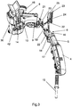
- the Figures 1 to 3 and 5 represent a steam hair treatment apparatus comprising a housing 1 made of plastic material having a body 2 extended downwards by an elongated portion forming a handle 3 receiving a removable water tank 4 whose upper wall constitutes the upper part of the handle.
- the elongated portion of the housing 1 also contains means 6 for supplying a steam generator contained in the body 2 of the housing 1, in particular an electric pump 5 visible to the figure 3 , whose activation is controlled by a control button 7.
- the body 2 of the housing 1 encloses a steam generator 8 constituted by an instantaneous vaporization chamber 10, associated with an electric heating element 9, these elements being visible at the figure 3 .
- the flash chamber 10 generally includes a closed compartment provided with a plurality of baffles for fluid flow from a water inlet to the steam outlet ports of the chamber.
- the electrical power supply of the apparatus is done by a power cord 15.
- the electric pump 5 comprises an inlet orifice 16 connected by a first conduit 17 to the tank 4 and a discharge orifice 18 sending the water from the tank 4 through a supply circuit of the steam generator 8.
- the supply circuit of the steam generator 8 comprises a second conduit 19 leading to a branch branch dividing the supply circuit into a first pipe branch 20 connected to an inlet port 21 in the vaporization chamber 10 of the steam generator 8 and a second pipe branch 22 connected to the tank 4 allowing the discharge of a part of water from the pump 5 to the tank 4.
- the passage section of the first pipe branch 20 is smaller than that of the second pipe branch 22 which is, it, made of a flexible pipe, the device further comprising an adjusting device 23 for the flow of water supplied to the interior of the generator 8.
- the adjusting device 23 comprises means for compressing the flexible pipe of the second branch 22 which passes through a cylindrical casing 25. More particularly, the adjusting device 23 makes it possible, by turning a knurled knob 24, to actuate an internal bent lever to the housing 25, which lever is supported on the outer surface of the pipe ouple.
- the pump 5 When the pump 5 is turned on by means of the control knob 7, the latter sucks the water from the tank 4 through the first conduit 17 and delivers the water through the second conduit 19, the flow of water sent by this circuit being then divided between a first weak stream sent to the generator 8 and a larger flow sent to the tank.
- the knob 24 is rotated to compress the return pipe to the tank 4.
- the flow of water arriving inside the vaporization chamber 10 is rapidly transformed into vapor by the latter during its path along the baffles of the instantaneous vaporization chamber 10.
- the vapor exits the vaporization chamber 10 by several orifices provided on a bottom wall of the vaporization chamber located opposite the one receiving the inlet orifice 21.
- the steam outlet ports of the vaporization chamber 10 each communicate with a conduit 14 allowing distribute the steam to the outside of the appliance. So, we can notice at the figure 3 , five ducts 14 of short length, for example of about 1 cm each, allowing the steam to be distributed immediately after the exit of the vaporization chamber 10.
- the body 2 of the casing 1 is closed, in its lower part and opposite the handle 3, by a flat face 11 having a plurality of steam distribution orifices 12, each orifice communicating with the outlet of a duct 14.
- the steam distribution ports 12 are adjacent to a hair shaping device.
- the upper part of the body 2 advantageously receives the shaping device 30, the latter comprising at least one treatment surface 31 located in the extension, or even set back a few mm, parallel to the flat face 11 of the casing 1.
- the shaping device 30 is better visible at the figure 4 and it comprises two arms 33,34 mounted articulated around a hinge 35 being held in the open position or, in a variant, in the closed position by a compression spring (not visible in the drawings).
- the lower arm 34 also has, at its free end, an introduction shoe 37 of flared shape extending through a planar treatment surface 32 of rectangular shape in contact with a heating element.
- Each treatment surface 31, 32 is formed of a metal plate coming into thermal contact with an electric heating element (not visible in the drawings), which may be a resistive, PTC, infrared emitting heater, etc., which is placed against the treatment surface and inside a body 38, respectively 39 plastic of each arm 33,34.
- an electric heating element not visible in the drawings
- PTC resistive, PTC, infrared emitting heater, etc.
- the steam generator 8 comprises a heating element 9 which is thermally independent of each treatment surface 31, 32 which each comprises its own heating element.
- Each electric heating element has its own control means and is supplied with electrical power by a power cord 40.
- the heating element is provided for heating the plates in a temperature range of 90 ° C to 230 ° C.
- the apparatus comprises a single power cord 15 for supplying electrical energy to the steam generator 8 and the heating plates of the shaping device 30.
- the treatment surface 31, 32 is made of a thermally conductive material, being polished, optionally covered with an enamel, a ceramic material, a layer of glass, etc.
- the arms 33,34 are thus elastically movable in pivoting about an axis perpendicular to the longitudinal direction of their respective processing surfaces 31,32 between an open position and a closed position.
- a lock of hair can be inserted between the treatment surfaces 31, 32 of the arms 33, 34 when the arms are in the open position and can then be subjected to pressure to come into contact with the treatment surfaces.
- the closure can be performed by pressing on the outer surface of the bodies 38,39 of the arms.
- the flat 31,32 treatment surfaces thus smooth the wick with which they come into contact.
- the jaws are closed at rest and the insertion of the wick is manually forced between the plates of the treatment surfaces 31, 32 by stretching the wick and pushing between the two plates using the introduction shoes 36,37.
- a system for controlling the opening of the plates to separate them sufficiently in such a way as to simplify the introduction of the wick, the actuation being able for example to be done from the handle of the apparatus or close to that -this.
- the lower arm 34 comprises a deflector 42 comprising a wall 43 arranged in recess, but parallel to the treatment surface 32.
- the wall 43 forms a vapor barrier protecting the scalp from the action of the steam by making it possible to return the steam towards the lock of hair treated.
- This vapor return also has the advantage of impregnating the wick on both sides by having only a unilateral steam outlet.
- the upper arm 33 comprises a fixing support 45 to the body 2 of the housing 1 of the apparatus, more particularly a removable attachment by means of a screw 46 cooperating with a threaded orifice in the upper part of the body 2 of the device.
- This removable attachment then allows, by loosening the screw 46, to move from a position as illustrated in the figures, suitable for use by a right-handed person, to another where the device is rotated 180 ° around the longitudinal axis of the body 2 for the use of the device by a left-handed person.
- This shaping device can be replaced by another, for example, having a cylindrical winding body cooperating with a pivoting hair clip, this device then being introduced into the mounting bracket 45 and mounted on the body 2 of the housing 1 of the device.
- the figure 5 illustrates an alternative embodiment of the deflector 42, in particular by making it integral with the body 2 of the housing 1 of the device.
- the deflector 42 has a general tuning fork shape with a bottom wall 44 through which the dispensing orifices 12 pass, extending through a bend connecting it to a deflecting wall 43 spaced apart.
- the deflecting wall 43 is located at a distance parallel to the bottom wall 44 and ends with an end curved towards the latter.
- Such a deflector allows the passage of a lock of hair between its parallel walls while protecting the scalp, and at the same time ensures the return of steam through the baffle wall towards the wick.
- Such a deflector may advantageously be made of a plastic material.
- the hair shaping device is started by pressing a control button and a light (no shown in the drawings) can indicate when the hotplates have reached the correct temperature.
- a lock of hair is then introduced into the arms 33, 34 of the shaping device 30 applying a pressing force to the wick, and then the control button 7 is pressed, the apparatus starting to produce hair. steam instantly.
- the apparatus is then moved along the wick and vapor treatment is performed immediately followed by smoothing by contact with the treatment surfaces 31, 32 of the shaping device.
- control means of the device are independent of those of the device, it can also be used with the smoothing plates at room temperature or very weakly heated. This allows in particular to achieve cleaning of the wick by removing impurities and moisturizing at the same time.
- the steam distribution orifices are located above the shaping device to begin with a smoothing before the steam treatment.
Description
La présente invention concerne un appareil qui effectue un traitement et/ou une mise en forme de la chevelure en utilisant des moyens de production de la vapeur et un dispositif de mise en forme chauffant prévu pour démêler, coiffer ou retenir les cheveux en relation avec la vapeur.The present invention relates to an apparatus which performs treatment and / or shaping of the hair using steam generating means and a heating shaping device for detangling, styling or holding the hair in relation to the hair. steam.
On connaît des appareils réalisant un traitement des cheveux à la vapeur tels que par exemple décrits dans le document
Le but de la présente invention est de remédier au moins en partie à ces inconvénients et de proposer un appareil de traitement des cheveux apte à communiquer rapidement, de manière efficace et uniforme, une humidité contrôlée à la chevelure traitée, tout en pouvant la dissocier d'un éventuel apport supplémentaire de chaleur et/ou mécanique de traction et/ou chimique.The object of the present invention is to remedy at least in part these drawbacks and to provide a hair treatment device able to communicate quickly, efficiently and uniformly, a controlled humidity to the treated hair, while being able to dissociate it from the hair. any additional supply of heat and / or mechanical traction and / or chemical.
Un autre but de l'invention est un appareil de traitement des cheveux à la vapeur pouvant être utilisé efficacement dans une pluralité de procédés de mise en forme de la chevelure, en étant apte à fournir la vapeur de manière homogène à la chevelure, tout en ayant une structure simplifiée et un fonctionnement sécuritaire.Another object of the invention is a hair treatment apparatus at the vapor that can be used effectively in a plurality of hair shaping processes, being able to provide the steam evenly to the hair, while having a simplified structure and safe operation.
Un autre but de l'invention est un appareil de traitement des cheveux à la vapeur qui soit fiable en fonctionnement, qui soit apte à éviter les phénomènes de condensation, tout en pouvant être réalisé de manière simple et économique.Another object of the invention is a steam hair treatment apparatus which is reliable in operation, which is able to avoid condensation phenomena, while being able to be achieved simply and economically.
Ces buts sont atteints avec un appareil de traitement des cheveux à la vapeur comportant un boîtier comprenant un réservoir de liquide, des moyens d'alimentation en liquide d'un générateur de vapeur, un ou plusieurs orifices de distribution de la vapeur produite en direction d'une mèche de cheveux et un dispositif de mise en forme des cheveux sous forme de pince de lissage comprenant deux bras articulés mobiles dans des directions opposées, comportant chacun une surface de traitement des cheveux, au moins l'un des bras comportant un élément chauffant en contact thermique avec ladite surface de traitement venant au contact d'une mèche de cheveux, caractérisé en ce que le générateur de vapeur comporte un élément chauffant dédié à la production de vapeur et qui est thermiquement indépendant de chaque surface de traitement, c'est à dire que ledit élément chauffant est séparé du dispositif de mise en forme, chaque surface de traitement comportant chacune son propre élément chauffant, et en ce que le ou les orifices de distribution de vapeur sont adjacents au dispositif de mise en forme des cheveux et agencés au voisinage de la bordure du dispositif de mise en forme. Par dispositif de mise en forme des cheveux on comprend un dispositif apte à venir au moins temporairement et/ou localement en contact avec les cheveux pour les démêler, les coiffer ou simplement les retenir au contact d'une surface de traitement, tels que par exemple : une pince de lissage à bras articulés mobiles ou fixes, un fer à friser à mandrin cylindrique chauffant coopérant éventuellement avec au moins une plaque chauffante en vis-à-vis, une tête de lissage comportant plusieurs surfaces parallèles de traitement côte à côte, etc.These objects are achieved with a steam hair treatment apparatus comprising a housing comprising a liquid reservoir, means for supplying liquid to a steam generator, or one or more steam dispensing orifices produced in the direction of a lock of hair and a device for shaping the hair in the form of a smoothing pincer comprising two articulated arms movable in opposite directions, each having a hair treatment surface, at least one of the arms comprising a heating element in thermal contact with said treatment surface coming into contact with a lock of hair, characterized in that the steam generator comprises a heating element dedicated to the production of steam and which is thermally independent of each treatment surface, it is to say that said heating element is separated from the shaping device, each treatment surface each having its own heating element, and in that the one or more vapor distribution orifices are adjacent to the hair shaping device and arranged in the vicinity of the edge of the shaping device. Hair shaping device comprises a device capable of coming at least temporarily and / or locally in contact with the hair to untangle, capping or simply retain them in contact with a treatment surface, such as for example : a smoothing pliers with movable or fixed articulated arms, a curling iron with a cylindrical heating mandrel possibly cooperating with at least one heating plate facing each other, a smoothing head comprising several parallel surfaces of treatment side by side, etc. .
Par thermiquement indépendant, on comprend un générateur de vapeur muni d'un élément chauffant dédié à la production de vapeur, séparé du dispositif de mise en forme qui comporte un élément chauffant propre.By thermally independent, there is a steam generator provided with a heating element dedicated to the production of steam, separated from the shaping device which comprises a clean heating element.
Le générateur de vapeur ainsi réalisé, permet de fournir de manière instantanée un débit de vapeur important et en continu à la mèche traitée, et ceci indépendamment de la température de la surface de traitement, même pour une température basse de la surface de traitement. Ceci pour ainsi aboutir à un traitement durable et en profondeur de la mèche traitée, par exemple un lissage, un bouclage, un gaufrage de celle-ci.The steam generator thus produced makes it possible to provide instant a large flow of steam and continuously treated wick, and this regardless of the temperature of the treatment surface, even for a low temperature of the treatment surface. This to result in a durable and deep treatment of the treated lock, for example a smoothing, looping, embossing thereof.
En effet, il a été constaté que le traitement de la mèche au moyen d'un dispositif réalisant une action thermique, en plus de celle mécanique, après l'application de la vapeur, empêche la déshydratation du cheveu, celui-ci étant préalablement gainé d'une couche humide. Cette gaine est, certes évaporée au moment de l'action de coiffage, mais en lieu et place de l'eau contenue au coeur du cheveu qui est ainsi protégé de toute déshydratation liée à l'application d'un dispositif de mise en forme chaud.Indeed, it has been found that the treatment of the wick by means of a device performing a thermal action, in addition to the mechanical one, after the application of steam, prevents the dehydration of the hair, the latter being previously sheathed a wet layer. This sheath is, of course, evaporated at the time of the styling action, but instead of the water contained in the heart of the hair which is thus protected from dehydration related to the application of a hot shaping device .
De la même manière, lorsque l'on applique la vapeur à une mèche de cheveux après la mise en forme par un dispositif réalisant une action thermique, voire, combinée à une action mécanique sur la mèche, la vapeur vient réhydrater le cheveu pour compenser la déshydratation liée à l'application sur le cheveu d'un outil chaud.In the same way, when the steam is applied to a lock of hair after shaping by a device performing a thermal action, or combined with a mechanical action on the wick, the steam rehydrates the hair to compensate for the dehydration related to the application on the hair of a hot tool.
Par orifices de distribution adjacents au dispositif de mise en forme des cheveux, on comprend un ou plusieurs orifices de sortie de vapeur agencés au voisinage de la bordure du dispositif de mise en forme, c'est-à-dire à côté et au plus près de l'entrée ou de la sortie de la mèche de cheveux du dispositif réalisant la mise en forme.By dispensing orifices adjacent to the hair shaping device, one or more steam outlet orifices are arranged in the vicinity of the edge of the shaping device, that is to say on the side and as close as possible. of the entry or the exit of the hair lock of the device carrying out the shaping.
Par un tel agencement on exclut donc l'arrivée de la vapeur à l'intérieur du dispositif afin de bien séparer la fonction de traitement à la vapeur d'une autre fonction de mise en forme des cheveux, qui peut être, par exemple, un traitement par application de chaleur, et/ou d'une tension ou pression sur les cheveux, et/ou d'un produit de mise en forme de la chevelure, par exemple un agent de fixation etc.By such an arrangement, therefore, the arrival of the steam inside the device is excluded in order to separate the steam treatment function from another hair shaping function, which may be, for example, a treatment by applying heat, and / or a voltage or pressure on the hair, and / or a shaping product of the hair, for example a fixing agent and so on.
En effet, il a été constaté lors de nombreux tests effectués en laboratoire que, en envoyant un débit contrôlé de vapeur soit sur des mèches de cheveux à l'état naturel, soit sur des mèches de cheveux enduites de cosmétique, l'on obtenait de bien meilleurs résultats lorsque l'on dissociait l'application de la vapeur de celle d'un autre traitement sur la mèche testée. Ainsi, les tests ont montré que la vapeur permettait, à elle seule, déjà de bien préparer les cheveux à un traitement ultérieur, par exemple en les nettoyant et en les chargeant uniformément en humidité. Il a été également constaté qu'en envoyant de la vapeur après une mise en forme, les cheveux sont chargés de manière mieux contrôlée en humidité et ils gardent d'autant plus longtemps leur mise en forme, avec des résultats remarquables sur leur aspect, notamment la brillance, la couleur, et ceci de manière homogène dans tout leur volume.In fact, it has been observed in numerous tests carried out in the laboratory that, by sending a controlled flow of steam either on strands of hair in the natural state, or on strands of hair coated with cosmetics, it was possible to obtain much better results when dissociating the application of steam from that of another treatment on the wick tested. For example, tests have shown that steam alone can already prepare the hair for further processing, for example by cleaning and evenly loading it with moisture. It has also been found that by sending steam after shaping, the hair is loaded in a more controlled manner in moisture and they keep their shaping even longer, with remarkable results on their appearance, especially the brilliance, the color, and this in a homogeneous way in all their volume.
De préférence, l'appareil de l'invention comprend un déflecteur agencé en vis-à-vis du ou des orifices de distribution.Preferably, the apparatus of the invention comprises a deflector arranged vis-à-vis the or orifices of distribution.
Ce déflecteur fonctionne comme un pare vapeur en étant placé en vis-à-vis de la sortie de vapeur pour, d'une part, protéger le cuir chevelu de la personne sur laquelle est réalisé le traitement et, d'autre part, pour rediriger la vapeur vers le dos de la mèche et ainsi la traiter sur ses deux faces avec une sortie de vapeur située seulement sur un côté de celle-ci. Ce déflecteur peut appartenir au boîtier de l'appareil ou être solidaire du dispositif de mise en forme.This deflector functions as a vapor barrier being placed vis-à-vis the steam outlet to, firstly, protect the scalp of the person on whom the treatment is performed and, secondly, to redirect steam to the back of the wick and treat it on both sides with a steam outlet located only on one side of it. This deflector may belong to the housing of the device or be integral with the formatting device.
Avantageusement, le cheminement de vapeur se fait via plusieurs orifices uniformément distribués parallèlement à la surface de traitement de forme générale allongée du dispositif de mise en forme orientant la vapeur dans une direction perpendiculaire à celle de leur mise en forme par ledit dispositif.Advantageously, the steam path is via several orifices uniformly distributed parallel to the generally elongate processing surface of the forming device orienting the vapor in a direction perpendicular to that of their shaping by said device.
La direction de la mise en forme est définie généralement par la surface de traitement de forme générale allongée du dispositif de mise en forme, surface qui traite généralement avec son côté le plus long la largeur d'une mèche. Un cheminement de vapeur arrivant perpendiculairement à la largeur d'une mèche permet ainsi un traitement rapide de la mèche de cheveux et, de surcroît, homogène lorsque l'on distribue la vapeur par des orifices de sortie couvrant la largeur de la mèche.The direction of the shaping is defined generally by the generally elongated surface of the shaping device, surface which generally treats with its longest side the width of a wick. A vapor path arriving perpendicular to the width of a wick thus allows a quick treatment of the lock of hair and, moreover, homogeneous when the steam is distributed through outlet openings covering the width of the wick.
De préférence, le générateur de vapeur comprend une chambre de vaporisation en contact thermique avec un élément chauffant électrique et l'appareil comporte un ou plusieurs conduits reliant la sortie de la chambre de vaporisation à l'orifice ou aux orifices de distribution ayant chacun une longueur inférieure à 3 cm.Preferably, the steam generator comprises a vaporization chamber in thermal contact with an electric heating element and the apparatus comprises one or more conduits connecting the outlet of the vaporization chamber to the orifice or to the dispensing orifices each having a length less than 3 cm.
De préférence, l'appareil est portatif, ce qui permet d'avoir la sortie de la vapeur agencée au plus près des moyens de génération de vapeur du boîtier pour éliminer les phénomènes de condensation, tout en simplifiant la construction de l'appareil et en rendant plus souple son maniement.Preferably, the apparatus is portable, which makes it possible to have the outlet of the steam arranged as close as possible to the steam generation means of the housing in order to eliminate condensation phenomena, while simplifying the construction of the apparatus and making its handling more flexible.
La chambre de vaporisation est ainsi positionnée au plus près des orifices de distribution ou de sortie de la vapeur, ce qui permet de traiter la mèche de cheveux directement en sortie de la chambre de vaporisation, via un ou plusieurs conduits. Ces conduits de vapeur en sortie de la chambre de vaporisation étant donc de longueur très courte répartissent la vapeur sans qu'il ne puisse se constituer des condensats qui pourraient alors perturber et/ou annuler l'action de la vapeur sur la mèche ou nuire à la facilité d'usage de l'appareil, les condensats pouvant à la limite brûler la personne utilisant l'appareil.The vaporization chamber is thus positioned as close as possible to the steam distribution or outlet orifices, which makes it possible to treat the lock of hair directly at the outlet of the vaporization chamber, via one or more conduits. These steam ducts leaving the vaporization chamber therefore being of very short length distribute the vapor without it being possible to form condensates which could then disturb and / or cancel the action of the steam on the wick or damage to the ease of use of the device, the condensates can limit the person using the device.
Avantageusement, le générateur de vapeur produit un débit de vapeur supérieur à 5g/min, de préférence compris entre 10g/min et 60g/min.Advantageously, the steam generator produces a steam flow rate greater than 5 g / min, preferably between 10 g / min and 60 g / min.
Les appareils de traitement des cheveux à la vapeur connus ne produisent qu'un assez faible débit de vapeur qui n'assure pas d'effet visible et/ou durable sur les cheveux. L'appareil de l'invention réalise un traitement efficace de la chevelure lorsque le débit de vapeur produit est supérieur à 5g/min et lorsqu'il est, de préférence compris entre 10g/min et 60g/min.The known steam hair treatment apparatus produce only a relatively small flow of steam which does not provide visible and / or lasting effect on the hair. The apparatus of the invention provides an effective treatment of the hair when the flow rate of steam produced is greater than 5g / min and when is preferably between 10g / min and 60g / min.
De préférence, l'appareil comprend un dispositif de réglage pour ajuster le débit de liquide envoyé vers le générateur.Preferably, the apparatus comprises an adjusting device for adjusting the flow of liquid to the generator.
Un tel dispositif de réglage du débit de liquide envoyé par la pompe dans la chambre de vaporisation permet d'adapter le débit de vapeur produit au type de traitement et/ou au type de cheveu traité avec l'appareil.Such a device for adjusting the flow rate of liquid sent by the pump into the vaporization chamber makes it possible to adapt the flow of steam produced to the type of treatment and / or the type of hair treated with the apparatus.
De préférence, le dispositif de mise en forme comporte des moyens de commande des moyens de chauffage de la surface de traitement indépendants des moyens de commande de la vapeur.Preferably, the shaping device comprises means for controlling the heating means of the treatment surface independent of the steam control means.
Ceci permet de bien dissocier les deux fonctions, tout en permettant d'ajuster les paramètres de fonctionnement de chaque fonction indépendamment.This allows to separate the two functions, while allowing to adjust the operating parameters of each function independently.
Avantageusement, le dispositif de mise en forme est agencé de manière amovible par rapport au boîtier de l'appareil.Advantageously, the shaping device is removably arranged relative to the housing of the apparatus.
Ceci permet l'utilisation ambidextre de l'appareil avec un même dispositif, voire avec une pluralité de dispositifs de mise en forme, de manière simple et peu coûteuse.This allows the ambidextrous use of the apparatus with the same device, or even with a plurality of formatting devices, in a simple and inexpensive way.
De préférence, le liquide contenu dans le réservoir est un produit de traitement.Preferably, the liquid contained in the reservoir is a treatment product.
Par liquide de traitement on comprend tout liquide apte à être vaporisé par le générateur et pouvant ensuite être appliqué sur les cheveux sous forme de vapeur pour en assurer un soin, une mise en forme, une coloration une décoloration, etc. Dans un mode préféré de réalisation de l'invention, ce liquide est l'eau.By treatment liquid is understood any liquid capable of being vaporized by the generator and which can then be applied to the hair in the form of steam to ensure care, shaping, coloring, discoloration, etc. In a preferred embodiment of the invention, this liquid is water.
Dans un autre mode de réalisation de l'invention, l'appareil comprend un réservoir supplémentaire de liquide adjacent au dispositif de mise en forme des cheveux ou appartenant à celui-ci.In another embodiment of the invention, the apparatus comprises an additional reservoir of liquid adjacent to the shaping device of the hair or belonging to it.
Ce réservoir supplémentaire peut donc appartenir à l'appareil ou au dispositif de mise en forme et permet d'appliquer à la chevelure un liquide qui ne soit pas forcement vaporisé par le générateur de vapeur de l'appareil, par exemple lors d'une application par contact du liquide provenant du réservoir supplémentaire avec la mèche traitée.This additional reservoir can therefore belong to the apparatus or to the shaping device and makes it possible to apply to the hair a liquid that is not necessarily vaporized by the steam generator of the apparatus, for example during an application by contacting the liquid from the additional reservoir with the treated wick.
Avantageusement, le liquide contenu dans le réservoir supplémentaire est différent du liquide contenu dans le réservoir qui alimente le générateur de vapeur.Advantageously, the liquid contained in the additional reservoir is different from the liquid contained in the reservoir that supplies the steam generator.
Ceci permet d'appliquer un liquide cosmétique, par exemple de mise en forme ou de coloration, en plus du traitement à la vapeur.This makes it possible to apply a cosmetic liquid, for example shaping or coloring, in addition to the steam treatment.
Ainsi, dans le cas où le cosmétique a été déposé avant l'application de la vapeur, la vapeur sert de média de transport du cosmétique pour le faire pénétrer à coeur du cheveu via l'ouverture des écailles, le traitement mécanique qui suit permettant de refermer les écailles et de réaliser une forme de cautérisation du cheveu pour fixer le cosmétique.Thus, in the case where the cosmetic has been deposited before the application of the steam, the steam serves as a transport medium for the cosmetic to make it penetrate to the heart of the hair via the opening of the scales, the following mechanical treatment allowing close the scales and perform a form of cauterization of the hair to fix the cosmetic.
Par ailleurs, dans le cas où le cosmétique a été déposé après le traitement mécanique et thermique du cheveu, la vapeur est utilisée comme média de transport, tout en évitant de soumettre le cosmétique à de très hautes températures et éviter ainsi qu'il soit détérioré par la température.Moreover, in the case where the cosmetic has been deposited after the mechanical and thermal treatment of the hair, the steam is used as a transport medium, while avoiding to subject the cosmetic to very high temperatures and thus prevent it from being damaged by the temperature.
Dans une première variante de réalisation de l'invention, lesdits orifices de distribution sont adjacents au dispositif de mise en forme des cheveux en étant situés en amont de celui-ci.In a first embodiment of the invention, said dispensing orifices are adjacent to the hair shaping device being located upstream thereof.
Par « en amont », on entend que dans l'opération de traitement, une portion de la mèche de cheveux supporte d'abord l'application de la vapeur avant de supporter le traitement de mise en forme.By "upstream" is meant that in the treatment operation, a portion of the lock of hair first supports the application of steam before supporting the shaping treatment.
Les tests effectués en traitant une mèche de cheveux avec de la vapeur envoyée en amont du dispositif de mise en forme ont montré que la vapeur arrive à ouvrir les écailles du cheveu, le nettoie en profondeur. L'action mécanique effectuée ensuite par le dispositif de mise en forme finit de débarrasser le cheveu des impuretés provenant par exemple d'un éventuel traitement et/ou soin antérieur.Tests carried out by treating a lock of hair with steam sent upstream of the shaping device showed that the steam manages to open the scales of the hair, cleans it in depth. The mechanical action then performed by the shaping device finishes to rid the hair of impurities resulting for example from a possible treatment and / or previous care.
Les tests en laboratoire ont aussi montré que la vapeur envoyée en amont du dispositif de mise en forme lorsque celui-ci comporte un système de distribution de cosmétique, permet de faciliter la pénétration dudit cosmétique à l'intérieur du cheveu, cela conduisant à une meilleure action en profondeur dudit cosmétique.Laboratory tests have also shown that the steam sent upstream of the shaping device when it includes a cosmetic dispensing system, facilitates the penetration of said cosmetic inside the hair, which leads to better in-depth action of said cosmetic.
Il a aussi été constaté que le traitement de la mèche au moyen d'un dispositif réalisant une action thermique, en plus de celle mécanique, après l'application de la vapeur, empêche la déshydratation du cheveu, celui-ci étant préalablement gainé d'une couche humide. Cette gaine est, certes évaporée au moment de l'action de coiffage, mais en lieu et place de l'eau contenue au coeur du cheveu qui est ainsi protégé de toute déshydratation liée à l'application d'un dispositif de mise en forme chaud.It has also been found that the treatment of the wick by means of a device performing a thermal action, in addition to the mechanical one, after the application of steam, prevents the dehydration of the hair, the latter being previously sheathed with a wet layer. This sheath is, of course, evaporated at the time of the styling action, but instead of the water contained in the heart of the hair which is thus protected from dehydration related to the application of a hot shaping device .
Enfin, les tests en laboratoire ont aussi montré que la vapeur envoyée en amont du dispositif de mise en forme permet de charger suffisamment le cheveu en humidité pour le protéger d'une déshydratation importante lors de l'action du dispositif de mise en forme qui peut être chauffé à haute température, par exemple 230°C.Finally, the laboratory tests have also shown that the steam sent upstream of the shaping device can sufficiently load the hair in moisture to protect it from significant dehydration during the action of the shaping device that can be heated at high temperature, for example 230 ° C.
Dans une deuxième variante de réalisation de l'invention, lesdits orifices de distribution sont adjacents au dispositif de mise en forme des cheveux en étant situés en aval de celui-ci.In a second variant embodiment of the invention, said dispensing orifices are adjacent to the hair shaping device while being located downstream thereof.
Par « en aval », on entend que dans l'opération de traitement, une portion de la mèche de cheveux supporte d'abord le traitement de mise en forme avant de supporter l'application de vapeur.By "downstream" is meant that in the treatment operation, a portion of the Strand of hair initially supports the shaping treatment before supporting the application of steam.
Les tests effectués avec un appareil réalisé selon cette variante de l'invention ont montré que, après une mise en forme mécanique de la mèche, la vapeur vient réhydrater le cheveu pour compenser la déshydratation liée à l'application sur le cheveu de la surface de traitement chaude d'un dispositif de mise en forme.Tests carried out with an apparatus made according to this variant of the invention have shown that, after mechanical shaping of the wick, the steam rehydrates the hair to compensate for the dehydration associated with the application to the hair of the surface of the hair. hot treatment of a shaping device.
Avantageusement, le boîtier comprend un corps se prolongeant vers le bas par une poignée, le dispositif de mise en forme étant agencé à l'opposé de la poignée et le cheminement de vapeur sortant par les orifices de distribution est orienté selon la direction longitudinale du corps du boîtier.Advantageously, the housing comprises a body extending downwards by a handle, the shaping device being arranged opposite the handle and the steam path exiting through the dispensing orifices is oriented in the longitudinal direction of the body of the case.
Une telle configuration de boîtier assure à la fois une bonne ergonomie en utilisation et un traitement efficace de la chevelure par la vapeur. D'après l'invention, le dispositif de mise en forme des cheveux comprend deux bras articulés, mobiles dans des directions opposées, comportant chacun une surface de traitement des cheveux, au moins l'un des bras comportant un élément chauffant en contact thermique avec ladite surface de traitement.Such a housing configuration provides both good ergonomics in use and effective treatment of the hair by steam. According to the invention, the hair shaping device comprises two articulated arms, movable in opposite directions, each having a hair treatment surface, at least one of the arms having a heating element in thermal contact with each other. said treatment surface.
Un tel dispositif assure un lissage efficace des cheveux, avec une bonne tenue dans le temps.Such a device provides effective smoothing of the hair, with good performance over time.
Dans une optique d'ergonomie, les bras articulés sont montés pivotants autour d'un axe sensiblement parallèle à celui de la poignée de l'appareil.In an ergonomic perspective, the articulated arms are pivotally mounted about an axis substantially parallel to that of the handle of the apparatus.
L'invention sera mieux comprise à l'étude d'un mode particulier de réalisation de l'invention pris à titre nullement limitatif et illustré dans les figures annexées dans lesquelles :
- la
figure 1 est une vue en perspective d'un appareil de traitement des cheveux à la vapeur selon un mode particulier de réalisation de l'invention, le dispositif de mise en forme étant en position fermée ; - la
figure 2 est une vue en perspective de l'appareil de lafigure 1 , le dispositif de mise en forme étant en position ouverte ; - la
figure 3 est une vue en perspective de l'appareil de lafigure 1 , dépourvu de son boîtier enveloppe ; - la
figure 4 est une vue en perspective d'un dispositif de mise en forme de l'appareil des figures précédentes ; - la
figure 5 est une vue en perspective de l'appareil de traitement des cheveux à la vapeur selon une variante du mode de réalisation de lafigure 1 .
- the
figure 1 is a perspective view of a device for processing steam hair according to a particular embodiment of the invention, the shaping device being in the closed position; - the
figure 2 is a perspective view of the device from thefigure 1 the shaping device being in the open position; - the
figure 3 is a perspective view of the device from thefigure 1 , devoid of its casing envelope; - the
figure 4 is a perspective view of a shaping device of the apparatus of the preceding figures; - the
figure 5 is a perspective view of the steam hair treatment apparatus according to a variant of the embodiment of thefigure 1 .
Les
A la
Lors de la mise en route de la pompe 5 au moyen du bouton de commande 7, celle-ci aspire l'eau du réservoir 4 par le premier conduit 17 et refoule l'eau par le second conduit 19, le flux d'eau envoyé par ce circuit étant alors divisé entre un premier flux faible envoyé vers le générateur 8 et un flux plus important envoyé vers le réservoir. Pour augmenter le flux d'eau envoyé vers le générateur 8, on tourne le bouton 24 pour comprimer le tuyau de retour vers le réservoir 4.When the
Le flux d'eau arrivant à l'intérieur de la chambre de vaporisation 10 est rapidement transformé en vapeur par celle-ci lors de son cheminement le long des chicanes de la chambre de vaporisation instantanée 10. La vapeur sort de la chambre de vaporisation 10 par plusieurs orifices pratiqués sur une paroi de fond de la chambre de vaporisation située à l'opposée de celle recevant l'orifice d'admission 21. Les orifices de sortie de vapeur de la chambre de vaporisation 10 communiquent chacun avec un conduit 14 permettant de distribuer la vapeur à l'extérieur de l'appareil. Ainsi, on peut remarquer à la
Tel que mieux visible à la
Les orifices de distribution de vapeur 12 sont adjacents à un dispositif de mise en forme 30 des cheveux. Ainsi, la partie supérieure du corps 2 reçoit avantageusement le dispositif de mise en forme 30, ce dernier comprenant au moins une surface de traitement 31 située dans le prolongement, voire en retrait de quelques mm, parallèlement à la face plane 11 du boîtier 1.The
Le dispositif de mise en forme 30 est mieux visible à la
Chaque surface de traitement 31,32 est formée d'une plaque métallique venant en contact thermique avec un élément chauffant électrique (non visible sur les dessins), qui peut être un élément chauffant résistif, à CTP, à émission infrarouge, etc., qui est placé contre la surface de traitement et à l'intérieur d'un corps 38, respectivement 39 en matière plastique de chaque bras 33,34.Each
Ainsi selon l'invention, le générateur de vapeur 8 comporte un élément chauffant 9 qui est thermiquement indépendant de chaque surface de traitement 31, 32 qui comporte chacune son propre élément chauffant.Thus according to the invention, the
Chaque élément chauffant électrique comporte ses propres moyens de régulation et est alimenté en énergie électrique par un cordon d'alimentation 40. L'élément chauffant est prévu pour chauffer les plaques dans une plage de températures allant de 90°C à 230°C. Dans une variante, l'appareil comporte un cordon d'alimentation 15 unique permettant de fournir l'énergie électrique au générateur de vapeur 8 et aux plaques chauffantes du dispositif de mise en forme 30. La surface de traitement 31,32 est réalisée en un matériau thermiquement conducteur, en étant polie, éventuellement recouverte d'un émail, d'un matériau céramique, d'une couche de verre, etc.Each electric heating element has its own control means and is supplied with electrical power by a
Les bras 33,34 sont ainsi mobiles élastiquement en pivotement autour d'un axe perpendiculaire à la direction longitudinale de leurs surfaces de traitement respectives 31,32 entre une position d'ouverture et une position de fermeture. Ainsi, une mèche de cheveux peut être insérée entre les surfaces de traitement 31,32 des bras 33,34 lorsque les bras sont en position d'ouverture et elle peut être ensuite soumise à une pression pour venir en contact avec les surfaces de traitement 31,32 lorsque les bras sont en position de fermeture, la fermeture pouvant être réalisée par appui sur la surface extérieure des corps 38,39 des bras. Les surfaces de traitement 31,32 planes réalisent ainsi un lissage de la mèche avec laquelle elles viennent en contact.The
Dans une autre variante de réalisation du dispositif de mise en forme 30, les mâchoires sont fermées au repos et l'on vient forcer manuellement l'introduction de la mèche entre les plaques des surfaces de traitement 31,32 en tendant la mèche et en la poussant entre les deux plaques à l'aide des sabots d'introduction 36,37. Avantageusement, on peut envisager un système de commande de l'ouverture des plaques pour les écarter suffisamment de manière à simplifier l'introduction de la mèche, l'actionnement pouvant par exemple se faire depuis la poignée de l'appareil ou à proximité de celle-ci.In another variant embodiment of the
Selon un aspect avantageux de l'invention, le bras inférieur 34 comporte un déflecteur 42 comportant une paroi 43 agencée en retrait, mais parallèlement à la surface de traitement 32. La paroi 43 forme un pare vapeur protégeant le cuir chevelu de l'action de la vapeur en permettant de renvoyer la vapeur en direction de la mèche de cheveux traitée. Ce renvoi de vapeur a aussi pour avantage d'imprégner la mèche sur ses deux faces en ne disposant que d'une sortie de vapeur unilatérale.According to an advantageous aspect of the invention, the
Selon un autre aspect avantageux de l'invention, le bras supérieur 33 comporte un support de fixation 45 au corps 2 du boîtier 1 de l'appareil, plus particulièrement une fixation amovible moyennant une vis 46 coopérant avec un orifice fileté dans la partie supérieure du corps 2 de l'appareil. Cette fixation amovible permet alors, en desserrant la vis 46, de passer d'un positionnement tel qu'illustré aux figures, convenant à l'utilisation par une personne droitière, à un autre où le dispositif est tourné de 180° autour de l'axe longitudinal du corps 2 pour l'utilisation de l'appareil par une personne gauchère. Ce dispositif de mise en forme peut être remplacé par un autre, par exemple, comportant un corps d'enroulement cylindrique coopérant avec une pince pivotante d'attache des cheveux, ce dispositif étant alors introduit dans le support de fixation 45 et monté sur le corps 2 du boîtier 1 de l'appareil.According to another advantageous aspect of the invention, the
La
En fonctionnement, on met en marche le dispositif de mise en forme 30 des cheveux en appuyant sur un bouton de commande et un témoin lumineux (non représentés sur les dessins) peut indiquer le moment où les plaques chauffantes ont atteint la bonne température. On introduit ensuite une mèche de cheveux à l'intérieur des bras 33,34 du dispositif de mise en forme 30 appliquant un effort de pression sur la mèche, puis on appuie sur le bouton de commande 7, l'appareil commençant à produire de la vapeur de manière instantanée. On déplace ensuite l'appareil le long de la mèche et on réalise un traitement à la vapeur suivi immédiatement d'un lissage par contact avec les surfaces de traitement 31,32 du dispositif de mise en forme.In operation, the hair shaping device is started by pressing a control button and a light (no shown in the drawings) can indicate when the hotplates have reached the correct temperature. A lock of hair is then introduced into the
Du fait que les moyens de commande du dispositif sont indépendants de ceux de l'appareil, celui-ci peut également être utilisé avec les plaques de lissage à la température ambiante ou très faiblement chauffées. Ceci permet notamment de réaliser un nettoyage de la mèche en la débarrassant d'impuretés et en l'hydratant en même temps.Because the control means of the device are independent of those of the device, it can also be used with the smoothing plates at room temperature or very weakly heated. This allows in particular to achieve cleaning of the wick by removing impurities and moisturizing at the same time.
Dans une variante non illustrée sur les dessins, les orifices de distribution de la vapeur sont situés au-dessus du dispositif de mise en forme afin de commencer par un lissage avant le traitement à la vapeur.In a variant not shown in the drawings, the steam distribution orifices are located above the shaping device to begin with a smoothing before the steam treatment.
Bien entendu, l'invention n'est nullement limitée au mode de réalisation décrit et illustré qui n'a été donné qu'à titre d'exemple. Des modifications restent possibles, notamment du point de vue de la constitution des divers éléments ou par substitution d'équivalents techniques, sans sortir pour autant du domaine de protection de l'invention.Of course, the invention is not limited to the embodiment described and illustrated which has been given by way of example. Modifications are possible, particularly from the point of view of the constitution of the various elements or by substitution of technical equivalents, without departing from the scope of protection of the invention.
Claims (10)
- Apparatus for treating hair with steam including a housing (1) comprising
a liquid container (4),
liquid supply means (6) of a steam generator (8),
one or a plurality of dispensing orifices (12) of the steam produced towards a strand of hair and
a hair styling device (30) in the form of straightening tongs comprising two hinged arms (33, 34) movable in opposite directions, each including a hair treatment surface (31, 32), at least one of the arms (33, 34) including a heating element in thermal contact with said treatment surface (31, 32) coming into contact with a strand of hair,
characterised in that
the steam generator (8) includes a heating element (9) specifically for the production of steam and which is thermally independent from each treatment surface (31,32), i.e. said heating element (9) is separate from the styling device (30), each treatment surface (31, 32) including its own heating element,
and in that the steam dispensing orifice(s) (12) are adjacent to the hair styling device (30) or arranged in the vicinity of the edge of the styling device (30). - Apparatus according to claim 1, characterised in that it comprises a baffle arranged facing the dispensing orifice(s).
- Apparatus according to one of claims 1 to 2, characterised in that the steam flows via a plurality of orifices (12) uniformly distributed parallel with the generally elongated treatment surface (31) of the styling device (30) guiding the steam in a perpendicular direction to that of the styling thereof by said device.
- Apparatus according to one of claims 1 to 3, characterised in that the steam generator (8) comprises a vaporisation chamber (10) in thermal contact with an electric heating element (9) and in that said apparatus includes one or a plurality of ducts (14) connecting the outlet of the vaporisation chamber (10) to the dispensing orifice or orifices (12) each having a length less than 3 cm.
- Apparatus according to one of the preceding claims, characterised in that the steam generator (8) produces a steam flow rate greater than 5 g/min, preferably between 10 g/min and 60 g/min.
- Apparatus according to one of the preceding claims, characterised in that it comprises a setting device (23) for adjusting the liquid flow rate sent to the generator (8).
- Apparatus according to one of the preceding claims, characterised in that the styling device (30) includes means for controlling the heating means of the treatment surface (31) independent from the steam control means.
- Apparatus according to one of the preceding claims, characterised in that the liquid contained in the container is a treatment product.
- Apparatus according to one of the preceding claims, characterised in that it comprises an additional liquid container adjacent to the hair styling device or belonging thereto.
- Apparatus according to the preceding claim, characterised in that the liquid contained in the additional container is different from the liquid contained in the container supplying the steam generator.
Priority Applications (4)
| Application Number | Priority Date | Filing Date | Title |
|---|---|---|---|
| PL08861188T PL2209395T3 (en) | 2007-10-03 | 2008-10-02 | Apparatus for the steam treatment of hair |
| PL13154490T PL2609828T3 (en) | 2007-10-03 | 2008-10-02 | Appliance for treating hair with steam with independent controls |
| EP13154491.8A EP2625981B1 (en) | 2007-10-03 | 2008-10-02 | Appliance for treating hair with steam with deflector |
| EP13154490.0A EP2609828B1 (en) | 2007-10-03 | 2008-10-02 | Appliance for treating hair with steam with independent controls |
Applications Claiming Priority (2)
| Application Number | Priority Date | Filing Date | Title |
|---|---|---|---|
| FR0706926A FR2921803B1 (en) | 2007-10-03 | 2007-10-03 | APPARATUS FOR TREATING HAIR WITH STEAM |
| PCT/FR2008/001374 WO2009077673A2 (en) | 2007-10-03 | 2008-10-02 | Apparatus for the steam treatment of hair |
Related Child Applications (4)
| Application Number | Title | Priority Date | Filing Date |
|---|---|---|---|
| EP13154491.8A Division-Into EP2625981B1 (en) | 2007-10-03 | 2008-10-02 | Appliance for treating hair with steam with deflector |
| EP13154491.8A Division EP2625981B1 (en) | 2007-10-03 | 2008-10-02 | Appliance for treating hair with steam with deflector |
| EP13154490.0A Division-Into EP2609828B1 (en) | 2007-10-03 | 2008-10-02 | Appliance for treating hair with steam with independent controls |
| EP13154490.0A Division EP2609828B1 (en) | 2007-10-03 | 2008-10-02 | Appliance for treating hair with steam with independent controls |
Publications (2)
| Publication Number | Publication Date |
|---|---|
| EP2209395A2 EP2209395A2 (en) | 2010-07-28 |
| EP2209395B1 true EP2209395B1 (en) | 2017-08-23 |
Family
ID=39434183
Family Applications (3)
| Application Number | Title | Priority Date | Filing Date |
|---|---|---|---|
| EP13154490.0A Active EP2609828B1 (en) | 2007-10-03 | 2008-10-02 | Appliance for treating hair with steam with independent controls |
| EP13154491.8A Active EP2625981B1 (en) | 2007-10-03 | 2008-10-02 | Appliance for treating hair with steam with deflector |
| EP08861188.4A Active EP2209395B1 (en) | 2007-10-03 | 2008-10-02 | Apparatus for the steam treatment of hair |
Family Applications Before (2)
| Application Number | Title | Priority Date | Filing Date |
|---|---|---|---|
| EP13154490.0A Active EP2609828B1 (en) | 2007-10-03 | 2008-10-02 | Appliance for treating hair with steam with independent controls |
| EP13154491.8A Active EP2625981B1 (en) | 2007-10-03 | 2008-10-02 | Appliance for treating hair with steam with deflector |
Country Status (10)
| Country | Link |
|---|---|
| US (1) | US9167877B2 (en) |
| EP (3) | EP2609828B1 (en) |
| JP (1) | JP5490006B2 (en) |
| KR (1) | KR101578946B1 (en) |
| CN (2) | CN101815451A (en) |
| BR (1) | BRPI0817612B1 (en) |
| ES (3) | ES2648198T3 (en) |
| FR (1) | FR2921803B1 (en) |
| PL (2) | PL2209395T3 (en) |
| WO (2) | WO2009077673A2 (en) |
Families Citing this family (22)
| Publication number | Priority date | Publication date | Assignee | Title |
|---|---|---|---|---|
| US8375610B2 (en) * | 2007-06-29 | 2013-02-19 | Patti Bearley | Handheld telescopic ironing device |
| US8136263B2 (en) * | 2007-08-21 | 2012-03-20 | Heidi Schmid | Hair care appliance and method of using same |
| US8800163B2 (en) | 2007-08-21 | 2014-08-12 | Heidi Schmid | Hair care appliance and method of using same |
| FR2921805B1 (en) * | 2007-10-03 | 2011-04-01 | Oreal | METHOD OF TREATING HAIR WITH WATER VAPOR |
| FR2943895B1 (en) * | 2009-04-03 | 2011-05-06 | Oreal | PROCESS FOR TREATING HAIR WITH WATER VAPOR. |
| US8770207B2 (en) * | 2009-11-11 | 2014-07-08 | Kao Corporation | Applicator and partial hair dyeing device |
| FR2967017B1 (en) * | 2010-11-05 | 2014-04-04 | Seb Sa | VAPOR HAIRSTYLE APPARATUS |
| FR2974485B1 (en) * | 2011-04-29 | 2014-02-28 | Seb Sa | HAND HAIRSTONE APPARATUS WITH COSMETIC PRODUCT DELIVERY SYSTEM |
| KR20130008264A (en) * | 2011-07-12 | 2013-01-22 | (주)에스비에프 | Hair iron |
| FR2987242B1 (en) | 2012-02-29 | 2014-05-23 | Seb Sa | VAPOR HAIRSTYLE APPARATUS |
| FR2997271B1 (en) * | 2012-10-26 | 2016-01-01 | Oreal | DEVICE FOR TREATING THE HAIR |
| FR3001112B1 (en) * | 2013-01-18 | 2015-03-13 | Seb Sa | STEAM HAIRSTOCK EQUIPPED WITH ELECTRONIC MANAGEMENT CARD |
| UA28306S (en) * | 2013-03-29 | 2014-11-10 | Калор | DEVICE FOR STYLING HAIR |
| GB201306718D0 (en) * | 2013-04-12 | 2013-05-29 | Ford Willcocks Harry | Eazzypress |
| FR3015876B1 (en) * | 2013-12-26 | 2016-12-30 | Oreal | DEVICE FOR TREATING THE HAIR AND RELATED RECHARGE |
| FR3046034B1 (en) * | 2015-12-23 | 2020-10-09 | Oreal | HAIR TREATMENT DEVICE |
| USD799134S1 (en) * | 2016-01-27 | 2017-10-03 | Carissa Davino | Extendable flatiron |
| USD963981S1 (en) * | 2020-06-10 | 2022-09-13 | Nori Inc. | Handheld steam iron |
| EP3935992A1 (en) * | 2020-07-10 | 2022-01-12 | Dongguan Kang Road Electrical Technology Co., Ltd. | Steam hair straightener |
| GB2612026A (en) * | 2021-10-13 | 2023-04-26 | Kuwait Innovation Center | Hair misting apparatus |
| FR3131515B1 (en) * | 2021-12-30 | 2024-01-05 | Seb Sa | HAIR STYLING DEVICE WITH HEATING AND STEAM DIFFUSION |
| FR3131514A1 (en) * | 2021-12-30 | 2023-07-07 | Seb S.A. | STEAM STYLING APPLIANCE |
Family Cites Families (35)
| Publication number | Priority date | Publication date | Assignee | Title |
|---|---|---|---|---|
| US1668430A (en) * | 1928-05-01 | Hair waver | ||
| US1455696A (en) * | 1922-09-28 | 1923-05-15 | Alice M Wright | Electric oven for hair |
| US1738916A (en) | 1927-10-26 | 1929-12-10 | Nestle Le Mur Company | Steam curling iron |
| US1836045A (en) | 1931-01-10 | 1931-12-15 | John A H Siers | Hair waving device |
| US1847735A (en) * | 1931-02-11 | 1932-03-01 | Gen Permanent Wave Corp | Method of and means for waving hair by steam heat |
| US3781519A (en) * | 1972-06-12 | 1973-12-25 | Gillette Co | Hair steamer |
| JPS5428783B2 (en) * | 1974-02-14 | 1979-09-19 | ||
| US4341229A (en) * | 1974-06-10 | 1982-07-27 | L'oreal | Method and apparatus for setting hair |
| LU70281A1 (en) * | 1974-06-10 | 1976-04-13 | ||
| US4114022A (en) | 1977-08-16 | 1978-09-12 | Braulke Iii Herbert A | Combined hot air and steam hair dryer |
| US4632133A (en) * | 1983-08-19 | 1986-12-30 | Losenno Luigi G | Method and system for the application of hair treatment solution |
| US4911185A (en) * | 1983-08-19 | 1990-03-27 | Gino, Ltd. | Method and system for the application of hair treatment solution |
| US5263501A (en) * | 1992-06-26 | 1993-11-23 | Maznik Gary R | Steam hair styling apparatus |
| US5781691A (en) * | 1996-06-24 | 1998-07-14 | Kwok; Daniel S. C. | Hand held steam dispensing hair-care apparatus |
| JPH10113212A (en) * | 1996-10-15 | 1998-05-06 | Matsushita Electric Works Ltd | Hair iron |
| US5913315A (en) | 1997-07-28 | 1999-06-22 | Todd; Mark D. | Hair tattoo apparatus and method |
| JP2000157322A (en) * | 1998-11-25 | 2000-06-13 | Matsushita Electric Works Ltd | Hairdressing iron |
| US6119702A (en) | 1999-02-26 | 2000-09-19 | Habibi; Masood | Heated hair styling system |
| JP2002253329A (en) | 2001-03-05 | 2002-09-10 | Naomoto Kogyo Kk | Hair iron |
| US20030127105A1 (en) * | 2002-01-05 | 2003-07-10 | Fontana Richard Remo | Complete compact |
| JP3402327B1 (en) | 2002-01-18 | 2003-05-06 | 松下電工株式会社 | Hair iron |
| MXPA04008975A (en) | 2002-03-15 | 2005-06-17 | Habibi Masood | Toothed heated hair styling device and method of manufacture. |
| ATE380483T1 (en) * | 2002-06-26 | 2007-12-15 | Procter & Gamble | DEVICE FOR MAINTAINING SMOOTH HAIR |
| US7178531B2 (en) * | 2002-06-26 | 2007-02-20 | The Procter & Gamble Company | Device for achieving smooth and straight hair |
| US7380556B2 (en) * | 2002-06-26 | 2008-06-03 | Matsushita Electric Works, Ltd. | Hair iron |
| EP1516554B1 (en) * | 2003-09-19 | 2007-11-14 | Naomoto Industry Co., Ltd. | Hair iron device |
| CN2715596Y (en) | 2004-08-09 | 2005-08-10 | 陈学赵 | Scald proof hair straightening device |
| US7465904B2 (en) * | 2004-11-01 | 2008-12-16 | K.I.C.A. Inc. | Portable hair iron utilizing anions and moisture to strengthen and reduce damage to hair |
| US20060201527A1 (en) * | 2005-01-18 | 2006-09-14 | Sage Communications, Inc. | Multifunction hair appliance |
| CN100569464C (en) | 2005-03-21 | 2009-12-16 | 皇家飞利浦电子股份有限公司 | Appliance for personal care with automated fluid dispenser |
| CN2836550Y (en) * | 2005-05-12 | 2006-11-15 | 陈国强 | Hair-coiling pin |
| CN2935934Y (en) * | 2006-07-25 | 2007-08-22 | 游图明 | Hair curler |
| FR2913317B1 (en) | 2007-03-07 | 2011-02-11 | Seb Sa | HAIRSTYLING APPARATUS |
| FR2967017B1 (en) * | 2010-11-05 | 2014-04-04 | Seb Sa | VAPOR HAIRSTYLE APPARATUS |
| FR3004081B1 (en) * | 2013-04-08 | 2015-07-03 | Seb Sa | HAIRSTYLING APPARATUS EQUIPPED WITH OPTIMIZED STEAM PROJECTION MEANS |
-
2007
- 2007-10-03 FR FR0706926A patent/FR2921803B1/en active Active
-
2008
- 2008-10-02 EP EP13154490.0A patent/EP2609828B1/en active Active
- 2008-10-02 JP JP2010527492A patent/JP5490006B2/en active Active
- 2008-10-02 CN CN200880109834A patent/CN101815451A/en active Pending
- 2008-10-02 EP EP13154491.8A patent/EP2625981B1/en active Active
- 2008-10-02 WO PCT/FR2008/001374 patent/WO2009077673A2/en active Application Filing
- 2008-10-02 WO PCT/FR2008/001377 patent/WO2009077676A2/en active Application Filing
- 2008-10-02 CN CN201510010030.5A patent/CN104621937A/en active Pending
- 2008-10-02 ES ES08861188.4T patent/ES2648198T3/en active Active
- 2008-10-02 US US12/681,326 patent/US9167877B2/en active Active
- 2008-10-02 KR KR1020107009582A patent/KR101578946B1/en active IP Right Grant
- 2008-10-02 ES ES13154491T patent/ES2797629T3/en active Active
- 2008-10-02 BR BRPI0817612-4A patent/BRPI0817612B1/en active IP Right Grant
- 2008-10-02 PL PL08861188T patent/PL2209395T3/en unknown
- 2008-10-02 ES ES13154490.0T patent/ES2648365T3/en active Active
- 2008-10-02 EP EP08861188.4A patent/EP2209395B1/en active Active
- 2008-10-02 PL PL13154490T patent/PL2609828T3/en unknown
Non-Patent Citations (1)
| Title |
|---|
| None * |
Also Published As
| Publication number | Publication date |
|---|---|
| JP2010540143A (en) | 2010-12-24 |
| ES2648365T3 (en) | 2018-01-02 |
| US9167877B2 (en) | 2015-10-27 |
| FR2921803B1 (en) | 2011-04-29 |
| BRPI0817612B1 (en) | 2020-03-03 |
| EP2609828B1 (en) | 2017-08-23 |
| JP5490006B2 (en) | 2014-05-14 |
| PL2609828T3 (en) | 2018-01-31 |
| WO2009077676A3 (en) | 2010-02-11 |
| KR101578946B1 (en) | 2015-12-18 |
| US20100242986A1 (en) | 2010-09-30 |
| EP2625981A2 (en) | 2013-08-14 |
| PL2209395T3 (en) | 2018-02-28 |
| EP2609828A2 (en) | 2013-07-03 |
| EP2609828A3 (en) | 2014-01-22 |
| BRPI0817612A2 (en) | 2015-03-31 |
| EP2625981A3 (en) | 2017-07-05 |
| ES2648198T3 (en) | 2017-12-29 |
| FR2921803A1 (en) | 2009-04-10 |
| WO2009077676A2 (en) | 2009-06-25 |
| CN101815451A (en) | 2010-08-25 |
| CN104621937A (en) | 2015-05-20 |
| KR20100085953A (en) | 2010-07-29 |
| WO2009077673A3 (en) | 2010-02-25 |
| EP2209395A2 (en) | 2010-07-28 |
| ES2797629T3 (en) | 2020-12-03 |
| EP2625981B1 (en) | 2020-05-06 |
| WO2009077673A2 (en) | 2009-06-25 |
Similar Documents
| Publication | Publication Date | Title |
|---|---|---|
| EP2209395B1 (en) | Apparatus for the steam treatment of hair | |
| EP2200475B1 (en) | Portable apparatus for the steam treatment of hair | |
| EP3142512B1 (en) | Steam-hair-styling apparatus with comb | |
| EP2449912B1 (en) | Steam hairdressing appliance made up of a base and a portable unit | |
| EP3164029A1 (en) | Hairstyling apparatus for forming curls of different sizes | |
| FR2713895A1 (en) | Set intended for working steam hair. | |
| EP2449914B1 (en) | Steam hairdressing appliance made up of a base and a portable unit | |
| WO2013128092A1 (en) | Steam hair styling apparatus | |
| EP2789258A2 (en) | Multifunctional hairdressing apparatus with steam |
Legal Events
| Date | Code | Title | Description |
|---|---|---|---|
| PUAI | Public reference made under article 153(3) epc to a published international application that has entered the european phase |
Free format text: ORIGINAL CODE: 0009012 |
|
| 17P | Request for examination filed |
Effective date: 20100422 |
|
| AK | Designated contracting states |
Kind code of ref document: A2 Designated state(s): AT BE BG CH CY CZ DE DK EE ES FI FR GB GR HR HU IE IS IT LI LT LU LV MC MT NL NO PL PT RO SE SI SK TR |
|
| AX | Request for extension of the european patent |
Extension state: AL BA MK RS |
|
| RIN1 | Information on inventor provided before grant (corrected) |
Inventor name: SERRES-VIVES, GERALD Inventor name: SIMOND, BENEDICTE |
|
| DAX | Request for extension of the european patent (deleted) | ||
| 17Q | First examination report despatched |
Effective date: 20131220 |
|
| RAP1 | Party data changed (applicant data changed or rights of an application transferred) |
Owner name: SEB S.A. |
|
| GRAP | Despatch of communication of intention to grant a patent |
Free format text: ORIGINAL CODE: EPIDOSNIGR1 |
|
| INTG | Intention to grant announced |
Effective date: 20170309 |
|
| GRAS | Grant fee paid |
Free format text: ORIGINAL CODE: EPIDOSNIGR3 |
|
| GRAA | (expected) grant |
Free format text: ORIGINAL CODE: 0009210 |
|
| AK | Designated contracting states |
Kind code of ref document: B1 Designated state(s): AT BE BG CH CY CZ DE DK EE ES FI FR GB GR HR HU IE IS IT LI LT LU LV MC MT NL NO PL PT RO SE SI SK TR |
|
| REG | Reference to a national code |
Ref country code: GB Ref legal event code: FG4D Free format text: NOT ENGLISH |
|
| RIN1 | Information on inventor provided before grant (corrected) |
Inventor name: SIMOND, BENEDICTE Inventor name: SERRES-VIVES, GERALD |
|
| REG | Reference to a national code |
Ref country code: CH Ref legal event code: EP |
|
| REG | Reference to a national code |
Ref country code: AT Ref legal event code: REF Ref document number: 920336 Country of ref document: AT Kind code of ref document: T Effective date: 20170915 |
|
| REG | Reference to a national code |
Ref country code: IE Ref legal event code: FG4D Free format text: LANGUAGE OF EP DOCUMENT: FRENCH |
|
| REG | Reference to a national code |
Ref country code: DE Ref legal event code: R096 Ref document number: 602008051812 Country of ref document: DE |
|
| REG | Reference to a national code |
Ref country code: FR Ref legal event code: PLFP Year of fee payment: 10 |
|
| REG | Reference to a national code |
Ref country code: SE Ref legal event code: TRGR |
|
| REG | Reference to a national code |
Ref country code: NL Ref legal event code: MP Effective date: 20170823 |
|
| REG | Reference to a national code |
Ref country code: ES Ref legal event code: FG2A Ref document number: 2648198 Country of ref document: ES Kind code of ref document: T3 Effective date: 20171229 |
|
| REG | Reference to a national code |
Ref country code: LT Ref legal event code: MG4D |
|
| REG | Reference to a national code |
Ref country code: AT Ref legal event code: MK05 Ref document number: 920336 Country of ref document: AT Kind code of ref document: T Effective date: 20170823 |
|
| PG25 | Lapsed in a contracting state [announced via postgrant information from national office to epo] |
Ref country code: HR Free format text: LAPSE BECAUSE OF FAILURE TO SUBMIT A TRANSLATION OF THE DESCRIPTION OR TO PAY THE FEE WITHIN THE PRESCRIBED TIME-LIMIT Effective date: 20170823 Ref country code: NO Free format text: LAPSE BECAUSE OF FAILURE TO SUBMIT A TRANSLATION OF THE DESCRIPTION OR TO PAY THE FEE WITHIN THE PRESCRIBED TIME-LIMIT Effective date: 20171123 Ref country code: AT Free format text: LAPSE BECAUSE OF FAILURE TO SUBMIT A TRANSLATION OF THE DESCRIPTION OR TO PAY THE FEE WITHIN THE PRESCRIBED TIME-LIMIT Effective date: 20170823 Ref country code: FI Free format text: LAPSE BECAUSE OF FAILURE TO SUBMIT A TRANSLATION OF THE DESCRIPTION OR TO PAY THE FEE WITHIN THE PRESCRIBED TIME-LIMIT Effective date: 20170823 Ref country code: NL Free format text: LAPSE BECAUSE OF FAILURE TO SUBMIT A TRANSLATION OF THE DESCRIPTION OR TO PAY THE FEE WITHIN THE PRESCRIBED TIME-LIMIT Effective date: 20170823 Ref country code: LT Free format text: LAPSE BECAUSE OF FAILURE TO SUBMIT A TRANSLATION OF THE DESCRIPTION OR TO PAY THE FEE WITHIN THE PRESCRIBED TIME-LIMIT Effective date: 20170823 |
|
| PG25 | Lapsed in a contracting state [announced via postgrant information from national office to epo] |
Ref country code: IS Free format text: LAPSE BECAUSE OF FAILURE TO SUBMIT A TRANSLATION OF THE DESCRIPTION OR TO PAY THE FEE WITHIN THE PRESCRIBED TIME-LIMIT Effective date: 20171223 Ref country code: LV Free format text: LAPSE BECAUSE OF FAILURE TO SUBMIT A TRANSLATION OF THE DESCRIPTION OR TO PAY THE FEE WITHIN THE PRESCRIBED TIME-LIMIT Effective date: 20170823 Ref country code: BG Free format text: LAPSE BECAUSE OF FAILURE TO SUBMIT A TRANSLATION OF THE DESCRIPTION OR TO PAY THE FEE WITHIN THE PRESCRIBED TIME-LIMIT Effective date: 20171123 Ref country code: GR Free format text: LAPSE BECAUSE OF FAILURE TO SUBMIT A TRANSLATION OF THE DESCRIPTION OR TO PAY THE FEE WITHIN THE PRESCRIBED TIME-LIMIT Effective date: 20171124 |
|
| PG25 | Lapsed in a contracting state [announced via postgrant information from national office to epo] |
Ref country code: RO Free format text: LAPSE BECAUSE OF FAILURE TO SUBMIT A TRANSLATION OF THE DESCRIPTION OR TO PAY THE FEE WITHIN THE PRESCRIBED TIME-LIMIT Effective date: 20170823 Ref country code: DK Free format text: LAPSE BECAUSE OF FAILURE TO SUBMIT A TRANSLATION OF THE DESCRIPTION OR TO PAY THE FEE WITHIN THE PRESCRIBED TIME-LIMIT Effective date: 20170823 Ref country code: CZ Free format text: LAPSE BECAUSE OF FAILURE TO SUBMIT A TRANSLATION OF THE DESCRIPTION OR TO PAY THE FEE WITHIN THE PRESCRIBED TIME-LIMIT Effective date: 20170823 |
|
| REG | Reference to a national code |
Ref country code: DE Ref legal event code: R097 Ref document number: 602008051812 Country of ref document: DE |
|
| PG25 | Lapsed in a contracting state [announced via postgrant information from national office to epo] |
Ref country code: EE Free format text: LAPSE BECAUSE OF FAILURE TO SUBMIT A TRANSLATION OF THE DESCRIPTION OR TO PAY THE FEE WITHIN THE PRESCRIBED TIME-LIMIT Effective date: 20170823 Ref country code: MC Free format text: LAPSE BECAUSE OF FAILURE TO SUBMIT A TRANSLATION OF THE DESCRIPTION OR TO PAY THE FEE WITHIN THE PRESCRIBED TIME-LIMIT Effective date: 20170823 Ref country code: SK Free format text: LAPSE BECAUSE OF FAILURE TO SUBMIT A TRANSLATION OF THE DESCRIPTION OR TO PAY THE FEE WITHIN THE PRESCRIBED TIME-LIMIT Effective date: 20170823 |
|
| REG | Reference to a national code |
Ref country code: CH Ref legal event code: PL |
|
| PLBE | No opposition filed within time limit |
Free format text: ORIGINAL CODE: 0009261 |
|
| STAA | Information on the status of an ep patent application or granted ep patent |
Free format text: STATUS: NO OPPOSITION FILED WITHIN TIME LIMIT |
|
| REG | Reference to a national code |
Ref country code: IE Ref legal event code: MM4A |
|
| PG25 | Lapsed in a contracting state [announced via postgrant information from national office to epo] |
Ref country code: LU Free format text: LAPSE BECAUSE OF NON-PAYMENT OF DUE FEES Effective date: 20171002 Ref country code: LI Free format text: LAPSE BECAUSE OF NON-PAYMENT OF DUE FEES Effective date: 20171031 Ref country code: CH Free format text: LAPSE BECAUSE OF NON-PAYMENT OF DUE FEES Effective date: 20171031 |
|
| 26N | No opposition filed |
Effective date: 20180524 |
|
| REG | Reference to a national code |
Ref country code: BE Ref legal event code: MM Effective date: 20171031 |
|
| PG25 | Lapsed in a contracting state [announced via postgrant information from national office to epo] |
Ref country code: BE Free format text: LAPSE BECAUSE OF NON-PAYMENT OF DUE FEES Effective date: 20171031 Ref country code: SI Free format text: LAPSE BECAUSE OF FAILURE TO SUBMIT A TRANSLATION OF THE DESCRIPTION OR TO PAY THE FEE WITHIN THE PRESCRIBED TIME-LIMIT Effective date: 20170823 |
|
| PG25 | Lapsed in a contracting state [announced via postgrant information from national office to epo] |
Ref country code: MT Free format text: LAPSE BECAUSE OF FAILURE TO SUBMIT A TRANSLATION OF THE DESCRIPTION OR TO PAY THE FEE WITHIN THE PRESCRIBED TIME-LIMIT Effective date: 20170823 |
|
| REG | Reference to a national code |
Ref country code: FR Ref legal event code: PLFP Year of fee payment: 11 |
|
| PG25 | Lapsed in a contracting state [announced via postgrant information from national office to epo] |
Ref country code: IE Free format text: LAPSE BECAUSE OF NON-PAYMENT OF DUE FEES Effective date: 20171002 |
|
| PG25 | Lapsed in a contracting state [announced via postgrant information from national office to epo] |
Ref country code: HU Free format text: LAPSE BECAUSE OF FAILURE TO SUBMIT A TRANSLATION OF THE DESCRIPTION OR TO PAY THE FEE WITHIN THE PRESCRIBED TIME-LIMIT; INVALID AB INITIO Effective date: 20081002 |
|
| PG25 | Lapsed in a contracting state [announced via postgrant information from national office to epo] |
Ref country code: CY Free format text: LAPSE BECAUSE OF NON-PAYMENT OF DUE FEES Effective date: 20170823 |
|
| PGFP | Annual fee paid to national office [announced via postgrant information from national office to epo] |
Ref country code: SE Payment date: 20191021 Year of fee payment: 12 |
|
| PGFP | Annual fee paid to national office [announced via postgrant information from national office to epo] |
Ref country code: PL Payment date: 20191001 Year of fee payment: 12 |
|
| PG25 | Lapsed in a contracting state [announced via postgrant information from national office to epo] |
Ref country code: PT Free format text: LAPSE BECAUSE OF FAILURE TO SUBMIT A TRANSLATION OF THE DESCRIPTION OR TO PAY THE FEE WITHIN THE PRESCRIBED TIME-LIMIT Effective date: 20170823 |
|
| REG | Reference to a national code |
Ref country code: SE Ref legal event code: EUG |
|
| PG25 | Lapsed in a contracting state [announced via postgrant information from national office to epo] |
Ref country code: SE Free format text: LAPSE BECAUSE OF NON-PAYMENT OF DUE FEES Effective date: 20201003 |
|
| PG25 | Lapsed in a contracting state [announced via postgrant information from national office to epo] |
Ref country code: PL Free format text: LAPSE BECAUSE OF NON-PAYMENT OF DUE FEES Effective date: 20201002 |
|
| PGFP | Annual fee paid to national office [announced via postgrant information from national office to epo] |
Ref country code: TR Payment date: 20230925 Year of fee payment: 16 |
|
| PGFP | Annual fee paid to national office [announced via postgrant information from national office to epo] |
Ref country code: GB Payment date: 20231019 Year of fee payment: 16 |
|
| PGFP | Annual fee paid to national office [announced via postgrant information from national office to epo] |
Ref country code: ES Payment date: 20231114 Year of fee payment: 16 |
|
| PGFP | Annual fee paid to national office [announced via postgrant information from national office to epo] |
Ref country code: IT Payment date: 20231010 Year of fee payment: 16 Ref country code: FR Payment date: 20231023 Year of fee payment: 16 Ref country code: DE Payment date: 20231011 Year of fee payment: 16 |