EP2209350A1 - Method for the synchronization of induction coils supplied by power converters of an induction cooking hob and induction heating system carrying out such method - Google Patents
Method for the synchronization of induction coils supplied by power converters of an induction cooking hob and induction heating system carrying out such method Download PDFInfo
- Publication number
- EP2209350A1 EP2209350A1 EP09150702A EP09150702A EP2209350A1 EP 2209350 A1 EP2209350 A1 EP 2209350A1 EP 09150702 A EP09150702 A EP 09150702A EP 09150702 A EP09150702 A EP 09150702A EP 2209350 A1 EP2209350 A1 EP 2209350A1
- Authority
- EP
- European Patent Office
- Prior art keywords
- induction
- parameter
- magnetic field
- heating system
- power converter
- Prior art date
- Legal status (The legal status is an assumption and is not a legal conclusion. Google has not performed a legal analysis and makes no representation as to the accuracy of the status listed.)
- Granted
Links
Images


Classifications
-
- H—ELECTRICITY
- H05—ELECTRIC TECHNIQUES NOT OTHERWISE PROVIDED FOR
- H05B—ELECTRIC HEATING; ELECTRIC LIGHT SOURCES NOT OTHERWISE PROVIDED FOR; CIRCUIT ARRANGEMENTS FOR ELECTRIC LIGHT SOURCES, IN GENERAL
- H05B6/00—Heating by electric, magnetic or electromagnetic fields
- H05B6/02—Induction heating
- H05B6/04—Sources of current
-
- Y—GENERAL TAGGING OF NEW TECHNOLOGICAL DEVELOPMENTS; GENERAL TAGGING OF CROSS-SECTIONAL TECHNOLOGIES SPANNING OVER SEVERAL SECTIONS OF THE IPC; TECHNICAL SUBJECTS COVERED BY FORMER USPC CROSS-REFERENCE ART COLLECTIONS [XRACs] AND DIGESTS
- Y02—TECHNOLOGIES OR APPLICATIONS FOR MITIGATION OR ADAPTATION AGAINST CLIMATE CHANGE
- Y02B—CLIMATE CHANGE MITIGATION TECHNOLOGIES RELATED TO BUILDINGS, e.g. HOUSING, HOUSE APPLIANCES OR RELATED END-USER APPLICATIONS
- Y02B40/00—Technologies aiming at improving the efficiency of home appliances, e.g. induction cooking or efficient technologies for refrigerators, freezers or dish washers
Definitions
- the present invention relates to a method for the synchronization of induction coils supplied by different power converters and capable of acting on a common heating zone of an induction heating system, particularly an induction cooking hob, or capable of acting on different adjacent heating zones.
- the present invention relates as well to an induction heating system, particularly an induction cooking hob which can carry out the above method.
- induction heating systems it is necessary to synchronize induction coils, powered by different power converters, whose generated electromagnetic (EM) fields are mutually linked due to coils proximity or due to dual zone configuration (for instance two coils concatenated: an inner coil and outer coil). This configuration is highly problematic because the interference between the coils can generate vibrations in the range of audible frequencies, highly unpleasant for the user.
- EM electromagnetic
- the present invention relates particularly to all the configurations where the load (i.e. a metal cooking vessel) receives power from multiple induction coils, and such coils are powered by different power converters and the EM fields generated by at least two coils are mutually linked.
- the load i.e. a metal cooking vessel
- receives power from multiple induction coils and such coils are powered by different power converters and the EM fields generated by at least two coils are mutually linked.
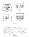
- the attached figure 1 shows some example of configurations of load heated by multiple coils.
- An induction heating system consists of a source of alternating electromagnetic flux coupled with a load, typically a ferromagnetic vessel. Eddy currents induced in the bottom of the vessel are dissipated for Joule effect, becoming heat that warms up the coil.
- the electromagnetic coupling involves mechanical vibrations of the vessel. These vibrations have the same frequency as the electromagnetic flux: actual frequency ranges adopted in induction hobs are always above the audible range, therefore there is no generation of acoustic noise for the user.
- a typical interference is the beat, i.e. an interference whose frequency is the difference between the frequencies f 1 and f 2 of the two main signals. If two waves y 1 and y 2 have slightly different frequencies, or they're not synchronized, their superposition y 1 +y 2 generates a beat with a period T beat much greater than the periods of y 1 and y 2 , as shown in figure 2 .
- the coils are powered by different power converters (with different frequency generators) the application of the same frequency is not enough: being the frequency generators independent, they are not synchronized, unless a synchronization mechanism is provided.
- a solution is known from WO-A-2007/048700 which discloses a direct link between the power converters, i.e. a cable that connects the microcontrollers of the converters, or their clock sources, or the control signals of the power transistors, and such cables send a signal from a first power converter (master) to the other (slave) that serves as a synchronization for the generation of the pulse width modulation driving signals for converters.
- An object of the present invention is to provide a new synchronization method which does not present the above problems and which is simple and reliable to be implemented.
- the present invention suggests a new method to synchronize the power converters, and hence to avoid the problem of beating.
- power converters we mean also a single power converter with two or more outputs, each of such output being connected to an induction coil.
- the present invention proposes a different approach for solving the problem of two or more coils synchronization: no direct link between the power converters or portions of a converter linked to different induction coils, but, instead, the capability of one power converter to determine the other coil drive frequency by measuring at least one electrical parameter generated by it.
- the invention proposes to synchronize the power converters by allowing a converter to measure at least one electrical parameter of a coil supplied by one reference converter, and to synchronize its output with this signal. For doing so the electrical parameter must be synchronized with the coil EM field generated that induces eddy currents in the vessel bottom.
- the start up sequence for such a system with N power converters is:
- the synchronization time i.e. the time required for each converter to measure the signal from the coil already active and to start delivering power with a synchronized frequency is sufficiently short (less than one second) so that it doesn't imply any lack of usability.
- Suitable electrical parameters of the coil to be measured for synchronization are coil voltage, coil current or any other parameters that is correlated to these ones.
- the magnetic flux generated by the induction coil current can be used.
- a sensor of the magnetic flux that is concatenated by the magnetic field concentrators usually in the form of ferrite bars, of the reference coil. Even if the use of a sensor associated to a magnetic field concentrator is preferred, nevertherless a simple coil (or several turns of conductive wire wrapped as a coil) affected by the magnetic field changes can be used as a sensor as well.
- This parameter is easy to measure also on induction coils not directly connected to the measuring power converter: it can be measured by adding a measuring coil in the form, for instance, of a conductive wire wrapped around a ferrite bar.
- Ferrite bars are preferred components due to high relative permeability [ ⁇ rel] and high electrical resistivity p and are commonly applied in a radial pattern under the induction coils for concentrating the magnetic flux.
- Ferrites are well known non-conductive ferromagnetic ceramic compounds derived from iron oxides such as hematite or magnetite as well as oxides of other metals.
- any other available sensor that transduces the flux magnetic into some electrical magnitude that uses high relative permissibility material can be used.
- other sensors based on different technology i.e. hall-effect sensor
- transducer flux magnetic into some electrical magnitude and is placed within the electromagnetic field generated by the induction coil can be used as well.
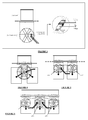
- Figure 3 shows an example of application of a ferrite bar as a magnetic flux sensor.
- the voltage v m induced on the wire is related to coil voltage: v coil ⁇ ⁇ v m hence the signal v m can be used for the synchronization of the power converters.
- FIG 7a it is shown the Vm induced on the wire wrapped around the coil.
- the zero crossing of the Vm can serve as the reference time instant for the synchronization of power transistor signal.
- the detection of zero-crossing time instant is carried out with an electrical signal conditioning circuit which is already applied in today standard control board for white-good appliance market.
- the period of the power converter that is sensed can be calculated directly considering the time intervals between consecutive Vm zero-crossing.
- Figures 4, 5 and 6 show examples of implementation of the invention with 2 and 3 power converters.
- the parameter measured for synchronization is the magnetic flux in the coil ferrite bar (i.e. the voltage v m induced on the wrapped wire).
- the change of frequency of the reference power converter can be used as an event signal for triggering specific functions for the second power converter that executes a special task (see figure 8).
- Figure 8 relates to a special function of boiling detection where an electrical parameter is sensed at a predetermined constant frequency by the reference power converter.
- the periodic change of frequency is used as a signal for the second power converter: at that point the second power converter changes the functioning mode as defined by specific function.
- the second power converter may be switched off for allowing the reference power converter to sense a less-distorted electrical parameter sensed value (in a dual Zone configuration, the magnetic cross-conduction between inner and outer coil distorts the correlation between converter electrical parameters and the pot bottom temperature)
Landscapes
- Physics & Mathematics (AREA)
- Electromagnetism (AREA)
- General Induction Heating (AREA)
- Induction Heating Cooking Devices (AREA)
Abstract
Description
- The present invention relates to a method for the synchronization of induction coils supplied by different power converters and capable of acting on a common heating zone of an induction heating system, particularly an induction cooking hob, or capable of acting on different adjacent heating zones. The present invention relates as well to an induction heating system, particularly an induction cooking hob which can carry out the above method. In the above kind of induction heating systems it is necessary to synchronize induction coils, powered by different power converters, whose generated electromagnetic (EM) fields are mutually linked due to coils proximity or due to dual zone configuration (for instance two coils concatenated: an inner coil and outer coil). This configuration is highly problematic because the interference between the coils can generate vibrations in the range of audible frequencies, highly unpleasant for the user.
- By synchronizing the coils, i.e. by synchronizing the switching of the power transistors of the power converters supplying the coils, the generation of noise during normal operation can be prevented, and the comfort of the user is guaranteed.
- The present invention relates particularly to all the configurations where the load (i.e. a metal cooking vessel) receives power from multiple induction coils, and such coils are powered by different power converters and the EM fields generated by at least two coils are mutually linked.
- The attached
figure 1 shows some example of configurations of load heated by multiple coils. - An induction heating system consists of a source of alternating electromagnetic flux coupled with a load, typically a ferromagnetic vessel. Eddy currents induced in the bottom of the vessel are dissipated for Joule effect, becoming heat that warms up the coil.
- The electromagnetic coupling involves mechanical vibrations of the vessel. These vibrations have the same frequency as the electromagnetic flux: actual frequency ranges adopted in induction hobs are always above the audible range, therefore there is no generation of acoustic noise for the user.
- If multiple sources of alternating electromagnetic flux are coupled with the same vessel, the use of frequencies above the audible range is not enough to ensure the absence of acoustic noise. If two sources are not synchronized, the superposition of the two waves on the vessel generates interference waves with different frequencies, which can fall into the audible range.
- A typical interference is the beat, i.e. an interference whose frequency is the difference between the frequencies f1 and f2 of the two main signals. If two waves y1 and y2 have slightly different frequencies, or they're not synchronized, their superposition y1+y2 generates a beat with a period Tbeat much greater than the periods of y1 and y2, as shown in
figure 2 . - For avoiding the problem, real applications must guarantee the synchronization of all the sources (coils) coupled with the same load (vessel). If such sources are powered by the same power converter the problem is quite simple: being the frequency generator (typically a microcontroller with a clock generator) the same for all the sources, it is enough that the coils are supplied at the same frequency at every time.
- If the coils are powered by different power converters (with different frequency generators) the application of the same frequency is not enough: being the frequency generators independent, they are not synchronized, unless a synchronization mechanism is provided.
- The problem of the acoustic noise due to beat generation, highly probable when multiple coils, supplied by different power converters, are coupled with the same load, is well known in the art of induction heating system, particularly for their applications to cooking appliances.
- A solution is known from
WO-A-2007/048700 which discloses a direct link between the power converters, i.e. a cable that connects the microcontrollers of the converters, or their clock sources, or the control signals of the power transistors, and such cables send a signal from a first power converter (master) to the other (slave) that serves as a synchronization for the generation of the pulse width modulation driving signals for converters. - This known solution presents some drawbacks since the connection between microcontrollers implies the use of shielded cables and it increases the overall cost of the appliance. Moreover such known solution implies also a direct electrical link between the two power converters, which can create problems of reliability and electrical insulation.
- Another solution is known from
US-A-2007/0135037 which discloses a way to operate two induction coils jointly by means of one converter circuit with two outputs, each of the output being connected to an induction coil. The converter circuit is operated in such a way that the frequency of the noise generated by the superposition of the two different switching frequencies is outside the human audibility range of frequencies. This solution makes the circuit more complex and somehow limits the possibility to change the switching frequencies of the converters in a sufficiently wide range. - An object of the present invention is to provide a new synchronization method which does not present the above problems and which is simple and reliable to be implemented.
- According to the invention, the above object is reached thanks to the features listed in the appended claims.
- The present invention suggests a new method to synchronize the power converters, and hence to avoid the problem of beating. With the term "power converters" we mean also a single power converter with two or more outputs, each of such output being connected to an induction coil. The present invention proposes a different approach for solving the problem of two or more coils synchronization: no direct link between the power converters or portions of a converter linked to different induction coils, but, instead, the capability of one power converter to determine the other coil drive frequency by measuring at least one electrical parameter generated by it.
- Further advantages and features of a method and an induction heating system according to the invention will become clear from the following detailed description, with reference to the attached drawings in which:
-
figure 1 is a typical configuration of an induction cooking hob where pan is heated by multiple induction coils, with the coils powered by different converters; -
figure 2 is showing how two signals not synchronized can generate a beat with much lower frequency; -
figure 3 is a schematic view of a preferred embodiment of the invention in which a measurement system is used for measuring indirectly the magnetic filed generated by the coil current of a first power converter; -
figure 4 is showing the embodiment offigure 3 applied to a dual concentric zone; -
figure 5 is similar tofigure 4 and shows the application to a so called "bridge" configuration in which two induction coils are adjacent and used to heat a common cooking utensil; -
figure 6 is similar tofigure 5 and show the application to a configuration in which three induction coils are adjacent to each other; -
figures 7a and 7b show how the synchronization of a second power converter is based on a zero-crossing detection circuit; and -
figure 8 shows a different use of a frequency change in the reference converter as synchronisation signal for the second converter, in a dual zone configuration. - The invention proposes to synchronize the power converters by allowing a converter to measure at least one electrical parameter of a coil supplied by one reference converter, and to synchronize its output with this signal. For doing so the electrical parameter must be synchronized with the coil EM field generated that induces eddy currents in the vessel bottom. The start up sequence for such a system with N power converters is:
- Power converter 1 (reference) starts delivering power. The other power converters are off.
- Other power converters (2-N) acquire an electrical parameter of the
coil 1 and synchronize their internal frequency generators (timers) with the signal fromcoil 1. - Once the timers are synchronized, power converters (2-N) start delivering power.
- The synchronization time, i.e. the time required for each converter to measure the signal from the coil already active and to start delivering power with a synchronized frequency is sufficiently short (less than one second) so that it doesn't imply any lack of usability.
- After that start up sequence is completed, all the power converters keep measuring the signals from the reference coil, in order to verify if their outputs are still synchronized to the reference converter: whenever a power converter not driving the reference coil detects that its output is no more synchronized with the signal from the reference coil, it synchronizes again its internal timers with the reference signal. The "re-synchronization" is carried out continuously due to the fact that the converter of the reference coil will change drive frequency for keeping the power supply constant (when power is controlled by changing frequency)
- Suitable electrical parameters of the coil to be measured for synchronization are coil voltage, coil current or any other parameters that is correlated to these ones. The magnetic flux generated by the induction coil current can be used. For sensing the magnetic flux it is preferably used a sensor of the magnetic flux that is concatenated by the magnetic field concentrators, usually in the form of ferrite bars, of the reference coil. Even if the use of a sensor associated to a magnetic field concentrator is preferred, nevertherless a simple coil (or several turns of conductive wire wrapped as a coil) affected by the magnetic field changes can be used as a sensor as well.
- This parameter is easy to measure also on induction coils not directly connected to the measuring power converter: it can be measured by adding a measuring coil in the form, for instance, of a conductive wire wrapped around a ferrite bar. Ferrite bars are preferred components due to high relative permeability [µ rel] and high electrical resistivity p and are commonly applied in a radial pattern under the induction coils for concentrating the magnetic flux. Ferrites are well known non-conductive ferromagnetic ceramic compounds derived from iron oxides such as hematite or magnetite as well as oxides of other metals. However, any other available sensor that transduces the flux magnetic into some electrical magnitude that uses high relative permissibility material can be used. Moreover, other sensors based on different technology (i.e. hall-effect sensor) that transducer flux magnetic into some electrical magnitude and is placed within the electromagnetic field generated by the induction coil can be used as well.
-
Figure 3 shows an example of application of a ferrite bar as a magnetic flux sensor. - The voltage vm induced on the wire wrapped around the ferrite is proportional to the variation of the magnetic field, according to Faraday's law (where N is the number of turns of wire and ΦB is the magnetic flux):

- The magnetic flux that is linked to the wire wrapped around the ferrite is generated by the coil current:

where M is the mutual inductance between the induction coil and the magnetic flux. - As the coil voltage and the voltage vm induced on the wire depends on the derivate of the induction coil current:


- Therefore the voltage vm induced on the wire is related to coil voltage:

hence the signal vm can be used for the synchronization of the power converters. - For instance, in
figure 7a it is shown the Vm induced on the wire wrapped around the coil. The zero crossing of the Vm can serve as the reference time instant for the synchronization of power transistor signal. The detection of zero-crossing time instant is carried out with an electrical signal conditioning circuit which is already applied in today standard control board for white-good appliance market. - Thus, the period of the power converter that is sensed can be calculated directly considering the time intervals between consecutive Vm zero-crossing.
-
Figures 4, 5 and 6 show examples of implementation of the invention with 2 and 3 power converters. The parameter measured for synchronization is the magnetic flux in the coil ferrite bar (i.e. the voltage vm induced on the wrapped wire). Infigures 4 and 5 the two power converters start-up sequence is as follows:
Reference =coil 1 -
Power converter 2 acquires a synchronization signal fromcoil 1 -
Power converter 2 synchronizes its timers with the signal -
Power converter 2 starts delivering power with same frequency that usesconverter 1. - In
figure 6 the three power converters start-up sequence is as follows:
Reference =coil 2 - •
Power converters coil 2 - •
Power converters - •
Power converter converter 1. - It is important to notice that by using the magnetic flux induced in a coil ferrite bar as reference electrical parameter, no electrical connection between power converters is required and they are electrically isolated.
- Moreover, the change of frequency of the reference power converter can be used as an event signal for triggering specific functions for the second power converter that executes a special task (see
figure 8). Figure 8 relates to a special function of boiling detection where an electrical parameter is sensed at a predetermined constant frequency by the reference power converter. The periodic change of frequency is used as a signal for the second power converter: at that point the second power converter changes the functioning mode as defined by specific function. For instance, in case of dual zone coil topologies, once it detects a fixed change of frequency of the reference power converter, the second power converter may be switched off for allowing the reference power converter to sense a less-distorted electrical parameter sensed value (in a dual Zone configuration, the magnetic cross-conduction between inner and outer coil distorts the correlation between converter electrical parameters and the pot bottom temperature) - Furthermore, other different type of information/message between converters can be implemented by using the change of frequency and the intervals between such changes as way of representing bits as today standard protocols of communication.
Claims (11)
- Method for the synchronization of induction coils supplied by power converters and acting on a common heating zone or on adjacent heating zones of an induction heating system, particularly of an induction cooking hob, characterized in that it comprises the steps of activating a first power converter, detecting a parameter correlated to the magnetic field generated by said first power converter and activating a second power converter by using said parameter as synchronization signal.
- Method according to claim 1, wherein said parameter is induction coil voltage or induction coil current or a combination thereof.
- Method according to claim 1, wherein said parameter is measured on a sensing circuit.
- Method according to claim 3, wherein the sensing circuit is associated to a magnetic field concentrator of the induction coil.
- Method according to claim 3, wherein said parameter is the voltage Vm induced on the sensing circuit formed as a wire wrapped around a magnetic field concentrator, according to Faraday's law:

where N is the number of turns of the wire, and ΦB is the magnetic flux. - Method according to claim 5, wherein a zero crossing of the voltage (Vm) induced on the sensing circuit is used as the reference for the synchronization signal.
- Induction heating system, particularly for cooking appliances, comprising induction coils supplied by power converters and capable of defining a common heating zone or adjacent heating zones, characterized in that it comprises detecting means for detecting a parameter correlated to the magnetic field generated by a first power converter and synchronization means for delivering such parameter as a synchronization signal to a second power converter.
- Induction heating system according to claim 7, wherein said parameter is induction coil voltage or induction coil current or a combination thereof.
- Induction heating system according to claim 7, comprising magnetic field concentrators associated to the induction coils, wherein said detecting means comprises at least one sensing circuit associated to one magnetic field concentrator.
- Induction heating system according to claim 9, wherein each sensing circuit comprises a wire wrapped around a magnetic field concentrator.
- Induction heating system according to claim 10, wherein the magnetic field concentrators are ferrite bars disposed in a radial pattern and facing the induction coils.
Priority Applications (4)
| Application Number | Priority Date | Filing Date | Title |
|---|---|---|---|
| EP09150702.0A EP2209350B1 (en) | 2009-01-16 | 2009-01-16 | Method for the synchronization of induction coils supplied by power converters of an induction cooking hob and induction heating system carrying out such method |
| CA2689770A CA2689770C (en) | 2009-01-16 | 2010-01-06 | Method for the synchronization of induction coils supplied by power converters of an induction cooking hob and induction heating system carrying out such method |
| BRPI1006332A BRPI1006332B1 (en) | 2009-01-16 | 2010-01-13 | method for synchronization of induction coils fed by energy converters of an induction cooking hob and induction heating system which performs such method |
| US12/687,307 US8431875B2 (en) | 2009-01-16 | 2010-01-14 | Method for the synchronization of induction coils supplied by power converters of an induction cooking hob and induction heating system carrying out such method |
Applications Claiming Priority (1)
| Application Number | Priority Date | Filing Date | Title |
|---|---|---|---|
| EP09150702.0A EP2209350B1 (en) | 2009-01-16 | 2009-01-16 | Method for the synchronization of induction coils supplied by power converters of an induction cooking hob and induction heating system carrying out such method |
Publications (2)
| Publication Number | Publication Date |
|---|---|
| EP2209350A1 true EP2209350A1 (en) | 2010-07-21 |
| EP2209350B1 EP2209350B1 (en) | 2018-11-28 |
Family
ID=40908526
Family Applications (1)
| Application Number | Title | Priority Date | Filing Date |
|---|---|---|---|
| EP09150702.0A Active EP2209350B1 (en) | 2009-01-16 | 2009-01-16 | Method for the synchronization of induction coils supplied by power converters of an induction cooking hob and induction heating system carrying out such method |
Country Status (4)
| Country | Link |
|---|---|
| US (1) | US8431875B2 (en) |
| EP (1) | EP2209350B1 (en) |
| BR (1) | BRPI1006332B1 (en) |
| CA (1) | CA2689770C (en) |
Cited By (2)
| Publication number | Priority date | Publication date | Assignee | Title |
|---|---|---|---|---|
| EP3462813A1 (en) * | 2017-09-29 | 2019-04-03 | LG Electronics Inc. -1- | Induction heating and wireles power transferring device having improved target object detection algorithm |
| EP3641494A1 (en) * | 2018-10-17 | 2020-04-22 | BSH Hausgeräte GmbH | Cooking device |
Families Citing this family (8)
| Publication number | Priority date | Publication date | Assignee | Title |
|---|---|---|---|---|
| EP2065648B1 (en) * | 2007-11-28 | 2016-03-09 | Electrolux Home Products Corporation N.V. | A method and an apparatus for controlling a cooking device, in particular an induction hob |
| ITTO20120896A1 (en) | 2012-10-15 | 2014-04-16 | Indesit Co Spa | INDUCTION HOB |
| US10605464B2 (en) | 2012-10-15 | 2020-03-31 | Whirlpool Corporation | Induction cooktop |
| EP3432682B1 (en) | 2017-07-18 | 2026-04-08 | Whirlpool Corporation | Method for operating an induction cooking hob and cooking hob using such method |
| US10993292B2 (en) | 2017-10-23 | 2021-04-27 | Whirlpool Corporation | System and method for tuning an induction circuit |
| US11140751B2 (en) | 2018-04-23 | 2021-10-05 | Whirlpool Corporation | System and method for controlling quasi-resonant induction heating devices |
| US12588112B2 (en) | 2018-04-23 | 2026-03-24 | Whirlpool Corporation | System and method for controlling induction heating devices with series connected switching devices |
| US12302478B2 (en) | 2018-04-23 | 2025-05-13 | Whirlpool Corporation | Control circuits and methods for distributed induction heating devices |
Citations (3)
| Publication number | Priority date | Publication date | Assignee | Title |
|---|---|---|---|---|
| WO2004004420A1 (en) * | 2002-06-26 | 2004-01-08 | Mitsui Engineering & Shipbuilding Co.,Ltd. | Induction heating method and unit |
| WO2007048700A1 (en) | 2005-10-27 | 2007-05-03 | BSH Bosch und Siemens Hausgeräte GmbH | Cooking hob and method for the operation of a cooking hob |
| US20070135037A1 (en) | 2003-11-03 | 2007-06-14 | Barragan Perez Luis A | Method for operating a frequency converter circuit |
Family Cites Families (3)
| Publication number | Priority date | Publication date | Assignee | Title |
|---|---|---|---|---|
| CN100508671C (en) * | 2002-03-12 | 2009-07-01 | 松下电器产业株式会社 | induction heating device |
| GB0208572D0 (en) * | 2002-04-13 | 2002-05-22 | Koninkl Philips Electronics Nv | X-ray diffraction apparatus and method |
| JP2005028594A (en) * | 2003-07-07 | 2005-02-03 | Ricoh Co Ltd | Image forming apparatus |
-
2009
- 2009-01-16 EP EP09150702.0A patent/EP2209350B1/en active Active
-
2010
- 2010-01-06 CA CA2689770A patent/CA2689770C/en active Active
- 2010-01-13 BR BRPI1006332A patent/BRPI1006332B1/en active IP Right Grant
- 2010-01-14 US US12/687,307 patent/US8431875B2/en active Active
Patent Citations (3)
| Publication number | Priority date | Publication date | Assignee | Title |
|---|---|---|---|---|
| WO2004004420A1 (en) * | 2002-06-26 | 2004-01-08 | Mitsui Engineering & Shipbuilding Co.,Ltd. | Induction heating method and unit |
| US20070135037A1 (en) | 2003-11-03 | 2007-06-14 | Barragan Perez Luis A | Method for operating a frequency converter circuit |
| WO2007048700A1 (en) | 2005-10-27 | 2007-05-03 | BSH Bosch und Siemens Hausgeräte GmbH | Cooking hob and method for the operation of a cooking hob |
Cited By (3)
| Publication number | Priority date | Publication date | Assignee | Title |
|---|---|---|---|---|
| EP3462813A1 (en) * | 2017-09-29 | 2019-04-03 | LG Electronics Inc. -1- | Induction heating and wireles power transferring device having improved target object detection algorithm |
| US11533787B2 (en) | 2017-09-29 | 2022-12-20 | Lg Electronics Inc. | Induction heating and wireless power transferring device having improved target object detection algorithm |
| EP3641494A1 (en) * | 2018-10-17 | 2020-04-22 | BSH Hausgeräte GmbH | Cooking device |
Also Published As
| Publication number | Publication date |
|---|---|
| BRPI1006332B1 (en) | 2019-12-24 |
| BRPI1006332A2 (en) | 2012-11-06 |
| US20100181301A1 (en) | 2010-07-22 |
| CA2689770C (en) | 2017-04-25 |
| CA2689770A1 (en) | 2010-07-16 |
| US8431875B2 (en) | 2013-04-30 |
| EP2209350B1 (en) | 2018-11-28 |
Similar Documents
| Publication | Publication Date | Title |
|---|---|---|
| EP2209350B1 (en) | Method for the synchronization of induction coils supplied by power converters of an induction cooking hob and induction heating system carrying out such method | |
| EP2034801B1 (en) | An improved induction cooking appliance and a method for checking the cooking capabilities of a piece of cookware | |
| JP7550856B2 (en) | Foreign object detection in wireless power transmission systems | |
| EP2209351A1 (en) | A method for detecting the pan size in induction cooking hobs and induction cooking hob for carrying out such method | |
| JP5586433B2 (en) | Method and induction heating apparatus for determining the temperature of a cooking vessel base heated by an induction heating coil | |
| JP4850220B2 (en) | Induction heating cooker | |
| EP3481147B1 (en) | Induction heating device and method for determining loaded-object on the induction heating device | |
| EP3700058B1 (en) | Inductive power transmitter | |
| JP5474213B2 (en) | Induction heating cooker and control method thereof | |
| JP6038345B2 (en) | Induction heating cooker | |
| WO2009037783A1 (en) | Cooling apparatus for electromagnetic induction heating cooker | |
| EP2095022B1 (en) | Cooking apparatus | |
| EP2209352B1 (en) | Induction cooking heater and method for the control thereof | |
| US7126095B2 (en) | Frying hob arrangement with induction heating | |
| US6737617B1 (en) | Methods and apparatus for a signal distortion based detection system | |
| JP5142856B2 (en) | Induction heating cooker | |
| CN108141923A (en) | Induction heating method and system | |
| CN114060873B (en) | Pot support, control method thereof and kitchen range | |
| CN110572893B (en) | Electromagnetic heating device and temperature control method | |
| JP2005166391A (en) | Induction heating cooker | |
| KR102321975B1 (en) | Detachable cookware and its control method | |
| EP4518581A1 (en) | Induction cooking and powering cooking appliances | |
| TW202232855A (en) | Foreign object detection in a wireless power transfer system | |
| JPS61195584A (en) | Temperature controller for induction heating cooker | |
| JP2005235486A (en) | Induction heating apparatus and induction heating cooker provided with the same |
Legal Events
| Date | Code | Title | Description |
|---|---|---|---|
| PUAI | Public reference made under article 153(3) epc to a published international application that has entered the european phase |
Free format text: ORIGINAL CODE: 0009012 |
|
| AK | Designated contracting states |
Kind code of ref document: A1 Designated state(s): AT BE BG CH CY CZ DE DK EE ES FI FR GB GR HR HU IE IS IT LI LT LU LV MC MK MT NL NO PL PT RO SE SI SK TR |
|
| AX | Request for extension of the european patent |
Extension state: AL BA RS |
|
| 17P | Request for examination filed |
Effective date: 20110117 |
|
| AKX | Designation fees paid |
Designated state(s): DE ES FR GB IT PL |
|
| 17Q | First examination report despatched |
Effective date: 20110318 |
|
| GRAP | Despatch of communication of intention to grant a patent |
Free format text: ORIGINAL CODE: EPIDOSNIGR1 |
|
| STAA | Information on the status of an ep patent application or granted ep patent |
Free format text: STATUS: GRANT OF PATENT IS INTENDED |
|
| INTG | Intention to grant announced |
Effective date: 20180912 |
|
| GRAS | Grant fee paid |
Free format text: ORIGINAL CODE: EPIDOSNIGR3 |
|
| GRAA | (expected) grant |
Free format text: ORIGINAL CODE: 0009210 |
|
| STAA | Information on the status of an ep patent application or granted ep patent |
Free format text: STATUS: THE PATENT HAS BEEN GRANTED |
|
| AK | Designated contracting states |
Kind code of ref document: B1 Designated state(s): DE ES FR GB IT PL |
|
| REG | Reference to a national code |
Ref country code: GB Ref legal event code: FG4D |
|
| REG | Reference to a national code |
Ref country code: DE Ref legal event code: R096 Ref document number: 602009055869 Country of ref document: DE |
|
| PG25 | Lapsed in a contracting state [announced via postgrant information from national office to epo] |
Ref country code: ES Free format text: LAPSE BECAUSE OF FAILURE TO SUBMIT A TRANSLATION OF THE DESCRIPTION OR TO PAY THE FEE WITHIN THE PRESCRIBED TIME-LIMIT Effective date: 20181128 |
|
| PG25 | Lapsed in a contracting state [announced via postgrant information from national office to epo] |
Ref country code: PL Free format text: LAPSE BECAUSE OF FAILURE TO SUBMIT A TRANSLATION OF THE DESCRIPTION OR TO PAY THE FEE WITHIN THE PRESCRIBED TIME-LIMIT Effective date: 20181128 |
|
| REG | Reference to a national code |
Ref country code: DE Ref legal event code: R097 Ref document number: 602009055869 Country of ref document: DE |
|
| PLBE | No opposition filed within time limit |
Free format text: ORIGINAL CODE: 0009261 |
|
| STAA | Information on the status of an ep patent application or granted ep patent |
Free format text: STATUS: NO OPPOSITION FILED WITHIN TIME LIMIT |
|
| 26N | No opposition filed |
Effective date: 20190829 |
|
| P01 | Opt-out of the competence of the unified patent court (upc) registered |
Effective date: 20230522 |
|
| PGFP | Annual fee paid to national office [announced via postgrant information from national office to epo] |
Ref country code: FR Payment date: 20250127 Year of fee payment: 17 |
|
| PGFP | Annual fee paid to national office [announced via postgrant information from national office to epo] |
Ref country code: IT Payment date: 20250122 Year of fee payment: 17 |
|
| PGFP | Annual fee paid to national office [announced via postgrant information from national office to epo] |
Ref country code: GB Payment date: 20260126 Year of fee payment: 18 |
|
| PGFP | Annual fee paid to national office [announced via postgrant information from national office to epo] |
Ref country code: DE Payment date: 20260127 Year of fee payment: 18 |