EP2209241B1 - System and method for a cross channel data link (CCDL) - Google Patents
System and method for a cross channel data link (CCDL) Download PDFInfo
- Publication number
- EP2209241B1 EP2209241B1 EP10150390.2A EP10150390A EP2209241B1 EP 2209241 B1 EP2209241 B1 EP 2209241B1 EP 10150390 A EP10150390 A EP 10150390A EP 2209241 B1 EP2209241 B1 EP 2209241B1
- Authority
- EP
- European Patent Office
- Prior art keywords
- time
- triggered
- control nodes
- data
- tte
- Prior art date
- Legal status (The legal status is an assumption and is not a legal conclusion. Google has not performed a legal analysis and makes no representation as to the accuracy of the status listed.)
- Not-in-force
Links
Images


Classifications
-
- G—PHYSICS
- G06—COMPUTING OR CALCULATING; COUNTING
- G06F—ELECTRIC DIGITAL DATA PROCESSING
- G06F1/00—Details not covered by groups G06F3/00 - G06F13/00 and G06F21/00
- G06F1/04—Generating or distributing clock signals or signals derived directly therefrom
- G06F1/14—Time supervision arrangements, e.g. real time clock
-
- G—PHYSICS
- G05—CONTROLLING; REGULATING
- G05D—SYSTEMS FOR CONTROLLING OR REGULATING NON-ELECTRIC VARIABLES
- G05D1/00—Control of position, course, altitude or attitude of land, water, air or space vehicles, e.g. using automatic pilots
- G05D1/0055—Control of position, course, altitude or attitude of land, water, air or space vehicles, e.g. using automatic pilots with safety arrangements
- G05D1/0077—Control of position, course, altitude or attitude of land, water, air or space vehicles, e.g. using automatic pilots with safety arrangements using redundant signals or controls
-
- H—ELECTRICITY
- H04—ELECTRIC COMMUNICATION TECHNIQUE
- H04W—WIRELESS COMMUNICATION NETWORKS
- H04W84/00—Network topologies
- H04W84/18—Self-organising networks, e.g. ad-hoc networks or sensor networks
-
- G—PHYSICS
- G06—COMPUTING OR CALCULATING; COUNTING
- G06F—ELECTRIC DIGITAL DATA PROCESSING
- G06F11/00—Error detection; Error correction; Monitoring
- G06F11/07—Responding to the occurrence of a fault, e.g. fault tolerance
- G06F11/16—Error detection or correction of the data by redundancy in hardware
- G06F11/18—Error detection or correction of the data by redundancy in hardware using passive fault-masking of the redundant circuits
- G06F11/182—Error detection or correction of the data by redundancy in hardware using passive fault-masking of the redundant circuits based on mutual exchange of the output between redundant processing components
-
- H—ELECTRICITY
- H04—ELECTRIC COMMUNICATION TECHNIQUE
- H04L—TRANSMISSION OF DIGITAL INFORMATION, e.g. TELEGRAPHIC COMMUNICATION
- H04L12/00—Data switching networks
- H04L12/28—Data switching networks characterised by path configuration, e.g. LAN [Local Area Networks] or WAN [Wide Area Networks]
- H04L12/40—Bus networks
- H04L2012/40267—Bus for use in transportation systems
- H04L2012/40273—Bus for use in transportation systems the transportation system being a vehicle
Definitions
- Critical systems often require high levels of fault tolerance. For example, flight computers in aircraft (which are responsible for controlling certain operations of an aircraft during flight) are required to be fault tolerant. If a fault does occur in a fault-tolerant critical system, the system will continue to operate properly due to the fault tolerance. In order to achieve the required levels of fault tolerance, many systems incorporate redundancy into the network. For example, in some systems multiple redundant flight computers are used so that if one flight computer fails, the other redundant flight computers are able to continue controlling operation of the aircraft.
- CCDL cross channel data links
- the CCDL enables each redundant computer to transmit to and receive messages from each of the other redundant computers.
- the CCDL can be used to ensure that bad data from elsewhere in the system does not propagate and become the majority input to the redundant computers.
- the use of a CCDL includes multiple exchanges of data between the redundant computers, comparison and voting of input data, and selection of a majority opinion.
- the CCDL is used to synchronize the time base between the redundant computers so that each redundant computer is executing the same application task substantially simultaneously.
- WO2008/124854 discloses a method to improve user data efficiency and security in a distributed real-time computer system, in which a number of node computers communicate by means of TT Ethernet messages via one or more communications channels, using commercially available Ethernet controllers.
- WO03/107609 discloses a communication method for transmitting Ethernet messages in a distributed real-time system in which a plurality of network node computers, e.g. four network node computers comprising at least one communication controller each, are linked via a communication system that comprises one or more communication channels, whereby in every communication channel one or more intelligent star couplers are disposed.
- WO93/11481 discloses a method to operate computer units that communicate with each other by serial data exchange over a data bus, each computer unit having its own clock generator system and the computer units exchange clock information over the data bus.
- a node comprises a host computer operable to execute application tasks and to transmit data; a local time-triggered Ethernet switch operable to enforce temporal constraints on time-triggered data; and a time-triggered Ethernet controller coupled to the local time-triggered Ethernet switch and operable to be coupled to a time triggered Ethernet switch in each of a plurality of other control nodes.
- the time-triggered Ethernet controller is further operable to communicate with the plurality of other control nodes to synchronize a local clock to establish a global time base and to provide a signal to the host computer for the host computer to synchronize execution of the application tasks by the host computer with the execution of application tasks in each of the plurality of other control nodes, receive a copy of data via each of the local time-triggered Ethernet switch (108) and the time-triggered Ethernet switch in each of the plurality of other control nodes and to select one of the plurality of received copies of data to present to the host computer (112), and operable to select a received copy that has passed an error detection algorithm and is determined to be valid for the time-triggered Ethernet controller (110).
- FIG. 1 is a block diagram of a network 100.
- Network 100 includes a plurality of control nodes 102-1 ... 102-N, a plurality of sensors 104-1 ... 104-M, and a plurality of actuators 106-1 ... 106-X.
- Network 100 can be implemented, for example, in or as a critical system, such as an aircraft flight system or automotive system.
- network 100 is implemented in an aircraft flight system and control nodes 102-1 ... 102-N are redundant flight computers.
- an aircraft flight system is described in this exemplary embodiment, it is to be understood that in other embodiments, the techniques described here can be implemented in other systems, such as spacecraft, automotive, or other network systems.
- 102-N is communicatively coupled to each of sensors 104-1 ... 104-M.
- Sensors 104-1 ... 104-M communicate data to each of control nodes 102-1 ... 102-N, such as, but not limited to, aircraft heading, thrust, pitch, user input, etc.
- Each of the control nodes 102-1 ... 102-N are redundant. That is, each of the redundant control nodes 102-1 ... 102-N, in the absence of any faults, should be in the same state at the application layer.
- Each of control nodes 102-1 ... 102-N processes the data received from sensors 104-1 ... 104-M.
- control nodes 102-1 ... 102-N communicate with each other to prevent faulty data from propagating and becoming the majority as described in more detail below with respect to FIG. 2 .
- Control nodes 102-1 ... 102-N also transmit control signals based on the processed sensor data to actuators 106-1 ... 106-X to control operation of the aircraft.
- actuators 106-1 ... 106-X can include, but are not limited to, wing flaps, engine thrust, etc.
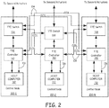
- FIG. 2 is a more detailed block diagram of control nodes 102-1 ... 102-N and the connections between them.
- each control node 102 comprises a time triggered Ethernet (TTE) switch 108, a time-triggered Ethernet (TTE) controller 110, and a host computer 112.
- switch 108 is a gigabit time-triggered Ethernet switch and controller 110 is a time-triggered gigabit Ethernet controller.
- TTE controller 110 and TTE switch 108 are implemented as application specific integrated circuits (ASIC).
- ASIC application specific integrated circuits
- the TTe controller 110 and the TTE switch 108 are implemented in other ways (for example, using a field programmable gate array (FPGA)).
- FPGA field programmable gate array
- Time-triggered Ethernet is a communication architecture that supports both event triggered and time-triggered traffic.
- Typical Ethernet systems based on the IEEE 802.3 standard support only event-triggered traffic. That is, such event-triggered systems initiate an action, such as sending a message or executing a task, based on the occurrence of a non-temporal event.
- Time-triggered systems initiate actions based on reaching a predetermined moment in a global time base. Additional details regarding time-triggered Ethernet can be found in H.
- TTE Papers Each of the TTE Papers is hereby incorporated herein by reference.
- a time-triggered Ethernet switch 108 can process both time-triggered and event-triggered traffic. For example, if both a time-triggered message and an event-triggered message are received at switch 108, switch 108 will forward the time-triggered message with a constant a priori known delay according to the timed transmission schedule. Time-triggered Ethernet switch 108 buffers the event-triggered message until it can be transmitted when no other time triggered messages are being transmitted. Time-Triggered Ethernet switch 108 also enforces temporal constraints on time-triggered messages. For example, if a time-triggered message is received outside a valid receive window according to the transmission schedule, time-triggered Ethernet switch 108 discards the message.
- CCDL 114 are implemented as copper wires in this embodiment. However, it is to be understood that in other embodiments, other suitable media for communicating time-triggered Ethernet signals can be implemented, such as fiber optic cable.
- Time-triggered Ethernet controller 110 buffers messages to be transmitted from the host computer 112 in order to transmit the messages according to the transmission schedule.
- Time triggered Ethernet controller 110 in each control node 102 is also operable to synchronize the execution of application tasks on the respective host computer with the other host computers 112 using the global time base established by the TTE controller 110 for communications over the CCDL 114.
- application task refers to a task executed by the host computer related to the primary function of the host computer. For example, application tasks for an aircraft flight computer are tasks related to the flying of the aircraft.
- each TTE controller 110 is coupled to the respective TTE switch 108 in each of control nodes 102-1 ... 102-N via the plurality of CCDL links 114.
- each TTE controller 110 is coupled to the other TTE controllers 110 via three independent paths.
- the TTE controllers 110 in each control node 102 communicate with each other over the three independent paths to synchronize their respective local clocks to a global time base.
- a global time base is established by the TTE controllers 110 and TTE switches 108 using the distributed clock synchronization mechanism described in the TTE Papers.
- a master clock is not used. Due to the redundant CCDL paths 114, each TTE controller 110 can synchronize its local clock to the global time base even if its local TTE switch 108 has failed.
- the host computers 112 synchronize the execution of the application tasks.
- the host computers themselves must implement a clock synchronization mechanism to synchronize their local clocks such that host computers are executing application tasks substantially simultaneously. Typically, this is done by having the host computers exchange special messages that are used for such synchronization.
- the TTE controllers 110 included in each control node 102 already implement a clock synchronization mechanism that is used to synchronize the local clocks used by the TTE controllers 110 and the TTE switches 108 and establish a global time base for the purposes of communicating over the CCDL links 114.
- this global time base that is established by the TTE controllers 110 and TTE switches 108 for communicating over the CCDL links 114 is also used to synchronize the execution of the applications tasks by the host computers 112.
- the host computers 112 need not implement a separate clock synchronization mechanism to establish a separate global time base for synchronizing the local clocks used by each of the host computers 112 in executing the application tasks.
- the global time base that is established by the TTE controllers 110 and TTE switches 108 for the purpose of communicating over the CCDL links 114 is also used by the host computers 112 as the global time base for synchronizing the execution of the application tasks.
- each TTE controller 110 then provides a synchronization signal to its respective host computer 112 to synchronize the execution of application tasks. For example, in one implementation of this embodiment, each TTE controller 110 periodically asserts an interrupt signal 116 based on the global time base established by the TTE controllers 110 and TTE switches 108 for the purpose of communicating over the CCDL links 114. Each host computer 112 uses the interrupt signal 116 to schedule the execution of the application tasks.
- the TTE controllers 110 are synchronized to their global time base and use this global time base to generate the interrupt signal 116, the execution of application tasks by each host computer 112 is also synchronized to that global time base. By synchronizing the execution of the application tasks by the host computers 112 in this way, less processing demand is placed on host computers 112, which frees more processing power to be used for important application tasks.
- network 100 moves some fault detection functionality from host computers 112 to TTE controllers 110.
- the host computers exchange data multiple times to identify and isolate faulty data.
- the host computers each receive three copies of data that is transmitted. Each host computer then compares the three copies to identify faults in the three copies. The host computers then exchange data again to communicate each host computers view of the message copies to guarantee fault tolerance.
- the exchange of data is simplified and the isolation of faults is performed in the TTE switches 108 and TTE controllers 110.
- switch 108 transmits a copy of that data to the TTE controller 110 in each of the control nodes 102 via the corresponding CCDL links 114.
- each TTE controller 110 forwards copies of that data to the other control nodes 102 on each CCDL link 114.
- Each TTE switch 108 enforces temporal constraints on the received copies of data to discard data which is transmitted out of the corresponding window for that time slot.
- each of the redundant control nodes 102 there are three redundant control nodes 102. That is, each of the redundant control nodes 102, in the absence of any faults, should be in the same state at the application layer.
- the TTE communication processing performed by the TTE controllers 110 in each of the control nodes 102 presents to the respective host computer 112 in the control node 102 only a single copy of each data message that is transmitted in the network 100, even though multiple copies of each such data message are received at the respective TTE controller 110.
- Each TTE controller 110 is responsible for selecting the proper (that is, valid) copy of each such data message presented to the host computer 112.
- each TTE controller 110 receives three copies of the data message -- one that is forwarded directly to it from its respective TTE switch 108 and two others that are forwarded from the TTE switches 108 of the other two control nodes 102.
- Each TTE controller 110 performs an error detection algorithm, such as a cyclic redundancy check (CRC) on the received copies of the data message.
- CRC cyclic redundancy check
- Each TTE controller 110 also verifies that the messages are valid. For example, each TTE controller 110 determines if it is valid for the source of the data message to have addressed it to the particular destination specified in the message (for example, based on the transmission schedule).
- each TTE controller 110 does not compare the data copies. Rather, each TTE controller 110 selects one of the three copies that passes an error detection algorithm and is a valid message. If only one copy is valid and passes the error detection algorithm, only that copy is selected. If more than one of the copies is valid and passes the error detection algorithm, each TTE controller 110 selects only one copy based on an a priori scheme. For example, in some embodiments, a default order of the CCDL links 114 is used to select the copy. Each TTE controller 110 then forwards only the selected copy of the data to the respective host computer 112. Thus, the host computer 112 need not analyze and compare multiple copies of data to identify faults, which further reduces the processing burden on host computer 112. Thus, by leveraging the TTE architecture, network 100 is able to move synchronization and fault isolation functionality from the host computer 112 to the TTE controller 110 and TTE switch 108, which frees more processing power for application tasks executed by the host computer 112.
- FIG. 3 is a flow chart depicting one embodiment of a method 300 of communicating in a network.
- Method 300 is described here as being implemented in network 100 of FIG. 1 and 2 .
- a TTE controller 110 in each of a plurality of control nodes periodically communicates with the TTE controllers 110 in the other control nodes and the TTE switches 108 to synchronize their local clocks and establish a global time base.
- each TTE controller 110 transmits a synchronization signal to a respective host computer 112 in the respective control node 102 in order to synchronize the execution of application tasks by the plurality of host computers 112.
- the synchronization signal establishes the time base for the host computer 112.
- the synchronization signal is an interrupt signal.
- a copy of a message is received at a TTE switch 108 in each of the plurality of control nodes 102.
- each TTE switch 108 enforces temporal constraints on the received message using the global time base.
- the received message can be data received from any component coupled to the TTE switch 108, such as a TTE controller 110 in one of the control nodes 102, a sensor 104, or an actuator 106.
- each TTE switch 108 provides a copy of the received message to a TTE controller 110 in each of the control nodes 102 via a plurality of cross channel data links 114.
- each TTE controller 110 receives a plurality of copies of the message.
- each TTE controller 110 selects one of the plurality of received copies of the message. In particular, each TTE controller 110 performs an error detection algorithm on each copy and verifies that each copy of the message is valid. Each TTE controller 110 then selects a message copy which passes the error detection algorithm (a healthy copy) and is valid. If more than one copy is healthy and valid, each TTE controller 110 selects one of the copies based on a pre-determined scheme. At 314, each TTE controller 110 forwards only the selected copy of the message to a host computer 112 in the respective control node 102 for processing.
- TTE controller 110, TTE switch and/or host computer 112 can be implemented using software, firmware, hardware, or any appropriate combination thereof, as known to one of skill in the art.
- these hardware components can include one or more microprocessors, memory elements, digital signal processing elements, look-up tables, interface cards, and other standard components known in the art. Any of the foregoing may be supplemented by, or incorporated in, specially-designed application-specific integrated circuits (ASIC) and field programmable gate arrays (FPGA).
- ASIC application-specific integrated circuits
- FPGA field programmable gate arrays
- TTE controller 110 includes or functions with software programs, firmware or computer readable instructions for carrying out various methods, process tasks, calculations, and control functions, used in the processing functions described above, such as synchronization of local clocks to a global time base.
- These instructions are typically tangibly embodied on any appropriate medium used for storage of computer readable instructions or data structures.
- Suitable processor-readable media may include storage or memory media such as magnetic or optical media.
- storage or memory media may include conventional hard disks, Compact Disk - Read Only Memory (CD-ROM), volatile or non-volatile media such as Random Access Memory (RAM) (including, but not limited to, Synchronous Dynamic Random Access Memory (SDRAM), Double Data Rate (DDR) RAM, RAMBUS Dynamic RAM (RDRAM), Static RAM (SRAM), etc.), Read Only Memory (ROM), Electrically Erasable Programmable ROM (EEPROM), and flash memory, etc.
- Suitable processor-readable media may also include transmission media such as electrical, electromagnetic, or digital signals, conveyed via a communication medium such as a network and/or a wireless link.
Landscapes
- Engineering & Computer Science (AREA)
- Theoretical Computer Science (AREA)
- Physics & Mathematics (AREA)
- General Physics & Mathematics (AREA)
- Signal Processing (AREA)
- General Engineering & Computer Science (AREA)
- Computer Networks & Wireless Communication (AREA)
- Aviation & Aerospace Engineering (AREA)
- Radar, Positioning & Navigation (AREA)
- Remote Sensing (AREA)
- Automation & Control Theory (AREA)
- Small-Scale Networks (AREA)
- Computer And Data Communications (AREA)
- Hardware Redundancy (AREA)
Description
- Critical systems often require high levels of fault tolerance. For example, flight computers in aircraft (which are responsible for controlling certain operations of an aircraft during flight) are required to be fault tolerant. If a fault does occur in a fault-tolerant critical system, the system will continue to operate properly due to the fault tolerance. In order to achieve the required levels of fault tolerance, many systems incorporate redundancy into the network. For example, in some systems multiple redundant flight computers are used so that if one flight computer fails, the other redundant flight computers are able to continue controlling operation of the aircraft.
- It is often necessary for the redundant computers to communicate so that at least a majority of the redundant computers agree on the output sent to other system components. Communication between the redundant flight computers is achieved through cross channel data links (CCDL) in some systems. The CCDL enables each redundant computer to transmit to and receive messages from each of the other redundant computers. In this way, the CCDL can be used to ensure that bad data from elsewhere in the system does not propagate and become the majority input to the redundant computers. Thus, the use of a CCDL includes multiple exchanges of data between the redundant computers, comparison and voting of input data, and selection of a majority opinion. In addition, the CCDL is used to synchronize the time base between the redundant computers so that each redundant computer is executing the same application task substantially simultaneously.
-
WO2008/124854 discloses a method to improve user data efficiency and security in a distributed real-time computer system, in which a number of node computers communicate by means of TT Ethernet messages via one or more communications channels, using commercially available Ethernet controllers.WO03/107609 WO93/11481 - Although, the multiple exchanges of data and synchronization of time base enable the redundant computers to achieve the necessary fault tolerance, the fault tolerance comes at the expense of computer performance. Each of the redundant computers has to process all the exchanged data, which places an additional burden on the redundant computers.
- The invention is set out as described in the claims. In one embodiment, a node is provided. The node comprises a host computer operable to execute application tasks and to transmit data; a local time-triggered Ethernet switch operable to enforce temporal constraints on time-triggered data; and a time-triggered Ethernet controller coupled to the local time-triggered Ethernet switch and operable to be coupled to a time triggered Ethernet switch in each of a plurality of other control nodes. The time-triggered Ethernet controller is further operable to communicate with the plurality of other control nodes to synchronize a local clock to establish a global time base and to provide a signal to the host computer for the host computer to synchronize execution of the application tasks by the host computer with the execution of application tasks in each of the plurality of other control nodes, receive a copy of data via each of the local time-triggered Ethernet switch (108) and the time-triggered Ethernet switch in each of the plurality of other control nodes and to select one of the plurality of received copies of data to present to the host computer (112), and operable to select a received copy that has passed an error detection algorithm and is determined to be valid for the time-triggered Ethernet controller (110).
- Understanding that the drawings depict only exemplary embodiments and are not therefore to be considered limiting in scope, the exemplary embodiments will be described with additional specificity and detail through the use of the accompanying drawings, in which:
-
FIG. 1 is a block diagram of one embodiment of a network system. -
FIG. 2 is a block diagram of one embodiment of redundant control nodes coupled together via cross channel data links. -
FIG. 3 is a flow chart depicting one embodiment of a method of communicating in a network. - In accordance with common practice, the various described features are not drawn to scale but are drawn to emphasize specific features relevant to the exemplary embodiments. Like reference numbers and designations in the various drawings indicate like elements.
- In the following detailed description, reference is made to the accompanying drawings that form a part hereof, and in which is shown by way of illustration specific illustrative embodiments. However, it is to be understood that other embodiments may be utilized and that logical, mechanical, and electrical changes may be made. Furthermore, the method presented in the drawing figures or the specification is not to be construed as limiting the order in which the individual steps may be performed. The following detailed description is, therefore, not to be taken in a limiting sense.
-
FIG. 1 is a block diagram of a network 100. Network 100 includes a plurality of control nodes 102-1 ... 102-N, a plurality of sensors 104-1 ... 104-M, and a plurality of actuators 106-1 ... 106-X. Network 100 can be implemented, for example, in or as a critical system, such as an aircraft flight system or automotive system. In this embodiment, network 100 is implemented in an aircraft flight system and control nodes 102-1 ... 102-N are redundant flight computers. Although an aircraft flight system is described in this exemplary embodiment, it is to be understood that in other embodiments, the techniques described here can be implemented in other systems, such as spacecraft, automotive, or other network systems. Each of control nodes 102-1 ... 102-N is communicatively coupled to each of sensors 104-1 ... 104-M. Sensors 104-1 ... 104-M communicate data to each of control nodes 102-1 ... 102-N, such as, but not limited to, aircraft heading, thrust, pitch, user input, etc. - Each of the control nodes 102-1 ... 102-N are redundant. That is, each of the redundant control nodes 102-1 ... 102-N, in the absence of any faults, should be in the same state at the application layer. Each of control nodes 102-1 ... 102-N processes the data received from sensors 104-1 ... 104-M. In addition, control nodes 102-1 ... 102-N communicate with each other to prevent faulty data from propagating and becoming the majority as described in more detail below with respect to
FIG. 2 . Control nodes 102-1 ... 102-N also transmit control signals based on the processed sensor data to actuators 106-1 ... 106-X to control operation of the aircraft. For example, actuators 106-1 ... 106-X can include, but are not limited to, wing flaps, engine thrust, etc. -
FIG. 2 is a more detailed block diagram of control nodes 102-1 ... 102-N and the connections between them. As shown inFIG. 2 , eachcontrol node 102 comprises a time triggered Ethernet (TTE)switch 108, a time-triggered Ethernet (TTE)controller 110, and ahost computer 112. In particular, in this embodiment,switch 108 is a gigabit time-triggered Ethernet switch andcontroller 110 is a time-triggered gigabit Ethernet controller. Additionally, in this embodiment,TTE controller 110 andTTE switch 108 are implemented as application specific integrated circuits (ASIC). However, it is to be understood that, in other embodiments, theTTe controller 110 and theTTE switch 108 are implemented in other ways (for example, using a field programmable gate array (FPGA)). - Time-triggered Ethernet is a communication architecture that supports both event triggered and time-triggered traffic. Typical Ethernet systems based on the IEEE 802.3 standard support only event-triggered traffic. That is, such event-triggered systems initiate an action, such as sending a message or executing a task, based on the occurrence of a non-temporal event. Time-triggered systems, however, initiate actions based on reaching a predetermined moment in a global time base. Additional details regarding time-triggered Ethernet can be found in H. Kopetz, et al., The Time-Triggered Ethernet (TTE) Design, in 8th IEEE International Symposium on Object-oriented Real-time distributed Computing (ISORC), Seattle, Washington, May 2005; and Klaus Steinhammer et al., A Time-Triggered Ethernet (TTE) Switch, in Design, Automation and Test in Europe, Munich, Germany, March 6-10, 2006, and collectively referred to here as the "TTE Papers." Each of the TTE Papers is hereby incorporated herein by reference.
- A time-triggered
Ethernet switch 108 can process both time-triggered and event-triggered traffic. For example, if both a time-triggered message and an event-triggered message are received atswitch 108,switch 108 will forward the time-triggered message with a constant a priori known delay according to the timed transmission schedule. Time-triggeredEthernet switch 108 buffers the event-triggered message until it can be transmitted when no other time triggered messages are being transmitted. Time-TriggeredEthernet switch 108 also enforces temporal constraints on time-triggered messages. For example, if a time-triggered message is received outside a valid receive window according to the transmission schedule, time-triggeredEthernet switch 108 discards the message. - Data from
sensors 104 oractuators 106 received at eachTTE switch 108 is broadcast over each cross channel data link (CCDL) 114. In this way, data received by onecontrol node 102 is shared with theother control nodes 102. CCDL 114 are implemented as copper wires in this embodiment. However, it is to be understood that in other embodiments, other suitable media for communicating time-triggered Ethernet signals can be implemented, such as fiber optic cable. - Time-triggered
Ethernet controller 110 buffers messages to be transmitted from thehost computer 112 in order to transmit the messages according to the transmission schedule. Time triggeredEthernet controller 110 in eachcontrol node 102 is also operable to synchronize the execution of application tasks on the respective host computer with theother host computers 112 using the global time base established by theTTE controller 110 for communications over theCCDL 114. As used herein, the term "application task" refers to a task executed by the host computer related to the primary function of the host computer. For example, application tasks for an aircraft flight computer are tasks related to the flying of the aircraft. In particular, eachTTE controller 110 is coupled to therespective TTE switch 108 in each of control nodes 102-1 ... 102-N via the plurality of CCDL links 114. Thus, eachTTE controller 110 is coupled to theother TTE controllers 110 via three independent paths. TheTTE controllers 110 in eachcontrol node 102 communicate with each other over the three independent paths to synchronize their respective local clocks to a global time base. In network 100, a global time base is established by theTTE controllers 110 andTTE switches 108 using the distributed clock synchronization mechanism described in the TTE Papers. Hence, a master clock is not used. Due to theredundant CCDL paths 114, eachTTE controller 110 can synchronize its local clock to the global time base even if itslocal TTE switch 108 has failed. - As noted above, the
host computers 112 synchronize the execution of the application tasks. In typical redundant systems, to perform such application synchronization, the host computers themselves must implement a clock synchronization mechanism to synchronize their local clocks such that host computers are executing application tasks substantially simultaneously. Typically, this is done by having the host computers exchange special messages that are used for such synchronization. However, in network 100, theTTE controllers 110 included in each control node 102 (as well as the TTE switches 108) already implement a clock synchronization mechanism that is used to synchronize the local clocks used by theTTE controllers 110 and the TTE switches 108 and establish a global time base for the purposes of communicating over the CCDL links 114. In this embodiment, this global time base that is established by theTTE controllers 110 andTTE switches 108 for communicating over the CCDL links 114 is also used to synchronize the execution of the applications tasks by thehost computers 112. As result, thehost computers 112 need not implement a separate clock synchronization mechanism to establish a separate global time base for synchronizing the local clocks used by each of thehost computers 112 in executing the application tasks. Instead, the global time base that is established by theTTE controllers 110 andTTE switches 108 for the purpose of communicating over the CCDL links 114 is also used by thehost computers 112 as the global time base for synchronizing the execution of the application tasks. - In this embodiment, after the
TTE controllers 110 andTTE switches 108 establish the global time base for the purpose of communication over the CCDL links 114, eachTTE controller 110 then provides a synchronization signal to itsrespective host computer 112 to synchronize the execution of application tasks. For example, in one implementation of this embodiment, eachTTE controller 110 periodically asserts an interruptsignal 116 based on the global time base established by theTTE controllers 110 andTTE switches 108 for the purpose of communicating over the CCDL links 114. Eachhost computer 112 uses the interruptsignal 116 to schedule the execution of the application tasks. Since theTTE controllers 110 are synchronized to their global time base and use this global time base to generate the interruptsignal 116, the execution of application tasks by eachhost computer 112 is also synchronized to that global time base. By synchronizing the execution of the application tasks by thehost computers 112 in this way, less processing demand is placed onhost computers 112, which frees more processing power to be used for important application tasks. - In addition, network 100 moves some fault detection functionality from
host computers 112 toTTE controllers 110. As described above, in typical redundant systems, the host computers exchange data multiple times to identify and isolate faulty data. In particular, in a typical system having three redundant host computers, the host computers each receive three copies of data that is transmitted. Each host computer then compares the three copies to identify faults in the three copies. The host computers then exchange data again to communicate each host computers view of the message copies to guarantee fault tolerance. - However, in network 100, the exchange of data is simplified and the isolation of faults is performed in the TTE switches 108 and
TTE controllers 110. For example, if asensor 104 sends data to thecontrol node 102 during a time slot in which it is scheduled to do so, switch 108 transmits a copy of that data to theTTE controller 110 in each of thecontrol nodes 102 via the corresponding CCDL links 114. Similarly, eachTTE controller 110 forwards copies of that data to theother control nodes 102 on eachCCDL link 114. EachTTE switch 108 enforces temporal constraints on the received copies of data to discard data which is transmitted out of the corresponding window for that time slot. - In this embodiment, there are three
redundant control nodes 102. That is, each of theredundant control nodes 102, in the absence of any faults, should be in the same state at the application layer. In this embodiment, the TTE communication processing performed by theTTE controllers 110 in each of thecontrol nodes 102 presents to therespective host computer 112 in thecontrol node 102 only a single copy of each data message that is transmitted in the network 100, even though multiple copies of each such data message are received at therespective TTE controller 110. EachTTE controller 110 is responsible for selecting the proper (that is, valid) copy of each such data message presented to thehost computer 112. - For example, in the particular example shown in
Figure 2 , for each data message transmitted in thenetwork 110 to thecontrol nodes 102, eachTTE controller 110 receives three copies of the data message -- one that is forwarded directly to it from itsrespective TTE switch 108 and two others that are forwarded from the TTE switches 108 of the other twocontrol nodes 102. EachTTE controller 110 performs an error detection algorithm, such as a cyclic redundancy check (CRC) on the received copies of the data message. EachTTE controller 110 also verifies that the messages are valid. For example, eachTTE controller 110 determines if it is valid for the source of the data message to have addressed it to the particular destination specified in the message (for example, based on the transmission schedule). - In this embodiment, each
TTE controller 110 does not compare the data copies. Rather, eachTTE controller 110 selects one of the three copies that passes an error detection algorithm and is a valid message. If only one copy is valid and passes the error detection algorithm, only that copy is selected. If more than one of the copies is valid and passes the error detection algorithm, eachTTE controller 110 selects only one copy based on an a priori scheme. For example, in some embodiments, a default order of the CCDL links 114 is used to select the copy. EachTTE controller 110 then forwards only the selected copy of the data to therespective host computer 112. Thus, thehost computer 112 need not analyze and compare multiple copies of data to identify faults, which further reduces the processing burden onhost computer 112. Thus, by leveraging the TTE architecture, network 100 is able to move synchronization and fault isolation functionality from thehost computer 112 to theTTE controller 110 andTTE switch 108, which frees more processing power for application tasks executed by thehost computer 112. -
FIG. 3 is a flow chart depicting one embodiment of amethod 300 of communicating in a network.Method 300 is described here as being implemented in network 100 ofFIG. 1 and2 . At 302, aTTE controller 110 in each of a plurality of control nodes periodically communicates with theTTE controllers 110 in the other control nodes and the TTE switches 108 to synchronize their local clocks and establish a global time base. At 304, eachTTE controller 110 transmits a synchronization signal to arespective host computer 112 in therespective control node 102 in order to synchronize the execution of application tasks by the plurality ofhost computers 112. In particular, the synchronization signal establishes the time base for thehost computer 112. In this embodiment, the synchronization signal is an interrupt signal. - At 306, a copy of a message is received at a
TTE switch 108 in each of the plurality ofcontrol nodes 102. At 308, eachTTE switch 108 enforces temporal constraints on the received message using the global time base. The received message can be data received from any component coupled to theTTE switch 108, such as aTTE controller 110 in one of thecontrol nodes 102, asensor 104, or anactuator 106. At 310, eachTTE switch 108 provides a copy of the received message to aTTE controller 110 in each of thecontrol nodes 102 via a plurality of crosschannel data links 114. Thus, eachTTE controller 110 receives a plurality of copies of the message. - At 312, each
TTE controller 110 selects one of the plurality of received copies of the message. In particular, eachTTE controller 110 performs an error detection algorithm on each copy and verifies that each copy of the message is valid. EachTTE controller 110 then selects a message copy which passes the error detection algorithm (a healthy copy) and is valid. If more than one copy is healthy and valid, eachTTE controller 110 selects one of the copies based on a pre-determined scheme. At 314, eachTTE controller 110 forwards only the selected copy of the message to ahost computer 112 in therespective control node 102 for processing. -
TTE controller 110, TTE switch and/orhost computer 112 can be implemented using software, firmware, hardware, or any appropriate combination thereof, as known to one of skill in the art. By way of example and not by way of limitation, these hardware components can include one or more microprocessors, memory elements, digital signal processing elements, look-up tables, interface cards, and other standard components known in the art. Any of the foregoing may be supplemented by, or incorporated in, specially-designed application-specific integrated circuits (ASIC) and field programmable gate arrays (FPGA). In some embodiments,TTE controller 110, TTE switch and/orhost computer 112 includes or functions with software programs, firmware or computer readable instructions for carrying out various methods, process tasks, calculations, and control functions, used in the processing functions described above, such as synchronization of local clocks to a global time base. These instructions are typically tangibly embodied on any appropriate medium used for storage of computer readable instructions or data structures. - The medium can be implemented as any available media that can be accessed by a general purpose or special purpose computer or processor, or any programmable logic device. Suitable processor-readable media may include storage or memory media such as magnetic or optical media. For example, storage or memory media may include conventional hard disks, Compact Disk - Read Only Memory (CD-ROM), volatile or non-volatile media such as Random Access Memory (RAM) (including, but not limited to, Synchronous Dynamic Random Access Memory (SDRAM), Double Data Rate (DDR) RAM, RAMBUS Dynamic RAM (RDRAM), Static RAM (SRAM), etc.), Read Only Memory (ROM), Electrically Erasable Programmable ROM (EEPROM), and flash memory, etc. Suitable processor-readable media may also include transmission media such as electrical, electromagnetic, or digital signals, conveyed via a communication medium such as a network and/or a wireless link.
- Although specific embodiments have been illustrated and described herein, it will be appreciated by those of ordinary skill in the art that any arrangement, which is calculated to achieve the same purpose, may be substituted for the specific embodiments shown. Therefore, it is manifestly intended that this invention be limited only by the claims and the equivalents thereof.
Claims (6)
- A node (102) comprising:a host computer (112) operable to execute application tasks and to transmit data;a local time-triggered Ethernet switch (108) operable to enforce temporal constraints on time-triggered data; anda time-triggered Ethernet controller (110) coupled to the local time-triggered Ethernet switch (108) and operable to be coupled to a time-triggered Ethernet switch in each of a plurality of other control nodes;wherein the time-triggered Ethernet controller (110) is further operable to:communicate with the plurality of other control nodes to synchronize a local clock to establish a global time base and to provide a signal to the host computer (112) for the host computer (112) to synchronize execution of the application tasks by the host computer (112) with the execution of application tasks in each of the plurality of other control nodes;receive a copy of data via each of the local time-triggered Ethernet switch (108) and the time-triggered Ethernet switch in each of the plurality of other control nodes and to select one of the plurality of received copies of data to present to the host computer (112); andoperable to select a received copy that has passed an error detection algorithm and is determined to be valid for the time-triggered Ethernet controller (110).
- The node (102) of claim 1, wherein if more than one of the received copies of data passed the error detection algorithm and is valid, the time-triggered Ethernet controller (110) is operable to select one of the received copies based on a pre-determined scheme.
- The node (102) of claim 1, wherein the signal provided to the host computer (112) from the time-triggered Ethernet controller (110) is an interrupt signal.
- A vehicle network (100) comprising a plurality of control nodes (102) according to any of claim 1 to claim 3, and:a plurality of sensors (104) operable to obtain data relating to the vehicle, each of the plurality of sensors (104) coupled to each of the plurality of sensors (104); anda plurality of actuators (106) coupled to each of the plurality of control nodes (102) to receive control signals and being operable to adjust operation of the vehicle based on the control signals;wherein each of the control nodes (102) is operable to process the data obtained by the plurality of sensors (104) and to output control signals based on the processed sensor data.
- The network (100) of claim 4, wherein the time-triggered Ethernet switch (108) in each of the control nodes (102) is a time-triggered gigabit Ethernet switch (108) and the time-triggered Ethernet controller (110) in each of the control nodes (102) is a time triggered gigabit Ethernet controller (110).
- The network (100) of claim 4, wherein the control nodes (102) are flight computers in an aircraft.
Applications Claiming Priority (1)
| Application Number | Priority Date | Filing Date | Title |
|---|---|---|---|
| US12/355,892 US8503484B2 (en) | 2009-01-19 | 2009-01-19 | System and method for a cross channel data link |
Publications (3)
| Publication Number | Publication Date |
|---|---|
| EP2209241A2 EP2209241A2 (en) | 2010-07-21 |
| EP2209241A3 EP2209241A3 (en) | 2017-08-02 |
| EP2209241B1 true EP2209241B1 (en) | 2018-07-11 |
Family
ID=41665182
Family Applications (1)
| Application Number | Title | Priority Date | Filing Date |
|---|---|---|---|
| EP10150390.2A Not-in-force EP2209241B1 (en) | 2009-01-19 | 2010-01-08 | System and method for a cross channel data link (CCDL) |
Country Status (2)
| Country | Link |
|---|---|
| US (1) | US8503484B2 (en) |
| EP (1) | EP2209241B1 (en) |
Families Citing this family (38)
| Publication number | Priority date | Publication date | Assignee | Title |
|---|---|---|---|---|
| US8953438B2 (en) * | 2010-07-30 | 2015-02-10 | Honeywell International Inc. | Multiple source virtual link reversion in safety critical switched networks |
| US8863256B1 (en) * | 2011-01-14 | 2014-10-14 | Cisco Technology, Inc. | System and method for enabling secure transactions using flexible identity management in a vehicular environment |
| CN103582850A (en) * | 2011-03-30 | 2014-02-12 | 维斯塔斯风力系统集团公司 | Distributed fault-tolerant control and protection system |
| EP2705619A1 (en) * | 2011-05-06 | 2014-03-12 | FTS Computertechnik GmbH | Network and method for implementing a high-availability grand master clock |
| AT512528B1 (en) * | 2012-05-15 | 2013-09-15 | Fts Computertechnik Gmbh | Method and apparatus for switching timed and event-driven messages |
| JP6442129B2 (en) * | 2013-03-14 | 2018-12-19 | エフティーエス コンピューターテクニク ジーエムビーエイチ | Apparatus and method for autonomous control of automobile |
| US9706508B2 (en) | 2013-04-05 | 2017-07-11 | Honeywell International Inc. | Integrated avionics systems and methods |
| US20140362785A1 (en) * | 2013-06-05 | 2014-12-11 | Max4G, Inc. | Mapping Via Back To Back Ethernet Switches |
| JP2017098588A (en) * | 2014-02-20 | 2017-06-01 | 日本電気株式会社 | Communication system, radio communication device, and radio communication method |
| WO2015123712A1 (en) | 2014-02-24 | 2015-08-27 | Fts Computertechnik Gmbh | Method and computer network for transmitting messages |
| CN103873567B (en) * | 2014-03-03 | 2018-09-04 | 北京智谷睿拓技术服务有限公司 | The data transmission method and data transmission device of task based access control |
| FR3025626B1 (en) * | 2014-09-05 | 2017-11-03 | Sagem Defense Securite | BI-TRACK ARCHITECTURE WITH REDUNDANT CCDL LINKS |
| WO2016049670A1 (en) * | 2014-10-01 | 2016-04-07 | Fts Computertechnik Gmbh | Distributed real-time computer system and time-controlled distribution unit |
| EP3057275B1 (en) | 2015-02-10 | 2020-08-05 | TTTech Computertechnik AG | Extended distribution unit |
| US10748352B2 (en) | 2015-03-17 | 2020-08-18 | Sikorsky Aircraft Corporation | Systems and methods for remotely triggered data acquisition |
| US9769075B2 (en) | 2015-04-01 | 2017-09-19 | Honeywell International Inc. | Interference cognizant network scheduling |
| US9762501B2 (en) | 2015-04-01 | 2017-09-12 | Honeywell International Inc. | Systematic hybrid network scheduling for multiple traffic classes with host timing and phase constraints |
| US9769082B2 (en) | 2015-04-01 | 2017-09-19 | Honeywell International Inc. | System and method for network bandwidth, buffers and timing management using hybrid scheduling of traffic with different priorities and guarantees |
| WO2017063016A1 (en) * | 2015-10-16 | 2017-04-20 | Fts Computertechnik Gmbh | Method and computer system for quickly transmitting time-controlled real-time messages |
| US10394669B2 (en) * | 2015-10-16 | 2019-08-27 | Tttech Computertechnik Ag | Time-triggered process for the periodic fault-tolerant transmission of real-time data in a distributed computer system |
| CN105577310B (en) * | 2015-12-12 | 2018-01-12 | 中国航空工业集团公司西安航空计算技术研究所 | The synchronous method of task partition and communication scheduling in a kind of time triggered Ethernet |
| JP6472584B2 (en) * | 2016-11-28 | 2019-02-20 | 三菱電機株式会社 | Relay device, relay method, and relay program |
| CN106603361A (en) * | 2016-12-16 | 2017-04-26 | 中国商用飞机有限责任公司北京民用飞机技术研究中心 | Comprehensive modularized avionics cabinet, system and flight apparatus and data transmission method |
| EP3396878B1 (en) | 2017-04-25 | 2020-04-29 | TTTech Computertechnik AG | Method and computer system for establishing an interactive consistency property |
| CN107453939B (en) * | 2017-06-15 | 2021-03-23 | 西安微电子技术研究所 | Time-triggered Ethernet solidification point parallel monitoring device |
| CN107483135B (en) * | 2017-07-26 | 2019-03-19 | 北京计算机技术及应用研究所 | High-synchronization time-triggered Ethernet device and method |
| EP3624510A1 (en) * | 2018-09-17 | 2020-03-18 | KNORR-BREMSE Systeme für Nutzfahrzeuge GmbH | Apparatus and method for synchronizing end nodes |
| CN109412968B (en) * | 2018-10-08 | 2023-04-07 | 西安微电子技术研究所 | Redundant communication receiving management system and method for time-triggered Ethernet end node |
| CN111083070A (en) * | 2018-10-19 | 2020-04-28 | 中车株洲电力机车研究所有限公司 | Time trigger mechanism industrial Ethernet switch equipment |
| CN110113407B (en) * | 2019-04-30 | 2021-08-17 | 上海连尚网络科技有限公司 | Applet state synchronization method, device and computer storage medium |
| US11880293B1 (en) * | 2019-11-26 | 2024-01-23 | Zoox, Inc. | Continuous tracing and metric collection system |
| US11360505B2 (en) | 2020-02-11 | 2022-06-14 | Simmonds Precision Products, Inc. | Distributed network time synchronization |
| US11206180B2 (en) * | 2020-05-06 | 2021-12-21 | Honeywell International Inc. | Methods, systems and apparatuses for implementing time-triggered ethernet (TTE) feature set scheduling with configuration-division multiplexing (CDM) to support in situ re-configuration and complex system commissioning |
| CN112073229B (en) * | 2020-08-27 | 2022-09-06 | 中国航空无线电电子研究所 | uTTE network system directly connected with standard TTE network system |
| CN112416702B (en) * | 2020-11-05 | 2024-05-24 | 中国航空工业集团公司西安航空计算技术研究所 | Safety isolation system for hybrid operation of multiple safety level tasks |
| US11451492B2 (en) | 2020-12-22 | 2022-09-20 | Honeywell International Inc. | Methods, systems, and apparatuses for enhanced parallelism of time-triggered ethernet traffic using interference-cognizant network scheduling |
| US11381513B1 (en) | 2020-12-22 | 2022-07-05 | Honeywell International Inc. | Methods, systems, and apparatuses for priority-based time partitioning in time-triggered ethernet networks |
| CN116233204B (en) * | 2022-12-15 | 2025-11-18 | 中国航空工业集团公司西安航空计算技术研究所 | A Communication Architecture for Electronic Systems of Small Unmanned Aerial Vehicles for Cluster Collaboration |
Family Cites Families (10)
| Publication number | Priority date | Publication date | Assignee | Title |
|---|---|---|---|---|
| US4330826A (en) * | 1980-02-05 | 1982-05-18 | The Bendix Corporation | Synchronizer and synchronization system for a multiple computer system |
| DE4140017C2 (en) * | 1991-12-04 | 1995-01-05 | Nec Electronics Germany | Method for operating computer units communicating with one another via a data bus by serial data exchange |
| US5396357A (en) * | 1994-01-25 | 1995-03-07 | Honeywell Inc. | Fault tolerant optical cross-channel data link |
| US6708239B1 (en) * | 2000-12-08 | 2004-03-16 | The Boeing Company | Network device interface for digitally interfacing data channels to a controller via a network |
| AT411948B (en) * | 2002-06-13 | 2004-07-26 | Fts Computertechnik Gmbh | COMMUNICATION PROCESS AND APPARATUS FOR TRANSMITTING TIME-CONTROLLED AND EVENT-CONTROLLED ETHERNET MESSAGES |
| US7770842B2 (en) * | 2004-08-24 | 2010-08-10 | Honeywell International Inc. | Aircraft flight control surface actuation system communication architecture |
| US7346793B2 (en) * | 2005-02-10 | 2008-03-18 | Northrop Grumman Corporation | Synchronization of multiple operational flight programs |
| EP1942054B1 (en) * | 2007-01-08 | 2013-05-29 | Saab Ab | A method, an electrical system, a digital control module, and an actuator control module in a vehicle |
| US20080205416A1 (en) * | 2007-02-23 | 2008-08-28 | Honeywell International, Inc. | Flight control computers with ethernet based cross channel data links |
| US8396934B2 (en) * | 2007-04-11 | 2013-03-12 | Tttech Computertechnik Aktiengesellschaft | Communication method and apparatus for the efficient and reliable transmission of TT ethernet messages |
-
2009
- 2009-01-19 US US12/355,892 patent/US8503484B2/en not_active Expired - Fee Related
-
2010
- 2010-01-08 EP EP10150390.2A patent/EP2209241B1/en not_active Not-in-force
Non-Patent Citations (1)
| Title |
|---|
| None * |
Also Published As
| Publication number | Publication date |
|---|---|
| US8503484B2 (en) | 2013-08-06 |
| US20100183016A1 (en) | 2010-07-22 |
| EP2209241A3 (en) | 2017-08-02 |
| EP2209241A2 (en) | 2010-07-21 |
Similar Documents
| Publication | Publication Date | Title |
|---|---|---|
| US8503484B2 (en) | System and method for a cross channel data link | |
| RU2333528C2 (en) | Computer-controlled fail-safe system | |
| EP2583419B1 (en) | Ethernet for avionics | |
| US5694542A (en) | Time-triggered communication control unit and communication method | |
| JP5337022B2 (en) | Error filtering in fault-tolerant computing systems | |
| EP2774337B1 (en) | Real-time distributed network slave device, real-time distributed network and method therefor | |
| US8130773B2 (en) | Hybrid topology ethernet architecture | |
| RU2670941C9 (en) | Dual-channel architecture with ccdl excess links | |
| US8538602B2 (en) | Flight control system and aircraft comprising it | |
| CN109560959B (en) | Heterogeneous time-triggered multi-network redundancy transmission method | |
| EP2634974B1 (en) | Channel interleaved multiplexed databus | |
| EP4050436A1 (en) | Control device and distributed control system | |
| CN108847961B (en) | A large-scale, high-concurrency deterministic network system | |
| JP6484330B2 (en) | Two-way architecture | |
| US20100204853A1 (en) | Flight control system and aircraft comprising it | |
| CN106444425A (en) | Design method of DCS controlled TTP/C bus controller catering to aeroengine | |
| CN105284069B (en) | For the method for the time synchronization in the communication network with multiple network nodes | |
| US10114777B1 (en) | I/O synchronization for high integrity multicore processing | |
| US10491317B2 (en) | Method for operating a network arrangement, network system and network arrangement | |
| EP2705426B1 (en) | Configurable input/output processor | |
| CN113422664B (en) | Multi-clock-source high-reliability time synchronization method | |
| EP4057564B1 (en) | Relay device and communication system | |
| US20200089583A1 (en) | Configuration and method to guarantee high integrity data in a redundant voting data system | |
| US20060215671A1 (en) | Data transmission method and device | |
| Hiergeist et al. | Internal redundancy in future UAV FCCs and the challenge of synchronization |
Legal Events
| Date | Code | Title | Description |
|---|---|---|---|
| PUAI | Public reference made under article 153(3) epc to a published international application that has entered the european phase |
Free format text: ORIGINAL CODE: 0009012 |
|
| 17P | Request for examination filed |
Effective date: 20100108 |
|
| AK | Designated contracting states |
Kind code of ref document: A2 Designated state(s): AT BE BG CH CY CZ DE DK EE ES FI FR GB GR HR HU IE IS IT LI LT LU LV MC MK MT NL NO PL PT RO SE SI SK SM TR |
|
| AX | Request for extension of the european patent |
Extension state: AL BA RS |
|
| RAP1 | Party data changed (applicant data changed or rights of an application transferred) |
Owner name: HONEYWELL INTERNATIONAL INC. |
|
| PUAL | Search report despatched |
Free format text: ORIGINAL CODE: 0009013 |
|
| STAA | Information on the status of an ep patent application or granted ep patent |
Free format text: STATUS: EXAMINATION IS IN PROGRESS |
|
| AK | Designated contracting states |
Kind code of ref document: A3 Designated state(s): AT BE BG CH CY CZ DE DK EE ES FI FR GB GR HR HU IE IS IT LI LT LU LV MC MK MT NL NO PL PT RO SE SI SK SM TR |
|
| AX | Request for extension of the european patent |
Extension state: AL BA RS |
|
| RIC1 | Information provided on ipc code assigned before grant |
Ipc: B64C 13/00 20060101ALI20170623BHEP Ipc: H04W 84/18 20090101ALI20170623BHEP Ipc: G06F 1/14 20060101ALI20170623BHEP Ipc: H04J 3/06 20060101AFI20170623BHEP |
|
| 17Q | First examination report despatched |
Effective date: 20170724 |
|
| GRAP | Despatch of communication of intention to grant a patent |
Free format text: ORIGINAL CODE: EPIDOSNIGR1 |
|
| STAA | Information on the status of an ep patent application or granted ep patent |
Free format text: STATUS: GRANT OF PATENT IS INTENDED |
|
| INTG | Intention to grant announced |
Effective date: 20180228 |
|
| GRAS | Grant fee paid |
Free format text: ORIGINAL CODE: EPIDOSNIGR3 |
|
| GRAA | (expected) grant |
Free format text: ORIGINAL CODE: 0009210 |
|
| STAA | Information on the status of an ep patent application or granted ep patent |
Free format text: STATUS: THE PATENT HAS BEEN GRANTED |
|
| AK | Designated contracting states |
Kind code of ref document: B1 Designated state(s): AT BE BG CH CY CZ DE DK EE ES FI FR GB GR HR HU IE IS IT LI LT LU LV MC MK MT NL NO PL PT RO SE SI SK SM TR |
|
| REG | Reference to a national code |
Ref country code: GB Ref legal event code: FG4D |
|
| REG | Reference to a national code |
Ref country code: CH Ref legal event code: EP |
|
| REG | Reference to a national code |
Ref country code: AT Ref legal event code: REF Ref document number: 1018005 Country of ref document: AT Kind code of ref document: T Effective date: 20180715 |
|
| REG | Reference to a national code |
Ref country code: IE Ref legal event code: FG4D |
|
| REG | Reference to a national code |
Ref country code: DE Ref legal event code: R096 Ref document number: 602010051761 Country of ref document: DE |
|
| REG | Reference to a national code |
Ref country code: NL Ref legal event code: MP Effective date: 20180711 |
|
| REG | Reference to a national code |
Ref country code: LT Ref legal event code: MG4D |
|
| REG | Reference to a national code |
Ref country code: AT Ref legal event code: MK05 Ref document number: 1018005 Country of ref document: AT Kind code of ref document: T Effective date: 20180711 |
|
| PG25 | Lapsed in a contracting state [announced via postgrant information from national office to epo] |
Ref country code: NL Free format text: LAPSE BECAUSE OF FAILURE TO SUBMIT A TRANSLATION OF THE DESCRIPTION OR TO PAY THE FEE WITHIN THE PRESCRIBED TIME-LIMIT Effective date: 20180711 |
|
| PG25 | Lapsed in a contracting state [announced via postgrant information from national office to epo] |
Ref country code: PL Free format text: LAPSE BECAUSE OF FAILURE TO SUBMIT A TRANSLATION OF THE DESCRIPTION OR TO PAY THE FEE WITHIN THE PRESCRIBED TIME-LIMIT Effective date: 20180711 Ref country code: IS Free format text: LAPSE BECAUSE OF FAILURE TO SUBMIT A TRANSLATION OF THE DESCRIPTION OR TO PAY THE FEE WITHIN THE PRESCRIBED TIME-LIMIT Effective date: 20181111 Ref country code: LT Free format text: LAPSE BECAUSE OF FAILURE TO SUBMIT A TRANSLATION OF THE DESCRIPTION OR TO PAY THE FEE WITHIN THE PRESCRIBED TIME-LIMIT Effective date: 20180711 Ref country code: SE Free format text: LAPSE BECAUSE OF FAILURE TO SUBMIT A TRANSLATION OF THE DESCRIPTION OR TO PAY THE FEE WITHIN THE PRESCRIBED TIME-LIMIT Effective date: 20180711 Ref country code: BG Free format text: LAPSE BECAUSE OF FAILURE TO SUBMIT A TRANSLATION OF THE DESCRIPTION OR TO PAY THE FEE WITHIN THE PRESCRIBED TIME-LIMIT Effective date: 20181011 Ref country code: FI Free format text: LAPSE BECAUSE OF FAILURE TO SUBMIT A TRANSLATION OF THE DESCRIPTION OR TO PAY THE FEE WITHIN THE PRESCRIBED TIME-LIMIT Effective date: 20180711 Ref country code: GR Free format text: LAPSE BECAUSE OF FAILURE TO SUBMIT A TRANSLATION OF THE DESCRIPTION OR TO PAY THE FEE WITHIN THE PRESCRIBED TIME-LIMIT Effective date: 20181012 Ref country code: AT Free format text: LAPSE BECAUSE OF FAILURE TO SUBMIT A TRANSLATION OF THE DESCRIPTION OR TO PAY THE FEE WITHIN THE PRESCRIBED TIME-LIMIT Effective date: 20180711 Ref country code: NO Free format text: LAPSE BECAUSE OF FAILURE TO SUBMIT A TRANSLATION OF THE DESCRIPTION OR TO PAY THE FEE WITHIN THE PRESCRIBED TIME-LIMIT Effective date: 20181011 |
|
| PG25 | Lapsed in a contracting state [announced via postgrant information from national office to epo] |
Ref country code: ES Free format text: LAPSE BECAUSE OF FAILURE TO SUBMIT A TRANSLATION OF THE DESCRIPTION OR TO PAY THE FEE WITHIN THE PRESCRIBED TIME-LIMIT Effective date: 20180711 Ref country code: LV Free format text: LAPSE BECAUSE OF FAILURE TO SUBMIT A TRANSLATION OF THE DESCRIPTION OR TO PAY THE FEE WITHIN THE PRESCRIBED TIME-LIMIT Effective date: 20180711 Ref country code: HR Free format text: LAPSE BECAUSE OF FAILURE TO SUBMIT A TRANSLATION OF THE DESCRIPTION OR TO PAY THE FEE WITHIN THE PRESCRIBED TIME-LIMIT Effective date: 20180711 |
|
| REG | Reference to a national code |
Ref country code: DE Ref legal event code: R097 Ref document number: 602010051761 Country of ref document: DE |
|
| PG25 | Lapsed in a contracting state [announced via postgrant information from national office to epo] |
Ref country code: EE Free format text: LAPSE BECAUSE OF FAILURE TO SUBMIT A TRANSLATION OF THE DESCRIPTION OR TO PAY THE FEE WITHIN THE PRESCRIBED TIME-LIMIT Effective date: 20180711 Ref country code: IT Free format text: LAPSE BECAUSE OF FAILURE TO SUBMIT A TRANSLATION OF THE DESCRIPTION OR TO PAY THE FEE WITHIN THE PRESCRIBED TIME-LIMIT Effective date: 20180711 Ref country code: RO Free format text: LAPSE BECAUSE OF FAILURE TO SUBMIT A TRANSLATION OF THE DESCRIPTION OR TO PAY THE FEE WITHIN THE PRESCRIBED TIME-LIMIT Effective date: 20180711 Ref country code: CZ Free format text: LAPSE BECAUSE OF FAILURE TO SUBMIT A TRANSLATION OF THE DESCRIPTION OR TO PAY THE FEE WITHIN THE PRESCRIBED TIME-LIMIT Effective date: 20180711 |
|
| PLBE | No opposition filed within time limit |
Free format text: ORIGINAL CODE: 0009261 |
|
| STAA | Information on the status of an ep patent application or granted ep patent |
Free format text: STATUS: NO OPPOSITION FILED WITHIN TIME LIMIT |
|
| PG25 | Lapsed in a contracting state [announced via postgrant information from national office to epo] |
Ref country code: SM Free format text: LAPSE BECAUSE OF FAILURE TO SUBMIT A TRANSLATION OF THE DESCRIPTION OR TO PAY THE FEE WITHIN THE PRESCRIBED TIME-LIMIT Effective date: 20180711 Ref country code: SK Free format text: LAPSE BECAUSE OF FAILURE TO SUBMIT A TRANSLATION OF THE DESCRIPTION OR TO PAY THE FEE WITHIN THE PRESCRIBED TIME-LIMIT Effective date: 20180711 Ref country code: DK Free format text: LAPSE BECAUSE OF FAILURE TO SUBMIT A TRANSLATION OF THE DESCRIPTION OR TO PAY THE FEE WITHIN THE PRESCRIBED TIME-LIMIT Effective date: 20180711 |
|
| 26N | No opposition filed |
Effective date: 20190412 |
|
| PG25 | Lapsed in a contracting state [announced via postgrant information from national office to epo] |
Ref country code: SI Free format text: LAPSE BECAUSE OF FAILURE TO SUBMIT A TRANSLATION OF THE DESCRIPTION OR TO PAY THE FEE WITHIN THE PRESCRIBED TIME-LIMIT Effective date: 20180711 Ref country code: MC Free format text: LAPSE BECAUSE OF FAILURE TO SUBMIT A TRANSLATION OF THE DESCRIPTION OR TO PAY THE FEE WITHIN THE PRESCRIBED TIME-LIMIT Effective date: 20180711 |
|
| REG | Reference to a national code |
Ref country code: CH Ref legal event code: PL |
|
| GBPC | Gb: european patent ceased through non-payment of renewal fee |
Effective date: 20190108 |
|
| PG25 | Lapsed in a contracting state [announced via postgrant information from national office to epo] |
Ref country code: LU Free format text: LAPSE BECAUSE OF NON-PAYMENT OF DUE FEES Effective date: 20190108 |
|
| REG | Reference to a national code |
Ref country code: BE Ref legal event code: MM Effective date: 20190131 |
|
| REG | Reference to a national code |
Ref country code: IE Ref legal event code: MM4A |
|
| PG25 | Lapsed in a contracting state [announced via postgrant information from national office to epo] |
Ref country code: BE Free format text: LAPSE BECAUSE OF NON-PAYMENT OF DUE FEES Effective date: 20190131 |
|
| PG25 | Lapsed in a contracting state [announced via postgrant information from national office to epo] |
Ref country code: LI Free format text: LAPSE BECAUSE OF NON-PAYMENT OF DUE FEES Effective date: 20190131 Ref country code: GB Free format text: LAPSE BECAUSE OF NON-PAYMENT OF DUE FEES Effective date: 20190108 Ref country code: CH Free format text: LAPSE BECAUSE OF NON-PAYMENT OF DUE FEES Effective date: 20190131 |
|
| PG25 | Lapsed in a contracting state [announced via postgrant information from national office to epo] |
Ref country code: IE Free format text: LAPSE BECAUSE OF NON-PAYMENT OF DUE FEES Effective date: 20190108 |
|
| PG25 | Lapsed in a contracting state [announced via postgrant information from national office to epo] |
Ref country code: TR Free format text: LAPSE BECAUSE OF FAILURE TO SUBMIT A TRANSLATION OF THE DESCRIPTION OR TO PAY THE FEE WITHIN THE PRESCRIBED TIME-LIMIT Effective date: 20180711 |
|
| PG25 | Lapsed in a contracting state [announced via postgrant information from national office to epo] |
Ref country code: PT Free format text: LAPSE BECAUSE OF FAILURE TO SUBMIT A TRANSLATION OF THE DESCRIPTION OR TO PAY THE FEE WITHIN THE PRESCRIBED TIME-LIMIT Effective date: 20181111 Ref country code: MT Free format text: LAPSE BECAUSE OF NON-PAYMENT OF DUE FEES Effective date: 20190108 |
|
| PG25 | Lapsed in a contracting state [announced via postgrant information from national office to epo] |
Ref country code: CY Free format text: LAPSE BECAUSE OF FAILURE TO SUBMIT A TRANSLATION OF THE DESCRIPTION OR TO PAY THE FEE WITHIN THE PRESCRIBED TIME-LIMIT Effective date: 20180711 |
|
| PG25 | Lapsed in a contracting state [announced via postgrant information from national office to epo] |
Ref country code: HU Free format text: LAPSE BECAUSE OF FAILURE TO SUBMIT A TRANSLATION OF THE DESCRIPTION OR TO PAY THE FEE WITHIN THE PRESCRIBED TIME-LIMIT; INVALID AB INITIO Effective date: 20100108 |
|
| PGFP | Annual fee paid to national office [announced via postgrant information from national office to epo] |
Ref country code: FR Payment date: 20220126 Year of fee payment: 13 |
|
| PG25 | Lapsed in a contracting state [announced via postgrant information from national office to epo] |
Ref country code: MK Free format text: LAPSE BECAUSE OF FAILURE TO SUBMIT A TRANSLATION OF THE DESCRIPTION OR TO PAY THE FEE WITHIN THE PRESCRIBED TIME-LIMIT Effective date: 20180711 |
|
| PGFP | Annual fee paid to national office [announced via postgrant information from national office to epo] |
Ref country code: DE Payment date: 20230127 Year of fee payment: 14 |
|
| P01 | Opt-out of the competence of the unified patent court (upc) registered |
Effective date: 20230525 |
|
| PG25 | Lapsed in a contracting state [announced via postgrant information from national office to epo] |
Ref country code: FR Free format text: LAPSE BECAUSE OF NON-PAYMENT OF DUE FEES Effective date: 20230131 |
|
| REG | Reference to a national code |
Ref country code: DE Ref legal event code: R119 Ref document number: 602010051761 Country of ref document: DE |
|
| PG25 | Lapsed in a contracting state [announced via postgrant information from national office to epo] |
Ref country code: DE Free format text: LAPSE BECAUSE OF NON-PAYMENT OF DUE FEES Effective date: 20240801 |
|
| PG25 | Lapsed in a contracting state [announced via postgrant information from national office to epo] |
Ref country code: DE Free format text: LAPSE BECAUSE OF NON-PAYMENT OF DUE FEES Effective date: 20240801 |