EP2209150A1 - Secondary battery - Google Patents
Secondary battery Download PDFInfo
- Publication number
- EP2209150A1 EP2209150A1 EP09252926A EP09252926A EP2209150A1 EP 2209150 A1 EP2209150 A1 EP 2209150A1 EP 09252926 A EP09252926 A EP 09252926A EP 09252926 A EP09252926 A EP 09252926A EP 2209150 A1 EP2209150 A1 EP 2209150A1
- Authority
- EP
- European Patent Office
- Prior art keywords
- electrode
- electrode tab
- secondary battery
- battery according
- tab
- Prior art date
- Legal status (The legal status is an assumption and is not a legal conclusion. Google has not performed a legal analysis and makes no representation as to the accuracy of the status listed.)
- Granted
Links
Images





Classifications
-
- H—ELECTRICITY
- H01—ELECTRIC ELEMENTS
- H01M—PROCESSES OR MEANS, e.g. BATTERIES, FOR THE DIRECT CONVERSION OF CHEMICAL ENERGY INTO ELECTRICAL ENERGY
- H01M50/00—Constructional details or processes of manufacture of the non-active parts of electrochemical cells other than fuel cells, e.g. hybrid cells
- H01M50/10—Primary casings; Jackets or wrappings
- H01M50/102—Primary casings; Jackets or wrappings characterised by their shape or physical structure
- H01M50/105—Pouches or flexible bags
-
- H—ELECTRICITY
- H01—ELECTRIC ELEMENTS
- H01M—PROCESSES OR MEANS, e.g. BATTERIES, FOR THE DIRECT CONVERSION OF CHEMICAL ENERGY INTO ELECTRICAL ENERGY
- H01M10/00—Secondary cells; Manufacture thereof
- H01M10/04—Construction or manufacture in general
- H01M10/0431—Cells with wound or folded electrodes
-
- H—ELECTRICITY
- H01—ELECTRIC ELEMENTS
- H01M—PROCESSES OR MEANS, e.g. BATTERIES, FOR THE DIRECT CONVERSION OF CHEMICAL ENERGY INTO ELECTRICAL ENERGY
- H01M10/00—Secondary cells; Manufacture thereof
- H01M10/05—Accumulators with non-aqueous electrolyte
- H01M10/052—Li-accumulators
- H01M10/0525—Rocking-chair batteries, i.e. batteries with lithium insertion or intercalation in both electrodes; Lithium-ion batteries
-
- H—ELECTRICITY
- H01—ELECTRIC ELEMENTS
- H01M—PROCESSES OR MEANS, e.g. BATTERIES, FOR THE DIRECT CONVERSION OF CHEMICAL ENERGY INTO ELECTRICAL ENERGY
- H01M50/00—Constructional details or processes of manufacture of the non-active parts of electrochemical cells other than fuel cells, e.g. hybrid cells
- H01M50/10—Primary casings; Jackets or wrappings
- H01M50/172—Arrangements of electric connectors penetrating the casing
- H01M50/174—Arrangements of electric connectors penetrating the casing adapted for the shape of the cells
- H01M50/178—Arrangements of electric connectors penetrating the casing adapted for the shape of the cells for pouch or flexible bag cells
-
- H—ELECTRICITY
- H01—ELECTRIC ELEMENTS
- H01M—PROCESSES OR MEANS, e.g. BATTERIES, FOR THE DIRECT CONVERSION OF CHEMICAL ENERGY INTO ELECTRICAL ENERGY
- H01M50/00—Constructional details or processes of manufacture of the non-active parts of electrochemical cells other than fuel cells, e.g. hybrid cells
- H01M50/50—Current conducting connections for cells or batteries
- H01M50/543—Terminals
- H01M50/547—Terminals characterised by the disposition of the terminals on the cells
- H01M50/55—Terminals characterised by the disposition of the terminals on the cells on the same side of the cell
-
- H—ELECTRICITY
- H01—ELECTRIC ELEMENTS
- H01M—PROCESSES OR MEANS, e.g. BATTERIES, FOR THE DIRECT CONVERSION OF CHEMICAL ENERGY INTO ELECTRICAL ENERGY
- H01M50/00—Constructional details or processes of manufacture of the non-active parts of electrochemical cells other than fuel cells, e.g. hybrid cells
- H01M50/50—Current conducting connections for cells or batteries
- H01M50/543—Terminals
- H01M50/552—Terminals characterised by their shape
-
- H—ELECTRICITY
- H01—ELECTRIC ELEMENTS
- H01M—PROCESSES OR MEANS, e.g. BATTERIES, FOR THE DIRECT CONVERSION OF CHEMICAL ENERGY INTO ELECTRICAL ENERGY
- H01M50/00—Constructional details or processes of manufacture of the non-active parts of electrochemical cells other than fuel cells, e.g. hybrid cells
- H01M50/50—Current conducting connections for cells or batteries
- H01M50/543—Terminals
- H01M50/552—Terminals characterised by their shape
- H01M50/553—Terminals adapted for prismatic, pouch or rectangular cells
-
- H—ELECTRICITY
- H01—ELECTRIC ELEMENTS
- H01M—PROCESSES OR MEANS, e.g. BATTERIES, FOR THE DIRECT CONVERSION OF CHEMICAL ENERGY INTO ELECTRICAL ENERGY
- H01M50/00—Constructional details or processes of manufacture of the non-active parts of electrochemical cells other than fuel cells, e.g. hybrid cells
- H01M50/50—Current conducting connections for cells or batteries
- H01M50/543—Terminals
- H01M50/552—Terminals characterised by their shape
- H01M50/553—Terminals adapted for prismatic, pouch or rectangular cells
- H01M50/557—Plate-shaped terminals
-
- Y—GENERAL TAGGING OF NEW TECHNOLOGICAL DEVELOPMENTS; GENERAL TAGGING OF CROSS-SECTIONAL TECHNOLOGIES SPANNING OVER SEVERAL SECTIONS OF THE IPC; TECHNICAL SUBJECTS COVERED BY FORMER USPC CROSS-REFERENCE ART COLLECTIONS [XRACs] AND DIGESTS
- Y02—TECHNOLOGIES OR APPLICATIONS FOR MITIGATION OR ADAPTATION AGAINST CLIMATE CHANGE
- Y02E—REDUCTION OF GREENHOUSE GAS [GHG] EMISSIONS, RELATED TO ENERGY GENERATION, TRANSMISSION OR DISTRIBUTION
- Y02E60/00—Enabling technologies; Technologies with a potential or indirect contribution to GHG emissions mitigation
- Y02E60/10—Energy storage using batteries
-
- Y—GENERAL TAGGING OF NEW TECHNOLOGICAL DEVELOPMENTS; GENERAL TAGGING OF CROSS-SECTIONAL TECHNOLOGIES SPANNING OVER SEVERAL SECTIONS OF THE IPC; TECHNICAL SUBJECTS COVERED BY FORMER USPC CROSS-REFERENCE ART COLLECTIONS [XRACs] AND DIGESTS
- Y02—TECHNOLOGIES OR APPLICATIONS FOR MITIGATION OR ADAPTATION AGAINST CLIMATE CHANGE
- Y02P—CLIMATE CHANGE MITIGATION TECHNOLOGIES IN THE PRODUCTION OR PROCESSING OF GOODS
- Y02P70/00—Climate change mitigation technologies in the production process for final industrial or consumer products
- Y02P70/50—Manufacturing or production processes characterised by the final manufactured product
Definitions
- the present invention relates to a secondary battery.
- Lithium ion secondary batteries are classified as polygonal secondary batteries, cylindrical secondary batteries or pouch secondary batteries according to their structures.
- a pouch secondary battery typically includes an electrode assembly, a pouch surrounding the electrode assembly, a protection circuit module and a case.
- a polygonal or cylindrical secondary battery typically includes an electrode assembly in a can, a protection circuit module and a cover.
- the electrode assembly comprises one or more electrode tabs that project from the assembly.
- These tabs are somewhat vulnerable as they are made from relatively thin material and hence they can be deformed by even a relatively weak load.
- the tabs may be deformed even without the application of an external force. As a consequence, an undesirably high proportion of manufacturing and assembly defects can occur.
- the present invention seeks to provide a secondary battery including an electrode tab that cannot be easily deformed by an external load or displaced from its proper position.
- the invention provides a seconedary battery as set out in Claim 1.
- Preferred features of the invention are set out in Claims 2 to 18.
- deformation of an electrode tab due to an external load and deviation of the electrode tab from a proper position can be prevented due to increased rigidity of the electrode tab.
- contact errors can be prevented when the electrode tab makes contact with a pre-charger during a pre-charging operation of the secondary battery and welding errors can be minimized between a terminal of a protection circuit module and the electrode tab when the electrode tab is welded to the protection circuit module.
- pouch secondary batteries are described as embodiments of the present invention, the scope of the present invention is not limited thereto.
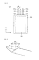
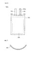
- FIGS. 1 and 2 are an exploded perspective view and a front view of a secondary battery 100 according to an embodiment of the present invention.
- FIG. 3 is a perspective view of an electrode tab 400 according to this embodiment of the present invention.
- the secondary battery 100 includes an enclosure in the form of a pouch 200 and an electrode assembly 300 accommodated in the pouch 200.
- the pouch 200 has an integrally formed substantially box-like shape and includes a first pouch portion 210 and a second pouch portion 200 that are foldable about a short edge thereof. A recess in which the electrode assembly 300 is accommodated is formed at a central portion of the first pouch portion 210 by pressing.
- the pouch 200 has a triple layer including a nylon layer, an aluminum thin film, and a polyolefin resin layer.
- the electrode assembly 300 includes a first electrode plate 310, a second electrode plate 320, and a separator 330 interposed between the first electrode plate 310 and the second electrode plate 320.
- the first electrode plate 310, the second electrode plate 320, and the separator 330 are wound to form a jelly-roll configuration thereby.
- the electrode assembly 300 is sealed together with an electrolyte by the pouch 200.
- the first electrode plate 310 is formed by coating a first electrode active material such as lithium oxide on opposite sides of a first electrode collector formed with a thin film such as an aluminum foil.
- the second electrode plate 320 is formed by coating a second electrode active material such as carbon on opposite sides of a second electrode collector formed with a thin film such as a copper foil.
- a first electrode tab 400 is formed on one side of the first electrode plate 310 of the electrode assembly 300, and a second electrode tab 500 is formed on one side of the second electrode plate 320.
- the first electrode tab 400 and the second electrode tab 500 are disposed in parallel and are spaced apart from each other in the jelly-roll configuration. Some portions of the first electrode tab 400 and the second electrode tab 500 are exposed to the outside of the pouch 200 so that the first electrode tab 400 and the second electrode tab 500 are electrically connected to a protection circuit module (not shown).
- the first electrode tab 400 and the second electrode tab 500 are generally made of a metal such as aluminum, copper, or nickel, and have high electrical conductivities to minimize voltage drops.
- a first insulation tape 610 and a second insulation tape 620 are formed between the first electrode tab 400 and the pouch 200 and between the second electrode tab 500 and the pouch 200 respectively.
- the first insulation tape 610 and the second insulation tape 620 are attached to portions of the first electrode tab 400 and the second electrode tab 500 that make contact with the pouch 200 to prevent short-circuits between the electrode tabs and the pouch 200.
- the first electrode plate 310 and the first electrode tab 400 are the positive electrode and the second electrode plate 320 and the second electrode tab 500 is the negative electrode.
- the first electrode tab 400 is generally made of aluminum and the second electrode tab 500 is made of nickel.
- the X-direction and the Y-direction are the widthwise (W) and lengthwise (H) directions of the first electrode tab 400 and the second electrode tab 500.
- the first electrode tab 400 will be described for convenience's sake, but the second electrode tab 500 has the same characteristics as the first electrode tab 400.
- the first electrode tab 400 has a bent structure whose widthwise cross-section is V-shaped.
- a bending line 400a is formed at a central portion of the first electrode tab 400 along the lengthwise direction of the first electrode tab 400 by a jig or a press.
- a first side tab 400b and a second side tab 400c are bent about the bending line 400a.
- the first side tab 400b and the second side tab 400c form a specific angle between them.
- the "V" may be oriented in the opposite direction to that of this particular embodiment.
- a conventional electrode tab has a narrow width and a long length, and has a thin thickness of approximately 0.1 mm. Hence, the electrode tab may be deformed even by a very weak load. In addition, the electrode tab may be deformed even without an external force due to its structural characteristics. This increases the fraction of defective secondary batteries due to following processes after electrode tabs are deformed or are not arranged in proper positions.
- Strength generally relates to a maximum load or stress that can be applied to a member or a structure while maintaining the function of the member or the structure until the member or the structure is fractured, and is a natural value for measuring the properties of a material.
- rigidity is a property by which a loaded structure or member resists against deformation, and the values of rigidity are different according to the shape or support of the structure even in the case of the same material.
- Strength can be enhanced by an alloy, and rigidity can be enhanced through a modification of a structure as well as by an alloy.
- the rigidity of the first electrode tab 400 is increased by forming the bending line 400a at a central region of the electrode tab 400 along the lengthwise(H) direction of the first electrode tab 400 and making the first electrode tab 400 V-shaped.
- the first electrode tab 400 has the V-shaped bending structure, when an external load is applied to an upper portion, a front portion, and a rear portion of the first electrode tab 400, the first electrode tab 400 is not easily deformed as compared with a flat electrode tab. This is because the rigidity of the first electrode tab 400 is increased by the V-shaped structure of the first electrode tab 400.
- the fraction of defective secondary batteries can be reduced by minimizing deformation of the first electrode tab 400 due to external loads applied when the first electrode tab 400 is preliminarily charged and is welded to a terminal of a protection circuit module and the secondary battery 100 is moved.
- FIGS. 4 and 5 are perspective views of the secondary battery 100 and pre-chargers 810 and 820.
- the pre-charger 810 of FIG. 4 has blocks at portions thereof that make contact with the electrode tabs 400 and 500
- the pre-charger 820 of FIG. 5 has pins at portions thereof that make contact with the electrode tabs 400 and 500.
- the sizes of the electrode tabs 400 and 500 will differ according to the capacity of the secondary battery 100, the widths thereof will often tend to be 4 to 6 mm and 2 to 3 mm in the case of a secondary battery 100 of small capacity.
- the pre-chargers 810 and 820 and the electrode tabs 400 and 500 cannot make contact with each other, causing inferiority.
- the pin type pre-charger 820 since the pin type pre-charger 820 has small contact areas of the contact pins 821 with the electrode tabs 400 and 500, the electrode tabs 400 and 500 and the pre-charger 820 cannot make contact with each other when the electrode tabs 400 and 500 are normally arranged, causing inferiority.
- the contact inferiority between the pre-chargers 810 and 820 and the electrode tabs 400 and 500 is prevented by the V-shaped structure of the electrode tabs 400 and 500 that serves to minimize deformation of the electrode tabs 400 and 500 in the processes when the pre-charging is operated.
- the distance between an end of the first side tab 400b and an end of the second side tab 400c is preferably more than 0.5 mm.
- the width W of the bent first electrode tab 400 is preferably more than 0.5 mm.
- Four probe pins 811 are formed in portions of the block type pre-charger 810 that make contact with the first electrode tab 400, and the first electrode tab 400 needs to make contact with at least one of the four probe pins 811 to charge the secondary battery.
- the interval L between the two probe pins 811 located in a direction perpendicular to the length H of the first electrode tab 400 is in this case 0.5 mm
- the distance between an end of the first side tab 400b and an end of the second side tab 400c needs to be more than 0.5 mm to prevent contact errors of the first electrode tab 400 and the probe pins 811 in advance.
- Different pre-chargers have different dimensions, of course, so these dimensions are merely illustrative.
- the electrode tabs may also be deformed when contacted with the pre-chargers 810 and 820.
- the block type pre-charger 810 has wider contact areas with the electrode tabs than the pin type pre-charger 820, larger loads are transferred to the electrode tabs, deforming the electrode tabs and displacing the electrode tabs from their proper positions.
- the electrode tabs 400 and 500 have V-shaped bending structures, deformation of the electrode tabs 400 and 500 can be minimized by enabling the electrode tabs 400 and 500 to support the pressure of the pre-charger during a pre-charging operation, and thus deformation of the electrode tabs 400 and 500 and deviation of the electrode tabs 400 and 500 from proper positions can be minimized during movement of the secondary battery 100 and before the welding operation of the protection circuit module.
- FIG. 6 is a front view of a secondary battery 100 according to another embodiment of the present invention.
- a first electrode tab 400 is bent in a V-shape.
- the shape of the first electrode tab 400 of FIG. 6 is the same as that of the electrode tab 400 illustrated in FIGS. 1 to 5 .
- the second electrode tab 700 has no bending line.
- the first electrode tab 400 is a positive electrode tab, and may be made of the same material as that of a first electrode collector such as aluminum.
- Aluminum has high malleability and ductility as compared with the second electrode tab 400 made of nickel, but has low strength and rigidity.
- the rigidity of the electrode tab 400 is increased by forming a bending line 400a at a central portion of the first electrode tab 400 along the lengthwise direction of the first electrode tab 400.
- the second electrode tab may alternatively have a V-shape.
- the present invention is not limited by which electrode tab has a V-shape.
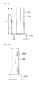
- FIGS. 7 to 13 are sectional views of electrode tabs 405, 410, 415, 420, 425, 430, and 435 according to other embodiments of the present invention.
- the sectional views are taken along the widthwise directions of the electrode tabs.
- the electrode tabs of FIGS. 7 to 13 are different from the first electrode tab 400 of FIGS. 1 to 5 only in the widthwise cross-sections, but the basic object and other descriptions of preventing deformation of the electrode tabs due to an external load and deviation of the electrode tabs from proper positions are the same as the electrode tab of FIGS. 1 to 6 . It should be understood that the widthwise structures of the electrode tabs of FIGS.
- first electrode tabs will be described for convenience' sake.
- the widthwise cross-section of the first electrode tab 405 has an arcuate profile with a specific curvature that is constant along the widthwise direction of the first electrode tab 405.
- the widthwise cross-section of the first electrode tab 410 has three bending lines 410a, 410b, and 410c along the lengthwise direction of the first electrode tab.
- the first electrode tab 410 has a W-shaped widthwise cross-section by the existence of the bending lines 410a, 410b, and 410c.
- first electrode tab 410 Since the first electrode tab 410 is bent twice more as compared with the first electrode tab 400 of FIGS. 1 to 5 , deformation of the first electrode tab 410 due to an external load can be remarkably prevented.
- protrusions 415a, 420a, and 425a are formed at widthwise central portions C of the first electrode tabs 415, 420, and 425.
- the protrusions 415a, 420a, and 425a are machined at central portions of the first electrode tabs 415, 420, and 425 along the lengthwise directions of the first electrode tabs 415, 420, and 425 by a jig or a press.
- the widthwise cross-sections of the protrusions 415a, 420a, and 425a have an arc shape, a rectangular shape, and a triangular shape.
- Other rectilinear and arcuate formations are equally suitable for the protrusions and it is possible to include a plurality of such protrusions of similar or different profiles within a single tab.
- the deformation of the first electrode taps 415, 420, and 425 can be minimized when the first electrode taps 415, 420, and 425 receive the external loads because the protrusions 415a, 420a, and 425a increase the rigidity of the first electrode tabs 415, 420, and 425.
- first electrode tabs 430 and 435 have corrugated shapes.
- the first electrode tab 430 of FIG. 12 has sinusoidal corrugations
- the first electrode tab 435 of FIG. 13 has saw-toothed corrugations whose bent portions have a specific angle.
- the wavy or zigzag shapes of the first electrode tabs 430 and 435 are regularly formed, but may also be irregularly formed.
- the deformation of the first electrode tabs 430 and 435 can be minimized when the first electrode tab 430 and 435 receive the external loads because the corrugations increase the rigidity of the first electrode tabs 430, and 435.
- FIGS. 14 to 16 are front views of electrode tabs 450, 455, and 460 according to other embodiments of the present invention.
- the electrode tabs of FIGS. 14 to 16 are different from the first electrode tabs 400 and 500 of FIGS. 1 to 5 only in the positions of the bending lines and the lengths of the bending lines, but the basic object and other descriptions of preventing deformation of the electrode tabs due to an external load and deviation of the electrode tabs from proper positions are the same as the electrode tab of FIGS. 1 to 6 .
- the electrode tabs of FIGS. 14 to 16 may have alternative widthwise cross-sections, such as those of FIGS. 7 to 13 , instead of the V-shapes.
- first electrode tabs will be described for convenience' sake.
- the length of the first electrode tab 450 is classified into an upper region L1, a central region L2, and a lower region L3 of the first electrode tab 450.
- the upper region L1 of the first electrode tab 450 is from the top end of the first electrode tab 450 to a position one third from the top end of the first electrode tab 450.
- the central region L2 of the first electrode tab 450 is from a position one third from the top end of the first electrode tab 450 to two thirds from the top end of the first electrode tab 450.
- the lower region L3 of the first electrode tab 450 is from a position two thirds from the top end of the first electrode tab 450 to the top end of an insulation tape 610.
- the bending line 450a and the V shape of the first electrode tab 450 are formed at the upper region L1 and the central region L2 of the first electrode tab 450.
- the portion of the first electrode tab 450 below the lower region L3 is supported by the pouch and the insulation tape 610.
- the pouch and the insulation tape 610 support some portions of the first electrode tab 450 that are not exposed from the insulation tape 610 to the outside, the lower region L3 of the first electrode tab 450 can maintain its rigidity even without a bending line and a V-shaped bending structure.
- the length of a first electrode tab 455 is classified into an upper region L4 and a lower region L5.
- the upper region L4 of the first electrode tab 455 is from the top end of the first electrode tab 455 to a position one half from the top end of the first electrode tab 455 and the lower region L5 of the first electrode tab 455 is from a position one half from the top end of the first electrode tab 455 to the top end of an insulation tape 610.
- a bending line 455a and a V-shaped structure are formed in the upper region L4 of the first electrode tab 455.
- the portion of the first electrode tab 455 below the lower region L5 is supported by the pouch and the insulation tape 610.
- the pouch and the insulation tape 610 support some portions of the first electrode tab 455 that are not exposed from the insulation tape 610 to the outside, the lower region L5 of the first electrode tab 455 can maintain its rigidity even without a bending line and a V-shaped bending structure.
- bending lines 460a and V-shaped structures are located at random.
- the positions, sizes, shapes of the bending lines 460a and the V-shaped structures are not particularly limited only if the electrode tab 460 can maintain its rigidity.
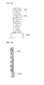
- FIGS. 17a and 17b show a plan view and a lengthwise sectional view of a first electrode tab 470 according to a further embodiment of the invention.
- the electrode tab 470 is non-planar, as in the previous embodiments. However, in this case, simple bend lines are not used. Instead, the electrode tab 470 comprises a series of generally rectangular recesses 475. These recesses 475 provide rigidity to the tab 470 in a similar manner to the bends of the previous embodiments.
- the recesses 475 are generally rectangular in their shape, but many other shapes are equally suitable. Furthermore, although the recesses are arranged in three columns and eleven rows in this embodiment, it is important to understand that more or fewer rows or columns can be included.
- FIGS. 18a and 18b are a plan view and a sectional view of a further embodiment of an electrode tab 480 in accordance with the invention.
- the electrode tab 480 includes a single rectangular recess 485.
- the recess 485 in parts increased rigidity to the electrode tab 480 in a similar manner to previous embodiments. It will be noted that this electrode tab is, once again, non-planar.
- the recess is generally rectangular, many other shapes can be used for the recess.
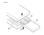
- FIG. 19 is a perspective view illustrating a method of bending electrode tabs 400 and 500 according to an embodiment of the present invention.
- a jig or press 900 has a saw-toothed shape to make the electrode tabs 400 and 500 V-shaped.
- the shapes of the electrode tabs of FIGS. 7 to 13 may be formed by manufacturing the jig or press in correspondence to them.
- the bent electrode tabs 400 and 500 may be flattened when they are pressed by a welding jig during their coupling to a terminal (not shown) of a protection circuit module (not shown).
- the non-planar structures of the electrode tabs according to the above-mentioned embodiments of the present invention increase the rigidities of the electrode tabs, minimizing deformation of the electrode tabs and deviation of the electrode tabs from their proper positions. Accordingly, the fraction of defective secondary batteries can be reduced by locating electrode tabs at proper positions during pre-charging operations of the electrode tabs and welding of the electrode tabs to protection circuit modules.
Landscapes
- Chemical & Material Sciences (AREA)
- Chemical Kinetics & Catalysis (AREA)
- Electrochemistry (AREA)
- General Chemical & Material Sciences (AREA)
- Engineering & Computer Science (AREA)
- Manufacturing & Machinery (AREA)
- Materials Engineering (AREA)
- Connection Of Batteries Or Terminals (AREA)
- Secondary Cells (AREA)
- Sealing Battery Cases Or Jackets (AREA)
Abstract
Description
- The present invention relates to a secondary battery.
- Lithium ion secondary batteries are classified as polygonal secondary batteries, cylindrical secondary batteries or pouch secondary batteries according to their structures.
- A pouch secondary battery typically includes an electrode assembly, a pouch surrounding the electrode assembly, a protection circuit module and a case.
- A polygonal or cylindrical secondary battery typically includes an electrode assembly in a can, a protection circuit module and a cover.
- Particularly in the case of a pouch secondary battery, but also in the case of other structures, the electrode assembly comprises one or more electrode tabs that project from the assembly. These tabs are somewhat vulnerable as they are made from relatively thin material and hence they can be deformed by even a relatively weak load. In addition, the tabs may be deformed even without the application of an external force. As a consequence, an undesirably high proportion of manufacturing and assembly defects can occur.
- The present invention seeks to provide a secondary battery including an electrode tab that cannot be easily deformed by an external load or displaced from its proper position.
- Accordingly, the invention provides a seconedary battery as set out in
Claim 1. Preferred features of the invention are set out in Claims 2 to 18.
According to the present invention, deformation of an electrode tab due to an external load and deviation of the electrode tab from a proper position can be prevented due to increased rigidity of the electrode tab. As a consequence, contact errors can be prevented when the electrode tab makes contact with a pre-charger during a pre-charging operation of the secondary battery and welding errors can be minimized between a terminal of a protection circuit module and the electrode tab when the electrode tab is welded to the protection circuit module. - Embodiments of the invention will be described by way of example and with reference to the accompanying drawings in which:-
-
FIG. 1 is an exploded perspective view of a secondary battery according to an embodiment of the present invention; -
FIG. 2 is a front view of the secondary battery ofFIG. 1 ; -
FIG. 3 is a perspective view of an electrode tab of the secondary battery ofFIG. 1 ; -
FIGS. 4 and 5 are perspective views of the secondary battery ofFigure 1 and pre-chargers; -
FIG. 6 is a front view of a secondary battery according to another embodiment of the present invention; -
FIGS. 7 to 13 are sectional views of electrode tabs secondary batteries according to other embodiments of the present invention; -
FIGS. 14 to 16 are front views of electrode tabs of a secondary batteries according to other embodiments of the present invention; -
FIGS. 17a to 18b are views of electrode tabs of secondary batteries according to still further embodiments of the invention; and -
FIG. 19 is a perspective view illustrating a method of bending electrode tabs of a secondary battery according to an embodiment of the present invention. - Hereinafter, embodiments of the present invention will be described in detail with reference to the accompanying drawings. Although pouch secondary batteries are described as embodiments of the present invention, the scope of the present invention is not limited thereto.
-
FIGS. 1 and2 are an exploded perspective view and a front view of asecondary battery 100 according to an embodiment of the present invention.FIG. 3 is a perspective view of anelectrode tab 400 according to this embodiment of the present invention. - Referring to
FIGS. 1 to 3 , thesecondary battery 100 includes an enclosure in the form of apouch 200 and anelectrode assembly 300 accommodated in thepouch 200. - The
pouch 200 has an integrally formed substantially box-like shape and includes afirst pouch portion 210 and asecond pouch portion 200 that are foldable about a short edge thereof. A recess in which theelectrode assembly 300 is accommodated is formed at a central portion of thefirst pouch portion 210 by pressing. Thepouch 200 has a triple layer including a nylon layer, an aluminum thin film, and a polyolefin resin layer. - The
electrode assembly 300 includes afirst electrode plate 310, asecond electrode plate 320, and aseparator 330 interposed between thefirst electrode plate 310 and thesecond electrode plate 320. Thefirst electrode plate 310, thesecond electrode plate 320, and theseparator 330 are wound to form a jelly-roll configuration thereby. Theelectrode assembly 300 is sealed together with an electrolyte by thepouch 200. - The
first electrode plate 310 is formed by coating a first electrode active material such as lithium oxide on opposite sides of a first electrode collector formed with a thin film such as an aluminum foil. Thesecond electrode plate 320 is formed by coating a second electrode active material such as carbon on opposite sides of a second electrode collector formed with a thin film such as a copper foil. - A
first electrode tab 400 is formed on one side of thefirst electrode plate 310 of theelectrode assembly 300, and asecond electrode tab 500 is formed on one side of thesecond electrode plate 320. Thefirst electrode tab 400 and thesecond electrode tab 500 are disposed in parallel and are spaced apart from each other in the jelly-roll configuration. Some portions of thefirst electrode tab 400 and thesecond electrode tab 500 are exposed to the outside of thepouch 200 so that thefirst electrode tab 400 and thesecond electrode tab 500 are electrically connected to a protection circuit module (not shown). Thefirst electrode tab 400 and thesecond electrode tab 500 are generally made of a metal such as aluminum, copper, or nickel, and have high electrical conductivities to minimize voltage drops. - A
first insulation tape 610 and asecond insulation tape 620 are formed between thefirst electrode tab 400 and thepouch 200 and between thesecond electrode tab 500 and thepouch 200 respectively. Thefirst insulation tape 610 and thesecond insulation tape 620 are attached to portions of thefirst electrode tab 400 and thesecond electrode tab 500 that make contact with thepouch 200 to prevent short-circuits between the electrode tabs and thepouch 200. Hereinafter, it is assumed that thefirst electrode plate 310 and thefirst electrode tab 400 are the positive electrode and thesecond electrode plate 320 and thesecond electrode tab 500 is the negative electrode. In this case, thefirst electrode tab 400 is generally made of aluminum and thesecond electrode tab 500 is made of nickel. InFIG. 2 , the X-direction and the Y-direction are the widthwise (W) and lengthwise (H) directions of thefirst electrode tab 400 and thesecond electrode tab 500. Hereinafter, thefirst electrode tab 400 will be described for convenience's sake, but thesecond electrode tab 500 has the same characteristics as thefirst electrode tab 400. - The
first electrode tab 400 has a bent structure whose widthwise cross-section is V-shaped. Abending line 400a is formed at a central portion of thefirst electrode tab 400 along the lengthwise direction of thefirst electrode tab 400 by a jig or a press. Afirst side tab 400b and asecond side tab 400c are bent about thebending line 400a. Thefirst side tab 400b and thesecond side tab 400c form a specific angle between them. The "V" may be oriented in the opposite direction to that of this particular embodiment. - A conventional electrode tab has a narrow width and a long length, and has a thin thickness of approximately 0.1 mm. Hence, the electrode tab may be deformed even by a very weak load. In addition, the electrode tab may be deformed even without an external force due to its structural characteristics. This increases the fraction of defective secondary batteries due to following processes after electrode tabs are deformed or are not arranged in proper positions.
- Strength generally relates to a maximum load or stress that can be applied to a member or a structure while maintaining the function of the member or the structure until the member or the structure is fractured, and is a natural value for measuring the properties of a material. Meanwhile, rigidity is a property by which a loaded structure or member resists against deformation, and the values of rigidity are different according to the shape or support of the structure even in the case of the same material. Generally, as strength increases, rigidity also increases. Strength can be enhanced by an alloy, and rigidity can be enhanced through a modification of a structure as well as by an alloy.
- In this embodiment of the present invention, the rigidity of the
first electrode tab 400 is increased by forming thebending line 400a at a central region of theelectrode tab 400 along the lengthwise(H) direction of thefirst electrode tab 400 and making the first electrode tab 400 V-shaped. As thefirst electrode tab 400 has the V-shaped bending structure, when an external load is applied to an upper portion, a front portion, and a rear portion of thefirst electrode tab 400, thefirst electrode tab 400 is not easily deformed as compared with a flat electrode tab. This is because the rigidity of thefirst electrode tab 400 is increased by the V-shaped structure of thefirst electrode tab 400. - As a consequence of this structure, the fraction of defective secondary batteries can be reduced by minimizing deformation of the
first electrode tab 400 due to external loads applied when thefirst electrode tab 400 is preliminarily charged and is welded to a terminal of a protection circuit module and thesecondary battery 100 is moved. -
FIGS. 4 and 5 are perspective views of thesecondary battery 100 and pre-chargers 810 and 820. Thepre-charger 810 ofFIG. 4 has blocks at portions thereof that make contact with theelectrode tabs pre-charger 820 ofFIG. 5 has pins at portions thereof that make contact with theelectrode tabs - Referring to
FIGS. 4 and 5 together withFIG. 3 , although the sizes of theelectrode tabs secondary battery 100, the widths thereof will often tend to be 4 to 6 mm and 2 to 3 mm in the case of asecondary battery 100 of small capacity. Hence, if theelectrode tabs pre-chargers electrode tabs pin type pre-charger 820 has small contact areas of the contact pins 821 with theelectrode tabs electrode tabs electrode tabs - However, the contact inferiority between the pre-chargers 810 and 820 and the
electrode tabs electrode tabs electrode tabs - In the case of the
first electrode tab 400, the distance between an end of thefirst side tab 400b and an end of thesecond side tab 400c is preferably more than 0.5 mm. In other words, the width W of the bentfirst electrode tab 400 is preferably more than 0.5 mm. Four probe pins 811 are formed in portions of theblock type pre-charger 810 that make contact with thefirst electrode tab 400, and thefirst electrode tab 400 needs to make contact with at least one of the fourprobe pins 811 to charge the secondary battery. Since the interval L between the two probe pins 811 located in a direction perpendicular to the length H of thefirst electrode tab 400 is in this case 0.5 mm, the distance between an end of thefirst side tab 400b and an end of thesecond side tab 400c needs to be more than 0.5 mm to prevent contact errors of thefirst electrode tab 400 and the probe pins 811 in advance. Different pre-chargers have different dimensions, of course, so these dimensions are merely illustrative. - The electrode tabs may also be deformed when contacted with the
pre-chargers block type pre-charger 810 has wider contact areas with the electrode tabs than thepin type pre-charger 820, larger loads are transferred to the electrode tabs, deforming the electrode tabs and displacing the electrode tabs from their proper positions. - However, according to this embodiment of the present invention, since the
electrode tabs electrode tabs electrode tabs electrode tabs electrode tabs secondary battery 100 and before the welding operation of the protection circuit module. -
FIG. 6 is a front view of asecondary battery 100 according to another embodiment of the present invention. In this embodiment, only afirst electrode tab 400 is bent in a V-shape. The shape of thefirst electrode tab 400 ofFIG. 6 is the same as that of theelectrode tab 400 illustrated inFIGS. 1 to 5 . Thesecond electrode tab 700 has no bending line. - The
first electrode tab 400 is a positive electrode tab, and may be made of the same material as that of a first electrode collector such as aluminum. Aluminum has high malleability and ductility as compared with thesecond electrode tab 400 made of nickel, but has low strength and rigidity. - As in the previous embodiment, the rigidity of the
electrode tab 400 is increased by forming abending line 400a at a central portion of thefirst electrode tab 400 along the lengthwise direction of thefirst electrode tab 400. - Although not illustrated, the second electrode tab may alternatively have a V-shape. However, the present invention is not limited by which electrode tab has a V-shape.
-
FIGS. 7 to 13 are sectional views ofelectrode tabs FIGS. 7 to 13 , the sectional views are taken along the widthwise directions of the electrode tabs. The electrode tabs ofFIGS. 7 to 13 are different from thefirst electrode tab 400 ofFIGS. 1 to 5 only in the widthwise cross-sections, but the basic object and other descriptions of preventing deformation of the electrode tabs due to an external load and deviation of the electrode tabs from proper positions are the same as the electrode tab ofFIGS. 1 to 6 . It should be understood that the widthwise structures of the electrode tabs ofFIGS. 7 to 13 are the same over the overall lengthwise direction but they may alternatively be formed at specific positions of the lengths of the electrode tabs. It is also possible to include two or more different cross-sectional profiles within a single tab. Hereinafter, first electrode tabs will be described for convenience' sake. - Referring to
FIG. 7 , the widthwise cross-section of thefirst electrode tab 405 according to the embodiment of the present invention has an arcuate profile with a specific curvature that is constant along the widthwise direction of thefirst electrode tab 405. - Since the curvature of the
first electrode tab 405 is constant, deformation of thefirst electrode tab 405 can be minimized by uniformly distributing an external load. - Referring to
FIG. 8 , the widthwise cross-section of thefirst electrode tab 410 according to the embodiment of the present invention has threebending lines first electrode tab 410 has a W-shaped widthwise cross-section by the existence of thebending lines - Since the
first electrode tab 410 is bent twice more as compared with thefirst electrode tab 400 ofFIGS. 1 to 5 , deformation of thefirst electrode tab 410 due to an external load can be remarkably prevented. - Other rectilinear and arcuate cross-sectional profiles are equally suitable.
- Referring to
FIGS. 9 to 11 , in the widthwise cross-sections of thefirst electrode tabs protrusions first electrode tabs protrusions first electrode tabs first electrode tabs - The deformation of the first electrode taps 415, 420, and 425 can be minimized when the first electrode taps 415, 420, and 425 receive the external loads because the
protrusions first electrode tabs - Referring to
FIGS. 12 and 13 , the widthwise cross-sections offirst electrode tabs first electrode tab 430 ofFIG. 12 has sinusoidal corrugations, and thefirst electrode tab 435 ofFIG. 13 has saw-toothed corrugations whose bent portions have a specific angle. InFIGS. 12 and 13 , the wavy or zigzag shapes of thefirst electrode tabs - The deformation of the
first electrode tabs first electrode tab first electrode tabs -
FIGS. 14 to 16 are front views ofelectrode tabs FIGS. 14 to 16 are different from thefirst electrode tabs FIGS. 1 to 5 only in the positions of the bending lines and the lengths of the bending lines, but the basic object and other descriptions of preventing deformation of the electrode tabs due to an external load and deviation of the electrode tabs from proper positions are the same as the electrode tab ofFIGS. 1 to 6 . It should be understood that the electrode tabs ofFIGS. 14 to 16 may have alternative widthwise cross-sections, such as those ofFIGS. 7 to 13 , instead of the V-shapes. Hereinafter, first electrode tabs will be described for convenience' sake. - Referring to
FIG. 14 , the length of thefirst electrode tab 450 according to the embodiment of the present invention is classified into an upper region L1, a central region L2, and a lower region L3 of thefirst electrode tab 450. The upper region L1 of thefirst electrode tab 450 is from the top end of thefirst electrode tab 450 to a position one third from the top end of thefirst electrode tab 450. The central region L2 of thefirst electrode tab 450 is from a position one third from the top end of thefirst electrode tab 450 to two thirds from the top end of thefirst electrode tab 450. The lower region L3 of thefirst electrode tab 450 is from a position two thirds from the top end of thefirst electrode tab 450 to the top end of aninsulation tape 610. - The
bending line 450a and the V shape of thefirst electrode tab 450 are formed at the upper region L1 and the central region L2 of thefirst electrode tab 450. The portion of thefirst electrode tab 450 below the lower region L3 is supported by the pouch and theinsulation tape 610. Hence, since the pouch and theinsulation tape 610 support some portions of thefirst electrode tab 450 that are not exposed from theinsulation tape 610 to the outside, the lower region L3 of thefirst electrode tab 450 can maintain its rigidity even without a bending line and a V-shaped bending structure. - Referring to
FIG. 15 , the length of afirst electrode tab 455 according to the embodiment of the present invention is classified into an upper region L4 and a lower region L5. The upper region L4 of thefirst electrode tab 455 is from the top end of thefirst electrode tab 455 to a position one half from the top end of thefirst electrode tab 455 and the lower region L5 of thefirst electrode tab 455 is from a position one half from the top end of thefirst electrode tab 455 to the top end of aninsulation tape 610. - A
bending line 455a and a V-shaped structure are formed in the upper region L4 of thefirst electrode tab 455. The portion of thefirst electrode tab 455 below the lower region L5 is supported by the pouch and theinsulation tape 610. Hence, since the pouch and theinsulation tape 610 support some portions of thefirst electrode tab 455 that are not exposed from theinsulation tape 610 to the outside, the lower region L5 of thefirst electrode tab 455 can maintain its rigidity even without a bending line and a V-shaped bending structure. - Referring to
FIG. 16 , in afirst electrode tab 460 according to another embodiment of the present invention, bendinglines 460a and V-shaped structures are located at random. The positions, sizes, shapes of thebending lines 460a and the V-shaped structures are not particularly limited only if theelectrode tab 460 can maintain its rigidity. -
FIGS. 17a and 17b show a plan view and a lengthwise sectional view of afirst electrode tab 470 according to a further embodiment of the invention. - In this embodiment, the
electrode tab 470 is non-planar, as in the previous embodiments. However, in this case, simple bend lines are not used. Instead, theelectrode tab 470 comprises a series of generally rectangular recesses 475. Theserecesses 475 provide rigidity to thetab 470 in a similar manner to the bends of the previous embodiments. - It will seem that the
recesses 475 are generally rectangular in their shape, but many other shapes are equally suitable. Furthermore, although the recesses are arranged in three columns and eleven rows in this embodiment, it is important to understand that more or fewer rows or columns can be included. -
FIGS. 18a and 18b are a plan view and a sectional view of a further embodiment of anelectrode tab 480 in accordance with the invention. In this case, theelectrode tab 480 includes a singlerectangular recess 485. Therecess 485 in parts increased rigidity to theelectrode tab 480 in a similar manner to previous embodiments. It will be noted that this electrode tab is, once again, non-planar. Although the recess is generally rectangular, many other shapes can be used for the recess. -
FIG. 19 is a perspective view illustrating a method of bendingelectrode tabs - Referring to
FIG. 19 , after anelectrode assembly 300 is sealed by apouch 200, portions of theelectrode assembly 300 that protrude to the outside of thepouch 200 are pressed by a jig orpress 900. In the embodiment of the present invention, the jig orpress 900 has a saw-toothed shape to make theelectrode tabs 400 and 500 V-shaped. However, it is apparent that the shapes of the electrode tabs ofFIGS. 7 to 13 may be formed by manufacturing the jig or press in correspondence to them. - The
bent electrode tabs - The non-planar structures of the electrode tabs according to the above-mentioned embodiments of the present invention increase the rigidities of the electrode tabs, minimizing deformation of the electrode tabs and deviation of the electrode tabs from their proper positions. Accordingly, the fraction of defective secondary batteries can be reduced by locating electrode tabs at proper positions during pre-charging operations of the electrode tabs and welding of the electrode tabs to protection circuit modules.
- It should be understood that the specifically described shapes and cross-sectional profiles are mere examples, and many other shapes and profiles are possible. It is also possible to have different configurations on different tabs within the same battery pack and it is possible to include a mixture of formations on a single tab.
- Although the embodiments of the present invention have been described in detail hereinabove, it should be understood that many variations and modifications of the basic inventive concept herein described will still fall within the spirit and scope of the present invention as defined in the appended claims.
Claims (18)
- A secondary battery comprising:an electrode assembly having a first electrode plate and a second electrode plate, each electrode plate being provided with a respective electrode tab that extends from the electrode plate;wherein a portion of one of the electrode tabs is non-planar.
- A secondary battery according to Claim 1, wherein the non-planar portion comprises a bend.
- A secondary battery according to Claim 2, wherein the non-planar portion comprises two sub-portions, one said sub-portion being situated on either side of the bend.
- A secondary battery according to Claim 2 or 3, wherein the bend extends along an axis arranged in a lengthwise direction of the electrode tab in which the bend is provided.
- A secondary battery according to Claim 4, wherein the axis extends in a direction substantially parallel to the longitudinal axis of the electrode tab in which the bend is provided.
- A secondary battery according to one of Claims 2 to 5, wherein at least part of the non-planar portion has an arcuate cross-section.
- A secondary battery according to one of Claims 2 to 6, wherein at least part of the non-planar portion has a rectilinear cross-section.
- A secondary battery according to Claim 7, wherein the rectilinear cross-section is V-shaped, W-shaped or rectangular.
- A secondary battery according to one of Claims 2 to 8, wherein the non-planar portion comprises one or more corrugations.
- A secondary battery according to Claim 9, wherein the corrugations are saw-toothed or sinusoidal.
- A secondary battery according to any preceding claim, wherein the electrode assembly is accommodated within an enclosure, and the non-planar portion extends along substantially the entire length of a part of the electrode tab that projects from the enclosure.
- A secondary battery according to any one of Claims 1 to 10, wherein the electrode assembly is accommodated within an enclosure, and the non-planar portion extends along a portion of the electrode tab that occupies a part of the length of a part of the electrode tab that projects from the enclosure.
- A secondary battery according to Claim 12, wherein the non-planar portion extends along a portion of the electrode tab that occupies from a half to two thirds of the length of a part of the electrode tab that projects from the enclosure.
- A secondary battery according to any preceding claim, wherein the said electrode having the non-planar portion comprises one or more additional non-planar portions.
- A Secondary battery according to any preceding claim, wherein the electrode tab has a width of from 2 mm to 6 mm.
- A secondary battery according to any preceding claim, wherein a portion of the other electrode tab is non-planar.
- A secondary battery according to any preceding claim, wherein the non-planar portion comprises one or more recesses.
- A secondary battery according to Claim 17, wherein the non-planar portion comprises a plurality of recesses that extend over substantially the whole of the non-planar portion.
Applications Claiming Priority (2)
| Application Number | Priority Date | Filing Date | Title |
|---|---|---|---|
| US14204708P | 2008-12-31 | 2008-12-31 | |
| US12/646,966 US9153813B2 (en) | 2008-12-31 | 2009-12-23 | Secondary battery |
Publications (2)
| Publication Number | Publication Date |
|---|---|
| EP2209150A1 true EP2209150A1 (en) | 2010-07-21 |
| EP2209150B1 EP2209150B1 (en) | 2013-01-23 |
Family
ID=41820360
Family Applications (1)
| Application Number | Title | Priority Date | Filing Date |
|---|---|---|---|
| EP09252926A Not-in-force EP2209150B1 (en) | 2008-12-31 | 2009-12-30 | Secondary battery |
Country Status (5)
| Country | Link |
|---|---|
| US (1) | US9153813B2 (en) |
| EP (1) | EP2209150B1 (en) |
| JP (1) | JP5279697B2 (en) |
| KR (1) | KR20100080414A (en) |
| CN (1) | CN101771141B (en) |
Cited By (2)
| Publication number | Priority date | Publication date | Assignee | Title |
|---|---|---|---|---|
| EP2399310A1 (en) * | 2009-02-23 | 2011-12-28 | Li-tec Battery GmbH | Electrochemical cell and contact element for making contact with it |
| EP4579932A4 (en) * | 2022-09-23 | 2026-03-04 | Lg Energy Solution Ltd | Disconnection preventive battery module |
Families Citing this family (30)
| Publication number | Priority date | Publication date | Assignee | Title |
|---|---|---|---|---|
| WO2013036802A1 (en) | 2011-09-07 | 2013-03-14 | 24M Technologies, Inc. | Stationary semi-solid battery module and method of manufacture |
| KR101937171B1 (en) * | 2012-03-06 | 2019-01-10 | 엘지전자 주식회사 | Battery Pack |
| US9401501B2 (en) | 2012-05-18 | 2016-07-26 | 24M Technologies, Inc. | Electrochemical cells and methods of manufacturing the same |
| JP6045286B2 (en) * | 2012-10-15 | 2016-12-14 | 日立オートモティブシステムズ株式会社 | Cylindrical energy storage device |
| KR101596269B1 (en) * | 2013-02-13 | 2016-02-23 | 주식회사 엘지화학 | Battery Cell of Novel Structure |
| JP6194728B2 (en) * | 2013-10-01 | 2017-09-13 | トヨタ自動車株式会社 | Battery manufacturing method |
| TWI673899B (en) | 2013-10-22 | 2019-10-01 | 日商半導體能源研究所股份有限公司 | Secondary battery and electronic device |
| US20150138699A1 (en) | 2013-11-15 | 2015-05-21 | Semiconductor Energy Laboratory Co., Ltd. | Electronic device |
| EP3216067B1 (en) | 2014-11-05 | 2021-09-15 | 24m Technologies, Inc. | Electrochemical cells having semi-solid electrodes and methods of manufacturing the same |
| EP4668405A3 (en) | 2015-06-18 | 2026-03-25 | 24M Technologies, Inc. | Single pouch battery cells and methods of manufacture |
| KR102514594B1 (en) * | 2015-08-13 | 2023-03-27 | 삼성전자주식회사 | Exterior package for flexible electrochemical device and electrochemical device including the exterior package |
| KR102463895B1 (en) * | 2015-09-14 | 2022-11-04 | 삼성전자주식회사 | Electrode stack structure comprising multi-tap and Battery comprising electrode stack structure |
| US9905847B2 (en) | 2015-11-18 | 2018-02-27 | GM Global Technology Operations LLC | Forming electrode active materials |
| JP6450349B2 (en) * | 2016-07-05 | 2019-01-09 | 積水化学工業株式会社 | Method for producing lithium ion secondary battery |
| KR102112693B1 (en) * | 2016-08-09 | 2020-05-19 | 주식회사 엘지화학 | Secondary battery |
| KR101858680B1 (en) * | 2016-08-11 | 2018-05-16 | (주)테크랜드 | Apparatus and method for folding cells of secondary cell battery |
| KR102092117B1 (en) * | 2017-04-12 | 2020-03-23 | 주식회사 엘지화학 | Electrode Tab Coupling Member and Electrode Tab Coupling Assembly comprising the same |
| CN111712942A (en) | 2018-01-08 | 2020-09-25 | 24M技术公司 | Electrochemical cell including permselective membrane, system and method of making the same |
| US11631920B2 (en) | 2019-06-27 | 2023-04-18 | 24M Technologies, Inc. | Dual electrolyte electrochemical cells, systems, and methods of manufacturing the same |
| US11742525B2 (en) | 2020-02-07 | 2023-08-29 | 24M Technologies, Inc. | Divided energy electrochemical cell systems and methods of producing the same |
| KR102782785B1 (en) * | 2020-05-20 | 2025-03-18 | 주식회사 엘지에너지솔루션 | Secondary battery and manufacturing method for the same |
| US12381277B2 (en) | 2020-06-17 | 2025-08-05 | 24M Technologies, Inc. | Electrochemical cells with flame retardant mechanism and methods of producing the same |
| JP7412394B2 (en) * | 2021-08-27 | 2024-01-12 | プライムプラネットエナジー&ソリューションズ株式会社 | battery |
| JP7600979B2 (en) * | 2021-12-28 | 2024-12-17 | トヨタ自動車株式会社 | battery |
| US20240148060A1 (en) * | 2022-09-19 | 2024-05-09 | Altria Client Services Llc | Heat-not-burn (hnb) aerosol-generating devices and capsules having electrical contact pads with surface discontinuities |
| WO2024064669A1 (en) * | 2022-09-19 | 2024-03-28 | Altria Client Services Llc | Capsules having electrical contact pads with surface discontinuities and heat-not-burn (hnb) aerosol-generating devices including the same |
| USD1051071S1 (en) | 2022-11-07 | 2024-11-12 | Altria Client Services Llc | Set of electrical contact pads |
| KR20240070325A (en) * | 2022-11-14 | 2024-05-21 | 주식회사 엘지에너지솔루션 | Electrode Assembly Having Tab Bundle with Curved Shape and Apparatus for Forming Tab Bundle of Electrode Assembly for Manufacturing the Same |
| WO2024116623A1 (en) * | 2022-12-01 | 2024-06-06 | 株式会社村田製作所 | Battery |
| JP7841521B2 (en) * | 2023-10-11 | 2026-04-07 | トヨタ自動車株式会社 | Method for manufacturing laminated batteries, and laminated batteries |
Citations (3)
| Publication number | Priority date | Publication date | Assignee | Title |
|---|---|---|---|---|
| JP2003109579A (en) | 2001-09-27 | 2003-04-11 | Yuasa Corp | Battery |
| EP1717894A1 (en) | 2005-04-25 | 2006-11-02 | Samsung SDI Co., Ltd. | Cylindrical lithium secondary battery and method of fabricating the same |
| US20080241676A1 (en) | 2007-03-30 | 2008-10-02 | Tdk Corporation | Electrochemical device |
Family Cites Families (11)
| Publication number | Priority date | Publication date | Assignee | Title |
|---|---|---|---|---|
| JP2000077044A (en) | 1998-08-28 | 2000-03-14 | Mitsubishi Cable Ind Ltd | Sheet battery |
| JP2001243939A (en) | 2000-02-25 | 2001-09-07 | Nec Corp | Thin secondary battery, lead terminal for thin secondary battery, and method of manufacturing the same |
| JP4033445B2 (en) | 2002-04-03 | 2008-01-16 | Necトーキン株式会社 | Sealed battery |
| JP2005129393A (en) | 2003-10-24 | 2005-05-19 | Nissan Motor Co Ltd | Secondary battery |
| JP2005174691A (en) | 2003-12-10 | 2005-06-30 | Nissan Motor Co Ltd | Bipolar battery |
| JP4617672B2 (en) | 2003-12-26 | 2011-01-26 | トヨタ自動車株式会社 | Laminated battery module and manufacturing method thereof |
| KR100608103B1 (en) | 2004-02-14 | 2006-08-02 | 주식회사 나래나노텍 | Coupling Structure of Li-ion Polymer Secondary Battery Using Copper Electrode Terminal |
| JP2005340005A (en) | 2004-05-27 | 2005-12-08 | Nissan Motor Co Ltd | Secondary battery and assembled battery |
| JP2006019075A (en) | 2004-06-30 | 2006-01-19 | Nissan Motor Co Ltd | Flat battery and assembled battery using the battery |
| KR100726065B1 (en) * | 2004-12-22 | 2007-06-08 | 에스케이 주식회사 | High power lithium battery packs with high power lithium cells and high power lithium cells |
| KR20080034369A (en) | 2006-10-16 | 2008-04-21 | 삼성에스디아이 주식회사 | Pouch Type Lithium Secondary Battery |
-
2009
- 2009-12-23 US US12/646,966 patent/US9153813B2/en not_active Expired - Fee Related
- 2009-12-25 JP JP2009296188A patent/JP5279697B2/en not_active Expired - Fee Related
- 2009-12-28 KR KR1020090131612A patent/KR20100080414A/en not_active Ceased
- 2009-12-30 EP EP09252926A patent/EP2209150B1/en not_active Not-in-force
- 2009-12-30 CN CN200910258924.0A patent/CN101771141B/en not_active Expired - Fee Related
Patent Citations (3)
| Publication number | Priority date | Publication date | Assignee | Title |
|---|---|---|---|---|
| JP2003109579A (en) | 2001-09-27 | 2003-04-11 | Yuasa Corp | Battery |
| EP1717894A1 (en) | 2005-04-25 | 2006-11-02 | Samsung SDI Co., Ltd. | Cylindrical lithium secondary battery and method of fabricating the same |
| US20080241676A1 (en) | 2007-03-30 | 2008-10-02 | Tdk Corporation | Electrochemical device |
Cited By (2)
| Publication number | Priority date | Publication date | Assignee | Title |
|---|---|---|---|---|
| EP2399310A1 (en) * | 2009-02-23 | 2011-12-28 | Li-tec Battery GmbH | Electrochemical cell and contact element for making contact with it |
| EP4579932A4 (en) * | 2022-09-23 | 2026-03-04 | Lg Energy Solution Ltd | Disconnection preventive battery module |
Also Published As
| Publication number | Publication date |
|---|---|
| CN101771141B (en) | 2014-06-25 |
| JP2010157510A (en) | 2010-07-15 |
| CN101771141A (en) | 2010-07-07 |
| US9153813B2 (en) | 2015-10-06 |
| JP5279697B2 (en) | 2013-09-04 |
| EP2209150B1 (en) | 2013-01-23 |
| US20100167123A1 (en) | 2010-07-01 |
| KR20100080414A (en) | 2010-07-08 |
Similar Documents
| Publication | Publication Date | Title |
|---|---|---|
| EP2209150B1 (en) | Secondary battery | |
| US11742526B2 (en) | Rechargeable battery | |
| US12066503B2 (en) | Bus bar for battery cell connection, battery pack, and manufacturing method therefor | |
| US7993774B2 (en) | Conductive plate and secondary battery pack using conductive plate | |
| US9159505B2 (en) | Electric storage device | |
| KR101526457B1 (en) | Electrode Having Round Corner | |
| US12243987B2 (en) | Method for assembly of battery pack with compact shared PCM | |
| EP2348557B1 (en) | Secondary battery | |
| EP3806180A1 (en) | Battery module | |
| EP3675203B1 (en) | Secondary battery and battery module | |
| EP3675238B1 (en) | Secondary battery and battery module | |
| JP2023521499A (en) | Electrode assembly and secondary battery including the same | |
| KR102570970B1 (en) | Electrode assembly | |
| KR102951081B1 (en) | Battery module | |
| US20240283113A1 (en) | Current blocking structure applied to pouch type secondary battery | |
| KR102835811B1 (en) | Battery cell | |
| US10873067B2 (en) | Folding tab for ultra-thin battery cell connection | |
| US12555930B2 (en) | Member-joined structure, battery module, and battery pack | |
| US20120276425A1 (en) | Battery | |
| US20250385271A1 (en) | Secondary battery | |
| KR102858768B1 (en) | Battery module | |
| HK40117443A (en) | Nested protection circuit module battery pack | |
| EP4651278A1 (en) | Sealing block for preventing cracking of pouch-type battery case, method for sealing pouch-type battery case by using same, and pouch-type secondary battery manufactured by using same |
Legal Events
| Date | Code | Title | Description |
|---|---|---|---|
| PUAI | Public reference made under article 153(3) epc to a published international application that has entered the european phase |
Free format text: ORIGINAL CODE: 0009012 |
|
| 17P | Request for examination filed |
Effective date: 20100114 |
|
| AK | Designated contracting states |
Kind code of ref document: A1 Designated state(s): AT BE BG CH CY CZ DE DK EE ES FI FR GB GR HR HU IE IS IT LI LT LU LV MC MK MT NL NO PL PT RO SE SI SK SM TR |
|
| AX | Request for extension of the european patent |
Extension state: AL BA RS |
|
| 17Q | First examination report despatched |
Effective date: 20110603 |
|
| 17Q | First examination report despatched |
Effective date: 20110609 |
|
| GRAP | Despatch of communication of intention to grant a patent |
Free format text: ORIGINAL CODE: EPIDOSNIGR1 |
|
| GRAS | Grant fee paid |
Free format text: ORIGINAL CODE: EPIDOSNIGR3 |
|
| GRAA | (expected) grant |
Free format text: ORIGINAL CODE: 0009210 |
|
| AK | Designated contracting states |
Kind code of ref document: B1 Designated state(s): AT BE BG CH CY CZ DE DK EE ES FI FR GB GR HR HU IE IS IT LI LT LU LV MC MK MT NL NO PL PT RO SE SI SK SM TR |
|
| REG | Reference to a national code |
Ref country code: GB Ref legal event code: FG4D |
|
| REG | Reference to a national code |
Ref country code: CH Ref legal event code: EP |
|
| REG | Reference to a national code |
Ref country code: AT Ref legal event code: REF Ref document number: 595378 Country of ref document: AT Kind code of ref document: T Effective date: 20130215 Ref country code: CH Ref legal event code: EP |
|
| REG | Reference to a national code |
Ref country code: IE Ref legal event code: FG4D |
|
| REG | Reference to a national code |
Ref country code: DE Ref legal event code: R096 Ref document number: 602009012979 Country of ref document: DE Effective date: 20130321 |
|
| REG | Reference to a national code |
Ref country code: AT Ref legal event code: MK05 Ref document number: 595378 Country of ref document: AT Kind code of ref document: T Effective date: 20130123 |
|
| REG | Reference to a national code |
Ref country code: LT Ref legal event code: MG4D |
|
| REG | Reference to a national code |
Ref country code: NL Ref legal event code: VDEP Effective date: 20130123 |
|
| PG25 | Lapsed in a contracting state [announced via postgrant information from national office to epo] |
Ref country code: SE Free format text: LAPSE BECAUSE OF FAILURE TO SUBMIT A TRANSLATION OF THE DESCRIPTION OR TO PAY THE FEE WITHIN THE PRESCRIBED TIME-LIMIT Effective date: 20130123 Ref country code: BG Free format text: LAPSE BECAUSE OF FAILURE TO SUBMIT A TRANSLATION OF THE DESCRIPTION OR TO PAY THE FEE WITHIN THE PRESCRIBED TIME-LIMIT Effective date: 20130423 Ref country code: NO Free format text: LAPSE BECAUSE OF FAILURE TO SUBMIT A TRANSLATION OF THE DESCRIPTION OR TO PAY THE FEE WITHIN THE PRESCRIBED TIME-LIMIT Effective date: 20130423 Ref country code: IS Free format text: LAPSE BECAUSE OF FAILURE TO SUBMIT A TRANSLATION OF THE DESCRIPTION OR TO PAY THE FEE WITHIN THE PRESCRIBED TIME-LIMIT Effective date: 20130523 Ref country code: LT Free format text: LAPSE BECAUSE OF FAILURE TO SUBMIT A TRANSLATION OF THE DESCRIPTION OR TO PAY THE FEE WITHIN THE PRESCRIBED TIME-LIMIT Effective date: 20130123 Ref country code: BE Free format text: LAPSE BECAUSE OF FAILURE TO SUBMIT A TRANSLATION OF THE DESCRIPTION OR TO PAY THE FEE WITHIN THE PRESCRIBED TIME-LIMIT Effective date: 20130123 Ref country code: ES Free format text: LAPSE BECAUSE OF FAILURE TO SUBMIT A TRANSLATION OF THE DESCRIPTION OR TO PAY THE FEE WITHIN THE PRESCRIBED TIME-LIMIT Effective date: 20130504 Ref country code: AT Free format text: LAPSE BECAUSE OF FAILURE TO SUBMIT A TRANSLATION OF THE DESCRIPTION OR TO PAY THE FEE WITHIN THE PRESCRIBED TIME-LIMIT Effective date: 20130123 |
|
| PG25 | Lapsed in a contracting state [announced via postgrant information from national office to epo] |
Ref country code: GR Free format text: LAPSE BECAUSE OF FAILURE TO SUBMIT A TRANSLATION OF THE DESCRIPTION OR TO PAY THE FEE WITHIN THE PRESCRIBED TIME-LIMIT Effective date: 20130424 Ref country code: PT Free format text: LAPSE BECAUSE OF FAILURE TO SUBMIT A TRANSLATION OF THE DESCRIPTION OR TO PAY THE FEE WITHIN THE PRESCRIBED TIME-LIMIT Effective date: 20130523 Ref country code: FI Free format text: LAPSE BECAUSE OF FAILURE TO SUBMIT A TRANSLATION OF THE DESCRIPTION OR TO PAY THE FEE WITHIN THE PRESCRIBED TIME-LIMIT Effective date: 20130123 Ref country code: LV Free format text: LAPSE BECAUSE OF FAILURE TO SUBMIT A TRANSLATION OF THE DESCRIPTION OR TO PAY THE FEE WITHIN THE PRESCRIBED TIME-LIMIT Effective date: 20130123 Ref country code: PL Free format text: LAPSE BECAUSE OF FAILURE TO SUBMIT A TRANSLATION OF THE DESCRIPTION OR TO PAY THE FEE WITHIN THE PRESCRIBED TIME-LIMIT Effective date: 20130123 Ref country code: NL Free format text: LAPSE BECAUSE OF FAILURE TO SUBMIT A TRANSLATION OF THE DESCRIPTION OR TO PAY THE FEE WITHIN THE PRESCRIBED TIME-LIMIT Effective date: 20130123 Ref country code: SI Free format text: LAPSE BECAUSE OF FAILURE TO SUBMIT A TRANSLATION OF THE DESCRIPTION OR TO PAY THE FEE WITHIN THE PRESCRIBED TIME-LIMIT Effective date: 20130123 |
|
| PG25 | Lapsed in a contracting state [announced via postgrant information from national office to epo] |
Ref country code: HR Free format text: LAPSE BECAUSE OF FAILURE TO SUBMIT A TRANSLATION OF THE DESCRIPTION OR TO PAY THE FEE WITHIN THE PRESCRIBED TIME-LIMIT Effective date: 20130123 |
|
| PG25 | Lapsed in a contracting state [announced via postgrant information from national office to epo] |
Ref country code: RO Free format text: LAPSE BECAUSE OF FAILURE TO SUBMIT A TRANSLATION OF THE DESCRIPTION OR TO PAY THE FEE WITHIN THE PRESCRIBED TIME-LIMIT Effective date: 20130123 Ref country code: SK Free format text: LAPSE BECAUSE OF FAILURE TO SUBMIT A TRANSLATION OF THE DESCRIPTION OR TO PAY THE FEE WITHIN THE PRESCRIBED TIME-LIMIT Effective date: 20130123 Ref country code: CZ Free format text: LAPSE BECAUSE OF FAILURE TO SUBMIT A TRANSLATION OF THE DESCRIPTION OR TO PAY THE FEE WITHIN THE PRESCRIBED TIME-LIMIT Effective date: 20130123 Ref country code: DK Free format text: LAPSE BECAUSE OF FAILURE TO SUBMIT A TRANSLATION OF THE DESCRIPTION OR TO PAY THE FEE WITHIN THE PRESCRIBED TIME-LIMIT Effective date: 20130123 Ref country code: EE Free format text: LAPSE BECAUSE OF FAILURE TO SUBMIT A TRANSLATION OF THE DESCRIPTION OR TO PAY THE FEE WITHIN THE PRESCRIBED TIME-LIMIT Effective date: 20130123 |
|
| PG25 | Lapsed in a contracting state [announced via postgrant information from national office to epo] |
Ref country code: CY Free format text: LAPSE BECAUSE OF FAILURE TO SUBMIT A TRANSLATION OF THE DESCRIPTION OR TO PAY THE FEE WITHIN THE PRESCRIBED TIME-LIMIT Effective date: 20130123 |
|
| PLBE | No opposition filed within time limit |
Free format text: ORIGINAL CODE: 0009261 |
|
| STAA | Information on the status of an ep patent application or granted ep patent |
Free format text: STATUS: NO OPPOSITION FILED WITHIN TIME LIMIT |
|
| PG25 | Lapsed in a contracting state [announced via postgrant information from national office to epo] |
Ref country code: IT Free format text: LAPSE BECAUSE OF FAILURE TO SUBMIT A TRANSLATION OF THE DESCRIPTION OR TO PAY THE FEE WITHIN THE PRESCRIBED TIME-LIMIT Effective date: 20130123 |
|
| 26N | No opposition filed |
Effective date: 20131024 |
|
| REG | Reference to a national code |
Ref country code: DE Ref legal event code: R097 Ref document number: 602009012979 Country of ref document: DE Effective date: 20131024 |
|
| PG25 | Lapsed in a contracting state [announced via postgrant information from national office to epo] |
Ref country code: MC Free format text: LAPSE BECAUSE OF FAILURE TO SUBMIT A TRANSLATION OF THE DESCRIPTION OR TO PAY THE FEE WITHIN THE PRESCRIBED TIME-LIMIT Effective date: 20130123 |
|
| REG | Reference to a national code |
Ref country code: CH Ref legal event code: PL |
|
| PG25 | Lapsed in a contracting state [announced via postgrant information from national office to epo] |
Ref country code: LU Free format text: LAPSE BECAUSE OF FAILURE TO SUBMIT A TRANSLATION OF THE DESCRIPTION OR TO PAY THE FEE WITHIN THE PRESCRIBED TIME-LIMIT Effective date: 20131230 |
|
| REG | Reference to a national code |
Ref country code: IE Ref legal event code: MM4A |
|
| PG25 | Lapsed in a contracting state [announced via postgrant information from national office to epo] |
Ref country code: CH Free format text: LAPSE BECAUSE OF NON-PAYMENT OF DUE FEES Effective date: 20131231 Ref country code: LI Free format text: LAPSE BECAUSE OF NON-PAYMENT OF DUE FEES Effective date: 20131231 Ref country code: IE Free format text: LAPSE BECAUSE OF NON-PAYMENT OF DUE FEES Effective date: 20131230 |
|
| PG25 | Lapsed in a contracting state [announced via postgrant information from national office to epo] |
Ref country code: SM Free format text: LAPSE BECAUSE OF FAILURE TO SUBMIT A TRANSLATION OF THE DESCRIPTION OR TO PAY THE FEE WITHIN THE PRESCRIBED TIME-LIMIT Effective date: 20130123 |
|
| PG25 | Lapsed in a contracting state [announced via postgrant information from national office to epo] |
Ref country code: TR Free format text: LAPSE BECAUSE OF FAILURE TO SUBMIT A TRANSLATION OF THE DESCRIPTION OR TO PAY THE FEE WITHIN THE PRESCRIBED TIME-LIMIT Effective date: 20130123 |
|
| PG25 | Lapsed in a contracting state [announced via postgrant information from national office to epo] |
Ref country code: MK Free format text: LAPSE BECAUSE OF FAILURE TO SUBMIT A TRANSLATION OF THE DESCRIPTION OR TO PAY THE FEE WITHIN THE PRESCRIBED TIME-LIMIT Effective date: 20130123 Ref country code: HU Free format text: LAPSE BECAUSE OF FAILURE TO SUBMIT A TRANSLATION OF THE DESCRIPTION OR TO PAY THE FEE WITHIN THE PRESCRIBED TIME-LIMIT; INVALID AB INITIO Effective date: 20091230 |
|
| PG25 | Lapsed in a contracting state [announced via postgrant information from national office to epo] |
Ref country code: MT Free format text: LAPSE BECAUSE OF FAILURE TO SUBMIT A TRANSLATION OF THE DESCRIPTION OR TO PAY THE FEE WITHIN THE PRESCRIBED TIME-LIMIT Effective date: 20130123 |
|
| REG | Reference to a national code |
Ref country code: FR Ref legal event code: PLFP Year of fee payment: 7 |
|
| PGFP | Annual fee paid to national office [announced via postgrant information from national office to epo] |
Ref country code: GB Payment date: 20151230 Year of fee payment: 7 |
|
| PGFP | Annual fee paid to national office [announced via postgrant information from national office to epo] |
Ref country code: FR Payment date: 20151123 Year of fee payment: 7 |
|
| PGFP | Annual fee paid to national office [announced via postgrant information from national office to epo] |
Ref country code: DE Payment date: 20151222 Year of fee payment: 7 |
|
| REG | Reference to a national code |
Ref country code: DE Ref legal event code: R119 Ref document number: 602009012979 Country of ref document: DE |
|
| GBPC | Gb: european patent ceased through non-payment of renewal fee |
Effective date: 20161230 |
|
| REG | Reference to a national code |
Ref country code: FR Ref legal event code: ST Effective date: 20170831 |
|
| PG25 | Lapsed in a contracting state [announced via postgrant information from national office to epo] |
Ref country code: FR Free format text: LAPSE BECAUSE OF NON-PAYMENT OF DUE FEES Effective date: 20170102 |
|
| PG25 | Lapsed in a contracting state [announced via postgrant information from national office to epo] |
Ref country code: GB Free format text: LAPSE BECAUSE OF NON-PAYMENT OF DUE FEES Effective date: 20161230 Ref country code: DE Free format text: LAPSE BECAUSE OF NON-PAYMENT OF DUE FEES Effective date: 20170701 |