EP2209054A2 - Carrying device, control device and program - Google Patents
Carrying device, control device and program Download PDFInfo
- Publication number
- EP2209054A2 EP2209054A2 EP10250049A EP10250049A EP2209054A2 EP 2209054 A2 EP2209054 A2 EP 2209054A2 EP 10250049 A EP10250049 A EP 10250049A EP 10250049 A EP10250049 A EP 10250049A EP 2209054 A2 EP2209054 A2 EP 2209054A2
- Authority
- EP
- European Patent Office
- Prior art keywords
- fluid vessel
- liquid
- carrying
- acceleration
- depth
- Prior art date
- Legal status (The legal status is an assumption and is not a legal conclusion. Google has not performed a legal analysis and makes no representation as to the accuracy of the status listed.)
- Granted
Links
Images





Classifications
-
- G—PHYSICS
- G05—CONTROLLING; REGULATING
- G05B—CONTROL OR REGULATING SYSTEMS IN GENERAL; FUNCTIONAL ELEMENTS OF SUCH SYSTEMS; MONITORING OR TESTING ARRANGEMENTS FOR SUCH SYSTEMS OR ELEMENTS
- G05B19/00—Program-control systems
- G05B19/02—Program-control systems electric
- G05B19/18—Numerical control [NC], i.e. automatically operating machines, in particular machine tools, e.g. in a manufacturing environment, so as to execute positioning, movement or co-ordinated operations by means of program data in numerical form
- G05B19/416—Numerical control [NC], i.e. automatically operating machines, in particular machine tools, e.g. in a manufacturing environment, so as to execute positioning, movement or co-ordinated operations by means of program data in numerical form characterised by control of velocity, acceleration or deceleration
-
- G—PHYSICS
- G05—CONTROLLING; REGULATING
- G05B—CONTROL OR REGULATING SYSTEMS IN GENERAL; FUNCTIONAL ELEMENTS OF SUCH SYSTEMS; MONITORING OR TESTING ARRANGEMENTS FOR SUCH SYSTEMS OR ELEMENTS
- G05B2219/00—Program-control systems
- G05B2219/30—Nc systems
- G05B2219/40—Robotics, robotics mapping to robotics vision
- G05B2219/40073—Carry container with liquid, compensate liquid vibration, swinging effect
-
- G—PHYSICS
- G05—CONTROLLING; REGULATING
- G05B—CONTROL OR REGULATING SYSTEMS IN GENERAL; FUNCTIONAL ELEMENTS OF SUCH SYSTEMS; MONITORING OR TESTING ARRANGEMENTS FOR SUCH SYSTEMS OR ELEMENTS
- G05B2219/00—Program-control systems
- G05B2219/30—Nc systems
- G05B2219/43—Speed, acceleration, deceleration control ADC
- G05B2219/43062—Maximum acceleration, limit
Definitions
- the present invention relates to a carrying device for carrying a fluid vessel containing a liquid such as culture fluid or the like, and to a control device and a program associated with the carrying device.
- some culture apparatuses such as an incubator or the like include a carrying device for carrying a fluid vessel stored in the culture apparatus.
- the incubator controls a culture environment in which cells are cultured.
- the culture apparatus is provided with a stocker which can contain a plurality of fluid vessels, a carrying device which can carry the fluid vessel both in a horizontal direction and in a vertical direction, and an observation device for observing a sample in the fluid vessel. It is possible that the carrying device takes out the fluid vessel from the stocker and carries the fluid vessel to a position where an observation is executed by the observation device. Also, it is possible that the carrying device returns the fluid vessel into the stocker after completion of the observation.
- a cell is contained in the fluid vessel along with the liquid such as culture fluid or the like for culturing the cell by the culture apparatus and observing the cultured cell.
- Methods of observing the cell in the liquid include a method of setting a coordinate system in the fluid vessel, specifying a position of the cell in the fluid vessel by means of a position in the coordinate system, and repeatedly observing the cell existing at the same position in the coordinate system. With this method, even in the case where the fluid vessel is once returned into the stocker, the same cell can be observed again in a next observation.
- the liquid in the fluid vessel has a wave in accordance with acceleration of the fluid vessel, and the liquid in the fluid vessel vibrates. Therefore, to the cell floating in the liquid, since it moves from its original position during carrying the fluid vessel, it was difficult to adopt the observation method described above.
- the cell is removed from the bottom surface, the cell is displaced from a position where the cell was adhering, and therefore, it is difficult to repeatedly observe the same cell by the observation method described above. Also, if the cell is removed from the bottom surface, it is possible that culture of the cell is prevented.
- an object of the present invention is to provide a carrying device capable of carrying a fluid vessel quickly while inhibiting vibration of a liquid existing in vicinity of a bottom surface of the fluid vessel.
- a first carrying device comprises a carrying mechanism carrying a fluid vessel containing a liquid, a detection device detecting depth information changing in accordance with a depth of the liquid in the fluid vessel, and a control device controlling the carrying mechanism.
- the control device comprises an information acquisition unit acquiring the depth information detected by the detection device, a computing unit calculating a maximum value of an acceleration which can be given to the fluid vessel during carrying the fluid vessel based on the depth information acquired by the information acquisition unit, and a carry command unit giving the carrying mechanism a command for carrying the fluid vessel at an acceleration of not greater than the maximum value of the acceleration, the computing unit calculates a greater value as the maximum value of the acceleration as the depth of the liquid in the fluid vessel increases, and calculates a smaller value as the maximum value of the acceleration as the depth of the liquid in the fluid vessel decreases.
- the maximum value of the acceleration at which vibration of the liquid existing in vicinity of a bottom surface of the fluid vessel can be inhibited is the maximum value of the acceleration at which vibration of the liquid existing in vicinity of a bottom surface of the fluid vessel can be inhibited.
- the carrying mechanism is controlled by the control device so that the acceleration of the fluid vessel during carrying the fluid vessel is not greater than the maximum value, and therefore, the liquid existing in vicinity of the bottom surface of the fluid vessel hardly vibrates even in the case of carrying the fluid vessel containing the liquid the depth of which is small.
- a configuration in which the maximum value of the acceleration calculated by the computing unit of the control device becomes larger as the depth of the liquid in the fluid vessel becomes larger is based on a phenomenon that the larger the depth of the liquid in the fluid vessel is, the more hardly the vibration of the liquid existing in vicinity of the bottom surface of the fluid vessel occurs. With this configuration, it is possible to carry the fluid vessel more quickly as the depth of the liquid in the fluid vessel becomes larger.
- a second carrying device is the first carrying device described above, wherein the detection device comprises a weight sensor, and a weight of the liquid measured by the weight sensor is detected as the depth information.
- the detection device comprises a weight sensor
- a weight of the liquid measured by the weight sensor is detected as the depth information.
- a third carrying device is the first carrying device described above, wherein the detection device comprises an imaging device, and the imaging device images the liquid in the fluid vessel from a side, whereby an image showing the bottom surface of the fluid vessel and a surface of the liquid is detected as the depth information.
- the third carrying device the larger the depth of the liquid is, the larger a distance between the bottom surface of the fluid vessel and the surface of the liquid is, while the smaller the depth of the liquid is, the smaller a distance between the bottom surface of the fluid vessel and the surface of the liquid is. Therefore, by using the image as the depth information, it is possible to carry the fluid vessel in accordance with the depth of the liquid.
- a fourth carrying device is any of the first to third carrying devices described above, wherein the carrying mechanism carries the fluid vessel along a plane comprising a first axis and a second axis intersecting the first axis.
- the carry command unit of the control device gives the carrying mechanism a command for carrying the fluid vessel in a first axis direction at the acceleration of not greater than the first axis direction component, while carrying the fluid vessel in a second axis direction at the acceleration of not greater than the second axis direction component.
- the fluid vessel moves in the plane comprising the first axis and the second axis.
- the fluid vessel moves in the first axis direction at the acceleration of not greater than the first axis direction component of the acceleration vector, while the fluid vessel moves in the second axis direction at the acceleration of not greater than the second axis direction component of the acceleration vector. Therefore, a maximum value of the acceleration at which the fluid vessel moves from one point to the other point does not exceed the maximum value of the acceleration calculated by the computing unit.
- a control device is a control device for controlling a carrying mechanism carrying a fluid vessel containing a liquid, and comprises an information acquisition unit acquiring a depth information changing in accordance with a depth of the liquid in the fluid vessel, a computing unit calculating a maximum value of an acceleration which can be given to the fluid vessel during carrying the fluid vessel based on the depth information acquired by the information acquisition unit, and a carry command unit giving the carrying mechanism a command for carrying the fluid vessel at an acceleration of not greater than the maximum value of the acceleration.
- the computing unit calculates a greater value as the maximum value of the acceleration as the depth of the liquid in the fluid vessel increases, and calculates a smaller value as the maximum value of the acceleration as the depth of the liquid in the fluid vessel decreases.
- a program according to the present invention is a program for controlling a carrying mechanism carrying a fluid vessel containing a liquid.
- the program makes a computer acquire depth information changing in accordance with a depth of the liquid in the fluid vessel, calculate a maximum value of an acceleration which can be given to the fluid vessel during carrying the fluid vessel based on the depth information acquired, and give the carrying mechanism a command for carrying the fluid vessel at an acceleration of not greater than the maximum value of the acceleration.
- the computer calculates a greater value as the maximum value of the acceleration as the depth of the liquid in the fluid vessel increases, and calculates a smaller value as the maximum value of the acceleration as the depth of the liquid in the fluid vessel decreases.
- a carrying device according to the present invention is provided to an observation unit.
- FIG. 1 is a perspective view of an observation unit provided with a carrying device 100 according to the embodiment of the present invention. As shown in FIG. 1 , the observation unit is provided with an observation device 5 and an illuminating device 6 in addition to the carrying device 100 according to the embodiment of the present invention.
- the observation device 5 is a phase-contrast microscope and comprises an objective lens 51 forming an enlarged image of a sample which is to be observed, a reflective mirror 52 guiding the enlarged image formed by the objective lens 51 to a zoom lens 53, the zoom lens 53 further enlarging the enlarged image of the sample, and a CCD (Charge Coupled Device) camera 54 imaging an observation image enlarged by the zoom lens 53.
- an objective lens 51 forming an enlarged image of a sample which is to be observed
- a reflective mirror 52 guiding the enlarged image formed by the objective lens 51 to a zoom lens 53, the zoom lens 53 further enlarging the enlarged image of the sample
- a CCD (Charge Coupled Device) camera 54 imaging an observation image enlarged by the zoom lens 53.
- the illuminating device 6 comprises an LED (Light Emitting Diode) 61 emitting light and a reflective mirror 62 reflecting light emitted by the LED 61 vertically downward.
- the illuminating device 6 is arranged above the observation device 5, and the reflective mirror 62 is arranged so that the reflected light enters the objective lens 51 of the observation device 5.
- a position through which the light reflected by the reflective mirror 62 passes in an X-Y plane in which a placing table 4 can move is an observation point M where the sample is observed by the observation device 5.
- FIG. 2 is a block diagram showing a configuration of the carrying device 100.
- the carrying device 100 comprises a carrying mechanism 1 for carrying a fluid vessel A, a weight sensor 7, and a control device 8 controlling the carrying mechanism 1.
- the fluid vessel A contains the sample such as a cell or the like as well as a liquid such as culture fluid or the like.
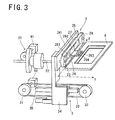
- FIG. 3 is a perspective view showing a configuration of the carrying mechanism 1.
- the carrying mechanism 1 comprises the placing table 4 on which the fluid vessel A is placed, an X-axis drive mechanism 2 for moving the placing table 4 in an X-axis direction, a Y-axis drive mechanism 3 for moving the placing table 4 in a Y-axis direction, an X-axis motor 91 driving the X-axis drive mechanism 2, and a Y-axis motor 92 driving the Y-axis drive mechanism 3.
- the X-axis direction and the Y-axis direction are two directions perpendicular to each other within a horizontal plane.
- the Y-axis drive mechanism 3 comprises a pair of pulleys 31, 32, a timing belt 33, a Y-axis slide body 34 having an inverted L-shape, and a guiding member 35, as shown in FIG. 3 .
- One pulley 31 of the pair of pulleys 31, 32 is fixed to a rotation axis of the Y-axis motor 92, and the one pulley 31 rotates around the rotation axis of the Y-axis motor 92 in accordance with rotation of the Y-axis motor 92.
- the other pulley 32 is rotatably arranged at a position displaced from the position of the one pulley 31 in the Y-axis direction.
- the timing belt 33 is entrained about the pair of pulleys 31, 32.
- the Y-axis slide body 34 is coupled to the timing belt 33 at a position between the pair of pulleys 31, 32, and an upper side part 341 of the Y-axis slide body 34 is located along the x-axis direction in a space where the placing table 4 is arranged.
- the Y-axis slide body 34 is slidably coupled to the guiding member 35, and therefore, a path on which the Y-axis slide body 34 can move is defined along the Y-axis direction.
- the timing belt 33 When the one pulley 31 rotates, the timing belt 33 thereby rotates. At this time, a part of the timing belt 33 which is located between the pair of pulleys 31, 32 moves along the Y-axis direction, and therefore, rotational motion of the one pulley 31 is converted into translational motion in the Y-axis direction by the timing belt 33.
- rotational force of the Y-axis motor 92 is converted into translational force in the Y-axis direction by the Y-axis drive mechanism 3 to be given to the Y-axis slide body 34.
- the Y-axis slide body 34 moves along the Y-axis direction.
- the X-axis drive mechanism 2 comprises a gear mechanism 21, a shaft 22 extending in the Y-axis direction, a pair of pulleys 23, 24, a timing belt 25, an X-axis slide body 26, and a guiding member 27.
- the gear mechanism 21 converts rotational force of the X-axis motor 91 into rotational force around a center axis of the shaft 22 to give the converted rotational force to the shaft 22.
- the shaft 22 is rotatably supported on the upper side part 341 of the Y-axis slide body 34 of the Y-axis drive mechanism 3, and is rotated around the center axis by the rotational force given by the gear mechanism 21.
- the shaft 22 is slidable with respect to the gear mechanism 21.
- One pulley 23 of the pair of pulleys 23, 24 is fixed to one end of the shaft 22, and the one pulley 23 rotates around the axis shared with the shaft 22 in accordance with rotation of the shaft 22.
- the other pulley 24 is rotatably attached to the upper side part 341 of the Y-axis slide body 34 at a position displaced from the position of the one pulley 23 in the x-axis direction.
- the timing belt 25 is entrained about the pair of pulleys 23, 24.
- the X-axis slide body 26 is coupled to the timing belt 25 at a position between the pair of pulleys 23, 24.
- the X-axis slide body 26 comprises a sliding part 261 and an L-shaped section 262 fixed to a front surface of the sliding part 261.
- the sliding part 261 is slidably engaged with the guiding member 27, and therefore, a path on which the sliding part 261 can move is defined along the X-axis direction.
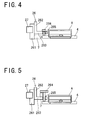
- FIG. 4 is a vertical cross-sectional view showing attachment of the placing table 4 and arrangement of the weight sensor 7.
- the placing table 4 is coupled to a lower side part 263 of the L-shaped section 262 of the X-axis slide body 26 by a coupling member 264 having a T-shape.
- the lower side part 263 of the L-shaped section 262 is provided with a through-hole 265.
- a leg part of the coupling member 264 passes through the through-hole 265, while a head part of the coupling member 264 abuts against a top surface of the lower side part 263 of the L-shaped section 262.
- the placing table 4 is fixed to a bottom end part of the leg part of the coupling member 264.
- the timing belt 25 When the one pulley 23 of the pair of pulleys 23, 24 rotates, the timing belt 25 thereby rotates. At this time, a part of the timing belt 25 which is located between the pair of pulleys 23, 24 moves along the X-axis direction, and therefore, rotational motion of the one pulley 23 is converted into translational motion in the X-axis direction by the timing belt 25.
- rotational force of the X-axis motor 91 is converted into translational force in the X-axis direction by the X-axis drive mechanism 2 to be given to the X-axis slide body 26.
- the X-axis slide body 26 moves along the X-axis direction.
- the placing table 4 coupled to the X-axis slide body 26 is moved along the X-axis direction by rotation of the X-axis motor 91, and is moved along the Y-axis direction by rotation of the Y-axis motor 92 in the X-Y plane comprising the X-axis and the Y-axis.
- the weight sensor 7 comprises a strain gauge load cell, and is fixed to the front surface of the sliding part 261 of the X-axis slide body 26 so that an end of the weight sensor 7 is in contact with a side surface of the placing table 4 as shown in FIG. 4 .
- a slight gap is defined between an inner circumferential surface of the through-hole 265 and an outer circumferential surface of the leg part of the coupling member 264, so that when the fluid vessel A is placed on the placing table 4, a power in accordance with a weight of the fluid vessel A acts on the end of the weight sensor 7 with the head part of the coupling member 264 being a fulcrum. The weight of the fluid vessel A is thereby measured by the weight sensor 7.
- the weight sensor 7 may be fixed to a top surface of the lower side part 263 of the L-shaped section 262 so that the end of the weight sensor 7 is in contact with a lower surface of the head part of the coupling member 264.
- a total weight of the fluid vessel A and the liquid contained in the fluid vessel A is measured by the weight sensor 7, and then the weight of the fluid vessel A which is empty is reduced from the measured total weight.
- the weight sensor 7 forms a detection device detecting depth information (the total weight of the fluid vessel A and the liquid) changing in accordance with a depth H of the liquid in the fluid vessel A.
- the control device 8 is connected to the carrying mechanism 1 and the weight sensor 7 described above, while an information inputting unit 9 such as a personal computer, a key board, a touch panel, a mouse or the like is connected to the control device 8.
- the control device 8 comprises an information acquisition unit 81, an information read out unit 82, a storage unit 83, a depth calculation unit 84, a computing unit 85, a pattern preparing unit 86, and a carry command unit 87.
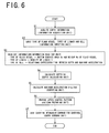
- the control device 8 controls the carrying mechanism 1 in accordance with a flow chart shown in FIG. 6 .
- the control device 8 may be configured by a CPU (Central Processing Unit), a dedicated LSI (Large Scale Integration), a personal computer and the like.
- the control device 8 comprising the information acquisition unit 81, the computing unit 85, and the carry command unit 87 may be formed by the personal computer. Also, functions of each unit 81 to 87 of the control device 8 can be performed by execution of a program.
- a bottom surface area Sa and a weight Wa of the fluid vessel A associated with a type of the fluid vessel A
- a density C of the liquid associated with a type of the liquid
- a relational expression F(H) between the depth H of the liquid and a maximum acceleration Amax associated with the type of the cell as shown in FIG. 7 .
- the maximum acceleration is a maximum value of the acceleration which can be given to the fluid vessel A during carrying the fluid vessel A.
- the maximum acceleration is a maximum value of the acceleration at which the cell adhering to a bottom surface of the fluid vessel A is hardly removed from the bottom surface during carrying the fluid vessel A.
- An adhesive force of the cell to the bottom surface varies depending on the type of the cell. Therefore, even if the depth of the liquid is the same, when the type of the cell is different, the maximum acceleration is also different. In particular, as shown in FIG.
- the liquid in the fluid vessel A has a wave and the liquid in the fluid vessel A vibrates.
- the larger the depth of the liquid the smaller the vibration of the liquid in vicinity of the bottom surface of the fluid vessel A where the cell adheres becomes, while the smaller the depth of the liquid is, the larger the vibration of the liquid in vicinity of the bottom surface of the fluid vessel A where the cell adheres becomes. Therefore, as shown in FIG. 7 , the larger the depth of the liquid is, the larger the maximum acceleration becomes, while the smaller the depth of the liquid is, the smaller the maximum acceleration becomes.
- FIG. 7 shows a case where the relational expression F(H) is a linear function
- the relational expression F(H) is not limited to this, and may be a quadratic function or function of any higher order, for example.
- step S1 the control device 8 uses the information acquisition unit 81 as shown in FIG. 2 to acquire the total weight of the fluid vessel A and the liquid as depth information Id from the weight sensor 7.
- the depth information Id (the total weight of the fluid vessel A and the liquid) acquired from the weight sensor 7 is given to the depth calculation unit 84 of the control device 8.
- step S2 a type of the fluid vessel A and types of the liquid and the cell contained in the fluid vessel A are inputted by the information inputting unit 9.
- Information Ii inputted in the control device 8 by the information inputting unit 9 is given to the information read out unit 82 of the control device 8 as shown in FIG. 2 .
- the information inputting unit 9 is the personal computer
- the information Ii is given to the control device 8 by means of character entry from the personal computer.
- the information read out unit 82 may be a reading unit reading a QR (Quick Response) code or an RF-ID (Radio Frequency Identification).
- QR Quick Response
- RF-ID Radio Frequency Identification
- the QR code and the RF-ID are attached to the fluid vessel A, for example.
- a camera is used as the reading unit when the QR code is read, and a reader antenna is used as the reading unit when the RF-ID is read.
- step S3 the control device 8 uses the information read out unit 82 as shown in FIG. 2 to read out from the storage unit 83 the bottom surface area Sa and the weight Wa of the fluid vessel A associated with the type of the fluid vessel A inputted in step S2, as well as density C of the liquid associated with the type of the liquid inputted in step S2.
- the bottom surface area Sa, weight Wa of the fluid vessel A, and the density C of the liquid read out from the storage unit 83 are given to the depth calculation unit 84 of the control device 8.
- the control device 8 uses the information reading unit 82 to read out from the storage unit 83 the relational expression F(H) between the depth H of the liquid and the maximum acceleration Amax associated with the type of the cell inputted in step S2.
- the relational expression F(H) read out from the storage unit 83 is given to the computing unit 85 of the control device 8.
- step S4 the control device 8 uses the depth calculation unit 84 as shown in FIG. 2 to calculate a depth Hd of the liquid based on the depth information Id (the total weight of the fluid vessel A and the liquid) acquired in step S1, and the bottom surface area Sa and the weight Wa of the fluid vessel A and the density C of the liquid read out in step S3.
- the depth calculation unit 84 of the control device 8 calculates the weight of the liquid by reducing the weight Wa of the fluid vessel A from the total weight of the fluid vessel A and the liquid which is the depth information Id, then calculates a volume of the liquid by dividing the calculated weight of the liquid by the density C of the liquid, and then, calculates the depth Hd of the liquid by dividing the calculated volume of the liquid by the bottom surface area Sa of the fluid vessel A.
- the depth Hd of the liquid calculated by the depth calculation unit 84 is given to the computing unit 85.
- step S5 the control device 8 uses the computing unit 85 to calculates the maximum acceleration Amax(Hd) based on the relational expression F(H) read out in step S3 and the depth Hd of the liquid calculated in step S4.
- the computing unit 85 of the control device 8 calculates the maximum acceleration Amax(Hd) corresponding to the depth Hd of the liquid calculated in step S4 from the relational expression F(H) between the depth H of the liquid and the maximum acceleration Amax shown in FIG. 7 .
- the depth H of the liquid and the maximum acceleration Amax have a relation in which the larger the depth H of the liquid is, the larger the maximum acceleration Amax becomes, while the smaller the depth H of the liquid is, the smaller the maximum acceleration Amax becomes.
- the maximum acceleration Amax(Hd) is calculated to be 12 mm/s 2
- the maximum acceleration Amax(Hd) is calculated to be 24 mm/s 2 .
- the maximum acceleration Amax(Hd) calculated by the computing unit 85 is given to the pattern preparing unit 86 as shown in FIG. 2 .
- step S6 the control device 8 uses the pattern preparing unit 86 to prepare a speed control pattern based on the maximum acceleration Amax(Hd) calculated in step S5.
- the speed control pattern is a function of time representing a change in velocity of the fluid vessel A, which is to be controlled.
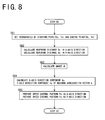
- FIG. 8 is a flow chart showing control executed in step S6.
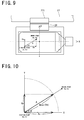
- FIG. 9 is a plane view showing a starting point (Xs, Ys) and an ending point (Xe, Ye) of movement of the fluid vessel A.
- FIG. 10 is a view showing a maximum acceleration vector A from the starting point (Xs, Ys) to the ending point (Xe, Ye) having a magnitude of the maximum acceleration Amax(Hd), and an X-axis direction component Ax and Y-axis direction component Ay thereof.
- step S61 the starting point (Xs, Ys) and the ending point (Xe, Ye) (see FIG. 9 ) for moving the fluid vessel A are inputted by the information inputting unit 9.
- the starting point (Xs, Ys) and the ending point (Xe, Ye) inputted by the information inputting unit 9 are given to the pattern preparing unit 86 of the control device 8.
- step S62 the pattern preparing unit 86 uses the starting point (Xs, Ys) and the ending point (Xe, Ye) given thereto to calculate (Xe-Xs), thereby calculating a distance Dx which the fluid vessel A moves along the X-axis direction (movement distance in the X-axis direction), while calculate (Ye-Ys), thereby calculating a distance Dy which the fluid vessel A moves along the Y-axis direction (movement distance in the Y-axis direction).
- ⁇ tan ⁇ 1 Dy / Dx
- step S64 the pattern preparing unit 86 calculates the X-axis direction component Ax and the Y-axis direction component Ay (see FIG. 10 ) of the maximum acceleration vector A from the starting point (Xs, Ys) to the ending point (Xe, Ye) having a magnitude of the maximum acceleration Amax(Hd) based on the maximum acceleration Amax(Hd) calculated in step S5 and the angle ⁇ calculated in step S63 by a formula (2).
- Ax Amax Hd cos ⁇
- Ay Amax Hd sin ⁇
- FIG. 11a and FIG. 11b are views showing in graphs a speed control pattern Px in the X-axis direction and a speed control pattern Py in the Y-axis direction for moving the fluid vessel A from the starting point (Xs, Ys) to the ending point (Xe, Ye).
- step S65 as shown in FIGS.
- the pattern preparing unit 86 prepares the speed control pattern Px in the X-axis direction and the speed control pattern Py in the Y-axis direction for moving the fluid vessel A from the starting point (Xs, Ys) to the ending point (Xe, Ye) based on the movement distances Dx, Dy in the X-axis direction and the Y-axis direction calculated in step S62 and the X-axis direction component Ax and the Y-axis direction component Ay of the maximum acceleration vector A calculated in step S64.
- the FIGS. 11a and 11b show the case where the speed control patterns Px, Py have a trapezoidal shape.
- a velocity vector of the fluid vessel A is determined by synthesis of a velocity component in the X-axis direction and a velocity component in the Y-axis direction. Therefore, if the speed control pattern Px in the X-axis direction and the speed control pattern Py in the Y-axis direction are prepared separately and independently, it is possible that the acceleration of the fluid vessel A during moving from the starting point (Xs, Ys) to the ending point (Xe, Ye) exceeds the maximum acceleration Amax(Hd).
- the speed control patterns Px, Py are prepared based on the X-axis direction component Ax and the Y-axis direction component Ay of the maximum acceleration vector A, in a manner described below.
- the speed control pattern Px in the X-axis direction is prepared so that the maximum value Gx of the inclination thereof is not greater than the X-axis direction component Ax of the maximum acceleration vector A
- the speed control pattern Py in the Y-axis direction is prepared so that a maximum value Gy of the inclination thereof is not greater than the Y-axis direction component Ay of the maximum acceleration vector A.
- the speed control pattern Px in the X-axis direction is prepared so that a value obtained by integrating a function representing the speed control pattern Px by time matches the movement distance Dx in the X-axis direction
- the speed control pattern Py in the Y-axis direction is prepared so that a value obtained by integrating a function representing the speed control pattern Py by time matches the movement distance Dy in the Y-axis direction.
- the speed control pattern Px in the X-axis direction and the speed control pattern Py in the Y-axis direction prepared by the pattern preparing unit 86 are given to the carry command unit 87 as shown in FIG. 2 .
- step S7 the carry command unit 87 gives a command to the carrying mechanism 1 based on the speed control pattern Px in the X-axis direction and the speed control pattern Py in the Y-axis direction prepared in step S6.
- the fluid vessel A moves in the X-axis direction in accordance with the speed control pattern Px in the X-axis direction prepared in step S6, while moves in the Y-axis direction in accordance with the speed control pattern Py in the Y-axis direction prepared in step S6.
- the speed control pattern Px in the X-axis direction is prepared so that the maximum value Gx of the inclination thereof is not greater than the X-axis direction component Ax of the maximum acceleration vector A, while the speed control pattern Py in the Y-axis direction is prepared so that the maximum value Gy of the inclination thereof is not greater than the Y-axis direction component Ay of the maximum acceleration vector A. Therefore, a maximum value G of the acceleration in the direction from the starting point (Xs, Ys) to the ending point (Xe, Ye) does not exceed the maximum acceleration Amax(Hd) calculated in step S5.
- the fluid vessel A is carried from the starting point (Xs, Ys) which is the one point to the ending point (Xe, Ye) which is the other point at an acceleration not greater than the maximum acceleration Amax(Hd).
- the carrying mechanism 1 is controlled so that the acceleration of the fluid vessel A during carrying the fluid vessel A is not greater than the maximum acceleration Amax(Hd). Therefore, even in the case of carrying the fluid vessel A containing the liquid the depth Hd of which is small, the cell is hardly removed from the bottom surface of the fluid vessel A.
- the maximum acceleration Amax(Hd) calculated in step S5 is large based on the relational expression F(H) between the depth H of the liquid and the maximum acceleration Amax shown in FIG. 7 . Therefore, the change in the velocity of the fluid vessel A during carrying the fluid vessel A is drastic as shown in FIG. 13a , and the movement time T of the fluid vessel A from the starting point (Xs, Ys) to the ending point (Xe, Ye) is shortened.
- the change in the velocity of the fluid vessel A during carrying the fluid vessel A is gradual as shown in FIG. 13b , and the movement time T of the fluid vessel A from the starting point (Xs, Ys) to the ending point (Xe, Ye) is extended.
- the weight sensor 7 may be replaced with an imaging device.
- the depth calculation unit 84 is replaced with an image processing unit.
- the imaging device images the liquid in the fluid vessel A from a side, whereby an image showing the bottom surface of the fluid vessel A and a surface of the liquid is used as the depth information.
- the image which is the depth information is subjected to image processing by the image processing unit, whereby the depth Hd of the liquid is derived based on the bottom surface of the fluid vessel A and the surface of the liquid.
- step S1 the depth information (the image) is acquired from the imaging device described above. And then in step S4, the image acquired in step S1 is subjected to the image processing by the image processing unit, whereby the depth Hd of the liquid is derived.
- the liquid may be stained to red with phenol red or the like, for example.
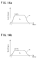
- FIGS. 14 are views showing in graphs other examples of the speed control pattern Px in the X-axis direction and the speed control pattern Py in the Y-axis direction which are formed by the pattern preparing unit 86 of the control device 8.
- the speed control pattern Px in the X-axis direction and the speed control pattern Py in the Y-axis direction have the trapezoidal shape. However, they may have an S-shape as shown in FIGS. 14a and 14b .
- the speed control pattern Px in the X-axis direction is prepared so that an inclination Gx at the inflection point is not greater than the X-axis direction component Ax of the maximum acceleration vector A as shown in FIG. 14a
- the speed control pattern Py in the Y-axis direction is prepared so that an inclination Gy at the inflection point is not greater than the Y-axis direction component Ay of the maximum acceleration vector A as shown in FIG. 14b .
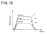
- step S7 the carry command unit 87 gives a command to the carrying mechanism 1 based on the speed control patterns Px, Py shown in FIGS. 14a and 14b , whereby the velocity of the fluid vessel A during carrying the fluid vessel A changes in the S-shape in accordance with a graph P shown in FIG, 15 .
- the speed control pattern Px in the X-axis direction is prepared so that the maximum value Gx of the inclination thereof is not greater than the X-axis direction component Ax of the maximum acceleration vector A
- the speed control pattern Py in the Y-axis direction is prepared so that the maximum value Gy of the inclination thereof is not greater than the Y-axis direction component Ay of the maximum acceleration vector A. Therefore, the maximum value G of the acceleration in the direction from the starting point (Xs, Ys) to the ending point (Xe, Ye) does not exceed the maximum acceleration Amax(Hd) calculated in step S5. Accordingly, even in the case where the fluid vessel A is carried, the cell is hardly removed from the bottom surface of the fluid vessel A.
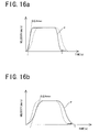
- the maximum acceleration Amax(Hd) calculated in step S5 is large based on the relational expression F(H) between the depth H of the liquid and the maximum acceleration Amax shown in FIG. 7 . Therefore, the change in the velocity of the fluid vessel A is drastic as shown in FIG. 16a , and the movement time T of the fluid vessel A from the starting point (Xs, Ys) to the ending point (Xe, Ye) is shortened. Accordingly, it is possible to carry the fluid vessel A quickly.
- the present invention is not limited to the foregoing embodiment in construction but can be modified variously within the technical range set forth in the appended claims.
- the relational expression F(H) between the depth H of the liquid and the maximum acceleration Amax is not limited to the one passing through the original as shown in FIG. 7 ., but may be one with a y-intercept which is other than zero.
- the depth information Id is detected by the detection device of the weight sensor 7 or the imaging device, and the depth information Id is acquired from the detection device by the information acquisition unit 81 of the control device 8.
- the depth information Id may be detected by a device other than the carrying device 100, and then given to the control device 8 by the information inputting unit 9, for example.
- the depth Hd of the liquid is calculated from the depth information Id by the depth calculation unit 84, and the maximum acceleration Amax(Hd) is calculated from the depth Hd of the liquid by the computing unit 85.
- the maximum acceleration Amax(Hd) may be directly calculated from the depth information Id by the computing unit 85 without providing the depth calculation unit 84, for example.
- the preparation of the speed control patterns Px, Py by the pattern preparing unit 86 described above may be executed by the computing unit 85.
- the shape of the speed control patterns Px, Py in the X-axis direction and the Y-axis direction is not limited to the trapezoidal shape or the S-shape, but may be other shapes.
- the detection device for detecting the depth information Id is not limited to the weight sensor or the imaging device described above.
- the carrying device 100 described above can be applied not only to the observation unit but also various kinds of devices.
Landscapes
- Engineering & Computer Science (AREA)
- Human Computer Interaction (AREA)
- Manufacturing & Machinery (AREA)
- Physics & Mathematics (AREA)
- General Physics & Mathematics (AREA)
- Automation & Control Theory (AREA)
- Automatic Analysis And Handling Materials Therefor (AREA)
- Apparatus Associated With Microorganisms And Enzymes (AREA)
- Measuring Or Testing Involving Enzymes Or Micro-Organisms (AREA)
- Measurement Of Levels Of Liquids Or Fluent Solid Materials (AREA)
Abstract
Description
- The present invention relates to a carrying device for carrying a fluid vessel containing a liquid such as culture fluid or the like, and to a control device and a program associated with the carrying device.
- Conventionally, some culture apparatuses such as an incubator or the like include a carrying device for carrying a fluid vessel stored in the culture apparatus. The incubator controls a culture environment in which cells are cultured. In particular, the culture apparatus is provided with a stocker which can contain a plurality of fluid vessels, a carrying device which can carry the fluid vessel both in a horizontal direction and in a vertical direction, and an observation device for observing a sample in the fluid vessel. It is possible that the carrying device takes out the fluid vessel from the stocker and carries the fluid vessel to a position where an observation is executed by the observation device. Also, it is possible that the carrying device returns the fluid vessel into the stocker after completion of the observation.
- Also, conventionally, a cell is contained in the fluid vessel along with the liquid such as culture fluid or the like for culturing the cell by the culture apparatus and observing the cultured cell. Methods of observing the cell in the liquid include a method of setting a coordinate system in the fluid vessel, specifying a position of the cell in the fluid vessel by means of a position in the coordinate system, and repeatedly observing the cell existing at the same position in the coordinate system. With this method, even in the case where the fluid vessel is once returned into the stocker, the same cell can be observed again in a next observation.
- In the case where the fluid vessel is carried in the horizontal direction by the carrying device, the liquid in the fluid vessel has a wave in accordance with acceleration of the fluid vessel, and the liquid in the fluid vessel vibrates. Therefore, to the cell floating in the liquid, since it moves from its original position during carrying the fluid vessel, it was difficult to adopt the observation method described above.
- In contrast, to the cell adhering to a bottom surface of the fluid vessel, since it hardly moves from its original position even during carrying the fluid vessel, it was easier to adopt the observation method described above.
- However, the smaller a depth of the liquid is, the larger the vibration of the liquid in vicinity of the bottom surface of the fluid vessel where the cell adheres becomes. Therefore, in the case where the fluid vessel is carried at a uniform acceleration regardless of the depth of the liquid in the fluid vessel, in the fluid vessel containing the liquid a depth of which is small, the vibration of the liquid in vicinity of the bottom surface is large, and it is possible that the cell adhering to the bottom surface is removed therefrom due to the vibration.
- If the cell is removed from the bottom surface, the cell is displaced from a position where the cell was adhering, and therefore, it is difficult to repeatedly observe the same cell by the observation method described above. Also, if the cell is removed from the bottom surface, it is possible that culture of the cell is prevented.
- In view of above described problem, an object of the present invention is to provide a carrying device capable of carrying a fluid vessel quickly while inhibiting vibration of a liquid existing in vicinity of a bottom surface of the fluid vessel.
- A first carrying device according to the present invention comprises a carrying mechanism carrying a fluid vessel containing a liquid, a detection device detecting depth information changing in accordance with a depth of the liquid in the fluid vessel, and a control device controlling the carrying mechanism. The control device comprises an information acquisition unit acquiring the depth information detected by the detection device, a computing unit calculating a maximum value of an acceleration which can be given to the fluid vessel during carrying the fluid vessel based on the depth information acquired by the information acquisition unit, and a carry command unit giving the carrying mechanism a command for carrying the fluid vessel at an acceleration of not greater than the maximum value of the acceleration, the computing unit calculates a greater value as the maximum value of the acceleration as the depth of the liquid in the fluid vessel increases, and calculates a smaller value as the maximum value of the acceleration as the depth of the liquid in the fluid vessel decreases.
- According to the first carrying device described above, calculated in accordance with the depth of the liquid in the fluid vessel is the maximum value of the acceleration at which vibration of the liquid existing in vicinity of a bottom surface of the fluid vessel can be inhibited. The carrying mechanism is controlled by the control device so that the acceleration of the fluid vessel during carrying the fluid vessel is not greater than the maximum value, and therefore, the liquid existing in vicinity of the bottom surface of the fluid vessel hardly vibrates even in the case of carrying the fluid vessel containing the liquid the depth of which is small.
- In the case where the acceleration of the fluid vessel during carrying the fluid vessel is equalized under control of the control device with the maximum value of the acceleration at which the vibration of the liquid can be inhibited, movement time of the fluid vessel is shortened, whereby it is possible to carry the fluid vessel quickly.
- Further, a configuration in which the maximum value of the acceleration calculated by the computing unit of the control device becomes larger as the depth of the liquid in the fluid vessel becomes larger is based on a phenomenon that the larger the depth of the liquid in the fluid vessel is, the more hardly the vibration of the liquid existing in vicinity of the bottom surface of the fluid vessel occurs. With this configuration, it is possible to carry the fluid vessel more quickly as the depth of the liquid in the fluid vessel becomes larger.
- A second carrying device according to the present invention is the first carrying device described above,
wherein the detection device comprises a weight sensor, and a weight of the liquid measured by the weight sensor is detected as the depth information. With the second carrying device, the larger the depth of the liquid is, the larger the weight of the liquid is, while the smaller the depth of the liquid is, the smaller the weight of the liquid is. Therefore, by using the weight of the liquid as the depth information, it is possible to carry the fluid vessel in accordance with the depth of the liquid. - A third carrying device according to the present invention is the first carrying device described above,
wherein the detection device comprises an imaging device, and the imaging device images the liquid in the fluid vessel from a side, whereby an image showing the bottom surface of the fluid vessel and a surface of the liquid is detected as the depth information. With the third carrying device, the larger the depth of the liquid is, the larger a distance between the bottom surface of the fluid vessel and the surface of the liquid is, while the smaller the depth of the liquid is, the smaller a distance between the bottom surface of the fluid vessel and the surface of the liquid is. Therefore, by using the image as the depth information, it is possible to carry the fluid vessel in accordance with the depth of the liquid. - A fourth carrying device according to the present invention is any of the first to third carrying devices described above, wherein the carrying mechanism carries the fluid vessel along a plane comprising a first axis and a second axis intersecting the first axis. In the case of carrying the fluid vessel between two points on the plane from one point to the other point, based on a first axis direction component and a second axis direction component of an acceleration vector from the one point to the other point having a magnitude of the maximum value of the acceleration, the carry command unit of the control device gives the carrying mechanism a command for carrying the fluid vessel in a first axis direction at the acceleration of not greater than the first axis direction component, while carrying the fluid vessel in a second axis direction at the acceleration of not greater than the second axis direction component.
- With the fourth carrying device described above, the fluid vessel moves in the plane comprising the first axis and the second axis. In the case where the fluid vessel moves between two points on the plane from one point to the other point, under control of the control device, the fluid vessel moves in the first axis direction at the acceleration of not greater than the first axis direction component of the acceleration vector, while the fluid vessel moves in the second axis direction at the acceleration of not greater than the second axis direction component of the acceleration vector. Therefore, a maximum value of the acceleration at which the fluid vessel moves from one point to the other point does not exceed the maximum value of the acceleration calculated by the computing unit.
- Accordingly, even in the case where the fluid vessel containing the liquid the depth of which is small is carried in the plane by the carrying mechanism, the liquid existing in vicinity of the bottom surface of the fluid vessel hardly vibrates.
- A control device according to the present invention is a control device for controlling a carrying mechanism carrying a fluid vessel containing a liquid, and comprises an information acquisition unit acquiring a depth information changing in accordance with a depth of the liquid in the fluid vessel, a computing unit calculating a maximum value of an acceleration which can be given to the fluid vessel during carrying the fluid vessel based on the depth information acquired by the information acquisition unit, and a carry command unit giving the carrying mechanism a command for carrying the fluid vessel at an acceleration of not greater than the maximum value of the acceleration. The computing unit calculates a greater value as the maximum value of the acceleration as the depth of the liquid in the fluid vessel increases, and calculates a smaller value as the maximum value of the acceleration as the depth of the liquid in the fluid vessel decreases.
- A program according to the present invention is a program for controlling a carrying mechanism carrying a fluid vessel containing a liquid. The program makes a computer acquire depth information changing in accordance with a depth of the liquid in the fluid vessel, calculate a maximum value of an acceleration which can be given to the fluid vessel during carrying the fluid vessel based on the depth information acquired, and give the carrying mechanism a command for carrying the fluid vessel at an acceleration of not greater than the maximum value of the acceleration. The computer calculates a greater value as the maximum value of the acceleration as the depth of the liquid in the fluid vessel increases, and calculates a smaller value as the maximum value of the acceleration as the depth of the liquid in the fluid vessel decreases.
-
-
FIG. 1 is a perspective view of an observation unit provided with a carrying device according to an embodiment of the present invention; -
FIG. 2 is a block diagram showing a configuration of the carrying device; -
FIG. 3 is a perspective view of a carrying mechanism provided to the carrying device; -
FIG. 4 is a vertical cross-sectional view showing an arrangement of a weight sensor provided to the carrying device; -
FIG. 5 is a vertical cross-sectional view showing another arrangement of the weight sensor; -
FIG. 6 is a flow chart for controlling the carrying mechanism provided to the carrying device; -
FIG. 7 is a view showing in a graph a relation between a depth of a liquid and a maximum acceleration for each cell type; -
FIG. 8 is a flow chart showing control executed by a pattern preparing unit of a control device provided to the carrying device; -
FIG. 9 is a plane view showing a starting point and an ending point of movement of a fluid vessel; -
FIG. 10 is a view showing a maximum acceleration vector and an X-axis direction component and Y-axis direction component thereof; -
FIG. 11a is a view showing in a graph a speed control pattern in an X-axis direction; -
FIG. 11b is a view showing in a graph a speed control pattern in a Y-axis direction; -
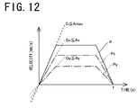
FIG. 12 is a view showing in a graph a change in velocity of the fluid vessel in a direction from the starting point to the ending point; -
FIG. 13a is a view showing in a graph a change in velocity of the fluid vessel in the case where the depth of the liquid is large; -
FIG. 13b is a view showing in a graph a change in velocity of the fluid vessel in the case where the depth of the liquid is small; -
FIG. 14a is a view showing in a graph another example of the speed control pattern in the X-axis direction; -
FIG. 14b is a view showing in a graph another example of the speed control pattern in the Y-axis direction; -
FIG. 15 is a view showing in a graph a change in velocity of the fluid vessel in the direction from the starting point to the ending point; -
FIG. 16a is a view showing in a graph a change in velocity of the fluid vessel in the case where the depth of the liquid is large; and -
FIG. 16b is a view showing in a graph a change in velocity of the fluid vessel in the case where the depth of the liquid is small. - In the case where a fluid vessel moves between two points on a plane from one point to the other point, if an acceleration of the fluid vessel in a direction from the one point to the other point is large, vibration of a liquid in vicinity of a bottom surface of the fluid vessel is large. Therefore, it is possible that a cell adhering to the bottom surface of the fluid vessel is removed therefrom due to the vibration. In view of this, it is necessary to control the acceleration of the fluid vessel in the direction from the one point to the other point to not greater than a maximum value of the acceleration at which the cell is hardly removed from the bottom surface of the fluid vessel.
- In a preferred embodiment discussed in detail below with reference to drawings, a carrying device according to the present invention is provided to an observation unit.
-
FIG. 1 is a perspective view of an observation unit provided with a carryingdevice 100 according to the embodiment of the present invention. As shown inFIG. 1 , the observation unit is provided with anobservation device 5 and an illuminatingdevice 6 in addition to the carryingdevice 100 according to the embodiment of the present invention. - The
observation device 5 is a phase-contrast microscope and comprises anobjective lens 51 forming an enlarged image of a sample which is to be observed, areflective mirror 52 guiding the enlarged image formed by theobjective lens 51 to azoom lens 53, thezoom lens 53 further enlarging the enlarged image of the sample, and a CCD (Charge Coupled Device)camera 54 imaging an observation image enlarged by thezoom lens 53. - The illuminating
device 6 comprises an LED (Light Emitting Diode) 61 emitting light and areflective mirror 62 reflecting light emitted by theLED 61 vertically downward. The illuminatingdevice 6 is arranged above theobservation device 5, and thereflective mirror 62 is arranged so that the reflected light enters theobjective lens 51 of theobservation device 5. - A position through which the light reflected by the
reflective mirror 62 passes in an X-Y plane in which a placing table 4 can move is an observation point M where the sample is observed by theobservation device 5. -
FIG. 2 is a block diagram showing a configuration of the carryingdevice 100. As shown inFIG. 2 , the carryingdevice 100 comprises acarrying mechanism 1 for carrying a fluid vessel A, aweight sensor 7, and acontrol device 8 controlling thecarrying mechanism 1. The fluid vessel A contains the sample such as a cell or the like as well as a liquid such as culture fluid or the like. -
FIG. 3 is a perspective view showing a configuration of thecarrying mechanism 1. As shown inFIG. 3 , the carryingmechanism 1 comprises the placing table 4 on which the fluid vessel A is placed, anX-axis drive mechanism 2 for moving the placing table 4 in an X-axis direction, a Y-axis drive mechanism 3 for moving the placing table 4 in a Y-axis direction, anX-axis motor 91 driving theX-axis drive mechanism 2, and a Y-axis motor 92 driving the Y-axis drive mechanism 3. The X-axis direction and the Y-axis direction are two directions perpendicular to each other within a horizontal plane. - The Y-
axis drive mechanism 3 comprises a pair ofpulleys timing belt 33, a Y-axis slide body 34 having an inverted L-shape, and a guidingmember 35, as shown inFIG. 3 . Onepulley 31 of the pair ofpulleys axis motor 92, and the onepulley 31 rotates around the rotation axis of the Y-axis motor 92 in accordance with rotation of the Y-axis motor 92. - The
other pulley 32 is rotatably arranged at a position displaced from the position of the onepulley 31 in the Y-axis direction. - The
timing belt 33 is entrained about the pair ofpulleys axis slide body 34 is coupled to thetiming belt 33 at a position between the pair ofpulleys upper side part 341 of the Y-axis slide body 34 is located along the x-axis direction in a space where the placing table 4 is arranged. Also, the Y-axis slide body 34 is slidably coupled to the guidingmember 35, and therefore, a path on which the Y-axis slide body 34 can move is defined along the Y-axis direction. - When the one
pulley 31 rotates, thetiming belt 33 thereby rotates. At this time, a part of thetiming belt 33 which is located between the pair ofpulleys pulley 31 is converted into translational motion in the Y-axis direction by thetiming belt 33. - Accordingly, rotational force of the Y-
axis motor 92 is converted into translational force in the Y-axis direction by the Y-axis drive mechanism 3 to be given to the Y-axis slide body 34. As a result, the Y-axis slide body 34 moves along the Y-axis direction. - As shown in
FIG. 3 , theX-axis drive mechanism 2 comprises agear mechanism 21, ashaft 22 extending in the Y-axis direction, a pair ofpulleys timing belt 25, anX-axis slide body 26, and a guidingmember 27. - The
gear mechanism 21 converts rotational force of theX-axis motor 91 into rotational force around a center axis of theshaft 22 to give the converted rotational force to theshaft 22. Theshaft 22 is rotatably supported on theupper side part 341 of the Y-axis slide body 34 of the Y-axis drive mechanism 3, and is rotated around the center axis by the rotational force given by thegear mechanism 21. Theshaft 22 is slidable with respect to thegear mechanism 21. - One
pulley 23 of the pair ofpulleys shaft 22, and the onepulley 23 rotates around the axis shared with theshaft 22 in accordance with rotation of theshaft 22. - The
other pulley 24 is rotatably attached to theupper side part 341 of the Y-axis slide body 34 at a position displaced from the position of the onepulley 23 in the x-axis direction. - The
timing belt 25 is entrained about the pair ofpulleys X-axis slide body 26 is coupled to thetiming belt 25 at a position between the pair ofpulleys - The
X-axis slide body 26 comprises a slidingpart 261 and an L-shapedsection 262 fixed to a front surface of the slidingpart 261. The slidingpart 261 is slidably engaged with the guidingmember 27, and therefore, a path on which the slidingpart 261 can move is defined along the X-axis direction. -
FIG. 4 is a vertical cross-sectional view showing attachment of the placing table 4 and arrangement of theweight sensor 7. As shown inFIG. 4 , the placing table 4 is coupled to alower side part 263 of the L-shapedsection 262 of theX-axis slide body 26 by acoupling member 264 having a T-shape. In particular, thelower side part 263 of the L-shapedsection 262 is provided with a through-hole 265. A leg part of thecoupling member 264 passes through the through-hole 265, while a head part of thecoupling member 264 abuts against a top surface of thelower side part 263 of the L-shapedsection 262. Also, the placing table 4 is fixed to a bottom end part of the leg part of thecoupling member 264. - When the one
pulley 23 of the pair ofpulleys timing belt 25 thereby rotates. At this time, a part of thetiming belt 25 which is located between the pair ofpulleys pulley 23 is converted into translational motion in the X-axis direction by thetiming belt 25. - Accordingly, rotational force of the
X-axis motor 91 is converted into translational force in the X-axis direction by theX-axis drive mechanism 2 to be given to theX-axis slide body 26. As a result, theX-axis slide body 26 moves along the X-axis direction. - Therefore, with the
carrying mechanism 1, the placing table 4 coupled to theX-axis slide body 26 is moved along the X-axis direction by rotation of theX-axis motor 91, and is moved along the Y-axis direction by rotation of the Y-axis motor 92 in the X-Y plane comprising the X-axis and the Y-axis. - The
weight sensor 7 comprises a strain gauge load cell, and is fixed to the front surface of the slidingpart 261 of theX-axis slide body 26 so that an end of theweight sensor 7 is in contact with a side surface of the placing table 4 as shown inFIG. 4 . A slight gap is defined between an inner circumferential surface of the through-hole 265 and an outer circumferential surface of the leg part of thecoupling member 264, so that when the fluid vessel A is placed on the placing table 4, a power in accordance with a weight of the fluid vessel A acts on the end of theweight sensor 7 with the head part of thecoupling member 264 being a fulcrum. The weight of the fluid vessel A is thereby measured by theweight sensor 7. - As shown in
FIG. 5 , theweight sensor 7 may be fixed to a top surface of thelower side part 263 of the L-shapedsection 262 so that the end of theweight sensor 7 is in contact with a lower surface of the head part of thecoupling member 264. - In order to acquire a weight of the liquid contained in the fluid vessel A, a total weight of the fluid vessel A and the liquid contained in the fluid vessel A is measured by the
weight sensor 7, and then the weight of the fluid vessel A which is empty is reduced from the measured total weight. - The total weight of the fluid vessel A and the liquid detected by the
weight sensor 7 changes in accordance with the depth of the liquid in the fluid vessel A. Therefore, in the carryingdevice 100 according to this embodiment, theweight sensor 7 forms a detection device detecting depth information (the total weight of the fluid vessel A and the liquid) changing in accordance with a depth H of the liquid in the fluid vessel A. - As shown in
FIG. 2 , thecontrol device 8 is connected to thecarrying mechanism 1 and theweight sensor 7 described above, while aninformation inputting unit 9 such as a personal computer, a key board, a touch panel, a mouse or the like is connected to thecontrol device 8. Thecontrol device 8 comprises aninformation acquisition unit 81, an information read outunit 82, astorage unit 83, adepth calculation unit 84, acomputing unit 85, apattern preparing unit 86, and acarry command unit 87. Thecontrol device 8 controls thecarrying mechanism 1 in accordance with a flow chart shown inFIG. 6 . - The
control device 8 may be configured by a CPU (Central Processing Unit), a dedicated LSI (Large Scale Integration), a personal computer and the like. For example, thecontrol device 8 comprising theinformation acquisition unit 81, thecomputing unit 85, and thecarry command unit 87 may be formed by the personal computer. Also, functions of eachunit 81 to 87 of thecontrol device 8 can be performed by execution of a program. - Following is an explanation of a case where a cell is contained in the fluid vessel A as the sample along with the liquid.
- In the
storage unit 83 of thecontrol device 8, stored are a bottom surface area Sa and a weight Wa of the fluid vessel A, associated with a type of the fluid vessel A; a density C of the liquid, associated with a type of the liquid; and a relational expression F(H) between the depth H of the liquid and a maximum acceleration Amax, associated with the type of the cell as shown inFIG. 7 . - Here, the maximum acceleration is a maximum value of the acceleration which can be given to the fluid vessel A during carrying the fluid vessel A. In this embodiment, the maximum acceleration is a maximum value of the acceleration at which the cell adhering to a bottom surface of the fluid vessel A is hardly removed from the bottom surface during carrying the fluid vessel A. An adhesive force of the cell to the bottom surface varies depending on the type of the cell. Therefore, even if the depth of the liquid is the same, when the type of the cell is different, the maximum acceleration is also different. In particular, as shown in
FIG. 7 , as the adhesive force of the cell becomes smaller in the order of a cell A, a cell B, and a cell C, the cell is more easily removed from the bottom surface, and therefore, an inclination of the maximum acceleration Amax to the depth H of the liquid becomes smaller. - In the case where the fluid vessel A is moved in the X-Y plane by the carrying
mechanism 1, along with acceleration of the fluid vessel A, the liquid in the fluid vessel A has a wave and the liquid in the fluid vessel A vibrates. At this time, the larger the depth of the liquid is, the smaller the vibration of the liquid in vicinity of the bottom surface of the fluid vessel A where the cell adheres becomes, while the smaller the depth of the liquid is, the larger the vibration of the liquid in vicinity of the bottom surface of the fluid vessel A where the cell adheres becomes. Therefore, as shown inFIG. 7 , the larger the depth of the liquid is, the larger the maximum acceleration becomes, while the smaller the depth of the liquid is, the smaller the maximum acceleration becomes. - Here, although
FIG. 7 shows a case where the relational expression F(H) is a linear function, the relational expression F(H) is not limited to this, and may be a quadratic function or function of any higher order, for example. - First, in step S1 (
FIG. 6 ), thecontrol device 8 uses theinformation acquisition unit 81 as shown inFIG. 2 to acquire the total weight of the fluid vessel A and the liquid as depth information Id from theweight sensor 7. The depth information Id (the total weight of the fluid vessel A and the liquid) acquired from theweight sensor 7 is given to thedepth calculation unit 84 of thecontrol device 8. - Then in step S2, a type of the fluid vessel A and types of the liquid and the cell contained in the fluid vessel A are inputted by the
information inputting unit 9. Information Ii inputted in thecontrol device 8 by theinformation inputting unit 9 is given to the information read outunit 82 of thecontrol device 8 as shown inFIG. 2 . - In the case where the
information inputting unit 9 is the personal computer, the information Ii is given to thecontrol device 8 by means of character entry from the personal computer. - The information read out
unit 82 may be a reading unit reading a QR (Quick Response) code or an RF-ID (Radio Frequency Identification). In this case, by giving the information Ii described above to the QR code or the RF-ID, the information Ii can be given to thecontrol device 8 only by reading the QR code or the RF-ID by the reading unit. - The QR code and the RF-ID are attached to the fluid vessel A, for example. A camera is used as the reading unit when the QR code is read, and a reader antenna is used as the reading unit when the RF-ID is read.
- In step S3, the
control device 8 uses the information read outunit 82 as shown inFIG. 2 to read out from thestorage unit 83 the bottom surface area Sa and the weight Wa of the fluid vessel A associated with the type of the fluid vessel A inputted in step S2, as well as density C of the liquid associated with the type of the liquid inputted in step S2. The bottom surface area Sa, weight Wa of the fluid vessel A, and the density C of the liquid read out from thestorage unit 83 are given to thedepth calculation unit 84 of thecontrol device 8. - Further, as shown in
FIG. 2 , thecontrol device 8 uses theinformation reading unit 82 to read out from thestorage unit 83 the relational expression F(H) between the depth H of the liquid and the maximum acceleration Amax associated with the type of the cell inputted in step S2. The relational expression F(H) read out from thestorage unit 83 is given to thecomputing unit 85 of thecontrol device 8. - In step S4, the
control device 8 uses thedepth calculation unit 84 as shown inFIG. 2 to calculate a depth Hd of the liquid based on the depth information Id (the total weight of the fluid vessel A and the liquid) acquired in step S1, and the bottom surface area Sa and the weight Wa of the fluid vessel A and the density C of the liquid read out in step S3. - In particular, the
depth calculation unit 84 of thecontrol device 8 calculates the weight of the liquid by reducing the weight Wa of the fluid vessel A from the total weight of the fluid vessel A and the liquid which is the depth information Id, then calculates a volume of the liquid by dividing the calculated weight of the liquid by the density C of the liquid, and then, calculates the depth Hd of the liquid by dividing the calculated volume of the liquid by the bottom surface area Sa of the fluid vessel A. The depth Hd of the liquid calculated by thedepth calculation unit 84 is given to thecomputing unit 85. - In step S5, the
control device 8 uses thecomputing unit 85 to calculates the maximum acceleration Amax(Hd) based on the relational expression F(H) read out in step S3 and the depth Hd of the liquid calculated in step S4. - In particular, the
computing unit 85 of thecontrol device 8 calculates the maximum acceleration Amax(Hd) corresponding to the depth Hd of the liquid calculated in step S4 from the relational expression F(H) between the depth H of the liquid and the maximum acceleration Amax shown inFIG. 7 . As described above (and as shown inFIG. 7 ), the depth H of the liquid and the maximum acceleration Amax have a relation in which the larger the depth H of the liquid is, the larger the maximum acceleration Amax becomes, while the smaller the depth H of the liquid is, the smaller the maximum acceleration Amax becomes. Therefore, the larger the depth Hd of the liquid calculated in step S4 is, the larger the maximum acceleration Amax(Hd) calculated in step S5 becomes, while the smaller the depth Hd of the liquid calculated in step S4 is, the smaller the maximum acceleration Amax(Hd) calculated in step S5 becomes. - For example, as to the cell A, in the case where the calculated depth Hd of the liquid is 3 mm, based on the relational expression F(H) shown in
FIG. 7 , the maximum acceleration Amax(Hd) is calculated to be 12 mm/s2, while in the case where the calculated depth Hd of the liquid is 6 mm, the maximum acceleration Amax(Hd) is calculated to be 24 mm/s2. - The maximum acceleration Amax(Hd) calculated by the
computing unit 85 is given to thepattern preparing unit 86 as shown inFIG. 2 . - In step S6, the
control device 8 uses thepattern preparing unit 86 to prepare a speed control pattern based on the maximum acceleration Amax(Hd) calculated in step S5. Here, the speed control pattern is a function of time representing a change in velocity of the fluid vessel A, which is to be controlled. -
FIG. 8 is a flow chart showing control executed in step S6.FIG. 9 is a plane view showing a starting point (Xs, Ys) and an ending point (Xe, Ye) of movement of the fluid vessel A. AndFIG. 10 is a view showing a maximum acceleration vector A from the starting point (Xs, Ys) to the ending point (Xe, Ye) having a magnitude of the maximum acceleration Amax(Hd), and an X-axis direction component Ax and Y-axis direction component Ay thereof. - First, in step S61, the starting point (Xs, Ys) and the ending point (Xe, Ye) (see
FIG. 9 ) for moving the fluid vessel A are inputted by theinformation inputting unit 9. The starting point (Xs, Ys) and the ending point (Xe, Ye) inputted by theinformation inputting unit 9 are given to thepattern preparing unit 86 of thecontrol device 8. - In step S62, the
pattern preparing unit 86 uses the starting point (Xs, Ys) and the ending point (Xe, Ye) given thereto to calculate (Xe-Xs), thereby calculating a distance Dx which the fluid vessel A moves along the X-axis direction (movement distance in the X-axis direction), while calculate (Ye-Ys), thereby calculating a distance Dy which the fluid vessel A moves along the Y-axis direction (movement distance in the Y-axis direction). - In step S63, the
pattern preparing unit 86 calculates an angle θ (seeFIG. 9 ) formed by a displacement vector D (= (Dx, Dy)) from the starting point (Xs, Ys) to the ending point (Xe, Ye) and the X-axis by a formula (1).
- In step S64, the
pattern preparing unit 86 calculates the X-axis direction component Ax and the Y-axis direction component Ay (seeFIG. 10 ) of the maximum acceleration vector A from the starting point (Xs, Ys) to the ending point (Xe, Ye) having a magnitude of the maximum acceleration Amax(Hd) based on the maximum acceleration Amax(Hd) calculated in step S5 and the angle θ calculated in step S63 by a formula (2).
-
FIG. 11a and FIG. 11b are views showing in graphs a speed control pattern Px in the X-axis direction and a speed control pattern Py in the Y-axis direction for moving the fluid vessel A from the starting point (Xs, Ys) to the ending point (Xe, Ye). In step S65, as shown inFIGS. 11a and 11b , thepattern preparing unit 86 prepares the speed control pattern Px in the X-axis direction and the speed control pattern Py in the Y-axis direction for moving the fluid vessel A from the starting point (Xs, Ys) to the ending point (Xe, Ye) based on the movement distances Dx, Dy in the X-axis direction and the Y-axis direction calculated in step S62 and the X-axis direction component Ax and the Y-axis direction component Ay of the maximum acceleration vector A calculated in step S64. TheFIGS. 11a and 11b show the case where the speed control patterns Px, Py have a trapezoidal shape. - As to be described later, in the case where the fluid vessel A is carried in accordance with the speed control patterns Px, Py, a velocity vector of the fluid vessel A is determined by synthesis of a velocity component in the X-axis direction and a velocity component in the Y-axis direction. Therefore, if the speed control pattern Px in the X-axis direction and the speed control pattern Py in the Y-axis direction are prepared separately and independently, it is possible that the acceleration of the fluid vessel A during moving from the starting point (Xs, Ys) to the ending point (Xe, Ye) exceeds the maximum acceleration Amax(Hd). For example, in the case where a maximum value Gx of an inclination of the speed control pattern Px in the X-axis direction (acceleration in the X-axis direction) is larger than the X-axis direction component Ax of the maximum acceleration vector A, the acceleration of the fluid vessel A during moving from the starting point (Xs, Ys) to the ending point (Xe, Ye) exceeds the maximum acceleration Amax(Hd).
- In view of this, the speed control patterns Px, Py are prepared based on the X-axis direction component Ax and the Y-axis direction component Ay of the maximum acceleration vector A, in a manner described below. The speed control pattern Px in the X-axis direction is prepared so that the maximum value Gx of the inclination thereof is not greater than the X-axis direction component Ax of the maximum acceleration vector A, while the speed control pattern Py in the Y-axis direction is prepared so that a maximum value Gy of the inclination thereof is not greater than the Y-axis direction component Ay of the maximum acceleration vector A.
- Also, the speed control pattern Px in the X-axis direction is prepared so that a value obtained by integrating a function representing the speed control pattern Px by time matches the movement distance Dx in the X-axis direction, while the speed control pattern Py in the Y-axis direction is prepared so that a value obtained by integrating a function representing the speed control pattern Py by time matches the movement distance Dy in the Y-axis direction.
- The speed control pattern Px in the X-axis direction and the speed control pattern Py in the Y-axis direction prepared by the
pattern preparing unit 86 are given to thecarry command unit 87 as shown inFIG. 2 . - After executing step S6, in step S7 (
FIG. 6 ), thecarry command unit 87 gives a command to thecarrying mechanism 1 based on the speed control pattern Px in the X-axis direction and the speed control pattern Py in the Y-axis direction prepared in step S6. As a result, the fluid vessel A moves in the X-axis direction in accordance with the speed control pattern Px in the X-axis direction prepared in step S6, while moves in the Y-axis direction in accordance with the speed control pattern Py in the Y-axis direction prepared in step S6. - The velocity of the fluid vessel A in the direction from the starting point (Xs, Ys) to the ending point (Xe, Ye) thereby changes in a trapezoidal shape in accordance with a graph P shown in
FIG. 12 . - As described above, the speed control pattern Px in the X-axis direction is prepared so that the maximum value Gx of the inclination thereof is not greater than the X-axis direction component Ax of the maximum acceleration vector A, while the speed control pattern Py in the Y-axis direction is prepared so that the maximum value Gy of the inclination thereof is not greater than the Y-axis direction component Ay of the maximum acceleration vector A. Therefore, a maximum value G of the acceleration in the direction from the starting point (Xs, Ys) to the ending point (Xe, Ye) does not exceed the maximum acceleration Amax(Hd) calculated in step S5.
- Accordingly, the fluid vessel A is carried from the starting point (Xs, Ys) which is the one point to the ending point (Xe, Ye) which is the other point at an acceleration not greater than the maximum acceleration Amax(Hd).
- With the carrying
device 100 described above, calculated in accordance with the depth Hd of the liquid in the fluid vessel A is the maximum value of the acceleration (the maximum acceleration Amax(Hd)) at which the cell is hardly removed from the bottom surface of the fluid vessel A, and thecarrying mechanism 1 is controlled so that the acceleration of the fluid vessel A during carrying the fluid vessel A is not greater than the maximum acceleration Amax(Hd). Therefore, even in the case of carrying the fluid vessel A containing the liquid the depth Hd of which is small, the cell is hardly removed from the bottom surface of the fluid vessel A. - In the case where the acceleration of the fluid vessel A during carrying the fluid vessel A is equalized with the maximum acceleration Amax(Hd) under control of the
control device 8, the movement time T of the fluid vessel A from the starting point (Xs, Ys) to the ending point (Xe, Ye) is shortened, and therefore, it is possible to carry the fluid vessel A quickly. - Also, with the carrying
device 100 described above, the larger the depth Hd of the liquid in the fluid vessel A is, the larger the maximum acceleration Amax calculated by thecomputing unit 85 of the control device 8 (in step S5) becomes, and therefore, it is possible to carry the fluid vessel A quickly. - Thus, in the case where the depth Hd of the liquid calculated in step S4 is larger than that in the embodiment described above, the maximum acceleration Amax(Hd) calculated in step S5 is large based on the relational expression F(H) between the depth H of the liquid and the maximum acceleration Amax shown in
FIG. 7 . Therefore, the change in the velocity of the fluid vessel A during carrying the fluid vessel A is drastic as shown inFIG. 13a , and the movement time T of the fluid vessel A from the starting point (Xs, Ys) to the ending point (Xe, Ye) is shortened. - In contrast, in the case where the depth Hd of the liquid calculated in step S4 is smaller than that in the embodiment described above, the change in the velocity of the fluid vessel A during carrying the fluid vessel A is gradual as shown in
FIG. 13b , and the movement time T of the fluid vessel A from the starting point (Xs, Ys) to the ending point (Xe, Ye) is extended. - In the carrying
device 100, as the detection device detecting depth information, theweight sensor 7 may be replaced with an imaging device. In such a case, as means for deriving the depth Hd of the liquid, thedepth calculation unit 84 is replaced with an image processing unit. - In particular, the imaging device images the liquid in the fluid vessel A from a side, whereby an image showing the bottom surface of the fluid vessel A and a surface of the liquid is used as the depth information. The image which is the depth information is subjected to image processing by the image processing unit, whereby the depth Hd of the liquid is derived based on the bottom surface of the fluid vessel A and the surface of the liquid.
- In order to control the carrying
device 100 in this modification, in step S1, the depth information (the image) is acquired from the imaging device described above. And then in step S4, the image acquired in step S1 is subjected to the image processing by the image processing unit, whereby the depth Hd of the liquid is derived. - Here, in order for the image processing unit to easily recognize the bottom surface of the fluid vessel A and the surface of the liquid in step S4, the liquid may be stained to red with phenol red or the like, for example.
- With the carrying
device 100 of this modification, it is possible to derive the depth Hd of the liquid from only the image which is the depth information. Therefore, it is not necessary to input the type of the fluid vessel A and the type of the liquid contained in the fluid vessel A in step S2, while it is not necessary to read out the bottom surface area and the weight of the fluid vessel A and the density of the liquid in step S3. -
FIGS. 14 are views showing in graphs other examples of the speed control pattern Px in the X-axis direction and the speed control pattern Py in the Y-axis direction which are formed by thepattern preparing unit 86 of thecontrol device 8. In the carryingdevice 100 according to the embodiment described above, the speed control pattern Px in the X-axis direction and the speed control pattern Py in the Y-axis direction have the trapezoidal shape. However, they may have an S-shape as shown inFIGS. 14a and 14b . - In the case where the speed control pattern has the S-shape, the inclination of the pattern is the maximum at an inflection point. Therefore, in the
pattern preparing unit 86 of the control device 8 (step S6), the speed control pattern Px in the X-axis direction is prepared so that an inclination Gx at the inflection point is not greater than the X-axis direction component Ax of the maximum acceleration vector A as shown inFIG. 14a , while the speed control pattern Py in the Y-axis direction is prepared so that an inclination Gy at the inflection point is not greater than the Y-axis direction component Ay of the maximum acceleration vector A as shown inFIG. 14b . - Then in step S7, the
carry command unit 87 gives a command to thecarrying mechanism 1 based on the speed control patterns Px, Py shown inFIGS. 14a and 14b , whereby the velocity of the fluid vessel A during carrying the fluid vessel A changes in the S-shape in accordance with a graph P shown inFIG, 15 . - Also in the case where the speed control pattern is in the S-shape, the speed control pattern Px in the X-axis direction is prepared so that the maximum value Gx of the inclination thereof is not greater than the X-axis direction component Ax of the maximum acceleration vector A, while the speed control pattern Py in the Y-axis direction is prepared so that the maximum value Gy of the inclination thereof is not greater than the Y-axis direction component Ay of the maximum acceleration vector A. Therefore, the maximum value G of the acceleration in the direction from the starting point (Xs, Ys) to the ending point (Xe, Ye) does not exceed the maximum acceleration Amax(Hd) calculated in step S5. Accordingly, even in the case where the fluid vessel A is carried, the cell is hardly removed from the bottom surface of the fluid vessel A.
- Also, in the case where the speed control pattern is in the S-shape, in the case where the depth Hd of the liquid calculated in step S4 is larger than that in the other example described above, the maximum acceleration Amax(Hd) calculated in step S5 is large based on the relational expression F(H) between the depth H of the liquid and the maximum acceleration Amax shown in
FIG. 7 . Therefore, the change in the velocity of the fluid vessel A is drastic as shown inFIG. 16a , and the movement time T of the fluid vessel A from the starting point (Xs, Ys) to the ending point (Xe, Ye) is shortened. Accordingly, it is possible to carry the fluid vessel A quickly. - In contrast, in the case where the depth Hd of the liquid calculated in step S4 is smaller than that in the other example described above, the change in the velocity of the fluid vessel A is gradual as shown in
FIG. 16b , and the movement time T of the fluid vessel A from the starting point (Xs, Ys) to the ending point (Xe, Ye) is extended. - In the case where the speed control pattern is in the S-shape, inhibited is an impact to the fluid vessel A due to a drastic change in the velocity, whereby the fluid vessel A is carried more smoothly than in the case where the speed control pattern is in the trapezoidal shape.
- The present invention is not limited to the foregoing embodiment in construction but can be modified variously within the technical range set forth in the appended claims. For example, the relational expression F(H) between the depth H of the liquid and the maximum acceleration Amax is not limited to the one passing through the original as shown in
FIG. 7 ., but may be one with a y-intercept which is other than zero. - Also, in the embodiment described above, the depth information Id is detected by the detection device of the
weight sensor 7 or the imaging device, and the depth information Id is acquired from the detection device by theinformation acquisition unit 81 of thecontrol device 8. However, the depth information Id may be detected by a device other than the carryingdevice 100, and then given to thecontrol device 8 by theinformation inputting unit 9, for example. - Further, in the embodiment described above, the depth Hd of the liquid is calculated from the depth information Id by the
depth calculation unit 84, and the maximum acceleration Amax(Hd) is calculated from the depth Hd of the liquid by thecomputing unit 85. However, the maximum acceleration Amax(Hd) may be directly calculated from the depth information Id by thecomputing unit 85 without providing thedepth calculation unit 84, for example. - The preparation of the speed control patterns Px, Py by the
pattern preparing unit 86 described above may be executed by thecomputing unit 85. - Further, the shape of the speed control patterns Px, Py in the X-axis direction and the Y-axis direction is not limited to the trapezoidal shape or the S-shape, but may be other shapes. The detection device for detecting the depth information Id is not limited to the weight sensor or the imaging device described above. The carrying
device 100 described above can be applied not only to the observation unit but also various kinds of devices.
Claims (6)
- A carrying device comprising carrying mechanism carrying a fluid vessel containing a liquid, a detection device detecting depth information changing in accordance with a depth of the liquid in the fluid vessel, and a control device controlling the carrying mechanism, wherein the control device comprises: an information acquisition unit acquiring the depth information detected by the detection device; a computing unit calculating a maximum value of an acceleration which can be given to the fluid vessel during carrying the fluid vessel based on the depth information acquired by the information acquisition unit; and a carry command unit giving the carrying mechanism a command for carrying the fluid vessel at an acceleration of not greater than the maximum value of the acceleration, and the computing unit calculates a greater value as the maximum value of the acceleration as the depth of the liquid in the fluid vessel increases, and calculates a smaller value as the maximum value of the acceleration as the depth of the liquid in the fluid vessel decreases.
- The carrying device according to claim 1, wherein the detection device comprises a weight sensor, and a weight of the liquid measured by the weight sensor is detected as the depth information.
- The carrying device according to claim 1, wherein the detection device comprises an imaging device, and the imaging device images the liquid in the fluid vessel from a side, whereby an image showing a bottom surface of the fluid vessel and a surface of the liquid is detected as the depth information.
- The carrying device according to any one of claim 1 to 3, wherein the carrying mechanism carries the fluid vessel along a plane comprising a first axis and a second axis intersecting the first axis, and, in the case of carrying the fluid vessel between two points on the plane from one point to the other point, based on a first axis direction component and a second axis direction component of an acceleration vector from the one point to the other point having a magnitude of the maximum value of the acceleration, the carry command unit of the control device gives the carrying mechanism a command for carrying the fluid vessel in a first axis direction at the acceleration of not greater than the first axis direction component, while carrying the fluid vessel in a second axis direction at the acceleration of not greater than the second axis direction component.
- A control device for controlling a carrying mechanism carrying a fluid vessel containing a liquid, comprising an information acquisition unit acquiring depth information changing in accordance with a depth of the liquid in the fluid vessel, a computing unit calculating a maximum value of an acceleration which can be given to the fluid vessel during carrying the fluid vessel based on the depth information acquired by the information acquisition unit, and a carry command unit giving the carrying mechanism a command for carrying the fluid vessel at an acceleration of not greater than the maximum value of the acceleration, the computing unit calculates a greater value as the maximum value of the acceleration as the depth of the liquid in the fluid vessel increases, and calculates a smaller value as the maximum value of the acceleration as the depth of the liquid in the fluid vessel decreases.
- A program for controlling a carrying mechanism carrying a fluid vessel containing a liquid, the program making a computer acquire depth information changing in accordance with a depth of the liquid in the fluid vessel, calculate a maximum value of an acceleration which can be given to the fluid vessel during carrying the fluid vessel based on the depth information acquired, and give the carrying mechanism a command for carrying the fluid vessel at an acceleration of not greater than the maximum value of the acceleration, the computer calculating a greater value as the maximum value of the acceleration as the depth of the liquid in the fluid vessel increases, and calculating a smaller value as the maximum value of the acceleration as the depth of the liquid in the fluid vessel decreases.
Applications Claiming Priority (1)
| Application Number | Priority Date | Filing Date | Title |
|---|---|---|---|
| JP2009005160A JP5175749B2 (en) | 2009-01-13 | 2009-01-13 | Conveying device, control device, and program |
Publications (3)
| Publication Number | Publication Date |
|---|---|
| EP2209054A2 true EP2209054A2 (en) | 2010-07-21 |
| EP2209054A3 EP2209054A3 (en) | 2011-12-21 |
| EP2209054B1 EP2209054B1 (en) | 2012-10-03 |
Family
ID=42232740
Family Applications (1)
| Application Number | Title | Priority Date | Filing Date |
|---|---|---|---|
| EP10250049A Not-in-force EP2209054B1 (en) | 2009-01-13 | 2010-01-12 | Carrying device, control device and program |
Country Status (4)
| Country | Link |
|---|---|
| US (1) | US8600544B2 (en) |
| EP (1) | EP2209054B1 (en) |
| JP (1) | JP5175749B2 (en) |
| CN (1) | CN101774484B (en) |
Cited By (2)
| Publication number | Priority date | Publication date | Assignee | Title |
|---|---|---|---|---|
| EP3605185A4 (en) * | 2017-03-30 | 2020-03-25 | FUJIFILM Corporation | OBSERVATION DEVICE, OBSERVATION CONTROL METHOD, AND OBSERVATION CONTROL PROGRAM |
| EP2983053B1 (en) * | 2014-08-04 | 2020-07-15 | Canon Kabushiki Kaisha | Conveying controlling apparatus, conveying controlling method and program |
Families Citing this family (5)
| Publication number | Priority date | Publication date | Assignee | Title |
|---|---|---|---|---|
| ATE515510T1 (en) | 1991-12-24 | 2011-07-15 | Isis Pharmaceuticals Inc | OLIGONUCLEOTIDES MODIFIED BY DNA SECTIONS |
| CN103646535B (en) * | 2013-12-24 | 2016-04-13 | 浙江天地人科技有限公司 | Driving Behavior Control System |
| US11029695B2 (en) * | 2018-03-23 | 2021-06-08 | Amazon Technologies, Inc. | Acceleration controls for a mobile drive unit |
| JP7606066B2 (en) * | 2020-02-27 | 2024-12-25 | 澁谷工業株式会社 | Cell Culture Systems |
| JP7743816B2 (en) * | 2022-06-21 | 2025-09-25 | トヨタ自動車株式会社 | Transport system, transport method, and program |
Family Cites Families (12)
| Publication number | Priority date | Publication date | Assignee | Title |
|---|---|---|---|---|
| US3978811A (en) * | 1975-03-17 | 1976-09-07 | Angus Charles D | Trolling device with parameter detecting means for controlling the device |
| JPS58172709A (en) * | 1982-04-02 | 1983-10-11 | Toko Inc | Automatic variable speed controller |
| JPH04100123A (en) | 1990-07-06 | 1992-04-02 | Fanuc Ltd | Acceleration/deceleration time constant setting system for numerical controller |
| JP4097349B2 (en) * | 1999-03-16 | 2008-06-11 | 大和製衡株式会社 | Container type weight detector |
| US6586257B1 (en) | 1999-10-12 | 2003-07-01 | Vertex Pharmaceuticals Incorporated | Multiwell scanner and scanning method |
| JP3849420B2 (en) * | 2000-11-20 | 2006-11-22 | 住友化学株式会社 | Interface measuring device |
| DE10100984B4 (en) * | 2001-01-10 | 2009-11-26 | Mettler-Toledo Ag | Apparatus for calibrating multi-channel pipettes by means of a device for transporting vessels to a measuring device |
| JP2002351551A (en) * | 2001-05-30 | 2002-12-06 | Sintokogio Ltd | Transport damping control system, transport damping control method, controller thereof, and storage medium therefor |
| US7076322B2 (en) | 2002-03-29 | 2006-07-11 | National Instruments Corporation | System and method for satisfying move constraints when performing a motion control sequence |
| JP2006159345A (en) * | 2004-12-07 | 2006-06-22 | Fanuc Ltd | Control device |
| US9340764B2 (en) | 2005-06-29 | 2016-05-17 | Nikon Corporation | Transfer device for culture vessel, culture device and holder for culture vessel |
| JP2007209256A (en) * | 2006-02-09 | 2007-08-23 | Nikon Corp | incubator |
-
2009
- 2009-01-13 JP JP2009005160A patent/JP5175749B2/en not_active Expired - Fee Related
- 2009-12-18 CN CN200910262479.5A patent/CN101774484B/en not_active Expired - Fee Related
-
2010
- 2010-01-07 US US12/683,582 patent/US8600544B2/en not_active Expired - Fee Related
- 2010-01-12 EP EP10250049A patent/EP2209054B1/en not_active Not-in-force
Non-Patent Citations (1)
| Title |
|---|
| None |
Cited By (3)
| Publication number | Priority date | Publication date | Assignee | Title |
|---|---|---|---|---|
| EP2983053B1 (en) * | 2014-08-04 | 2020-07-15 | Canon Kabushiki Kaisha | Conveying controlling apparatus, conveying controlling method and program |
| EP3605185A4 (en) * | 2017-03-30 | 2020-03-25 | FUJIFILM Corporation | OBSERVATION DEVICE, OBSERVATION CONTROL METHOD, AND OBSERVATION CONTROL PROGRAM |
| US11209637B2 (en) | 2017-03-30 | 2021-12-28 | Fujifilm Corporation | Observation device, observation control method, and observation control program that control acceleration of a moveable stage having an installed subject vessel |
Also Published As
| Publication number | Publication date |
|---|---|
| US8600544B2 (en) | 2013-12-03 |
| EP2209054A3 (en) | 2011-12-21 |
| EP2209054B1 (en) | 2012-10-03 |
| US20100179698A1 (en) | 2010-07-15 |
| CN101774484B (en) | 2014-03-12 |
| JP5175749B2 (en) | 2013-04-03 |
| JP2010161950A (en) | 2010-07-29 |
| CN101774484A (en) | 2010-07-14 |
Similar Documents
| Publication | Publication Date | Title |
|---|---|---|
| EP2209054B1 (en) | Carrying device, control device and program | |
| EP2544867B1 (en) | Information processing apparatus and method for controlling the same | |
| Li et al. | Realtime in-plane displacements tracking of the precision positioning stage based on computer micro-vision | |
| Schlarp et al. | Optical scanning of a laser triangulation sensor for 3-D imaging | |
| US11323630B2 (en) | Image processing method, image processor, and image capturing device | |
| KR20130094318A (en) | Method and apparatus for controlling a surface scanning coordinate measuring machine | |
| US12085380B2 (en) | System and method for measuring using multiple modalities | |
| US20140071460A1 (en) | Positioning apparatus and measuring apparatus | |
| CN1191301A (en) | Measuring method and device | |
| CN102016756A (en) | Display of results of a measurement of work pieces as a function of the detection of the gestures of a user | |
| WO2006018946A1 (en) | Autofocus device and microscope using the same | |
| JP5855499B2 (en) | Geometric amount measuring apparatus and input screen control method | |
| EP3101380A1 (en) | Method for controlling shape measuring apparatus | |
| US20140198966A1 (en) | Apparatus for physics and chemistry and method of processing image | |
| JP4791568B2 (en) | 3D measuring device | |
| JP2005172610A (en) | Three-dimensional measurement apparatus | |
| JP7131716B1 (en) | Substrate measurement device and substrate measurement method | |
| EP4594730A1 (en) | Method for reducing vibration using segmented acceleration | |
| US20080236259A1 (en) | Method of Control of Probe Scan and Apparatus for Controlling Probe Scan of Scanning Probe Microscope | |
| US9639736B2 (en) | Apparatus for and method of processing image and storage medium | |
| JP2001041711A (en) | Method and apparatus for correcting table deflection of image measuring machine | |
| JP7767182B2 (en) | Analysis method and analysis device | |
| Li et al. | Motion-based microscopic camera calibration and application on micro tube-hole insertion | |
| He et al. | Research on visual detection method of load swing angle of bridge crane | |
| JP5972715B2 (en) | Image clipping method and image acquisition apparatus |
Legal Events
| Date | Code | Title | Description |
|---|---|---|---|
| PUAI | Public reference made under article 153(3) epc to a published international application that has entered the european phase |
Free format text: ORIGINAL CODE: 0009012 |
|
| AK | Designated contracting states |
Kind code of ref document: A2 Designated state(s): AT BE BG CH CY CZ DE DK EE ES FI FR GB GR HR HU IE IS IT LI LT LU LV MC MK MT NL NO PL PT RO SE SI SK SM TR |
|
| AX | Request for extension of the european patent |
Extension state: AL BA RS |
|
| PUAL | Search report despatched |
Free format text: ORIGINAL CODE: 0009013 |
|
| AK | Designated contracting states |
Kind code of ref document: A3 Designated state(s): AT BE BG CH CY CZ DE DK EE ES FI FR GB GR HR HU IE IS IT LI LT LU LV MC MK MT NL NO PL PT RO SE SI SK SM TR |
|
| AX | Request for extension of the european patent |
Extension state: AL BA RS |
|
| RIC1 | Information provided on ipc code assigned before grant |
Ipc: G05B 19/416 20060101AFI20111116BHEP |
|
| 17P | Request for examination filed |
Effective date: 20120309 |
|
| GRAP | Despatch of communication of intention to grant a patent |
Free format text: ORIGINAL CODE: EPIDOSNIGR1 |
|
| GRAS | Grant fee paid |
Free format text: ORIGINAL CODE: EPIDOSNIGR3 |
|
| GRAA | (expected) grant |
Free format text: ORIGINAL CODE: 0009210 |
|
| AK | Designated contracting states |
Kind code of ref document: B1 Designated state(s): AT BE BG CH CY CZ DE DK EE ES FI FR GB GR HR HU IE IS IT LI LT LU LV MC MK MT NL NO PL PT RO SE SI SK SM TR |
|
| REG | Reference to a national code |
Ref country code: GB Ref legal event code: FG4D |
|
| REG | Reference to a national code |
Ref country code: AT Ref legal event code: REF Ref document number: 578241 Country of ref document: AT Kind code of ref document: T Effective date: 20121015 Ref country code: CH Ref legal event code: EP |
|
| REG | Reference to a national code |
Ref country code: IE Ref legal event code: FG4D |
|
| REG | Reference to a national code |
Ref country code: DE Ref legal event code: R096 Ref document number: 602010003067 Country of ref document: DE Effective date: 20121129 |
|
| REG | Reference to a national code |
Ref country code: AT Ref legal event code: MK05 Ref document number: 578241 Country of ref document: AT Kind code of ref document: T Effective date: 20121003 |
|
| PG25 | Lapsed in a contracting state [announced via postgrant information from national office to epo] |
Ref country code: SI Free format text: LAPSE BECAUSE OF FAILURE TO SUBMIT A TRANSLATION OF THE DESCRIPTION OR TO PAY THE FEE WITHIN THE PRESCRIBED TIME-LIMIT Effective date: 20121003 |
|
| REG | Reference to a national code |
Ref country code: NL Ref legal event code: VDEP Effective date: 20121003 |
|
| REG | Reference to a national code |
Ref country code: LT Ref legal event code: MG4D |
|
| PG25 | Lapsed in a contracting state [announced via postgrant information from national office to epo] |
Ref country code: SE Free format text: LAPSE BECAUSE OF FAILURE TO SUBMIT A TRANSLATION OF THE DESCRIPTION OR TO PAY THE FEE WITHIN THE PRESCRIBED TIME-LIMIT Effective date: 20121003 Ref country code: IS Free format text: LAPSE BECAUSE OF FAILURE TO SUBMIT A TRANSLATION OF THE DESCRIPTION OR TO PAY THE FEE WITHIN THE PRESCRIBED TIME-LIMIT Effective date: 20130203 Ref country code: HR Free format text: LAPSE BECAUSE OF FAILURE TO SUBMIT A TRANSLATION OF THE DESCRIPTION OR TO PAY THE FEE WITHIN THE PRESCRIBED TIME-LIMIT Effective date: 20121003 Ref country code: ES Free format text: LAPSE BECAUSE OF FAILURE TO SUBMIT A TRANSLATION OF THE DESCRIPTION OR TO PAY THE FEE WITHIN THE PRESCRIBED TIME-LIMIT Effective date: 20130114 Ref country code: FI Free format text: LAPSE BECAUSE OF FAILURE TO SUBMIT A TRANSLATION OF THE DESCRIPTION OR TO PAY THE FEE WITHIN THE PRESCRIBED TIME-LIMIT Effective date: 20121003 Ref country code: NL Free format text: LAPSE BECAUSE OF FAILURE TO SUBMIT A TRANSLATION OF THE DESCRIPTION OR TO PAY THE FEE WITHIN THE PRESCRIBED TIME-LIMIT Effective date: 20121003 Ref country code: LT Free format text: LAPSE BECAUSE OF FAILURE TO SUBMIT A TRANSLATION OF THE DESCRIPTION OR TO PAY THE FEE WITHIN THE PRESCRIBED TIME-LIMIT Effective date: 20121003 Ref country code: NO Free format text: LAPSE BECAUSE OF FAILURE TO SUBMIT A TRANSLATION OF THE DESCRIPTION OR TO PAY THE FEE WITHIN THE PRESCRIBED TIME-LIMIT Effective date: 20130103 |
|
| PG25 | Lapsed in a contracting state [announced via postgrant information from national office to epo] |
Ref country code: PT Free format text: LAPSE BECAUSE OF FAILURE TO SUBMIT A TRANSLATION OF THE DESCRIPTION OR TO PAY THE FEE WITHIN THE PRESCRIBED TIME-LIMIT Effective date: 20130204 Ref country code: BE Free format text: LAPSE BECAUSE OF FAILURE TO SUBMIT A TRANSLATION OF THE DESCRIPTION OR TO PAY THE FEE WITHIN THE PRESCRIBED TIME-LIMIT Effective date: 20121003 Ref country code: GR Free format text: LAPSE BECAUSE OF FAILURE TO SUBMIT A TRANSLATION OF THE DESCRIPTION OR TO PAY THE FEE WITHIN THE PRESCRIBED TIME-LIMIT Effective date: 20130104 Ref country code: PL Free format text: LAPSE BECAUSE OF FAILURE TO SUBMIT A TRANSLATION OF THE DESCRIPTION OR TO PAY THE FEE WITHIN THE PRESCRIBED TIME-LIMIT Effective date: 20121003 Ref country code: LV Free format text: LAPSE BECAUSE OF FAILURE TO SUBMIT A TRANSLATION OF THE DESCRIPTION OR TO PAY THE FEE WITHIN THE PRESCRIBED TIME-LIMIT Effective date: 20121003 |
|
| PG25 | Lapsed in a contracting state [announced via postgrant information from national office to epo] |
Ref country code: AT Free format text: LAPSE BECAUSE OF FAILURE TO SUBMIT A TRANSLATION OF THE DESCRIPTION OR TO PAY THE FEE WITHIN THE PRESCRIBED TIME-LIMIT Effective date: 20121003 |
|
| PG25 | Lapsed in a contracting state [announced via postgrant information from national office to epo] |
Ref country code: BG Free format text: LAPSE BECAUSE OF FAILURE TO SUBMIT A TRANSLATION OF THE DESCRIPTION OR TO PAY THE FEE WITHIN THE PRESCRIBED TIME-LIMIT Effective date: 20130103 Ref country code: EE Free format text: LAPSE BECAUSE OF FAILURE TO SUBMIT A TRANSLATION OF THE DESCRIPTION OR TO PAY THE FEE WITHIN THE PRESCRIBED TIME-LIMIT Effective date: 20121003 Ref country code: SK Free format text: LAPSE BECAUSE OF FAILURE TO SUBMIT A TRANSLATION OF THE DESCRIPTION OR TO PAY THE FEE WITHIN THE PRESCRIBED TIME-LIMIT Effective date: 20121003 Ref country code: DK Free format text: LAPSE BECAUSE OF FAILURE TO SUBMIT A TRANSLATION OF THE DESCRIPTION OR TO PAY THE FEE WITHIN THE PRESCRIBED TIME-LIMIT Effective date: 20121003 Ref country code: CZ Free format text: LAPSE BECAUSE OF FAILURE TO SUBMIT A TRANSLATION OF THE DESCRIPTION OR TO PAY THE FEE WITHIN THE PRESCRIBED TIME-LIMIT Effective date: 20121003 |
|
| PLBE | No opposition filed within time limit |
Free format text: ORIGINAL CODE: 0009261 |
|
| STAA | Information on the status of an ep patent application or granted ep patent |
Free format text: STATUS: NO OPPOSITION FILED WITHIN TIME LIMIT |
|
| PG25 | Lapsed in a contracting state [announced via postgrant information from national office to epo] |
Ref country code: IT Free format text: LAPSE BECAUSE OF FAILURE TO SUBMIT A TRANSLATION OF THE DESCRIPTION OR TO PAY THE FEE WITHIN THE PRESCRIBED TIME-LIMIT Effective date: 20121003 Ref country code: RO Free format text: LAPSE BECAUSE OF FAILURE TO SUBMIT A TRANSLATION OF THE DESCRIPTION OR TO PAY THE FEE WITHIN THE PRESCRIBED TIME-LIMIT Effective date: 20121003 Ref country code: MC Free format text: LAPSE BECAUSE OF NON-PAYMENT OF DUE FEES Effective date: 20130131 |
|
| 26N | No opposition filed |
Effective date: 20130704 |
|
| REG | Reference to a national code |
Ref country code: IE Ref legal event code: MM4A |
|
| REG | Reference to a national code |
Ref country code: DE Ref legal event code: R097 Ref document number: 602010003067 Country of ref document: DE Effective date: 20130704 |
|
| PG25 | Lapsed in a contracting state [announced via postgrant information from national office to epo] |
Ref country code: CY Free format text: LAPSE BECAUSE OF FAILURE TO SUBMIT A TRANSLATION OF THE DESCRIPTION OR TO PAY THE FEE WITHIN THE PRESCRIBED TIME-LIMIT Effective date: 20121003 |
|
| PG25 | Lapsed in a contracting state [announced via postgrant information from national office to epo] |
Ref country code: IE Free format text: LAPSE BECAUSE OF NON-PAYMENT OF DUE FEES Effective date: 20130112 |
|
| REG | Reference to a national code |
Ref country code: DE Ref legal event code: R082 Ref document number: 602010003067 Country of ref document: DE Representative=s name: MARKS & CLERK (LUXEMBOURG) LLP, LU |
|
| REG | Reference to a national code |
Ref country code: GB Ref legal event code: 732E Free format text: REGISTERED BETWEEN 20140320 AND 20140326 |
|
| REG | Reference to a national code |
Ref country code: DE Ref legal event code: R081 Ref document number: 602010003067 Country of ref document: DE Owner name: PANASONIC HEALTHCARE CO., LTD., TOON-SHI, JP Free format text: FORMER OWNER: SANYO ELECTRIC CO., LTD., MORIGUCHI-SHI, OSAKA, JP Effective date: 20140307 Ref country code: DE Ref legal event code: R081 Ref document number: 602010003067 Country of ref document: DE Owner name: PANASONIC HEALTHCARE HOLDINGS CO., LTD., JP Free format text: FORMER OWNER: SANYO ELECTRIC CO., LTD., MORIGUCHI-SHI, OSAKA, JP Effective date: 20140307 Ref country code: DE Ref legal event code: R082 Ref document number: 602010003067 Country of ref document: DE Representative=s name: MARKS & CLERK (LUXEMBOURG) LLP, LU Effective date: 20140307 Ref country code: DE Ref legal event code: R081 Ref document number: 602010003067 Country of ref document: DE Owner name: PANASONIC HEALTHCARE CO., LTD., JP Free format text: FORMER OWNER: SANYO ELECTRIC CO., LTD., MORIGUCHI-SHI, JP Effective date: 20140307 |
|
| PG25 | Lapsed in a contracting state [announced via postgrant information from national office to epo] |
Ref country code: MT Free format text: LAPSE BECAUSE OF FAILURE TO SUBMIT A TRANSLATION OF THE DESCRIPTION OR TO PAY THE FEE WITHIN THE PRESCRIBED TIME-LIMIT Effective date: 20121003 |
|
| REG | Reference to a national code |
Ref country code: CH Ref legal event code: PL |
|
| REG | Reference to a national code |
Ref country code: FR Ref legal event code: TP Owner name: PANASONIC HEALTHCARE HOLDINGS CO., LTD., JP Effective date: 20140827 Ref country code: FR Ref legal event code: CA Effective date: 20140827 |
|
| PG25 | Lapsed in a contracting state [announced via postgrant information from national office to epo] |
Ref country code: LI Free format text: LAPSE BECAUSE OF NON-PAYMENT OF DUE FEES Effective date: 20140131 Ref country code: CH Free format text: LAPSE BECAUSE OF NON-PAYMENT OF DUE FEES Effective date: 20140131 |
|
| REG | Reference to a national code |
Ref country code: FR Ref legal event code: TP Owner name: PANASONIC HEALTHCARE HOLDINGS CO., LTD., JP Effective date: 20141008 |
|
| REG | Reference to a national code |
Ref country code: FR Ref legal event code: PLFP Year of fee payment: 6 |
|
| REG | Reference to a national code |
Ref country code: GB Ref legal event code: 732E Free format text: REGISTERED BETWEEN 20150326 AND 20150401 |
|
| PGFP | Annual fee paid to national office [announced via postgrant information from national office to epo] |
Ref country code: DE Payment date: 20150106 Year of fee payment: 6 |
|
| PG25 | Lapsed in a contracting state [announced via postgrant information from national office to epo] |
Ref country code: SM Free format text: LAPSE BECAUSE OF FAILURE TO SUBMIT A TRANSLATION OF THE DESCRIPTION OR TO PAY THE FEE WITHIN THE PRESCRIBED TIME-LIMIT Effective date: 20121003 |
|
| PGFP | Annual fee paid to national office [announced via postgrant information from national office to epo] |
Ref country code: FR Payment date: 20150108 Year of fee payment: 6 Ref country code: GB Payment date: 20150107 Year of fee payment: 6 |
|
| PG25 | Lapsed in a contracting state [announced via postgrant information from national office to epo] |
Ref country code: TR Free format text: LAPSE BECAUSE OF FAILURE TO SUBMIT A TRANSLATION OF THE DESCRIPTION OR TO PAY THE FEE WITHIN THE PRESCRIBED TIME-LIMIT Effective date: 20121003 |
|
| PG25 | Lapsed in a contracting state [announced via postgrant information from national office to epo] |
Ref country code: LU Free format text: LAPSE BECAUSE OF NON-PAYMENT OF DUE FEES Effective date: 20130112 Ref country code: MK Free format text: LAPSE BECAUSE OF FAILURE TO SUBMIT A TRANSLATION OF THE DESCRIPTION OR TO PAY THE FEE WITHIN THE PRESCRIBED TIME-LIMIT Effective date: 20121003 Ref country code: HU Free format text: LAPSE BECAUSE OF FAILURE TO SUBMIT A TRANSLATION OF THE DESCRIPTION OR TO PAY THE FEE WITHIN THE PRESCRIBED TIME-LIMIT; INVALID AB INITIO Effective date: 20100112 |
|
| REG | Reference to a national code |
Ref country code: DE Ref legal event code: R082 Ref document number: 602010003067 Country of ref document: DE Representative=s name: MARKS & CLERK (LUXEMBOURG) LLP, LU Ref country code: DE Ref legal event code: R081 Ref document number: 602010003067 Country of ref document: DE Owner name: PANASONIC HEALTHCARE HOLDINGS CO., LTD., JP Free format text: FORMER OWNER: PANASONIC HEALTHCARE CO., LTD., TOON-SHI, EHIME, JP |
|
| REG | Reference to a national code |
Ref country code: DE Ref legal event code: R119 Ref document number: 602010003067 Country of ref document: DE |
|
| GBPC | Gb: european patent ceased through non-payment of renewal fee |
Effective date: 20160112 |
|
| REG | Reference to a national code |
Ref country code: FR Ref legal event code: ST Effective date: 20160930 |
|
| PG25 | Lapsed in a contracting state [announced via postgrant information from national office to epo] |
Ref country code: GB Free format text: LAPSE BECAUSE OF NON-PAYMENT OF DUE FEES Effective date: 20160112 Ref country code: DE Free format text: LAPSE BECAUSE OF NON-PAYMENT OF DUE FEES Effective date: 20160802 |
|
| PG25 | Lapsed in a contracting state [announced via postgrant information from national office to epo] |
Ref country code: FR Free format text: LAPSE BECAUSE OF NON-PAYMENT OF DUE FEES Effective date: 20160201 |