EP2208878A1 - Exhaust gas recirculation apparatus and method of controlling exhaust gas recirculation apparatus - Google Patents
Exhaust gas recirculation apparatus and method of controlling exhaust gas recirculation apparatus Download PDFInfo
- Publication number
- EP2208878A1 EP2208878A1 EP10150638A EP10150638A EP2208878A1 EP 2208878 A1 EP2208878 A1 EP 2208878A1 EP 10150638 A EP10150638 A EP 10150638A EP 10150638 A EP10150638 A EP 10150638A EP 2208878 A1 EP2208878 A1 EP 2208878A1
- Authority
- EP
- European Patent Office
- Prior art keywords
- opening degree
- exhaust gas
- transmission
- bypass valve
- gas recirculation
- Prior art date
- Legal status (The legal status is an assumption and is not a legal conclusion. Google has not performed a legal analysis and makes no representation as to the accuracy of the status listed.)
- Granted
Links
Images



Classifications
-
- F—MECHANICAL ENGINEERING; LIGHTING; HEATING; WEAPONS; BLASTING
- F02—COMBUSTION ENGINES; HOT-GAS OR COMBUSTION-PRODUCT ENGINE PLANTS
- F02D—CONTROLLING COMBUSTION ENGINES
- F02D19/00—Controlling engines characterised by their use of non-liquid fuels, pluralities of fuels, or non-fuel substances added to the combustible mixtures
-
- F—MECHANICAL ENGINEERING; LIGHTING; HEATING; WEAPONS; BLASTING
- F02—COMBUSTION ENGINES; HOT-GAS OR COMBUSTION-PRODUCT ENGINE PLANTS
- F02D—CONTROLLING COMBUSTION ENGINES
- F02D41/00—Electrical control of supply of combustible mixture or its constituents
- F02D41/0025—Controlling engines characterised by use of non-liquid fuels, pluralities of fuels, or non-fuel substances added to the combustible mixtures
- F02D41/0047—Controlling exhaust gas recirculation [EGR]
- F02D41/005—Controlling exhaust gas recirculation [EGR] according to engine operating conditions
-
- F—MECHANICAL ENGINEERING; LIGHTING; HEATING; WEAPONS; BLASTING
- F02—COMBUSTION ENGINES; HOT-GAS OR COMBUSTION-PRODUCT ENGINE PLANTS
- F02D—CONTROLLING COMBUSTION ENGINES
- F02D41/00—Electrical control of supply of combustible mixture or its constituents
- F02D41/02—Circuit arrangements for generating control signals
- F02D41/021—Introducing corrections for particular conditions exterior to the engine
- F02D41/0215—Introducing corrections for particular conditions exterior to the engine in relation with elements of the transmission
- F02D41/023—Introducing corrections for particular conditions exterior to the engine in relation with elements of the transmission in relation with the gear ratio shifting
-
- F—MECHANICAL ENGINEERING; LIGHTING; HEATING; WEAPONS; BLASTING
- F02—COMBUSTION ENGINES; HOT-GAS OR COMBUSTION-PRODUCT ENGINE PLANTS
- F02M—SUPPLYING COMBUSTION ENGINES IN GENERAL WITH COMBUSTIBLE MIXTURES OR CONSTITUENTS THEREOF
- F02M26/00—Engine-pertinent apparatus for adding exhaust gases to combustion-air, main fuel or fuel-air mixture, e.g. by exhaust gas recirculation [EGR] systems
- F02M26/13—Arrangement or layout of EGR passages, e.g. in relation to specific engine parts or for incorporation of accessories
- F02M26/22—Arrangement or layout of EGR passages, e.g. in relation to specific engine parts or for incorporation of accessories with coolers in the recirculation passage
- F02M26/23—Layout, e.g. schematics
- F02M26/25—Layout, e.g. schematics with coolers having bypasses
-
- Y—GENERAL TAGGING OF NEW TECHNOLOGICAL DEVELOPMENTS; GENERAL TAGGING OF CROSS-SECTIONAL TECHNOLOGIES SPANNING OVER SEVERAL SECTIONS OF THE IPC; TECHNICAL SUBJECTS COVERED BY FORMER USPC CROSS-REFERENCE ART COLLECTIONS [XRACs] AND DIGESTS
- Y02—TECHNOLOGIES OR APPLICATIONS FOR MITIGATION OR ADAPTATION AGAINST CLIMATE CHANGE
- Y02T—CLIMATE CHANGE MITIGATION TECHNOLOGIES RELATED TO TRANSPORTATION
- Y02T10/00—Road transport of goods or passengers
- Y02T10/10—Internal combustion engine [ICE] based vehicles
- Y02T10/40—Engine management systems
Definitions
- the invention relates to an exhaust gas recirculation apparatus provided in an internal combustion engine provided in a vehicle, and a method of controlling the exhaust gas recirculation apparatus.
- EGR apparatus An exhaust gas recirculation apparatus (hereinafter, referred to as "EGR apparatus") has been available.
- the EGR apparatus introduces EGR gas, which is part of exhaust gas, from an exhaust system to an intake system.
- EGR apparatus described in Japanese Patent Application Publication No. 2008-138638 includes a cooling passage that cools EGR gas using an EGR cooler that serves as exhaust gas cooling means, and a bypass passage that bypasses the EGR cooler.
- the amount of the EGR gas passing through the EGR cooler and the amount of the EGR gas passing through the bypass passage in the total amount of the EGR gas are controlled by changing the opening degree of a bypass valve provided in the bypass passage, according to an engine operating state.
- the temperature of a catalyst provided in an exhaust passage is maintained at an appropriate high temperature. More specifically, when an engine load is low and an exhaust gas temperature is low, the opening degree of the bypass valve is adjusted to increase the amount of the EGR gas passing through the bypass passage, thereby suppressing a decrease in the exhaust gas temperature.
- the opening degree of the bypass valve is adjusted to increase the amount of the EGR gas passing through the EGR cooler, thereby suppressing an excessive increase in the exhaust gas temperature.
- the invention provides an exhaust gas recirculation apparatus in which an unnecessary operation of a bypass valve due to a shift operation is suppressed, and a method of controlling the exhaust gas recirculation apparatus.
- the transmission may be a manual transmission; when a second condition is satisfied, it may be determined that the transmission is performing the shift operation; and the second condition may be a condition that a depression amount of an accelerator pedal is equal to or smaller than a predetermined amount, a vehicle speed is equal to or higher than a predetermined speed, and deceleration fuel cutoff is not being performed.
- the transmission is the manual transmission
- the driver releases the accelerator pedal, and thus, the depression amount of the accelerator pedal is equal to or smaller than the predetermined amount.
- the depression amount of the accelerator pedal may be equal to or smaller than the predetermined amount, for example, when the vehicle is in the stopped state, and the engine is idling.
- the transmission performs the shift operation when the vehicle is traveling, as described above. Therefore, by adding the condition that the vehicle speed is equal to or higher than the predetermined speed, it is possible to avoid an erroneous determination that the transmission is performing the shift operation when the engine is idling.
- the opening degree maintenance means may stop maintenance of the opening degree of the bypass valve.
- the internal combustion engine may be a diesel engine.
- the opening degree of the bypass valve is adjusted to increase the amount of the EGR gas passing through the bypass passage due to the temporal decrease in the engine load caused by the shift operation, after the opening degree of the bypass valve has been adjusted so that a large amount of the EGR gas passes through the EGR cooler, a situation described below may occur.
- the exhaust gas recirculation passage may further include an exhaust gas recirculation valve that adjusts an amount of the exhaust gas introduced from the exhaust system to the intake system, and exhaust gas recirculation valve control means for setting an opening degree of the exhaust gas recirculation valve according to an engine operating state; and while the opening degree maintenance means is maintaining the opening degree of the bypass valve, the exhaust gas recirculation valve control means may control the opening degree of the exhaust gas recirculation valve to a value smaller than the opening degree set according to the engine operating state.
- the exhaust gas recirculation apparatus includes an exhaust gas recirculation passage through which part of exhaust gas is introduced from an exhaust system to an intake system, a cooler which is provided in the exhaust gas recirculation passage, and which cools the exhaust gas, a bypass passage through which the exhaust gas is introduced from the exhaust system to the intake system without passing through the cooler, and a bypass valve provided in the bypass passage. An amount of the exhaust gas flowing through the cooler and an amount of the exhaust gas flowing through the bypass passage are adjusted by changing an opening degree of the bypass valve.
- the electronic control unit 28 executes a bypass valve opening degree control and an EGR valve control included in the engine controls.
- the electronic control unit 28 executes the bypass valve opening degree control to control the opening degree of the bypass valve 44 based on an engine load.
- the electronic control unit 28 executes the EGR valve control to control the opening degree of the EGR valve 27.
- the transmission 33 When the transmission 33 is performing the shift operation, the transmission 33 is placed in the neutral state. When the transmission 33 is in the neutral state, the engine load is decreased to suppress an increase in the engine rotational speed. Accordingly, when a condition that the transmission 33 is in the neutral state is satisfied, it may be determined that the transmission 33 is performing the shift operation. However, when the transmission 33 is the manual transmission, the transmission 33 may be placed in the neutral state while the vehicle is in a stopped state. Therefore, it is not possible to determine whether the transmission 33 is performing the shift operation using only the condition that "the transmission is in the neutral state". The transmission 33 performs the shift operation when the vehicle is traveling.
- a second condition is also used to determine that the transmission 33 is performing the shift operation.
- the second condition is a condition that the depression amount of the accelerator pedal 42 is equal to or smaller than the predetermined amount, the vehicle speed is equal to or higher than the predetermined speed, and the deceleration fuel cutoff is not being performed.
- step S150 it is determined whether an accelerator depression amount ACCP is "0" (step S150). By determining whether this condition is satisfied, it is determined whether the driver of the vehicle 1 has released the accelerator pedal 42 to shift the gear. As the accelerator depression amount ACCP, a value detected by the accelerator sensor 45 is used. If it is determined that the accelerator depression amount ACCP is not "0" (NO in step S 150), the routine ends.
- step S150 If it is determined that the accelerator depression amount ACCP is "0" (YES in step S150), it is determined that the driver of the vehicle 1 is shifting the gear, and then, it is determined whether the condition that the deceleration fuel cutoff is not being performed is satisfied (step S160). If it is determined that the deceleration fuel cutoff is being performed (NO in step S160), the routine ends.
- the opening degree of the bypass valve 44 is adjusted to increase the amount of the EGR gas passing through the bypass passage 25 due to the temporal decrease in the engine load caused by the shift operation, after the opening degree of the bypass valve 44 has been adjusted so that a large amount of the EGR gas passes through the EGR cooler 24, a situation described below may occur.
- the opening degree "epegfin ⁇ ” is set to be slightly larger than the opening amount corresponding to the fully-closed state.
- the opening degree "epegfin ⁇ ” is empirically set in advance so that the bed temperature of the catalytic converter 19 is not decreased at the opening degree "epegfin ⁇ ". If the engine operating state is in the region C in the map shown in FIG. 4 , and the opening degree of the EGR valve 27 is the opening degree corresponding to the fully-closed state, the opening degree of the EGR valve 27 is maintained at the opening degree corresponding to the fully-closed state.
- the decrease amount ⁇ epegfin may be variably set based on the exhaust gas temperature.
- the opening degree of the EGR valve 27 may be controlled to a value smaller than the opening degree set based on the engine operating state.
- FIG. 6 shows the case in which when the engine operating state is in the region B in FIG. 4 , that is, when the opening degree of the bypass valve 44 is controlled to the opening degree corresponding to the fully-closed state, and the opening degree of the EGR valve 27 is controlled to the opening degree corresponding to the fully-opened state, the opening degree maintenance control and the EGR valve control are executed.
- the opening degree decrease control that decreases the opening degree of the EGR valve 27 is executed.
- the opening degree of the EGR valve 27 is set to the opening degree "epegfin ⁇ " that is smaller than the opening degree corresponding to the fully-opened state by the decrease amount ⁇ epegfin.
- the opening degree of the bypass valve 44 may be maintained upon the satisfaction of the condition that the vehicle speed SP is higher than “0” and the shift position "eshift” is changed from “0” to “1”, instead of the condition that the accelerator depression amount ACCP is "0", the vehicle speed SP is higher than "0", and the deceleration fuel cutoff is not being performed.
- the opening degree of the bypass valve 44 starts to be maintained at the timing t2 in FIG. 6 , at which the shift position "eshift" is changed from "0" to "1".
- the maintenance of the opening degree of the bypass valve 44 may be stopped due to the satisfaction of the condition that the predetermined time T ⁇ has elapsed since the start of the maintenance of the opening degree of the bypass valve 44, instead of the condition that the shift position "eshift" is changed from “1" to "0".
- the predetermined time T ⁇ elapses at a timing in a period from the timing t1 at which the opening degree of the bypass valve 44 starts to be maintained, to the timing t3 at which the change of the shift position "eshift" from "1" to "0" is completed in FIG. 6 , the maintenance of the opening degree of the bypass valve 44 is stopped at the timing at which the predetermined time T ⁇ elapses.
- the transmission is placed in the neutral state after the depression amount of the accelerator pedal 42 depressed by the driver is decreased to an amount equal to or smaller than the predetermined amount. Therefore, if the opening degree maintenance control starts to maintain the opening degree of the bypass valve 44 after it is detected that the transmission 33 is in the neutral state, the timing, at which the opening degree of the bypass valve 44 starts to be maintained, may lag behind the decrease in the engine load.
- the opening degree of the bypass valve 44 starts to be maintained at the timing at which the decrease in the depression amount of the accelerator pedal 42 is detected.
- the depression amount of the accelerator pedal 42 is always decreased before the transmission 33 is placed in the neutral state.
- the opening degree of the bypass valve 44 is adjusted to increase the amount of the EGR gas passing through the bypass passage 25 due to the temporal decrease in the engine load caused by the shift operation, after the opening degree of the bypass valve 44 has been adjusted so that a large amount of the EGR gas passes through the EGR cooler 24, the soot may be particularly likely to be generated.
- the opening degree of the bypass valve 44 is maintained at an opening degree set immediately before it is determined that the transmission 33 is performing the shift operation.
- the opening degree decrease control which decreases the opening degree of the EGR valve 27, is executed in accordance with the maintenance of the opening degree of the bypass valve 44. Therefore, it is possible to reduce the amount of the EGR gas introduced into the cylinders. Accordingly, it is possible to reliably suppress the generation of the soot.
- an exhaust gas recirculation apparatus according to a second embodiment of the invention will be described in detail with reference to FIG. 7 .
- the configuration of the diesel engine (hereinafter, simply referred to as "engine") 10 in the second embodiment is different from the configuration of the engine 10 shown in FIG. 1 in the first embodiment.
- a portion of the opening degree maintenance control that maintains the opening degree of the bypass valve in the second embodiment is different from a portion of the opening degree maintenance control shown in FIG. 2 in the first embodiment.
- the exhaust gas recirculation apparatus in the second embodiment will be described with focus on the differences between the first and second embodiments.
- the EGR valve control shown in FIG. 5 is executed as in the first embodiment.
- the transmission 33 provided in the engine 10 is an automatic transmission.
- the transmission 33 automatically shifts according to the traveling state of the vehicle 1.
- the automatic transmission is temporarily placed in the neutral state.
- the engine load is temporarily decreased due to the decrease in the engine load.
- FIG. 7 shows steps of the opening degree maintenance control that may be regarded as the opening degree maintenance means in the embodiment.
- the control is repeatedly executed by the electronic control unit 28 during the operation of the engine 10.
- the opening degree maintenance control first, the bypass valve opening degree "ebypass” is read from the map based on the engine rotational speed and the engine load (step S110), and the opening degree of the bypass valve 44 is set to the bypass valve opening degree "ebypass” that is read (step S120), as in the steps of the control shown in FIG. 2 .
- the manner in which the opening degree of the bypass valve 44 is set is the same as that in the first embodiment.
- step S330 it is determined whether a neutral signal is "1" (step S330) in the opening degree maintenance control in the second embodiment.
- the neutral signal is "1" when a neutral request is output from a control device that executes a shift control for the automatic transmission.
- the neutral signal is "0" when the neutral request is not output from the control device.
- step S330 If it is determined that the neutral signal is "1" (YES in step S330), it is determined that the transmission 33 is in the neutral state. Then, the next process is performed.
- the transmission 33 is placed in the neutral state to reduce fuel consumption even when the vehicle is in the stopped state. Therefore, it is not possible to determine whether the transmission 33 is performing the shift operation using only the condition that "the transmission is in the neutral state".
- the transmission 33 performs the shift operation when the vehicle is traveling. Therefore, by adding the condition that the vehicle speed is equal to or higher than the predetermined speed, it is possible to avoid an erroneous determination that the transmission 33 is performing the shift operation when the transmission 33 is in the neutral state while the vehicle is in the stopped state.
- step S340 it is determined whether the vehicle speed SP is higher than "0". By determining whether this condition is satisfied, it is determined whether the vehicle 1 is not in the stopped state. If it is determined that the vehicle speed SP is "0" (NO in step S340), it is determined that the vehicle 1 is in the stopped state, and the routine ends. If it is determined that the vehicle speed SP is higher than "0" (YES in step S340), it is determined that the vehicle 1 is traveling, and the opening degree of the bypass valve 44 is maintained (step S350).
- the conditions used in the determination processes in step S330 and step S340 are the conditions for determining whether the transmission 33 is performing the shift operation. If the conditions are satisfied, the opening degree of the bypass valve 44 is maintained in step S350.
- step S360 it is determined whether the neutral signal is "0" (step S360). If it is determined that the neutral signal is "1" (NO in step S360), it is determined that the transmission 33 remains in the neutral state, and the opening degree of the bypass valve 44 continues to be maintained. Thus, the opening degree of the bypass valve 44 continues to be maintained until an affirmative determination is made in step S360.
- step S360 If it is determined that the neutral signal is "0" (YES in step S360), it is determined that the state of the transmission 33 has been changed from the neutral state to the non-neutral state, and the maintenance of the opening degree of the bypass valve 44 is stopped (step S370). Thus, after the maintenance of the opening degree of the bypass valve 44 is stopped, the opening degree of the bypass valve 44 is adjusted based on the map shown in FIG. 4 again.
- the transmission 33 is the automatic transmission, it is possible to obtain the advantageous effects (1), (2), and (6) to (8) that are obtained in the first embodiment.
- the invention may be realized in the following embodiments made by appropriately modifying the above-described embodiments.
- the condition that the shift lever 41 is at the neutral position is employed as the condition for determining that the transmission 33 is in the neutral state.
- it may be determined that the transmission 33 is in the neutral state when it is detected that the clutch pedal is depressed.
- the opening degree of the bypass valve 44 is adjusted to be fully opened or fully closed according to the engine operating state.
- the manner, in which the bypass valve 44 is adjusted is not limited to this manner.
- the opening degree of the bypass valve 44 may be appropriately changed in a range from the opening degree corresponding to the fully-opened state to the opening degree corresponding to the fully-closed state, according to the engine operating state.
- the opening degree of the EGR valve 27 is adjusted to be fully opened or fully closed according to the engine operating state.
- the manner, in which the EGR valve 27 is adjusted is not limited to this manner.
- the opening degree of the EGR valve may be appropriately changed in a range from the opening degree corresponding to the fully-opened state to the opening degree corresponding to the fully-closed state, according to the engine operating state.
- the opening degree of the EGR valve 27 is controlled to the opening degree "epegfin ⁇ " regardless of the opening degree of the bypass valve 44.
- the opening degree "epegfin ⁇ " may be set according to the opening degree of the bypass valve 44 each time the opening degree decrease control, which decreases the opening degree of the EGR valve 27, is executed.
- the opening degree "epegfin ⁇ " needs to be set to be smaller than the opening degree set according to the engine operating state.
- the opening degree "epegfin ⁇ ” should be set so that the bed temperature of the catalytic converter is not decreased at the opening degree "epegfin ⁇ ".
- the EGR valve control shown in FIG. 5 may be omitted.
- the neutral signal when the neutral signal is "1", it is determined that the transmission 33 is in the neutral state.
- it may be determined whether the automatic transmission is in the neutral state by detecting operating states of valves that are operated to bring the automatic transmission to the neutral state, for example, hydraulic valves.
- the first condition and the second condition are set as the conditions for determining whether the transmission is performing the shift operation.
- one of the first and second conditions may be set.
- the process in step S 180 may be omitted.
- the condition that the accelerator depression amount ACCP is "0" is employed as the condition for determining that the accelerator pedal 42 has been released by the driver of the vehicle 1.
- a predetermined depression amount other than "0" may be set, and a condition that the accelerator depression amount ACCP is equal to or smaller than the predetermined depression amount may be employed as the condition for determining that the accelerator pedal has been released.
- the predetermined depression amount employed in the condition is a value at which it is determined that the accelerator pedal has been released, and which is set in advance, for example, empirically.
- the invention is applied to the vehicle that includes the diesel engine.
- the invention is not limited to the diesel engine.
- the invention may be applied to, for example, a gasoline engine, as long as the gasoline engine is an internal combustion engine provided with an exhaust gas recirculation apparatus that includes an EGR cooler and a bypass passage.
- the modified embodiments as well, it is possible to obtain at least advantageous effects similar to the advantageous effects (1) to (6) obtained in the first and second embodiments.
Landscapes
- Engineering & Computer Science (AREA)
- Chemical & Material Sciences (AREA)
- Combustion & Propulsion (AREA)
- Mechanical Engineering (AREA)
- General Engineering & Computer Science (AREA)
- Exhaust-Gas Circulating Devices (AREA)
- Control Of Vehicle Engines Or Engines For Specific Uses (AREA)
- Combined Controls Of Internal Combustion Engines (AREA)
Abstract
Description
- The invention relates to an exhaust gas recirculation apparatus provided in an internal combustion engine provided in a vehicle, and a method of controlling the exhaust gas recirculation apparatus.
- An exhaust gas recirculation apparatus (hereinafter, referred to as "EGR apparatus") has been available. The EGR apparatus introduces EGR gas, which is part of exhaust gas, from an exhaust system to an intake system. For example, an EGR apparatus described in Japanese Patent Application Publication No.
2008-138638 - In the EGR apparatus, the amount of the EGR gas passing through the EGR cooler and the amount of the EGR gas passing through the bypass passage in the total amount of the EGR gas are controlled by changing the opening degree of a bypass valve provided in the bypass passage, according to an engine operating state. Thus, the temperature of a catalyst provided in an exhaust passage is maintained at an appropriate high temperature. More specifically, when an engine load is low and an exhaust gas temperature is low, the opening degree of the bypass valve is adjusted to increase the amount of the EGR gas passing through the bypass passage, thereby suppressing a decrease in the exhaust gas temperature. When the engine load is high and the exhaust gas temperature is high, the opening degree of the bypass valve is adjusted to increase the amount of the EGR gas passing through the EGR cooler, thereby suppressing an excessive increase in the exhaust gas temperature.
- In a vehicle in which a transmission is provided, when the transmission is performing a shift operation, the transmission is temporarily placed in a neutral state (i.e., a state in which transmission of drive power from an output shaft of the engine to an output shaft of the transmission is interrupted). At this time, an engine output is temporarily decreased to suppress an increase in an engine rotational speed. In this case, the engine load is decreased, and therefore, the opening degree of the bypass valve is decreased in accordance with the decrease in the engine load.
- When the transmission is performing the shift operation, the engine load is temporarily decreased. After completion of the shift operation of the transmission, the engine load is increased to a value corresponding to a speed ratio achieved after the gear shift. If the opening degree of the bypass valve is changed each time the transmission performs the shift operation, the bypass valve may be unnecessarily operated. Therefore, for example, durability of the bypass valve may be decreased.
- The invention provides an exhaust gas recirculation apparatus in which an unnecessary operation of a bypass valve due to a shift operation is suppressed, and a method of controlling the exhaust gas recirculation apparatus.
- An aspect of the invention relates to an exhaust gas recirculation apparatus applied to an internal combustion engine connected to a transmission. When the transmission is placed in a neutral state while the transmission is performing a shift operation, an engine load is temporarily decreased. The exhaust gas recirculation apparatus includes an exhaust gas recirculation passage through which part of exhaust gas is introduced from an exhaust system to an intake system, a cooler which is provided in the exhaust gas recirculation passage, and which cools the exhaust gas, a bypass passage through which the exhaust gas is introduced from the exhaust system to the intake system without passing through the cooler, and a bypass valve provided in the bypass passage. An amount of the exhaust gas flowing through the cooler and an amount of the exhaust gas flowing through the bypass passage are adjusted by changing an opening degree of the bypass valve based on the engine load. The exhaust gas recirculation apparatus includes opening degree maintenance means for, if it is determined that the transmission is performing the shift operation, maintaining the opening degree of the bypass valve at an opening degree set immediately before it is determined that the transmission is performing the shift operation.
- With the above-described configuration, when the engine load is temporarily decreased while the transmission is performing the shift operation, the opening degree of the bypass valve is maintained at the opening degree set immediately before the transmission performs the shift operation. Accordingly, it is possible to reduce the possibility that the opening degree of the bypass valve is changed each time the transmission performs the shift operation. Thus, it is possible to reduce the possibility that the bypass valve is unnecessarily operated due to the shift operation.
- In the exhaust gas recirculation apparatus according to the above-described aspect, when a first condition is satisfied, it may be determined that the transmission is performing the shift operation; and the first condition may be a condition that the transmission is in the neutral state and a vehicle speed is equal to or higher than a predetermined speed.
- In the exhaust gas recirculation apparatus according to the above-described aspect, the transmission may be a manual transmission; when a second condition is satisfied, it may be determined that the transmission is performing the shift operation; and the second condition may be a condition that a depression amount of an accelerator pedal is equal to or smaller than a predetermined amount, a vehicle speed is equal to or higher than a predetermined speed, and deceleration fuel cutoff is not being performed.
- In the exhaust gas recirculation apparatus according to the above-described aspect, the transmission may be a manual transmission; and when a first condition or a second condition is satisfied, it may be determined that the transmission is performing the shift operation; and the first condition may be a condition that the transmission is in the neutral state and a vehicle speed is equal to or higher than a predetermined speed, and the second condition may be a condition that a depression amount of an accelerator pedal is equal to or smaller than a predetermined amount, a vehicle speed is equal to or higher than a predetermined speed, and deceleration fuel cutoff is not being performed.
- When the transmission is performing the shift operation, the transmission is placed in the neutral state. When the transmission is in the neutral state, the engine load is decreased to suppress an increase in the engine rotational speed. Accordingly, when the condition that the transmission is in the neutral state is satisfied, it is possible to determine that the transmission is performing the shift operation. When the transmission is the manual transmission in which a gear is changed according to a shift operation performed by the driver of the vehicle, the transmission may be placed in the neutral state while the vehicle is in the stopped state. Also, when the transmission is the automatic transmission in which the gear is automatically changed according to the traveling state of the vehicle, the transmission may be placed in the neutral state to suppress fuel consumption while the vehicle is in the stopped state. Therefore, it is not possible to determine that the transmission is performing the shift operation using only the condition that "the transmission is in the neutral state". The transmission performs the shift operation when the vehicle is traveling. Therefore, by adding the condition that the vehicle speed is equal to or higher than the predetermined speed, it is possible to avoid an erroneous determination that the transmission is performing the shift operation when the transmission is in the neutral state while the vehicle is in the stopped state. Thus, in the configurations according to the above-described aspect, when the first condition is satisfied, it is determined that the transmission is performing the shift operation. The first condition is the condition that the transmission is in the neutral state, and the vehicle speed is equal to or higher than the predetermined speed, that is, the vehicle is traveling. Accordingly, the opening degree maintenance means maintains the opening degree of the bypass valve in accordance with the temporal decrease in the engine load.
- In the case where the transmission is the manual transmission, when the transmission is placed in the neutral state during the gear shift, first, the driver releases the accelerator pedal, and thus, the depression amount of the accelerator pedal is equal to or smaller than the predetermined amount. The depression amount of the accelerator pedal may be equal to or smaller than the predetermined amount, for example, when the vehicle is in the stopped state, and the engine is idling. In contrast, the transmission performs the shift operation when the vehicle is traveling, as described above. Therefore, by adding the condition that the vehicle speed is equal to or higher than the predetermined speed, it is possible to avoid an erroneous determination that the transmission is performing the shift operation when the engine is idling. However, when deceleration fuel cutoff is being performed, the condition that the depression amount of the accelerator pedal is equal to or smaller than the predetermined amount, and the vehicle speed is equal to or higher than the predetermined speed is satisfied. Therefore, it is necessary to determine whether the condition is satisfied due to the deceleration fuel cutoff.
- Thus, in the configurations according to the above-described aspect, the second condition is used to determine that the manual transmission is performing the shift operation. The second condition is the condition that the depression amount of the accelerator pedal is equal to or smaller than the predetermined amount, the vehicle speed is equal to or higher than the predetermined speed, and the deceleration fuel cutoff is not being performed. That is, when the second condition is satisfied, it is determined that the manual transmission is performing the shift operation. Thus, the opening degree maintenance means maintains the opening degree of the bypass valve in accordance with the temporal decrease in the engine load.
- When the manual transmission is performing the shift operation, the transmission is placed in the neutral state after the depression amount of the accelerator pedal depressed by the driver is decreased to an amount equal to or smaller than the predetermined amount. Therefore, if the opening degree maintenance means starts to maintain the opening degree of the bypass valve after it is detected that the transmission is in the neutral state, the timing, at which the opening degree of the bypass valve starts to be maintained, may lag behind the decrease in the engine load. However, in the configurations according to the above-described aspect, the opening degree of the bypass valve starts to be maintained at a time point at which the decrease in the depression amount of the accelerator pedal is detected. The depression amount of the accelerator pedal is always decreased before the transmission is placed in the neutral state. Thus, it is possible to appropriately reduce the time lag between the timing at which the engine load is decreased and the timing at which the opening degree of the bypass valve starts to be maintained.
- In the exhaust gas recirculation apparatus according to the above-described aspect, when a predetermined time has elapsed since start of maintenance of the opening degree of the bypass valve, the opening degree maintenance means may stop the maintenance of the opening degree of the bypass valve.
- In the case of the manual transmission, it may take time to perform the shift operation, depending on driver's driving skill level. Thus, the depression amount of the accelerator pedal may remain equal to or smaller than the predetermined amount for a relatively long time, or the transmission may remain in the neutral state for a relatively long time. In this case, the opening degree of the bypass valve is maintained for a relatively long time. The opening degree of the bypass valve is maintained by the opening degree maintenance means to reduce the possibility that the bypass valve is unnecessarily operated due to the temporal decrease in the engine load when the transmission is performing the shift operation. Therefore, it is not preferable that the opening degree of the bypass valve be maintained for a relatively long time. However, in the above-described configuration, there is a limit on the time during which the opening degree of the bypass valve is maintained. Therefore, the opening degree of the bypass valve is appropriately maintained, regardless of the driver's driving skill level.
- In the exhaust gas recirculation apparatus according to the above-described aspect, when a state of the transmission is changed from the neutral state to a non-neutral state, the opening degree maintenance means may stop maintenance of the opening degree of the bypass valve.
- In the above-described configuration, the maintenance of the opening degree of the bypass valve is stopped when the transmission, which has been temporarily in the neutral state, is brought to the non-neutral state while the transmission is performing the shift operation, that is, when the state of the transmission starts to change so that the transmission starts to shift toward a target gear, and the engine load, which has been temporarily decreased, starts to increase. Thus, in the configuration, it is possible to appropriately set the timing at which the maintenance of the opening degree of the bypass valve is stopped.
- In each of the configurations in the above-described aspect, in the case where the transmission is the manual transmission in which the gear is changed according to a shift operation performed by the driver of the vehicle, it is possible to determine that the transmission is in the neutral state by detecting that a clutch pedal is depressed, or by detecting that a shift lever is at the neutral position. Also, in the case where the transmission is the automatic transmission in which the gear is automatically changed according to the engine operating state, it is possible to determine that the transmission is in the neutral state by detecting that a neutral request is output from a control device that executes a shift control for the automatic transmission. It is also possible to determine whether the transmission is in the neutral state by detecting that operating states of valves that are operated to bring the automatic transmission to the neutral state.
- In the exhaust gas recirculation apparatus according to the above-described aspect, the internal combustion engine may be a diesel engine. In the diesel engine, if the opening degree of the bypass valve is adjusted to increase the amount of the EGR gas passing through the bypass passage due to the temporal decrease in the engine load caused by the shift operation, after the opening degree of the bypass valve has been adjusted so that a large amount of the EGR gas passes through the EGR cooler, a situation described below may occur.
- A larger amount of exhaust gas at a relatively high temperature, which needs to be cooled by the EGR cooler, is introduced into the cylinders through the bypass passage and the like. Accordingly, a cylinder temperature is likely to increase. Although the exhaust gas temperature is temporarily decreased due to the temporal decrease in the engine load caused by the shift operation, there is a time lag between the decrease in the engine load and the decrease in the temperature of the exhaust gas in the exhaust system. Accordingly, when the engine load is temporarily decreased, the cylinder temperature is likely to increase for a certain time. When a combustion speed is low, a carbon component of fuel combusted in the cylinders is discharged as carbon dioxide. When the combustion speed is high, the carbon component is likely to be discharged as soot. Accordingly, if the engine load is increased again after the cylinder temperature has been likely to increase, the combustion speed, at which the fuel is combusted, is likely to increase, and the soot is likely to be generated.
- However, in the exhaust gas recirculation apparatus according to the above-described aspect, if it is determined that the transmission is performing the shift operation, the opening degree of the bypass valve is maintained at an opening degree set immediately before it is determined that the transmission is performing the shift operation. Therefore, it is possible to reduce the possibility that the opening degree of the bypass valve is adjusted to increase the amount of the EGR gas passing through the bypass passage due to the temporal decrease in the engine load caused by the shift operation after the opening degree of the bypass valve has been adjusted so that a large amount of the EGR gas passes through the EGR cooler. Accordingly, it is possible to reduce the possibility that the exhaust gas at a relatively high temperature is introduced into the cylinders. Thus, it is possible to suppress the generation of the soot.
- In the exhaust gas recirculation apparatus according to the above-described aspect, the exhaust gas recirculation passage may further include an exhaust gas recirculation valve that adjusts an amount of the exhaust gas introduced from the exhaust system to the intake system, and exhaust gas recirculation valve control means for setting an opening degree of the exhaust gas recirculation valve according to an engine operating state; and while the opening degree maintenance means is maintaining the opening degree of the bypass valve, the exhaust gas recirculation valve control means may control the opening degree of the exhaust gas recirculation valve to a value smaller than the opening degree set according to the engine operating state.
- As described above, if it is determined that the transmission is performing the shift operation, the opening degree of the bypass valve is maintained at an opening degree set immediately before it is determined that the transmission is performing the shift operation. Therefore, it is possible to reduce the possibility that the exhaust gas at a relatively high temperature is introduced into the cylinders. Accordingly, it is possible to suppress the generation of the soot.
- Even if the opening degree of the bypass valve is maintained so that the amount of the EGR gas passing through the EGR cooler is maintained at a large amount, in other words, even if the amount of the EGR gas passing through the bypass passage is maintained at a small amount, the exhaust gas at a high temperature is introduced into the cylinders through the bypass passage. Therefore, the soot may be generated. Also, even if the opening degree of the bypass valve is maintained to close the bypass passage, the residual EGR gas in a portion of the bypass passage, which is located downstream of the bypass valve, is introduced into the cylinders. Therefore, the soot may be generated also in this case.
- Thus, in the above-described configuration, the opening degree of the EGR valve is controlled to a value smaller than the opening degree set according to the engine operating state, while the opening degree of the bypass valve is being maintained. Therefore, it is possible to reduce the amount of the EGR gas introduced into the cylinders. Accordingly, it is possible to reliably suppress the generation of the soot. In the configuration, when the opening degree of the EGR valve is controlled to be decreased, it is preferable to decrease the opening degree of the EGR valve to, for example, an opening degree at which the bed temperature of a catalyst provided in the exhaust system of the diesel engine is not decreased.
- In the exhaust gas recirculation apparatus according to the above-described aspect, while the opening degree maintenance means is maintaining the opening degree of the bypass valve, the exhaust gas recirculation valve control means may control the opening degree of the exhaust gas recirculation valve to a predetermined value that is smaller than an opening degree corresponding to a fully-opened state by a predetermined decrease amount, and that is larger than an opening degree corresponding to a fully-closed state. The predetermined decrease amount may be variably set based on a temperature of the exhaust gas.
- Another aspect of the invention relates to a method of controlling an exhaust gas recirculation apparatus applied to an internal combustion engine connected to a transmission. When the transmission is placed in a neutral state while the transmission is performing a shift operation, an engine load is temporarily decreased. The exhaust gas recirculation apparatus includes an exhaust gas recirculation passage through which part of exhaust gas is introduced from an exhaust system to an intake system, a cooler which is provided in the exhaust gas recirculation passage, and which cools the exhaust gas, a bypass passage through which the exhaust gas is introduced from the exhaust system to the intake system without passing through the cooler, and a bypass valve provided in the bypass passage. An amount of the exhaust gas flowing through the cooler and an amount of the exhaust gas flowing through the bypass passage are adjusted by changing an opening degree of the bypass valve. The method includes setting the opening degree of the bypass valve based on the engine load; determining whether the transmission is performing the shift operation; and if it is determined that the transmission is performing the shift operation, maintaining the opening degree of the bypass valve at an opening degree set immediately before it is determined that the transmission is performing the shift operation.
- The features, advantages, and technical and industrial significance of this invention will be described in the following detailed description of example embodiments of the invention with reference to the accompanying drawings, in which like numerals denote like elemnts, and wherein:
-
FIG. 1 is a schematic diagram showing a configuration of a diesel engine to which a first embodiment of the invention is applied; -
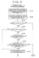
FIG. 2 is a flowchart showing steps of an opening degree maintenance control according to the first embodiment; -
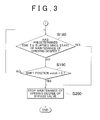
FIG. 3 is the flowchart showing steps of the opening degree maintenance control according to the first embodiment; -
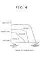
FIG. 4 is a conceptual diagram showing a relation between an engine rotational speed and an engine load, and a manner in which EGR gas is controlled according to the first embodiment; -
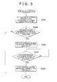
FIG. 5 is a flowchart showing steps of an EGR valve control according to the first embodiment; -
FIG. 6 is a timing chart showing changes in a situation when the opening degree maintenance control according to the first embodiment is executed; and -
FIG. 7 is a flowchart showing a portion of steps of an opening degree maintenance control according to a second embodiment of the invention. - Hereinafter, an exhaust gas recirculation apparatus according to a first embodiment of the invention, which is provided in a vehicle in which a manual transmission is provided, will be described in detail with reference to
FIG. 1 to FIG. 6 . -
FIG. 1 shows a configuration of a diesel engine to which the exhaust gas recirculation apparatus according to the first embodiment is applied. As shown inFIG. 1 , a diesel engine 10 (hereinafter, simply referred to as "engine") that includes a plurality of cylinders (four cylinders in the embodiment) is provided in avehicle 1. Anoutput shaft 31 of theengine 10 is connected to drivewheels 36 via aclutch mechanism 32, atransmission 33 that is a manual transmission, and anaxle 35. Theclutch mechanism 32 connects theoutput shaft 31 of theengine 10 to aninput shaft 34 of thetransmission 33, and disconnects theoutput shaft 31 of theengine 10 from theinput shaft 34 of thetransmission 33. The operating state of theclutch mechanism 32 will be described in detail. When aclutch pedal 43 is not operated, theclutch mechanism 32 is in a connection state in which theclutch mechanism 32 connects theoutput shaft 31 of theengine 10 to theinput shaft 34 of thetransmission 33. When theclutch pedal 43 is depressed, theclutch mechanism 32 is placed in a disconnection state in which theclutch mechanism 32 disconnects theoutput shaft 31 of theengine 10 from theinput shaft 34 of thetransmission 33. - In an
intake passage 11 of theengine 10, a compressor chamber of aturbocharger 12, anintercooler 13, and athrottle valve 14 are provided in the stated order in a direction from an upstream side to a downstream side. The compressor chamber of theturbocharger 12 compresses intake air using force of flowing exhaust gas. Theintercooler 13 cools the intake air whose temperature has been increased due to compression caused by theturbocharger 12. By adjusting the opening degree of thethrottle valve 14, the flow rate of the intake air is adjusted. - The
intake passage 11 is divided into intake sub-passages for the respective cylinders of theengine 10, at a position downstream of thethrottle valve 14. The intake sub-passages are connected tocombustion chambers 15 of the respective cylinders.Injectors 16 are disposed in thecombustion chambers 15 of the cylinders. Theinjectors 16 inject high-pressure fuel stored in acommon rail 17 into thecombustion chambers 15. - Exhaust sub-passages of an
exhaust passage 18 of theengine 10 are connected to the respective cylinders, and are combined into one exhaust passage. A portion of theexhaust passage 18, which is located downstream of a position at which the exhaust sub-passages are combined, is connected to an exhaust turbine of theturbocharger 12. In theexhaust passage 18, acatalytic converter 19 is provided downstream of the exhaust turbine of theturbocharger 12. A catalyst, which purifies exhaust gas, is carried by thecatalytic converter 19. - The
engine 10 is provided with an exhaust gas recirculation apparatus 20 (hereinafter, referred to as "EGR apparatus"). TheEGR apparatus 20 recirculates part of the exhaust gas (hereinafter, the part of the exhaust gas will be referred to as "EGR gas") from theexhaust passage 18, which is in an exhaust system, to theintake passage 11, which is in an intake system. TheEGR apparatus 20 includes an exhaust gas recirculation passage (hereinafter, referred to as "EGR passage") 23 through which the EGR gas is introduced from theexhaust passage 18 to theintake passage 11. In theEGR passage 23, anEGR cooler 24 is provided. TheEGR cooler 24 cools the EGR gas. TheEGR apparatus 20 also includes abypass passage 25 through which the EGR gas is introduced from theexhaust passage 18 to theintake passage 11 without passing through theEGR cooler 24. More specifically, thebypass passage 25 is provided so that the EGR gas flows from a portion of theEGR passage 23, which is located upstream of theEGR cooler 24 in a direction in which the EGR gas flows, to a portion of theEGR passage 23, which is located downstream of theEGR cooler 24 in the direction in which the EGR gas flows. Abypass valve 44, whose opening degree is adjustable, is provided in thebypass passage 25. AnEGR valve 27 is provided in theEGR passage 23 at a position downstream of a position at which theEGR passage 23 is connected to thebypass passage 25. TheEGR valve 27 adjusts the amount of the EGR gas introduced into theintake passage 11. A portion of theEGR passage 23, which is located downstream of theEGR valve 27, is connected to a portion of theintake passage 11, which is located downstream of thethrottle valve 14. - The
engine 10 is controlled by anelectronic control unit 28. Theelectronic control unit 28 includes a Center Processing Unit (CPU), a Read-Only Memory (ROM), a Random Access Memory (RAM), and input/output ports (I/O). The CPU performs computations relating to engine controls. In the ROM, programs and data used for the engine controls are stored. In the RAM, for example, results of the computations are temporarily stored. Signals from the outside are input to theelectronic control unit 28 and signals are output from theelectronic control unit 28 to the outside through the input/output ports. - The input ports of the
electronic control unit 28 are connected to a shift position sensor, anaccelerator sensor 45, and avehicle speed sensor 37. The shift position sensor detects a shift position "eshift" that is a position at which ashift lever 41 is located. Theaccelerator sensor 45 detects the depression amount of anaccelerator pedal 42 depressed by a driver of thevehicle 1. Thevehicle speed sensor 37 detects a vehicle speed SP of thevehicle 1 based on, for example, the rotation of the output shaft of thetransmission 33. Further, the input ports of theelectronic control unit 28 are connected to sensors that detect an engine operating state, such as aclutch switch 46, an airflow meter, and a crank angle sensor. Theclutch switch 46 detects the depression of theclutch pedal 43. The airflow meter detects the amount of intake air. The crank angle sensor detects the rotational angle (i.e., the crank angle) of theoutput shaft 31 of theengine 10. - Output ports of the
electronic control unit 28 are connected to drive circuits for, for example, thethrottle valve 14, theinjectors 16, thebypass valve 44, and theEGR valve 27. Theelectronic control unit 28 executes the engine controls such as an intake air reduction control and a fuel injection control, by outputting command signals to the drive circuits according to the engine operating state determined based on information from the sensors. - In the embodiment, the
electronic control unit 28 executes a bypass valve opening degree control and an EGR valve control included in the engine controls. Theelectronic control unit 28 executes the bypass valve opening degree control to control the opening degree of thebypass valve 44 based on an engine load. Theelectronic control unit 28 executes the EGR valve control to control the opening degree of theEGR valve 27. - By executing the bypass valve opening degree control, the
electronic control unit 28 controls the amount of the EGR gas passing through theEGR cooler 24, and the amount of the EGR gas passing through thebypass passage 25 in the total amount of the EGR gas, in theEGR apparatus 20. Thus, the temperature of thecatalytic converter 19 provided in theexhaust passage 18 is maintained at an appropriate high temperature. More specifically, when the engine load is low and an exhaust gas temperature is low, thebypass valve 44 is controlled to be fully opened to increase the amount of the EGR gas passing through thebypass passage 25, thereby suppressing a decrease in the exhaust gas temperature. When the engine load is high and the exhaust gas temperature is high, thebypass valve 44 is controlled to be fully closed to increase the amount of the EGR gas passing through theEGR cooler 24, thereby suppressing an excessive increase in the exhaust gas temperature. - By executing the EGR valve control, the
electronic control unit 28 adjusts the amount of the EGR gas flowing into theintake passage 11 through theEGR cooler 24 or thebypass passage 25. The EGR valve control and the bypass valve opening degree control will be described in detail later. - In the
vehicle 1 in which themanual transmission 33 is provided, when thetransmission 33 is performing a shift operation, the transmission is temporarily placed in a neutral state (i.e., a state in which transmission of drive power from theoutput shaft 31 of theengine 10 to theoutput shaft 35 of thetransmission 33 is interrupted). At this time, theaccelerator pedal 42 is released to suppress an increase in an engine rotational speed. That is, an engine output is temporarily decreased. In this case, because the engine load is decreased, the opening degree of thebypass valve 44 is changed according to the decrease in the engine load. - When the
transmission 33 is performing the shift operation, the engine load is temporarily decreased. After completion of the shift operation of thetransmission 33, the engine load is increased to a value corresponding to a speed ratio achieved after the gear shift. If the opening degree of thebypass valve 44 is changed each time thetransmission 33 performs the shift operation, the bypass valve may be unnecessarily operated. Therefore, for example, durability of thebypass valve 44 may be decreased. - Accordingly, in the embodiment, an opening degree maintenance control for the
EGR apparatus 20 is executed to reduce the possibility that thebypass valve 44 is unnecessarily operated when thetransmission 33 is performing the shift operation. The opening degree maintenance control maintains the opening degree of thebypass valve 44 when thetransmission 33 is performing the shift operation. Hereinafter, the opening degree maintenance control, the EGR valve control, and the bypass valve opening degree control will be described with reference toFIG. 2 to FIG. 6 . - First, a method of determining whether the
transmission 33 is performing the shift operation will be described. When thetransmission 33 is performing the shift operation, thetransmission 33 is placed in the neutral state. When thetransmission 33 is in the neutral state, the engine load is decreased to suppress an increase in the engine rotational speed. Accordingly, when a condition that thetransmission 33 is in the neutral state is satisfied, it may be determined that thetransmission 33 is performing the shift operation. However, when thetransmission 33 is the manual transmission, thetransmission 33 may be placed in the neutral state while the vehicle is in a stopped state. Therefore, it is not possible to determine whether thetransmission 33 is performing the shift operation using only the condition that "the transmission is in the neutral state". Thetransmission 33 performs the shift operation when the vehicle is traveling. Therefore, by adding a condition that a vehicle speed is equal to or higher than a predetermined speed, it is possible to avoid an erroneous determination that thetransmission 33 is performing the shift operation when thetransmission 33 is in the neutral state while the vehicle is in the stopped state. Thus, a first condition is used to determine that thetransmission 33 is performing the shift operation. The first condition is that thetransmission 33 is in the neutral condition, and the vehicle speed is equal to or higher than the predetermined speed, that is, the vehicle is traveling. That is, when the above-described first condition is satisfied, it is determined that thetransmission 33 is performing the shift operation. - When the
transmission 33 is to be placed in the neutral state during the gear shift, first, the driver releases theaccelerator pedal 42, and thus, the depression amount of theaccelerator pedal 42 is equal to or smaller than a predetermined amount. The depression amount of theaccelerator pedal 42 may be equal to or smaller than the predetermined amount, for example, when the vehicle is in the stopped state and theengine 10 is idling. In contrast, thetransmission 33 performs the shift operation when the vehicle is traveling, as described above. Therefore, by adding the condition that the vehicle speed is equal to or higher than the predetermined speed, it is possible to avoid an erroneous determination that thetransmission 33 is performing the shift operation when theengine 10 is idling. However, when deceleration fuel cutoff is being performed, the condition that the depression amount of theaccelerator pedal 42 is equal to or smaller than the predetermined amount and the vehicle speed is equal to or higher than the predetermined speed is satisfied. Therefore, it is necessary to determine whether the condition is satisfied due to the deceleration fuel cutoff. Thus, a second condition is also used to determine that thetransmission 33 is performing the shift operation. The second condition is a condition that the depression amount of theaccelerator pedal 42 is equal to or smaller than the predetermined amount, the vehicle speed is equal to or higher than the predetermined speed, and the deceleration fuel cutoff is not being performed. -
FIG. 2 shows steps of the opening degree maintenance control that may be regarded as the opening degree maintenance means employed in the embodiment. Processes in the control are repeatedly executed by theelectronic control unit 28 during the operation of theengine 10. - When the control is started, first, a bypass valve opening degree "ebypass" is read from a map based on the engine rotational speed and the engine load (step S110). A value detected by the crank angle sensor is used as the engine rotational speed. A fuel injection amount set based on the operation amount of the
accelerator pedal 42 is used as a parameter for the engine load. Based on the engine rotational speed and the engine load, the bypass valve opening degree "ebypass" is read from the map shown inFIG. 4 . More specifically, for example, when a value of the engine rotational speed and a value of the engine load are in a region A in the map shown inFIG. 4 , the bypass valve opening degree "ebypass" corresponding to the fully-opened state is read. When the value of the engine rotational speed and the value of the engine load are in a region B, the bypass valve opening degree "ebypass" corresponding to the fully-closed state is read. When the value of the engine rotational speed and the value of the engine load are in a region C, theEGR valve 27 is controlled to be fully closed. Thus, the bypass valve opening degree "ebypass" is maintained at, for example, a previous opening degree. - After the bypass valve opening degree "ebypass" is read from the map, the opening degree of the
bypass valve 44 is set to the bypass valve opening degree "ebypass" (step 120). The processes in step S110 and step S120 may be regarded as the bypass valve opening degree control. - Next, it is determined whether a vehicle speed SP is higher than "0" (step S 130). By determining whether this condition is satisfied, it is determined whether the
vehicle 1 is not in the stopped state. If it is determined that the vehicle speed SP is "0" (NO in step S130), it is determined that thevehicle 1 is in the stopped state, and the routine ends. - If it is determined that the vehicle speed SP is higher than "0" (YES in step S 130), it is determined that the
vehicle 1 is traveling, and a process in the next step S 140 is performed. In step S140, it is determined whether the shift position "eshift" is "1". The shift position "eshift" will be described. When theshift lever 41 is at a neutral position, the shift position "eshift" is "1". When theshift lever 41 is not at the neutral position, the shift position "eshift" is "0". The shift position "eshift" is detected by the shift position sensor. - If the shift position "eshift" is "1" (YES in step S140), the first condition is satisfied. Therefore, the opening degree of the
bypass valve 44 is maintained (step S 170). More specifically, the opening degree of thebypass valve 44 is maintained at the opening degree "ebypass" set in the processes in step S110 and step S120 that may be regarded as the bypass valve opening degree control. Thus, the opening degree of thebypass valve 44 is maintained at the opening degree set immediately before it is determined that thetransmission 33 is performing the shift operation. Then, the routine ends. - If the shift position "eshift" is "0" (NO in step S140), it is determined whether an accelerator depression amount ACCP is "0" (step S150). By determining whether this condition is satisfied, it is determined whether the driver of the
vehicle 1 has released theaccelerator pedal 42 to shift the gear. As the accelerator depression amount ACCP, a value detected by theaccelerator sensor 45 is used. If it is determined that the accelerator depression amount ACCP is not "0" (NO in step S 150), the routine ends. - If it is determined that the accelerator depression amount ACCP is "0" (YES in step S150), it is determined that the driver of the
vehicle 1 is shifting the gear, and then, it is determined whether the condition that the deceleration fuel cutoff is not being performed is satisfied (step S160). If it is determined that the deceleration fuel cutoff is being performed (NO in step S160), the routine ends. - If it is determined that the deceleration fuel cutoff is not being performed (YES in step S160), the second condition is satisfied, because an affirmative determination is made in step S130, an affirmative determination is made in step S150, and an affirmative determination is made in step S160. Accordingly, the opening degree of the
bypass valve 44 is maintained (step S170). - Thus, if one of the first condition and the second condition is satisfied, the opening degree of the
bypass valve 44 is maintained in step S 170. Further, in the opening degree maintenance control, it is determined that the maintenance of the opening degree of thebypass valve 44 should be stopped after a certain time elapses. Next, the control that stops the maintenance of the opening degree will be described in detail with reference toFIG. 3 . - After the opening degree of the
bypass valve 44 is maintained in step S 170 inFIG. 2 , it is determined whether a predetermined time Tα, has elapsed since start of maintenance of the opening degree of the bypass valve 44 (step S 180). - In the case of the manual transmission, it may take time to perform the shift operation, depending on driver's driving skill level. Thus, the depression amount of the
accelerator pedal 42 may remain equal to or smaller than the predetermined amount for a relatively long time, or thetransmission 33 may remain in the neutral state for a relatively long time. In this case, the opening degree of thebypass valve 44 is maintained for a relatively long time. The opening degree of thebypass valve 44 is maintained by the opening degree maintenance control to reduce the possibility that thebypass valve 44 is unnecessarily operated due to the temporal decrease in the engine load when thetransmission 33 is performing the shift operation. Therefore, it is not preferable that the opening degree of thebypass valve 44 be maintained for a relatively long time. That is, if the engine load remains decreased for a relatively long time, it is preferable to set the opening degree of thebypass valve 44 according to the decreased engine load. - Thus, in the embodiment, a process in step S 180 is performed to reduce the possibility that the opening degree of the
bypass valve 44 is maintained for a relatively long time. In step S 180, it is determined whether the predetermined time Tα has elapsed since the start of the maintenance of the opening degree of thebypass valve 44. For example, it is determined to be effective to stop the maintenance of the opening degree of thebypass valve 44, and to change the opening degree of thebypass valve 44 based on the engine load when the opening degree of thebypass valve 44 has been maintained for the predetermined time Tα by the opening degree maintenance control. The predetermined time Tα is empirically set in advance. - If it is determined that the predetermined time Tα has elapsed since the start of the maintenance of the opening degree of the bypass valve 44 (YES in step S 180), it is determined to be effective to change the opening degree of the
bypass valve 44 based on the engine load, and the maintenance of the opening degree of thebypass valve 44 is forcibly stopped (step S200). - If it is determined that the predetermined time Tα has not elapsed since the start of the maintenance of the opening degree of the bypass valve 44 (NO in step S 180), it is determined whether the shift position "eshift" is "0" (step S 190).
- If it is determined that the shift position "eshift" is "0" (YES in step S190), it is determined that the state of the
transmission 33 has been changed from the neutral state to the non-neutral state. Thus, the maintenance of the opening degree of thebypass valve 44 is stopped (step S200). - If it is determined that the shift position "eshift" is "1" (NO in step S190), it is determined that the
transmission 33 remains in the neutral state after the start of the maintenance of the opening degree of thebypass valve 44. Thus, the opening degree of thebypass valve 44 continues to be maintained. Thus, until an affirmative determination is made in step S 180 or step S 190, the opening degree of thebypass valve 44 continues to be maintained. - Thus, if the maintenance of the opening degree of the
bypass valve 44 is stopped when an affirmative determination is made in step S 180 or step S190. After the maintenance of the opening degree of thebypass valve 44 is stopped, the opening degree of thebypass valve 44 is adjusted based on the above-described map shown inFIG. 4 again. - In the diesel engine, if the opening degree of the
bypass valve 44 is adjusted to increase the amount of the EGR gas passing through thebypass passage 25 due to the temporal decrease in the engine load caused by the shift operation, after the opening degree of thebypass valve 44 has been adjusted so that a large amount of the EGR gas passes through theEGR cooler 24, a situation described below may occur. - A larger amount of exhaust gas at a relatively high temperature, which needs to be cooled by the
EGR cooler 24, is introduced into the cylinders through thebypass passage 25 and the like. Accordingly, a cylinder temperature is likely to increase. Although the exhaust gas temperature is temporarily decreased due to the temporal decrease in the engine load caused by the shift operation, there is a time lag between the decrease in the engine load and the decrease in the temperature of the exhaust gas in the exhaust system. Accordingly, when the engine load is temporarily decreased, the cylinder temperature is likely to increase for a certain time. When a combustion speed is low, a carbon component of fuel combusted in the cylinders is discharged as carbon dioxide. When the combustion speed is high, the carbon component is likely to be discharged as soot. Accordingly, if the engine load is increased again after the cylinder temperature has been likely to increase, the combustion speed, at which the fuel is combusted, is likely to increase, and the soot is likely to be generated. - However, in the embodiment, if it is determined that the
transmission 33 is performing the shift operation, the opening degree of thebypass valve 44 is maintained at an opening degree set immediately before it is determined that thetransmission 33 is performing the shift operation. Therefore, it is possible to reduce the possibility that the opening degree of thebypass valve 44 is adjusted to increase the amount of the EGR gas passing through thebypass passage 25 due to the temporal decrease in the engine load caused by the shift operation after the opening degree of thebypass valve 44 has been adjusted so that a large amount of the EGR gas passes through theEGR cooler 24. Also, it is possible to reduce the possibility that the exhaust gas at a relatively high temperature is introduced into the cylinders. Accordingly, it is possible to suppress the generation of the soot. - Even if the opening degree of the
bypass valve 44 is maintained so that the amount of the EGR gas passing through theEGR cooler 24 is maintained at a large amount, in other words, even if the amount of the EGR gas passing through thebypass passage 25 is maintained at a small amount, a certain amount of the exhaust gas at a high temperature is introduced into the cylinders through thebypass passage 25. Therefore, the soot may be generated. Also, even if thebypass valve 44 is controlled to be fully closed or fully opened as in the embodiment, the soot may be generated. That is, even if the opening degree of thebypass valve 44 is maintained at the opening degree corresponding to the fully-closed state to close thebypass passage 25, the residual EGR gas in a portion of thebypass passage 25, which is located downstream of thebypass valve 44, is introduced into the cylinders. Therefore, the soot may be generated also in this case. - Accordingly, in the embodiment, the EGR valve control, which may be regarded as the exhaust gas recirculation valve control means, is executed to suppress the generation of the soot. The EGR valve control will be described with reference to
FIG. 5 . The control is repeatedly executed by theelectronic control unit 28 during the operation of theengine 10, as well as the opening degree maintenance control. - As shown in
FIG. 5 , in the EGR valve control, first, an EGR valve opening degree "epegfin", which is the opening degree of theEGR valve 27, is set according to the engine operating state (step S210). When the engine operating state is in one of the region A and the region B in the map shown inFIG. 4 , the opening degree of theEGR valve 27 is set to an opening degree corresponding to the fully-opened state. When the engine operating state is in the region C, the opening degree of theEGR valve 27 is set to an opening degree corresponding to the fully-closed state. - Then, it is determined whether the opening degree of the
bypass valve 44 is being maintained (step S220). If it is determined that the opening degree of thebypass valve 44 is not being maintained (NO in step S220), the routine ends. - If it is determined that the opening degree of the
bypass valve 44 is being maintained (YES in step S220), a control that decreases the opening degree of the EGR valve 27 (hereinafter, the control will be referred to as "opening degree decrease control") is executed (step S230). More specifically, in the opening degree decrease control, the opening degree of theEGR valve 27 is controlled to an opening degree "epegfinα" so that the opening degree of theEGR valve 27 is smaller than the opening degree set according to the engine operating state in step S210. In the embodiment, the opening degree "epegfinα," is smaller than the opening degree corresponding to the fully-opened state of theEGR valve 27 by a decrease amount Δepegfin. Thus, the opening degree "epegfinα" is set to be slightly larger than the opening amount corresponding to the fully-closed state. The opening degree "epegfinα" is empirically set in advance so that the bed temperature of thecatalytic converter 19 is not decreased at the opening degree "epegfinα". If the engine operating state is in the region C in the map shown inFIG. 4 , and the opening degree of theEGR valve 27 is the opening degree corresponding to the fully-closed state, the opening degree of theEGR valve 27 is maintained at the opening degree corresponding to the fully-closed state. The decrease amount Δepegfin may be variably set based on the exhaust gas temperature. In the case where the opening degree of theEGR valve 27 is variably set to an opening degree in a range from the opening degree corresponding to the fully-closed state to the opening degree corresponding to the fully-opened state, according to the engine operating state, the opening degree of theEGR valve 27 may be controlled to a value smaller than the opening degree set based on the engine operating state. - Then, in the next step S240, the opening degree decrease control that decreases the opening degree of the
EGR valve 27, that is, the control that decreases the opening degree of theEGR valve 27 to the opening degree "epegfinα" continues to be executed as long as it is determined that the maintenance of the opening degree of thebypass valve 44 has not been stopped (NO in step S240). That is, the opening degree decrease control is repeatedly executed until it is determined that the maintenance of the opening degree of thebypass valve 44 has been stopped. If it is determined that the maintenance of the opening degree of thebypass valve 44 has been stopped (YES in step S240), the opening degree decrease control that decreases the opening degree of theEGR valve 24 ends (step S250). Thus, the opening degree of theEGR valve 27 is adjusted based on the map shown inFIG. 4 , again. - Changes in the situation when the opening degree maintenance control and the EGR valve control are executed according to the embodiment will be described with reference to
FIG. 6. FIG. 6 shows the case in which when the engine operating state is in the region B inFIG. 4 , that is, when the opening degree of thebypass valve 44 is controlled to the opening degree corresponding to the fully-closed state, and the opening degree of theEGR valve 27 is controlled to the opening degree corresponding to the fully-opened state, the opening degree maintenance control and the EGR valve control are executed. - As shown in
FIG. 6 , when thetransmission 33 performs the shift operation, first, the driver of thevehicle 1 releases theaccelerator pedal 42, and thus, the accelerator depression amount ACCP is decreased to "0" (at a timing t1). At this time, if the opening degree maintenance control is not executed, thebypass valve 44 is fully opened due to the decrease in the engine load as shown by a chain line inFIG. 6 . In contrast, in the embodiment, at the timing t1, it is determined that the vehicle speed SP is higher than "0", and the deceleration fuel cutoff is not being performed, and therefore, the opening degree of thebypass valve 44 is maintained, and thus, the opening degree of thebypass valve 44 is maintained at the opening degree corresponding to the fully-closed state. Then, the driver of thevehicle 1 operates theshift lever 41, and thus, the shift position "eshift" is changed from "0" indicating that thetransmission 33 is in a given gear, to "1" indicating that thetransmission 33 is in the neutral state (at a timing t2). Thus, as shown inFIG. 6 , when the condition that the accelerator depression amount ACCP is "0", the vehicle speed SP is higher than "0", and the deceleration fuel cutoff is not being performed is satisfied, the opening degree of thebypass valve 44 starts to be maintained before the shift position "eshift" is changed to "1" indicating that thetransmission 33 is in the neutral state. - When the opening degree of the
bypass valve 44 is being maintained, the opening degree decrease control that decreases the opening degree of theEGR valve 27 is executed. Thus, the opening degree of theEGR valve 27 is set to the opening degree "epegfinα" that is smaller than the opening degree corresponding to the fully-opened state by the decrease amount Δepegfin. - When the driver of the
vehicle 1 finishes the operation of theshift lever 41, and thus, the shift position "eshift" is changed from "1" to "0" (at a timing t3) while the opening degree of thebypass valve 44 is being maintained, the maintenance of the opening degree of thebypass valve 44 is stopped. In addition, when the maintenance of the opening degree of thebypass valve 44 is stopped, the opening degree decrease control that decreases the opening degree of theEGR valve 27 ends. - Although not shown in
FIG. 6 , the opening degree of thebypass valve 44 may be maintained upon the satisfaction of the condition that the vehicle speed SP is higher than "0" and the shift position "eshift" is changed from "0" to "1", instead of the condition that the accelerator depression amount ACCP is "0", the vehicle speed SP is higher than "0", and the deceleration fuel cutoff is not being performed. In this case, the opening degree of thebypass valve 44 starts to be maintained at the timing t2 inFIG. 6 , at which the shift position "eshift" is changed from "0" to "1". - The maintenance of the opening degree of the
bypass valve 44 may be stopped due to the satisfaction of the condition that the predetermined time Tα has elapsed since the start of the maintenance of the opening degree of thebypass valve 44, instead of the condition that the shift position "eshift" is changed from "1" to "0". In this case, if the predetermined time Tα elapses at a timing in a period from the timing t1 at which the opening degree of thebypass valve 44 starts to be maintained, to the timing t3 at which the change of the shift position "eshift" from "1" to "0" is completed inFIG. 6 , the maintenance of the opening degree of thebypass valve 44 is stopped at the timing at which the predetermined time Tα elapses. - According to the embodiment that has been described, it is possible to obtain the following advantageous effects. (1) When the engine load is temporarily decreased due to the shift operation of the
transmission 33, the opening degree of thebypass valve 44 is maintained at an opening degree set immediately before thetransmission 33 performs the shift operation. Accordingly, it is possible to reduce the possibility that the opening degree of thebypass valve 44 is changed each time thetransmission 33 performs the shift operation. Thus, it is possible to reduce the possibility that thebypass valve 44 is unnecessarily operated due to the shift operation. - (2) When the first condition is satisfied, it is determined that the
transmission 33 is performing the shift operation. The first condition is the condition that thetransmission 33 is in the neutral state, and the vehicle speed SP is higher than "0", that is, thevehicle 1 is traveling. Thus, the opening degree maintenance control maintains the opening degree of thebypass valve 44, in accordance with the temporal decrease in the engine load. - (3) The second condition is used to determine that the
manual transmission 33 is performing the shift operation. The second condition is the condition that the accelerator depression amount ACCP is "0", the vehicle speed SP is higher than "0", and the deceleration fuel cutoff is not being performed. That is, when the second condition is satisfied, it is determined that thetransmission 33 is performing the shift operation. Thus, the opening degree maintenance control maintains the opening degree of the bypass valve in accordance with the temporal decrease in the engine load. - (4) When the manual transmission performs the shift operation, the transmission is placed in the neutral state after the depression amount of the
accelerator pedal 42 depressed by the driver is decreased to an amount equal to or smaller than the predetermined amount. Therefore, if the opening degree maintenance control starts to maintain the opening degree of thebypass valve 44 after it is detected that thetransmission 33 is in the neutral state, the timing, at which the opening degree of thebypass valve 44 starts to be maintained, may lag behind the decrease in the engine load. - However, in the embodiment, the opening degree of the
bypass valve 44 starts to be maintained at the timing at which the decrease in the depression amount of theaccelerator pedal 42 is detected. The depression amount of theaccelerator pedal 42 is always decreased before thetransmission 33 is placed in the neutral state. Thus, it is possible to appropriately reduce the time lag between the timing at which the engine load is decreased and the timing at which the opening degree of thebypass valve 44 starts to be maintained. - (5) There is a limit on the time during which the opening degree of the
bypass valve 44 is maintained. Therefore, the opening degree of thebypass valve 44 is appropriately maintained, regardless of the driver's driving skill level, for example, regardless of the variation in the time required for the driver to perform a shift operation. - (6) The maintenance of the opening degree of the
bypass valve 44 is stopped when thetransmission 33, which has been temporarily in the neutral state, is brought to the non-neutral state while thetransmission 33 is performing the shift operation, that is, when the state of thetransmission 33 starts to change so that thetransmission 33 starts to shift toward a target gear, and the engine load, which has been temporarily decreased, starts to increase. Thus, in the embodiment, it is possible to appropriately set the timing at which the maintenance of the opening degree of thebypass valve 44 is stopped. - (7) In the diesel engine, if the opening degree of the
bypass valve 44 is adjusted to increase the amount of the EGR gas passing through thebypass passage 25 due to the temporal decrease in the engine load caused by the shift operation, after the opening degree of thebypass valve 44 has been adjusted so that a large amount of the EGR gas passes through theEGR cooler 24, the soot may be particularly likely to be generated. However, in the embodiment, if it is determined that thetransmission 33 is performing the shift operation, the opening degree of thebypass valve 44 is maintained at an opening degree set immediately before it is determined that thetransmission 33 is performing the shift operation. Therefore, it is possible to reduce the possibility that the opening degree of thebypass valve 44 is adjusted to increase the amount of the EGR gas passing through thebypass passage 25 due to the temporal decrease in the engine load caused by the shift operation after the opening degree of thebypass valve 44 has been adjusted so that a large amount of the EGR gas passes through theEGR cooler 24. Also, it is possible to reduce the possibility that the exhaust gas at a relatively high temperature is introduced into the cylinders. Accordingly, it is possible to suppress the generation of the soot. - (8) The opening degree decrease control, which decreases the opening degree of the
EGR valve 27, is executed in accordance with the maintenance of the opening degree of thebypass valve 44. Therefore, it is possible to reduce the amount of the EGR gas introduced into the cylinders. Accordingly, it is possible to reliably suppress the generation of the soot. - Hereinafter, an exhaust gas recirculation apparatus according to a second embodiment of the invention will be described in detail with reference to
FIG. 7 . The configuration of the diesel engine (hereinafter, simply referred to as "engine") 10 in the second embodiment is different from the configuration of theengine 10 shown inFIG. 1 in the first embodiment. A portion of the opening degree maintenance control that maintains the opening degree of the bypass valve in the second embodiment is different from a portion of the opening degree maintenance control shown inFIG. 2 in the first embodiment. Hereinafter, the exhaust gas recirculation apparatus in the second embodiment will be described with focus on the differences between the first and second embodiments. In the second embodiment, the EGR valve control shown inFIG. 5 is executed as in the first embodiment. - In the embodiment, the
transmission 33 provided in theengine 10 is an automatic transmission. Thetransmission 33 automatically shifts according to the traveling state of thevehicle 1. As is known, when the automatic transmission is performing the shift operation, the automatic transmission is temporarily placed in the neutral state. When the automatic transmission is temporarily placed in the neutral state, the engine load is temporarily decreased due to the decrease in the engine load. -
FIG. 7 shows steps of the opening degree maintenance control that may be regarded as the opening degree maintenance means in the embodiment. The control is repeatedly executed by theelectronic control unit 28 during the operation of theengine 10. In the opening degree maintenance control, first, the bypass valve opening degree "ebypass" is read from the map based on the engine rotational speed and the engine load (step S110), and the opening degree of thebypass valve 44 is set to the bypass valve opening degree "ebypass" that is read (step S120), as in the steps of the control shown inFIG. 2 . The manner in which the opening degree of thebypass valve 44 is set is the same as that in the first embodiment. - After the opening degree of the
bypass valve 44 is set to the opening degree "ebypass" in step S120, it is determined whether a neutral signal is "1" (step S330) in the opening degree maintenance control in the second embodiment. The neutral signal is "1" when a neutral request is output from a control device that executes a shift control for the automatic transmission. The neutral signal is "0" when the neutral request is not output from the control device. By determining whether the neutral signal is "1", it is determined whether thetransmission 33 is in the neutral state. If it is determined that the neutral signal is "0" (NO in step S330), it is determined that thetransmission 33 is not in the neutral state. Then, the routine ends. - If it is determined that the neutral signal is "1" (YES in step S330), it is determined that the
transmission 33 is in the neutral state. Then, the next process is performed. In the second embodiment, thetransmission 33 is placed in the neutral state to reduce fuel consumption even when the vehicle is in the stopped state. Therefore, it is not possible to determine whether thetransmission 33 is performing the shift operation using only the condition that "the transmission is in the neutral state". Thetransmission 33 performs the shift operation when the vehicle is traveling. Therefore, by adding the condition that the vehicle speed is equal to or higher than the predetermined speed, it is possible to avoid an erroneous determination that thetransmission 33 is performing the shift operation when thetransmission 33 is in the neutral state while the vehicle is in the stopped state. - In the next step S340, it is determined whether the vehicle speed SP is higher than "0". By determining whether this condition is satisfied, it is determined whether the
vehicle 1 is not in the stopped state. If it is determined that the vehicle speed SP is "0" (NO in step S340), it is determined that thevehicle 1 is in the stopped state, and the routine ends. If it is determined that the vehicle speed SP is higher than "0" (YES in step S340), it is determined that thevehicle 1 is traveling, and the opening degree of thebypass valve 44 is maintained (step S350). - The conditions used in the determination processes in step S330 and step S340 are the conditions for determining whether the
transmission 33 is performing the shift operation. If the conditions are satisfied, the opening degree of thebypass valve 44 is maintained in step S350. - Next, after the opening degree of the
bypass valve 44 is maintained in step S350, it is determined whether the neutral signal is "0" (step S360). If it is determined that the neutral signal is "1" (NO in step S360), it is determined that thetransmission 33 remains in the neutral state, and the opening degree of thebypass valve 44 continues to be maintained. Thus, the opening degree of thebypass valve 44 continues to be maintained until an affirmative determination is made in step S360. - If it is determined that the neutral signal is "0" (YES in step S360), it is determined that the state of the
transmission 33 has been changed from the neutral state to the non-neutral state, and the maintenance of the opening degree of thebypass valve 44 is stopped (step S370). Thus, after the maintenance of the opening degree of thebypass valve 44 is stopped, the opening degree of thebypass valve 44 is adjusted based on the map shown inFIG. 4 again. - According to the second embodiment that has been described, when the
transmission 33 is the automatic transmission, it is possible to obtain the advantageous effects (1), (2), and (6) to (8) that are obtained in the first embodiment. - The invention may be realized in the following embodiments made by appropriately modifying the above-described embodiments. In the first embodiment, the condition that the
shift lever 41 is at the neutral position is employed as the condition for determining that thetransmission 33 is in the neutral state. In a modified embodiment, it may be determined that thetransmission 33 is in the neutral state when it is detected that the clutch pedal is depressed. - In the first and second embodiments, the opening degree of the
bypass valve 44 is adjusted to be fully opened or fully closed according to the engine operating state. However, the manner, in which thebypass valve 44 is adjusted, is not limited to this manner. The opening degree of thebypass valve 44 may be appropriately changed in a range from the opening degree corresponding to the fully-opened state to the opening degree corresponding to the fully-closed state, according to the engine operating state. - In the first and second embodiments, the opening degree of the
EGR valve 27 is adjusted to be fully opened or fully closed according to the engine operating state. However, the manner, in which theEGR valve 27 is adjusted, is not limited to this manner. The opening degree of the EGR valve may be appropriately changed in a range from the opening degree corresponding to the fully-opened state to the opening degree corresponding to the fully-closed state, according to the engine operating state. - In the first and second embodiments, the opening degree of the
EGR valve 27 is controlled to the opening degree "epegfinα" regardless of the opening degree of thebypass valve 44. In a modified embodiment, the opening degree "epegfinα" may be set according to the opening degree of thebypass valve 44 each time the opening degree decrease control, which decreases the opening degree of theEGR valve 27, is executed. However, the opening degree "epegfinα" needs to be set to be smaller than the opening degree set according to the engine operating state. Also, it is preferable that the opening degree "epegfinα" should be set so that the bed temperature of the catalytic converter is not decreased at the opening degree "epegfinα". In the modified embodiment as well, it is possible to obtain the advantageous effect (8) obtained in the first and second embodiments. - The EGR valve control shown in
FIG. 5 may be omitted. In the second embodiment, when the neutral signal is "1", it is determined that thetransmission 33 is in the neutral state. In a modified embodiment, it may be determined whether the automatic transmission is in the neutral state by detecting operating states of valves that are operated to bring the automatic transmission to the neutral state, for example, hydraulic valves. - In the first embodiment, the first condition and the second condition are set as the conditions for determining whether the transmission is performing the shift operation. However, one of the first and second conditions may be set.
- In the first embodiment, the process in step S 180 may be omitted. In the first embodiment, the condition that the accelerator depression amount ACCP is "0" is employed as the condition for determining that the
accelerator pedal 42 has been released by the driver of thevehicle 1. In a modified embodiment, a predetermined depression amount other than "0" may be set, and a condition that the accelerator depression amount ACCP is equal to or smaller than the predetermined depression amount may be employed as the condition for determining that the accelerator pedal has been released. The predetermined depression amount employed in the condition is a value at which it is determined that the accelerator pedal has been released, and which is set in advance, for example, empirically. - In the first and second embodiments, the condition that the vehicle speed SP is higher than "0" is employed as the condition for determining that the
vehicle 1 is traveling. In a modified embodiment, a predetermined speed other than "0" may be set, and a condition that the vehicle speed SP is equal to or higher than the predetermined speed may be employed as the condition for determining that the vehicle is traveling. The predetermined speed of the vehicle speed SP employed in the condition is a value at which it is determined that the vehicle is traveling, and which is set in advance, for example, empirically. - In the first and second embodiments, the invention is applied to the vehicle that includes the diesel engine. However, the invention is not limited to the diesel engine. The invention may be applied to, for example, a gasoline engine, as long as the gasoline engine is an internal combustion engine provided with an exhaust gas recirculation apparatus that includes an EGR cooler and a bypass passage. In the modified embodiments as well, it is possible to obtain at least advantageous effects similar to the advantageous effects (1) to (6) obtained in the first and second embodiments.
Claims (14)
- An exhaust gas recirculation apparatus (20) applied to an internal combustion engine (10) connected to a transmission (33), wherein when the transmission is placed in a neutral state while the transmission is performing a shift operation, an engine load is temporarily decreased; the exhaust gas recirculation apparatus includes an exhaust gas recirculation passage (23) through which part of exhaust gas is introduced from an exhaust system (18) to an intake system (11), a cooler (24) which is provided in the exhaust gas recirculation passage, and which cools the exhaust gas, a bypass passage (25) through which the exhaust gas is introduced from the exhaust system to the intake system without passing through the cooler, and a bypass valve (44) provided in the bypass passage; and an amount of the exhaust gas flowing through the cooler and an amount of the exhaust gas flowing through the bypass passage are adjusted by changing an opening degree of the bypass valve based on the engine load, the exhaust gas recirculation apparatus being characterized by comprising:opening degree maintenance means for, if it is determined that the transmission (33) is performing the shift operation, maintaining the opening degree of the bypass valve (44) at an opening degree set immediately before it is determined that the transmission (33) is performing the shift operation.
- The exhaust gas recirculation apparatus according to claim 1, wherein
when a first condition is satisfied, it is determined that the transmission (33) is performing the shift operation; and
the first condition is a condition that the transmission (33) is in the neutral state and a vehicle speed is equal to or higher than a predetermined speed. - The exhaust gas recirculation apparatus according to claim 1, wherein
the transmission (33) is a manual transmission (33);
when a second condition is satisfied, it is determined that the transmission (33) is performing the shift operation; and
the second condition is a condition that a depression amount of an accelerator pedal (42) is equal to or smaller than a predetermined amount, a vehicle speed is equal to or higher than a predetermined speed, and deceleration fuel cutoff is not being performed. - The exhaust gas recirculation apparatus according to claim 1, wherein
the transmission (33) is a manual transmission (33); and
when a first condition or a second condition is satisfied, it is determined that the transmission (33) is performing the shift operation; and
the first condition is a condition that the transmission (33) is in the neutral state and a vehicle speed is equal to or higher than a predetermined speed, and the second condition is a condition that a depression amount of an accelerator pedal (42) is equal to or smaller than a predetermined amount, a vehicle speed is equal to or higher than a predetermined speed, and deceleration fuel cutoff is not being performed. - The exhaust gas recirculation apparatus according to claim 3 or 4, wherein
when a predetermined time (Tα) has elapsed since start of maintenance of the opening degree of the bypass valve (44), the opening degree maintenance means stops the maintenance of the opening degree of the bypass valve (44). - The exhaust gas recirculation apparatus according to any one of claims 1 to 5,
when a state of the transmission (33) is changed from the neutral state to a non-neutral state, the opening degree maintenance means stops maintenance of the opening degree of the bypass valve (44). - The exhaust gas recirculation apparatus according to any one of claims 1 to 6, wherein
the internal combustion engine (10) is a diesel engine. - The exhaust gas recirculation apparatus according to claim 7, wherein
the exhaust gas recirculation passage (23) further includes an exhaust gas recirculation valve (27) that adjusts an amount of the exhaust gas introduced from the exhaust system to the intake system, and exhaust gas recirculation valve control means for setting an opening degree of the exhaust gas recirculation valve (27) according to an engine operating state; and
while the opening degree maintenance means is maintaining the opening degree of the bypass valve (44), the exhaust gas recirculation valve control means controls the opening degree of the exhaust gas recirculation valve (27) to a value smaller than the opening degree set according to the engine operating state. - The exhaust gas recirculation apparatus according to claim 8, wherein
while the opening degree maintenance means is maintaining the opening degree of the bypass valve (44), the exhaust gas recirculation valve control means controls the opening degree of the exhaust gas recirculation valve (27) to a predetermined value (epegfinα) that is smaller than an opening degree corresponding to a fully-opened state by a predetermined decrease amount (Δepegfin), and that is larger than an opening degree corresponding to a fully-closed state. - The exhaust gas recirculation apparatus according to claim 9, wherein
the predetermined decrease amount (Δepegfin) is variably set based on a temperature of the exhaust gas. - A method of controlling an exhaust gas recirculation apparatus (20) applied to an internal combustion engine (10) connected to a transmission (33), wherein when the transmission is placed in a neutral state while the transmission is performing a shift operation, an engine load is temporarily decreased; the exhaust gas recirculation apparatus includes an exhaust gas recirculation passage (23) through which part of exhaust gas is introduced from an exhaust system (18) to an intake system (11), a cooler (24) which is provided in the exhaust gas recirculation passage, and which cools the exhaust gas, a bypass passage (25) through which the exhaust gas is introduced from the exhaust system to the intake system without passing through the cooler, and a bypass valve (44) provided in the bypass passage; and an amount of the exhaust gas flowing through the cooler and an amount of the exhaust gas flowing through the bypass passage are adjusted by changing an opening degree of the bypass valve, the method being characterized by comprising:setting the opening degree of the bypass valve (44) based on the engine load;determining whether the transmission (33) is performing the shift operation; andif it is determined that the transmission (33) is performing the shift operation, maintaining the opening degree of the bypass valve (44) at an opening degree set immediately before it is determined that the transmission (33) is performing the shift operation.
- The method according to claim 11, characterized by further comprising:determining whether a predetermined time (Tα) has elapsed since start of maintenance of the opening degree of the bypass valve (44); andstopping the maintenance of the opening degree of the bypass valve (44), if it is determined that the predetermined time (Tα) has elapsed since start of the maintenance of the opening degree of the bypass valve (44).
- The method according to claim 11, characterized by further comprising:determining whether a state of the transmission (33) has been changed from the neutral state to a non-neutral state; andstopping maintenance of the opening degree of the bypass valve (44), if it is determined that the state of the transmission (33) has been changed from the neutral state to the non-neutral state.
- The method according to any one of claims 11 to 13, wherein
the exhaust gas recirculation passage (23) further includes an exhaust gas recirculation valve (27) that adjusts an amount of the exhaust gas introduced from the exhaust system to the intake system; and
the method further comprises:setting an opening degree of the exhaust gas recirculation valve (27) according to an engine operating state;determining whether the opening degree of the bypass valve (44) is being maintained;executing a control that decreases the opening degree of the exhaust gas recirculation valve (27) to a value smaller than the opening degree set according to the engine operating state, if it is determined that the opening degree of the bypass valve (44) is being maintained;determining whether maintenance of the opening degree of the bypass valve (44) has been stopped; andending the control, if it is determined that the maintenance of the opening degree of the bypass valve (44) has been stopped.
Applications Claiming Priority (1)
| Application Number | Priority Date | Filing Date | Title |
|---|---|---|---|
| JP2009006020A JP4687793B2 (en) | 2009-01-14 | 2009-01-14 | Exhaust gas recirculation device |
Publications (2)
| Publication Number | Publication Date |
|---|---|
| EP2208878A1 true EP2208878A1 (en) | 2010-07-21 |
| EP2208878B1 EP2208878B1 (en) | 2013-11-06 |
Family
ID=42079116
Family Applications (1)
| Application Number | Title | Priority Date | Filing Date |
|---|---|---|---|
| EP10150638.4A Not-in-force EP2208878B1 (en) | 2009-01-14 | 2010-01-13 | Exhaust gas recirculation apparatus and method of controlling exhaust gas recirculation apparatus |
Country Status (2)
| Country | Link |
|---|---|
| EP (1) | EP2208878B1 (en) |
| JP (1) | JP4687793B2 (en) |
Cited By (4)
| Publication number | Priority date | Publication date | Assignee | Title |
|---|---|---|---|---|
| GB2503726A (en) * | 2012-07-05 | 2014-01-08 | Gm Global Tech Operations Inc | Internal combustion engine having EGR cooler bypass circuit and bypass control valve |
| CN109690056A (en) * | 2016-09-02 | 2019-04-26 | 日产自动车株式会社 | Control method for internal combustion engine and control device for internal combustion engine |
| CN112523877A (en) * | 2020-10-21 | 2021-03-19 | 广西玉柴机器股份有限公司 | Control method for high-pressure exhaust gas recirculation cooling bypass valve |
| CN116136200A (en) * | 2021-11-17 | 2023-05-19 | 潍柴动力股份有限公司 | A kind of control method of engine system and EGR cooler bypass valve |
Families Citing this family (3)
| Publication number | Priority date | Publication date | Assignee | Title |
|---|---|---|---|---|
| KR101360445B1 (en) | 2012-12-17 | 2014-02-12 | 현대자동차주식회사 | Egr system control method for engine |
| JP6252067B2 (en) * | 2013-09-20 | 2017-12-27 | いすゞ自動車株式会社 | EGR device and exhaust gas recirculation method |
| JP2022025995A (en) | 2020-07-30 | 2022-02-10 | 株式会社東芝 | Semiconductor device |
Citations (6)
| Publication number | Priority date | Publication date | Assignee | Title |
|---|---|---|---|---|
| JPS6093166A (en) * | 1983-10-28 | 1985-05-24 | Isuzu Motors Ltd | Exhaust gas circulation device |
| JPS6185563A (en) * | 1984-10-01 | 1986-05-01 | Mazda Motor Corp | Exhaust gas recycling device for engine |
| US4757683A (en) * | 1985-09-25 | 1988-07-19 | Honda Giken Kogyo Kabushiki Kaisha | Exhaust gas recirculation method for internal combustion engines |
| WO2004058534A1 (en) * | 2002-12-30 | 2004-07-15 | Volvo Lastvagnar Ab | Method of regulating egr in an internal combustion engine and vehicle with an engine with electronic means for applying the method |
| US20080040085A1 (en) * | 2006-08-10 | 2008-02-14 | Southwest Research Institute | Dynamic modeling of an internal combustion engine operating with multiple combustion modes |
| JP2008138638A (en) | 2006-12-05 | 2008-06-19 | Toyota Motor Corp | Exhaust gas recirculation device for internal combustion engine |
Family Cites Families (3)
| Publication number | Priority date | Publication date | Assignee | Title |
|---|---|---|---|---|
| JPH0968063A (en) * | 1995-08-30 | 1997-03-11 | Mazda Motor Corp | Engine controller |
| JP3717311B2 (en) * | 1998-09-04 | 2005-11-16 | 日野自動車株式会社 | Engine exhaust gas recirculation system |
| JP4209350B2 (en) * | 2004-03-11 | 2009-01-14 | トヨタ自動車株式会社 | Supercharger control device |
-
2009
- 2009-01-14 JP JP2009006020A patent/JP4687793B2/en not_active Expired - Fee Related
-
2010
- 2010-01-13 EP EP10150638.4A patent/EP2208878B1/en not_active Not-in-force
Patent Citations (6)
| Publication number | Priority date | Publication date | Assignee | Title |
|---|---|---|---|---|
| JPS6093166A (en) * | 1983-10-28 | 1985-05-24 | Isuzu Motors Ltd | Exhaust gas circulation device |
| JPS6185563A (en) * | 1984-10-01 | 1986-05-01 | Mazda Motor Corp | Exhaust gas recycling device for engine |
| US4757683A (en) * | 1985-09-25 | 1988-07-19 | Honda Giken Kogyo Kabushiki Kaisha | Exhaust gas recirculation method for internal combustion engines |
| WO2004058534A1 (en) * | 2002-12-30 | 2004-07-15 | Volvo Lastvagnar Ab | Method of regulating egr in an internal combustion engine and vehicle with an engine with electronic means for applying the method |
| US20080040085A1 (en) * | 2006-08-10 | 2008-02-14 | Southwest Research Institute | Dynamic modeling of an internal combustion engine operating with multiple combustion modes |
| JP2008138638A (en) | 2006-12-05 | 2008-06-19 | Toyota Motor Corp | Exhaust gas recirculation device for internal combustion engine |
Cited By (5)
| Publication number | Priority date | Publication date | Assignee | Title |
|---|---|---|---|---|
| GB2503726A (en) * | 2012-07-05 | 2014-01-08 | Gm Global Tech Operations Inc | Internal combustion engine having EGR cooler bypass circuit and bypass control valve |
| CN109690056A (en) * | 2016-09-02 | 2019-04-26 | 日产自动车株式会社 | Control method for internal combustion engine and control device for internal combustion engine |
| CN112523877A (en) * | 2020-10-21 | 2021-03-19 | 广西玉柴机器股份有限公司 | Control method for high-pressure exhaust gas recirculation cooling bypass valve |
| CN112523877B (en) * | 2020-10-21 | 2022-08-30 | 广西玉柴机器股份有限公司 | Control method for high-pressure exhaust gas recirculation cooling bypass valve |
| CN116136200A (en) * | 2021-11-17 | 2023-05-19 | 潍柴动力股份有限公司 | A kind of control method of engine system and EGR cooler bypass valve |
Also Published As
| Publication number | Publication date |
|---|---|
| JP4687793B2 (en) | 2011-05-25 |
| EP2208878B1 (en) | 2013-11-06 |
| JP2010163938A (en) | 2010-07-29 |
Similar Documents
| Publication | Publication Date | Title |
|---|---|---|
| US7036305B2 (en) | Exhaust gas purification device of engine for vehicle | |
| US20180128145A1 (en) | Method and system for an exhaust diverter valve | |
| EP2208878B1 (en) | Exhaust gas recirculation apparatus and method of controlling exhaust gas recirculation apparatus | |
| KR101601157B1 (en) | Engine system having turbo charger and super charger | |
| US20100000500A1 (en) | Egr system for internal combustion engine and method for controlling the same | |
| JP5187123B2 (en) | Control device for internal combustion engine | |
| US9464586B2 (en) | Exhaust gas recirculation system of engine | |
| WO2014020982A1 (en) | Control device for internal combustion engine | |
| EP2211044B1 (en) | EGR controller and EGR control method for internal combustion engine | |
| US7913549B2 (en) | Transition from exhaust braking to exhaust particulate filter regeneration in a diesel engine | |
| JP2014227844A (en) | Controller of internal combustion engine | |
| JP2006194143A (en) | Engine control device | |
| JP6458480B2 (en) | Exhaust gas recirculation control device | |
| JP2007303437A (en) | Control device for internal combustion engine | |
| US8229654B2 (en) | Device for limiting output of internal combustion engine when the engine has abnormality | |
| JP6107678B2 (en) | Abnormality diagnosis device for variable valve mechanism | |
| JP5394775B2 (en) | Control device for internal combustion engine | |
| JP4736978B2 (en) | Exhaust gas recirculation device for internal combustion engine | |
| JP4479524B2 (en) | Start control device for compression ignition internal combustion engine | |
| JP5771911B2 (en) | Automatic stop / restart system for compression ignition internal combustion engine | |
| JP7512905B2 (en) | Engine equipment | |
| JP6236893B2 (en) | Exhaust gas recirculation device and exhaust gas recirculation method for an internal combustion engine with a turbocharger | |
| JP2007332912A (en) | Control device for internal combustion engine | |
| EP1479898B1 (en) | Combustion control apparatus for internal combustion engine | |
| CN111433445B (en) | Method and device for controlling internal combustion engine for vehicle |
Legal Events
| Date | Code | Title | Description |
|---|---|---|---|
| PUAI | Public reference made under article 153(3) epc to a published international application that has entered the european phase |
Free format text: ORIGINAL CODE: 0009012 |
|
| 17P | Request for examination filed |
Effective date: 20100113 |
|
| AK | Designated contracting states |
Kind code of ref document: A1 Designated state(s): AT BE BG CH CY CZ DE DK EE ES FI FR GB GR HR HU IE IS IT LI LT LU LV MC MK MT NL NO PL PT RO SE SI SK SM TR |
|
| AX | Request for extension of the european patent |
Extension state: AL BA RS |
|
| RIC1 | Information provided on ipc code assigned before grant |
Ipc: F02M 25/07 20060101ALI20110520BHEP Ipc: F02D 41/00 20060101ALI20110520BHEP Ipc: F02D 19/00 20060101AFI20110520BHEP |
|
| RAP1 | Party data changed (applicant data changed or rights of an application transferred) |
Owner name: TOYOTA JIDOSHA KABUSHIKI KAISHA |
|
| GRAP | Despatch of communication of intention to grant a patent |
Free format text: ORIGINAL CODE: EPIDOSNIGR1 |
|
| INTG | Intention to grant announced |
Effective date: 20130527 |
|
| GRAS | Grant fee paid |
Free format text: ORIGINAL CODE: EPIDOSNIGR3 |
|
| GRAA | (expected) grant |
Free format text: ORIGINAL CODE: 0009210 |
|
| AK | Designated contracting states |
Kind code of ref document: B1 Designated state(s): AT BE BG CH CY CZ DE DK EE ES FI FR GB GR HR HU IE IS IT LI LT LU LV MC MK MT NL NO PL PT RO SE SI SK SM TR |
|
| REG | Reference to a national code |
Ref country code: GB Ref legal event code: FG4D |
|
| REG | Reference to a national code |
Ref country code: CH Ref legal event code: EP |
|
| REG | Reference to a national code |
Ref country code: AT Ref legal event code: REF Ref document number: 639662 Country of ref document: AT Kind code of ref document: T Effective date: 20131215 |
|
| REG | Reference to a national code |
Ref country code: IE Ref legal event code: FG4D |
|
| REG | Reference to a national code |
Ref country code: DE Ref legal event code: R096 Ref document number: 602010011395 Country of ref document: DE Effective date: 20140102 |
|
| REG | Reference to a national code |
Ref country code: NL Ref legal event code: VDEP Effective date: 20131106 |
|
| REG | Reference to a national code |
Ref country code: AT Ref legal event code: MK05 Ref document number: 639662 Country of ref document: AT Kind code of ref document: T Effective date: 20131106 |
|
| REG | Reference to a national code |
Ref country code: DE Ref legal event code: R084 Ref document number: 602010011395 Country of ref document: DE Effective date: 20140304 |
|
| REG | Reference to a national code |
Ref country code: LT Ref legal event code: MG4D |
|
| PG25 | Lapsed in a contracting state [announced via postgrant information from national office to epo] |
Ref country code: NO Free format text: LAPSE BECAUSE OF FAILURE TO SUBMIT A TRANSLATION OF THE DESCRIPTION OR TO PAY THE FEE WITHIN THE PRESCRIBED TIME-LIMIT Effective date: 20140206 Ref country code: FI Free format text: LAPSE BECAUSE OF FAILURE TO SUBMIT A TRANSLATION OF THE DESCRIPTION OR TO PAY THE FEE WITHIN THE PRESCRIBED TIME-LIMIT Effective date: 20131106 Ref country code: IS Free format text: LAPSE BECAUSE OF FAILURE TO SUBMIT A TRANSLATION OF THE DESCRIPTION OR TO PAY THE FEE WITHIN THE PRESCRIBED TIME-LIMIT Effective date: 20140306 Ref country code: SE Free format text: LAPSE BECAUSE OF FAILURE TO SUBMIT A TRANSLATION OF THE DESCRIPTION OR TO PAY THE FEE WITHIN THE PRESCRIBED TIME-LIMIT Effective date: 20131106 Ref country code: HR Free format text: LAPSE BECAUSE OF FAILURE TO SUBMIT A TRANSLATION OF THE DESCRIPTION OR TO PAY THE FEE WITHIN THE PRESCRIBED TIME-LIMIT Effective date: 20131106 Ref country code: LT Free format text: LAPSE BECAUSE OF FAILURE TO SUBMIT A TRANSLATION OF THE DESCRIPTION OR TO PAY THE FEE WITHIN THE PRESCRIBED TIME-LIMIT Effective date: 20131106 Ref country code: NL Free format text: LAPSE BECAUSE OF FAILURE TO SUBMIT A TRANSLATION OF THE DESCRIPTION OR TO PAY THE FEE WITHIN THE PRESCRIBED TIME-LIMIT Effective date: 20131106 |
|
| PG25 | Lapsed in a contracting state [announced via postgrant information from national office to epo] |
Ref country code: AT Free format text: LAPSE BECAUSE OF FAILURE TO SUBMIT A TRANSLATION OF THE DESCRIPTION OR TO PAY THE FEE WITHIN THE PRESCRIBED TIME-LIMIT Effective date: 20131106 Ref country code: BE Free format text: LAPSE BECAUSE OF FAILURE TO SUBMIT A TRANSLATION OF THE DESCRIPTION OR TO PAY THE FEE WITHIN THE PRESCRIBED TIME-LIMIT Effective date: 20131106 Ref country code: LV Free format text: LAPSE BECAUSE OF FAILURE TO SUBMIT A TRANSLATION OF THE DESCRIPTION OR TO PAY THE FEE WITHIN THE PRESCRIBED TIME-LIMIT Effective date: 20131106 Ref country code: ES Free format text: LAPSE BECAUSE OF FAILURE TO SUBMIT A TRANSLATION OF THE DESCRIPTION OR TO PAY THE FEE WITHIN THE PRESCRIBED TIME-LIMIT Effective date: 20131106 |
|
| PG25 | Lapsed in a contracting state [announced via postgrant information from national office to epo] |
Ref country code: PT Free format text: LAPSE BECAUSE OF FAILURE TO SUBMIT A TRANSLATION OF THE DESCRIPTION OR TO PAY THE FEE WITHIN THE PRESCRIBED TIME-LIMIT Effective date: 20140306 |
|
| PG25 | Lapsed in a contracting state [announced via postgrant information from national office to epo] |
Ref country code: EE Free format text: LAPSE BECAUSE OF FAILURE TO SUBMIT A TRANSLATION OF THE DESCRIPTION OR TO PAY THE FEE WITHIN THE PRESCRIBED TIME-LIMIT Effective date: 20131106 |
|
| REG | Reference to a national code |
Ref country code: DE Ref legal event code: R097 Ref document number: 602010011395 Country of ref document: DE |
|
| PG25 | Lapsed in a contracting state [announced via postgrant information from national office to epo] |
Ref country code: IT Free format text: LAPSE BECAUSE OF FAILURE TO SUBMIT A TRANSLATION OF THE DESCRIPTION OR TO PAY THE FEE WITHIN THE PRESCRIBED TIME-LIMIT Effective date: 20131106 Ref country code: PL Free format text: LAPSE BECAUSE OF FAILURE TO SUBMIT A TRANSLATION OF THE DESCRIPTION OR TO PAY THE FEE WITHIN THE PRESCRIBED TIME-LIMIT Effective date: 20131106 Ref country code: LU Free format text: LAPSE BECAUSE OF FAILURE TO SUBMIT A TRANSLATION OF THE DESCRIPTION OR TO PAY THE FEE WITHIN THE PRESCRIBED TIME-LIMIT Effective date: 20140113 Ref country code: MC Free format text: LAPSE BECAUSE OF FAILURE TO SUBMIT A TRANSLATION OF THE DESCRIPTION OR TO PAY THE FEE WITHIN THE PRESCRIBED TIME-LIMIT Effective date: 20131106 Ref country code: CZ Free format text: LAPSE BECAUSE OF FAILURE TO SUBMIT A TRANSLATION OF THE DESCRIPTION OR TO PAY THE FEE WITHIN THE PRESCRIBED TIME-LIMIT Effective date: 20131106 Ref country code: SK Free format text: LAPSE BECAUSE OF FAILURE TO SUBMIT A TRANSLATION OF THE DESCRIPTION OR TO PAY THE FEE WITHIN THE PRESCRIBED TIME-LIMIT Effective date: 20131106 Ref country code: RO Free format text: LAPSE BECAUSE OF FAILURE TO SUBMIT A TRANSLATION OF THE DESCRIPTION OR TO PAY THE FEE WITHIN THE PRESCRIBED TIME-LIMIT Effective date: 20131106 |
|
| REG | Reference to a national code |
Ref country code: CH Ref legal event code: PL |
|
| PLBE | No opposition filed within time limit |
Free format text: ORIGINAL CODE: 0009261 |
|
| STAA | Information on the status of an ep patent application or granted ep patent |
Free format text: STATUS: NO OPPOSITION FILED WITHIN TIME LIMIT |
|
| PG25 | Lapsed in a contracting state [announced via postgrant information from national office to epo] |
Ref country code: DK Free format text: LAPSE BECAUSE OF FAILURE TO SUBMIT A TRANSLATION OF THE DESCRIPTION OR TO PAY THE FEE WITHIN THE PRESCRIBED TIME-LIMIT Effective date: 20131106 |
|
| 26N | No opposition filed |
Effective date: 20140807 |
|
| GBPC | Gb: european patent ceased through non-payment of renewal fee |
Effective date: 20140206 |
|
| PG25 | Lapsed in a contracting state [announced via postgrant information from national office to epo] |
Ref country code: LI Free format text: LAPSE BECAUSE OF NON-PAYMENT OF DUE FEES Effective date: 20140131 Ref country code: CH Free format text: LAPSE BECAUSE OF NON-PAYMENT OF DUE FEES Effective date: 20140131 |
|
| REG | Reference to a national code |
Ref country code: IE Ref legal event code: MM4A |
|
| REG | Reference to a national code |
Ref country code: DE Ref legal event code: R097 Ref document number: 602010011395 Country of ref document: DE Effective date: 20140807 |
|
| PG25 | Lapsed in a contracting state [announced via postgrant information from national office to epo] |
Ref country code: IE Free format text: LAPSE BECAUSE OF NON-PAYMENT OF DUE FEES Effective date: 20140113 Ref country code: GB Free format text: LAPSE BECAUSE OF NON-PAYMENT OF DUE FEES Effective date: 20140206 |
|
| PG25 | Lapsed in a contracting state [announced via postgrant information from national office to epo] |
Ref country code: SI Free format text: LAPSE BECAUSE OF FAILURE TO SUBMIT A TRANSLATION OF THE DESCRIPTION OR TO PAY THE FEE WITHIN THE PRESCRIBED TIME-LIMIT Effective date: 20131106 |
|
| REG | Reference to a national code |
Ref country code: FR Ref legal event code: PLFP Year of fee payment: 7 |
|
| PG25 | Lapsed in a contracting state [announced via postgrant information from national office to epo] |
Ref country code: MT Free format text: LAPSE BECAUSE OF FAILURE TO SUBMIT A TRANSLATION OF THE DESCRIPTION OR TO PAY THE FEE WITHIN THE PRESCRIBED TIME-LIMIT Effective date: 20131106 |
|
| PG25 | Lapsed in a contracting state [announced via postgrant information from national office to epo] |
Ref country code: SM Free format text: LAPSE BECAUSE OF FAILURE TO SUBMIT A TRANSLATION OF THE DESCRIPTION OR TO PAY THE FEE WITHIN THE PRESCRIBED TIME-LIMIT Effective date: 20131106 |
|
| PG25 | Lapsed in a contracting state [announced via postgrant information from national office to epo] |
Ref country code: BG Free format text: LAPSE BECAUSE OF FAILURE TO SUBMIT A TRANSLATION OF THE DESCRIPTION OR TO PAY THE FEE WITHIN THE PRESCRIBED TIME-LIMIT Effective date: 20131106 Ref country code: CY Free format text: LAPSE BECAUSE OF FAILURE TO SUBMIT A TRANSLATION OF THE DESCRIPTION OR TO PAY THE FEE WITHIN THE PRESCRIBED TIME-LIMIT Effective date: 20131106 Ref country code: GR Free format text: LAPSE BECAUSE OF FAILURE TO SUBMIT A TRANSLATION OF THE DESCRIPTION OR TO PAY THE FEE WITHIN THE PRESCRIBED TIME-LIMIT Effective date: 20140207 |
|
| PG25 | Lapsed in a contracting state [announced via postgrant information from national office to epo] |
Ref country code: HU Free format text: LAPSE BECAUSE OF FAILURE TO SUBMIT A TRANSLATION OF THE DESCRIPTION OR TO PAY THE FEE WITHIN THE PRESCRIBED TIME-LIMIT; INVALID AB INITIO Effective date: 20100113 Ref country code: TR Free format text: LAPSE BECAUSE OF FAILURE TO SUBMIT A TRANSLATION OF THE DESCRIPTION OR TO PAY THE FEE WITHIN THE PRESCRIBED TIME-LIMIT Effective date: 20131106 |
|
| REG | Reference to a national code |
Ref country code: FR Ref legal event code: PLFP Year of fee payment: 8 |
|
| REG | Reference to a national code |
Ref country code: FR Ref legal event code: PLFP Year of fee payment: 9 |
|
| PG25 | Lapsed in a contracting state [announced via postgrant information from national office to epo] |
Ref country code: MK Free format text: LAPSE BECAUSE OF FAILURE TO SUBMIT A TRANSLATION OF THE DESCRIPTION OR TO PAY THE FEE WITHIN THE PRESCRIBED TIME-LIMIT Effective date: 20131106 |
|
| PGFP | Annual fee paid to national office [announced via postgrant information from national office to epo] |
Ref country code: FR Payment date: 20181213 Year of fee payment: 10 |
|
| PGFP | Annual fee paid to national office [announced via postgrant information from national office to epo] |
Ref country code: DE Payment date: 20190102 Year of fee payment: 10 |
|
| REG | Reference to a national code |
Ref country code: DE Ref legal event code: R119 Ref document number: 602010011395 Country of ref document: DE |
|
| PG25 | Lapsed in a contracting state [announced via postgrant information from national office to epo] |
Ref country code: DE Free format text: LAPSE BECAUSE OF NON-PAYMENT OF DUE FEES Effective date: 20200801 Ref country code: FR Free format text: LAPSE BECAUSE OF NON-PAYMENT OF DUE FEES Effective date: 20200131 |