EP2208583A1 - Walk control system for a biped walking mobile system - Google Patents
Walk control system for a biped walking mobile system Download PDFInfo
- Publication number
- EP2208583A1 EP2208583A1 EP10003900A EP10003900A EP2208583A1 EP 2208583 A1 EP2208583 A1 EP 2208583A1 EP 10003900 A EP10003900 A EP 10003900A EP 10003900 A EP10003900 A EP 10003900A EP 2208583 A1 EP2208583 A1 EP 2208583A1
- Authority
- EP
- European Patent Office
- Prior art keywords
- force
- axis
- sole
- axis force
- force sensors
- Prior art date
- Legal status (The legal status is an assumption and is not a legal conclusion. Google has not performed a legal analysis and makes no representation as to the accuracy of the status listed.)
- Withdrawn
Links
Images




Classifications
-
- B—PERFORMING OPERATIONS; TRANSPORTING
- B25—HAND TOOLS; PORTABLE POWER-DRIVEN TOOLS; MANIPULATORS
- B25J—MANIPULATORS; CHAMBERS PROVIDED WITH MANIPULATION DEVICES
- B25J13/00—Controls for manipulators
- B25J13/08—Controls for manipulators by means of sensing devices, e.g. viewing or touching devices
- B25J13/085—Force or torque sensors
-
- B—PERFORMING OPERATIONS; TRANSPORTING
- B25—HAND TOOLS; PORTABLE POWER-DRIVEN TOOLS; MANIPULATORS
- B25J—MANIPULATORS; CHAMBERS PROVIDED WITH MANIPULATION DEVICES
- B25J5/00—Manipulators mounted on wheels or on carriages
-
- B—PERFORMING OPERATIONS; TRANSPORTING
- B25—HAND TOOLS; PORTABLE POWER-DRIVEN TOOLS; MANIPULATORS
- B25J—MANIPULATORS; CHAMBERS PROVIDED WITH MANIPULATION DEVICES
- B25J13/00—Controls for manipulators
- B25J13/08—Controls for manipulators by means of sensing devices, e.g. viewing or touching devices
-
- B—PERFORMING OPERATIONS; TRANSPORTING
- B62—LAND VEHICLES FOR TRAVELLING OTHERWISE THAN ON RAILS
- B62D—MOTOR VEHICLES; TRAILERS
- B62D57/00—Vehicles characterised by having other propulsion or other ground- engaging means than wheels or endless track, alone or in addition to wheels or endless track
- B62D57/02—Vehicles characterised by having other propulsion or other ground- engaging means than wheels or endless track, alone or in addition to wheels or endless track with ground-engaging propulsion means, e.g. walking members
-
- B—PERFORMING OPERATIONS; TRANSPORTING
- B62—LAND VEHICLES FOR TRAVELLING OTHERWISE THAN ON RAILS
- B62D—MOTOR VEHICLES; TRAILERS
- B62D57/00—Vehicles characterised by having other propulsion or other ground- engaging means than wheels or endless track, alone or in addition to wheels or endless track
- B62D57/02—Vehicles characterised by having other propulsion or other ground- engaging means than wheels or endless track, alone or in addition to wheels or endless track with ground-engaging propulsion means, e.g. walking members
- B62D57/032—Vehicles characterised by having other propulsion or other ground- engaging means than wheels or endless track, alone or in addition to wheels or endless track with ground-engaging propulsion means, e.g. walking members with alternately or sequentially lifted supporting base and legs; with alternately or sequentially lifted feet or skid
Definitions
- the present invention relates to a biped (two-footed) walking mobile system, and more specifically to its walk control system which leads to stable walking.
- a conventional biped walking robot generates the pre-designed walk pattern (hereinafter to be called "gait") data, conducts walk control according to said gait data, moves foot portions by the predetermined walk pattern, and thereby realizes biped walking.
- gait the pre-designed walk pattern
- Such a biped walking robot tends to be unstable in walking posture upon walking due, for example, to road surface conditions, or the error of the robot's own physical parameters, or else, and may tumble down in some cases.
- a robot is made to conduct walk control without pre-designed gait data while confirming walk conditions in real time, then walking is possible with stable walking posture, but even in such cases, the robot may tumble down with collapsed walking posture, when unexpected road conditions are encountered.
- ZMP compensation whereby the points on the sole of a foot of the robot where the composite momentum of floor reaction force and gravity becomes zero (hereinafter to be called ZMP "Zero Moment Point") are converged to the target value.
- ZMP compensation the method to accelerate and adjust the robot's upper body by utilizing compliance control and converging ZMP to the target value, as shown, for example, in JP 5-305583 A , or the control method to adjust the landing position of the robot's foot is known.
- the stabilization of a robot is aimed by ZMP regulation, and in said ZMP regulation there should be a prerequisite to accurately detect floor reaction force at a sole.
- a walk control system of a biped walking mobile system in accordance with the present invention is preferably such that said compensator automatically calibrates the detected signals from each 3-axial force sensor by autocalibration.
- a drive means is drive-controlled by modifying by a compensator the gait data from a gait former based on the force detected by a force detector comprising at least three 3-axial force sensor allocated on a sole of each foot portion.
- a force detector comprising at least three 3-axial force sensor allocated on a sole of each foot portion.
- a sole of each foot portion of a robot can maintain the stability of a robot, and make possible steady walk control.
- three 3-axial force sensors are allocated at three tops of an isosceles triangle on a sole of respective foot portion, two of the 3-axial force sensors at the both ends of the bottom side of an isosceles triangle are in symmetrical condition, therefore the weight loaded on each 3-axial force sensor can be distributed evenly on left and right, and each 3-axial force sensor can be easily calibrated.
- each 3-axial force sensor is allocated on a periphery of a circle with the center on the vertical drive axis of a foot portion on a sole of respective foot portion, the torques around said vertical drive axis are in the same condition, therefore the loads with respect to said torques can be evenly distributed to each 3-axial force sensor, and each 3-axial force sensor can be easily calibrated with respect to the torques.
- each foot portion comprises an base portion attached directly to the lower end of a leg portion, and a toe portion as a finger tip attached pivotally movably vertically to the end of said base portion, and each 3-axial force sensor of a force detector is distributed on an base portion and a toe portion, when only an base portion or a toe portion is in contact with the ground, each 3-axial force sensor of a force detector can detect the floor reaction force on a sole.
- one of the 3-axial force sensors is allocated near an base portion, and another 3-axial force sensor is allocated near the tip of a toe portion, and still two other 3-axial force sensors are allocated left and right in the region near the border of an base portion and a toe portion, when only an base portion or a toe portion is in contact with the ground, three 3-axial force sensors of a force detector are in contact with the ground, and can accurately detect the floor reaction force on a sole.
- said compensator automatically calibrates the detected signals from each 3-axial force sensor by autocalibration, even if the detection accuracy is changed in respective 3-axial force sensor of a force detector due to the surrounding temperature or ageing, autocalibration is conducted, and the floor reaction force can be accurately detected by the detected signals from each 3-axial force sensor of a force detector.
- a biped walking robot 10 includes an upper body 11 as a main body having at both sides of its lower part a pair of leg portions 13L and 13R attached thereto, each of the leg portions having a knee portion 12L, 12R in its midway, and a foot portion 14L, 14R at its lower end.
- each of said leg portions 13L, 13R has six joint portions, namely in the order from above, the joint portion 15L, 15R for the leg portion rotation of a waist (around z axis) with respect to the upper body 11, the joint portion 16L, 16R for the roll direction of a waist (around x axis), the joint portion 17L, 17R for the pitch direction of a waist (around y axis), the joint portion 18L, 18R for the pitch direction of a knee portion 12L, 12R, the joint portion 19L, 19R for the pitch direction of an ankle portion with respect to a foot portion 14L, 14R, and the joint portion 20L, 20R for the roll direction of an ankle portion.
- Each joint portion 15L, 15R to 20L, 20R is made up with a joint driving motor.
- a waist joint comprises said joint portions 15L, 15R, 16L, 16R, 17L, and 17R
- a foot joint comprises joint portions 19L, 19R, 20L, and 20R.
- leg portions 13L, 13R and the foot portions 14L, 14R at both sides, left and right, of a biped walking robot 10 have six degrees of freedom, respectively, and it is so made up to be capable of walking at will in a three dimensional space by drive-controlling these twelve joint portions during walk with respective drive motors at appropriate angles, and by giving desired motions to whole leg portions 13L, 13R, and foot portions 14L, 14R.
- said foot portions 14L, 14R are provided with force detectors 23L, 23R on soles (bottom faces).
- Said force detectors 23L, 23R are to detect, as described below, the forces on respective foot portions 14L, 14R, especially the horizontal floor reaction force F.
- said upper body 11 is illustrated like a mere box, but actually it may be provided with a head portion or two hands.
- Fig.2 illustrates the electrical makeup of a biped walking robot 10 shown in Fig.1 .
- a biped walking robot 10 is provided with a gait former 24 to form a gait data corresponding to the desired motion, and a walk controller 30 to drive-control the drive means, that is, the joint drive motors 15L, 15R to 20L, 20R of the above-mentioned joint portions based on said gait data.
- xyz coordinate system is used as that for a biped walking robot 10 with x direction as anteroposterior direction ( forward as +), with y direction as horizontal direction ( inner direction as +), and with z direction as vertical direction ( upper direction as +).
- Said gait former 24 is to form the gait data including the target angle orbital, target angle velocity, and target angle acceleration of respective joint portions 15L, 15R to 20L, 20R necessary for the walk of the biped walking robot 10, based on the desired motion input from outside.
- Said walk controller 30 is made up with an angle measurement unit 31, a compensator 32, a controller 33, and a motor control unit 34.
- the angle information of the respective joint drive motor is input by, for example, a rotary encoder or else, provided in the joint drive motor of respective joint portion 15L, 15R to 20L, 20R, the angular position of respective joint drive motor, that is, the state vector ⁇ with respect to the angle and the angle velocity is measured, and output to the compensator 32.
- said controller 33 subtracts the angle vector ⁇ 0 at a robot's respective joint portion from the vector ⁇ i as the gait data modified by the compensator 32, and forms the control signal of each joint drive motor, that is, torque vector ⁇ , based on the vector ( ⁇ i - ⁇ 0).
- said motor control unit 34 drive-controls each joint drive motor according to the control signal from the controller 33 ( torque vector ⁇ ).
- the force detector 23L is made up, on the bottom side of a sole plate 35 as the lower face of the foot portion 14L, of three 3-axis force sensors 36a, 36b, and 36c allocated at the both sides of front rim and the center of rear rim.
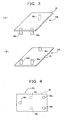
- Respective 3-axis force sensors 36a, 36b, and 36c have the mutually identical makeup, and, as shown in Fig.3(A) and (B) , are made up to protrude downward from a sole.
- respective 3-axis force sensors 36a, 36b, and 36c are allocated, as shown in Fig.4 , at respective tops of an isosceles triangle with a spired rear rim.
- Respective 3-axis force sensors 36a to 36c have data fluctuation for respective detected output, and the detected output varies by the surrounding temperature or ageing. Consequently, the detected outputs of the respective 3-axis force sensors 36a to 36c are automatically calibrated in the compensator 32 by the auto calibration as explained below.
- the calibration in the direction of Z axis.
- n 3-axis force sensors S1, S2, S3, ---, Sn are allocated on a sole with respect to the origin of force measurement O(Ox, Oy).
- the origin of force measurement O is preferably agreed to the drive coordinate system of, for example, the joint of a foot portion.
- the state of three point support is made so that the loads are applied only to said three 3-axis force sensors S1 to S3, and, as shown in Fig.5(B) , arbitrary two 3-axis force sensors among the three, for example, S1 and S2 are connected with a straight line, and the cross point of the perpendicular line from the remaining one 3-axis force sensor S3 to said straight line is assumed as C.
- the center of gravity of the driven object is moved statically along said perpendicular line from S3 to C, and then the voltage values output from S1 to S3 are measured. In this case, the more the measurement points, the more accurate is calibration.
- the calibration parameter for calibration can be calculated.
- arbitrary two 3-axis force sensors for example, S1 and S2 are chosen out of the distributed 3-axis force sensors S1 to Sn, and a robot's upper body 11 or the leg portion of the opposite side 13L or 13R are utilized, and thereby the momentum m around Z axis is generated.
- F1 F2 for the forces F1 and F2 applied on to 3-axis force sensors S1, S2, and momentum m is expressed by the equation below.
- the biped walking robot 10 in accordance with an embodiment of the present invention is made up as described above, and its walking motion is conducted as described below according to the flowchart in Fig.6 .
- respective forces are detected by force detectors 23L, 23R provided on both foot portions 14L, 14R, and are output to the compensator 32.
- the state vector ⁇ of respective joint portions 16L, 16R to 20L, 20R is measured by the angle measurement unit 31, and is output to the compensator 32.
- step ST4 floor reaction force F is calculated by the compensator 32 based on the detected output from the force detectors 23L, 23R.
- the compensator 32 modifies the gait data based on said floor reaction force F and the state vector ⁇ of respective joint portions 16L, 16R to 20L, 20R from the angle measurement unit 31, and outputs ⁇ i to the controller 33.
- said controller 33 subtracts the angle vector ⁇ 0 at a robot's respective joint portion from the vector ⁇ i and forms the control signal of each joint drive motor, that is, torque vector ⁇ , based on the vector ( ⁇ i - ⁇ 0), and outputs it to the motor control unit 34.
- said motor control unit 34 drive-controls the joint drive motors of respective joint portions based on said torque vector ⁇ .
- the biped walking robot 10 conducts walking motion corresponding to the desired motion.
- the gait data is modified in the compensator 32 based on the horizontal floor reaction force F by the detected signal from each 3-axis force sensor 36a, 36b, and 36c of the force detectors 23L, 23R allocated on the sole of each foot portion 14L, 14R, and the vector ⁇ i is formed, thereby a robot 10's stability can be attained with said horizontal floor reaction force F as regulation.
- Fig.7 and Fig.8 illustrate other examples of the makeup of each 3-axis force sensor of force detectors 23L, 23R described above.
- respective 3-axis force sensors 36a, 36b, and 36c are allocated at tops of an equilateral triangle. According to such allocation of 3-axis force sensors 36a, 36b, and 36c, since the loaded weights on respective 3-axis force sensors 36a, 36b, and 36c are uniformly distributed, as well as acting similarly with the 3-axis force sensors 36a to 36c in Fig.4 , the load is reduced on respective 3-axis force sensors 36a, 36b, and 36c.
- respective 3-axis force sensors 36a, 36b, and 36c are allocated at tops of an isosceles triangle like in Fig.4 , as well as on a single periphery with the vertical drive axis O with respect to leg portions 13L, 13R of foot portions 14L, 14R as the center. According to such allocation of 3-axis force sensors 36a, 36b, and 36c, they act similarly with the 3-axis force sensors 36a to 36c in Fig.4 , as well as the torque calibration around said vertical drive axis O can be easily conducted.
- each foot portion 14L, 14R comprises each base portion 14La, 14Ra directly attached to each leg portion 13L, 13R, and a toe portion 14Lb, 14Rb as a finger tip pivotally movably attached vertically to each base portion 14La, 14Ra.
- toe portions 14Lb, 14Rb may be actively pivotable with respect to base portions 14La, 14Ra by drive means like other joint portions, or may be passively pivotable.
- a toe portion 14Lb, 14Rb is provided with a 3-axis force sensor 36d at the position lopsided to the inner side of a tip, and respective 3-axis force sensors 36e, 36f at the positions near both ends of a rear side, while a base portion 14La, 14Ra is provided with one 3-axis force sensor 36g on the heel portion of its rear side.
- the compensator 32 chooses the 3-axis force sensor which detects, for example, larger force based on the detected signal of each 3-axial force sensor 36d to 36g of a force detector 23L, 23R, and modifies the gait data based on the horizontal floor reaction force by three 3-axis force sensors 36d to 36g which detect effective forces.
- the compensator 32 calculates the horizontal floor reaction force based on the detected signals from the above-mentioned three 3-axis force sensors 36e, 36f, and 36g, and modifies the gait data.
- the compensator 32 calculates the horizontal floor reaction force based on the detected signals from the above-mentioned three 3-axis force sensors 36d, 36e, and 36f, and modifies the gait data.
- three 3-axis force sensors 36e, 36f, and 36g, or 36d, 36e, and 36f detect the effective force by receiving the horizontal floor reaction force from the floor surface, and the compensator 32 can accurately modify the gait data.
- 3-axis force sensors 36h, 36i are each allocated at both ends of a tip of the base portion 14La, 14Ra in place of the 3-axis force sensors 36e, 36f allocated at both sides of the rear end of the toe portion 14Lb, 14Rb, and a 3-axis force sensor 36d of a tip of the toe portion 14Lb, 14Rb is allocated at about a center with respect to the left and right direction.
- 3-axis force sensors 36h, 36i are allocated at each top of an isosceles triangle with respect to a 3-axis force sensor 36d or 36g.
- 3-axis force sensors 36d, 36h, 36i and 36g act similarly with the 3-axis force sensors 36d to 36g in Fig.9 , and can conduct calibration easily for the middle 3-axis force sensors 36h, 36i, and further, can be more firmly attached to foot portions 14L, 14R by being attached to the base portions 14La, 14Ra which is larger than toe portions 14Lb, 14Rb.
- the middle 3-axis force sensors 36h, 36i are each provided to both sides of the tip of base portions 14La, 14Ra, but, not limited to this case, may be provided to the connecting region of base portions 14La, 14Ra and toe portions 14Lb, 14Rb.
- respective 3-axis force sensors 36a to 36c, or 36d to 36g, or 36d, 36h, 36i, and 36g of force detectors 23L, 23R provided on the soles of respective foot portions 14L, 14R firmly land on to the road surface with complex roughness. Consequently, by modifying gait data based on the horizontal floor reaction force F calculated from the detected signal from each 3-axis force sensor, walk control can be conducted with the horizontal floor reaction force F generated from the friction of a sole with the floor surface as regulation, and the walk stabilization of the robot 10 can be achieved in the unstable road surface state with complex roughness.
- 3-axis force sensors are allocated symmetrically left and right, but, not limited as such, it may be obviously an allowable case to be allocated at the tops of an inequilateral triangle.
- 3-axis force sensors are allocated on the bottom side of a plate which makes up each sole, but, not limited as such, it may also be an allowable case that other plate is attached to the lower part of a 3-axis force sensor, and said 3-axis force sensor is inserted between said plates. In this case, said 3-axis force sensor can detect not only compressing force but also pulling force.
- each 3-axis force sensor for example, is allocated in even position on a sole, respectively, with respect to the directions back and forth and left and right, force amplification and calibration are easily conducted, as well as a sensor can be most efficiently used.
- the force detector 23L, 23R is provided with three 3-axis force sensor 36a, 36b, and 36c, respectively, and in Fig.9 and Fig.11 , always three 3-axis force sensors 36d, 36e (36h), 36f (36i), or 36e (36h), 36f (36i), 36g of the force detector 23L, 23R land on the floor surface, but not limited as such, three or more 3-axis force sensors may be provided, respectively.
- two 3-axis force sensors 36j, 36k may be provided in the middle region.
- the compensator 32 compares the detected signals of respective 3-axis force sensors 36a, 36b, 36c, 36j, and 36k, and chooses three 3-axis force sensors which detect larger force, and may calculate the horizontal floor reaction force from the chosen three 3-axis force sensors.
- a compensator 32 modifies the gait data with the horizontal floor reaction force as regulation based on the detected signals from respective 3-axis force sensors of the force detectors 23L, 23R, but not limited as such, it may be obviously an allowable case to modify the gait data with ZMP regulation based on the detected signals from respective 3-axis force sensors of force detectors 23L, 23R, as were the past cases. Further in the above-mentioned embodiment, explanation was given to the case where the present invention is applied to a biped walking robot, but not limited as such, it is obvious that the present invention is applicable to a biped walking mobile system in which other various machines are supported on two legs, and said two legs make it possible to walk.
- a quite excellent biped walking mobile system and a walk control system therfor are provided, which can realize the walk stability by accurately detecting the floor reaction force on soles of a robot, even in the unstable road surface condition with complex roughness.
Landscapes
- Engineering & Computer Science (AREA)
- Mechanical Engineering (AREA)
- Robotics (AREA)
- Chemical & Material Sciences (AREA)
- Combustion & Propulsion (AREA)
- Transportation (AREA)
- Human Computer Interaction (AREA)
- Manipulator (AREA)
Abstract
A walk controller(30) for a biped (two-footed) walking mobile system, which drive-controls each joint drive motor (15L, 15R - 20L, 20R) of each leg portion (13L, 13R) of a biped walking mobile system based on gait data, includes a force detector (23L, 23R) to detect the force allied to a sole of each foot portion (14L, 14R), and a compensator (32) to modify the gait data from a gait former (24) based on the force detected by a force detector, and is constituted so that each force detector (23L, 23R) comprises at least three 3-axial force sensors (36a, 36b, 36c) allocated on a sole of each foot portion (14L, 14R), and a compensator (32) modifies gait data based on the detected signals from three 3-axial force sensors (36a, 36b, 36c) which detect effective force, thereby the walk stability of a robot is realized, even on the unstable road surface condition with complex roughness.
Description
- The present invention relates to a biped (two-footed) walking mobile system, and more specifically to its walk control system which leads to stable walking.
- A conventional biped walking robot generates the pre-designed walk pattern (hereinafter to be called "gait") data, conducts walk control according to said gait data, moves foot portions by the predetermined walk pattern, and thereby realizes biped walking.
However, such a biped walking robot tends to be unstable in walking posture upon walking due, for example, to road surface conditions, or the error of the robot's own physical parameters, or else, and may tumble down in some cases. On the other hand, if a robot is made to conduct walk control without pre-designed gait data while confirming walk conditions in real time, then walking is possible with stable walking posture, but even in such cases, the robot may tumble down with collapsed walking posture, when unexpected road conditions are encountered. - Therefore, what is called ZMP compensation is required, whereby the points on the sole of a foot of the robot where the composite momentum of floor reaction force and gravity becomes zero (hereinafter to be called ZMP "Zero Moment Point") are converged to the target value. As such a control method for ZMP compensation, the method to accelerate and adjust the robot's upper body by utilizing compliance control and converging ZMP to the target value, as shown, for example, in
JP 5-305583 A
Incidentally, in such control methods, the stabilization of a robot is aimed by ZMP regulation, and in said ZMP regulation there should be a prerequisite to accurately detect floor reaction force at a sole. - However, as for a biped walking robot of such structure, there may be such cases where a whole sole does not land on the road surface in the unstable road condition with complex roughness, and floor reaction force at a sole can not be accurately detected, and thereby ZMP compensation can not be accurately conducted. For this reason, the robot's stability can not be maintained, and the robot's biped walking becomes difficult.
Known fromEP 1 464 451 A1claim 1. - It is the object of the present invention, taking into consideration the above-mentioned problems, to provide a walk controller for a biped walking mobile system to realize walk stability by accurately detecting floor reaction force at a sole in the unstable road condition with complex roughness.
- The above-mentioned objective is achieved in accordance with the walk controller according to
claim 1.
A walk control system of a biped walking mobile system in accordance with the present invention is preferably such that said compensator automatically calibrates the detected signals from each 3-axial force sensor by autocalibration. - According to said aspect, a drive means is drive-controlled by modifying by a compensator the gait data from a gait former based on the force detected by a force detector comprising at least three 3-axial force sensor allocated on a sole of each foot portion. In that case, when a foot portion lands on the road surface with complex roughness, the three 3-axial force sensors protruding downward from a sole steadily contact the road surface. Therefore, the stabilization of a main body, for example, a humanoid robot's upper body can be maintained by accurately modifying the gait data based on the detected signal from three 3-axial force sensors which detect effective force even on unstable road surface. Accordingly, even on unstable road surface with complex roughness, a sole of each foot portion of a robot can maintain the stability of a robot, and make possible steady walk control.
In case that three 3-axial force sensors are allocated at three tops of an isosceles triangle on a sole of respective foot portion, two of the 3-axial force sensors at the both ends of the bottom side of an isosceles triangle are in symmetrical condition, therefore the weight loaded on each 3-axial force sensor can be distributed evenly on left and right, and each 3-axial force sensor can be easily calibrated.
In case that each 3-axial force sensor is allocated on a periphery of a circle with the center on the vertical drive axis of a foot portion on a sole of respective foot portion, the torques around said vertical drive axis are in the same condition, therefore the loads with respect to said torques can be evenly distributed to each 3-axial force sensor, and each 3-axial force sensor can be easily calibrated with respect to the torques. - In case that each foot portion comprises an base portion attached directly to the lower end of a leg portion, and a toe portion as a finger tip attached pivotally movably vertically to the end of said base portion, and each 3-axial force sensor of a force detector is distributed on an base portion and a toe portion, when only an base portion or a toe portion is in contact with the ground, each 3-axial force sensor of a force detector can detect the floor reaction force on a sole.
In case that one of the 3-axial force sensors is allocated near an base portion, and another 3-axial force sensor is allocated near the tip of a toe portion, and still two other 3-axial force sensors are allocated left and right in the region near the border of an base portion and a toe portion, when only an base portion or a toe portion is in contact with the ground, three 3-axial force sensors of a force detector are in contact with the ground, and can accurately detect the floor reaction force on a sole.
In case that said compensator automatically calibrates the detected signals from each 3-axial force sensor by autocalibration, even if the detection accuracy is changed in respective 3-axial force sensor of a force detector due to the surrounding temperature or ageing, autocalibration is conducted, and the floor reaction force can be accurately detected by the detected signals from each 3-axial force sensor of a force detector. - The present invention will better be understood from the following detailed description and the drawings attached hereto showing certain illustrative forms of embodiment of the present invention. In this connection, it should be noted that such forms of embodiment illustrated in the accompanying drawings hereof are intended in no way to limit the present invention but to facilitate an explanation and an understanding thereof, in which drawings:
-
Fig.1 is a schematic view illustrating the mechanical makeup of a biped walking robot according to the present invention as one form of embodiment thereof; -
Fig.2 is a block diagram illustrating the electrical makeup of a biped walking robot shown inFig.1 ; -
Fig.3 illustrates the allocation of a 3-axis force sensor allocated on a sole of each foot portion of a biped walking robot shown inFig.1 , and (A) is the brief perspective view seen diagonally from the upper side, and (B) is the brief perspective view seen diagonally from the lower side; -
Fig.4 is a plan view of a sole illustrating the allocation of 3-axis force sensors shown inFig.3 ; -
Fig.5 is a graph illustrating the allocation of each 3-axis force sensor and the base position of force measurement shown inFig.4 ; -
Fig.6 is a flowchart illustrating the walk control motion of a biped walking robot shown inFig.1 ; -
Fig.7 is a plan view of a sole illustrating the first modified example of the allocation of a 3-axis force sensor shown in Fig.3(C); -
Fig.8 is a plan view of a sole illustrating the second modified example of the allocation of a 3-axis force sensor shown in Fig.3(C); -
Fig.9 illustrates the third modified example of the allocation of a 3-axial force sensor shown in Fig.3(C), and (A)is a side view of a foot portion, and (B) is a plan view of a sole; -
Fig.10 is, in case of landing at a toe portion in a modified example shown inFig.9 , and (A) is a side view of a foot portion, and (B) is a plan view of a sole;
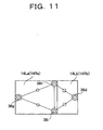
Fig.11 is a plan view of a sole illustrating the fourth modified example of the allocation of a 3-axis force sensor shown in Fig.3(C). - Hereinafter, the present invention will be described in detail with reference to suitable forms of embodiment thereof illustrated in the figures.
Fig.1 andFig.2 show the makeup of an embodiment of a biped walking robot with a biped walking mobile system applied thereto in accordance with the present invention. Referring toFig.1 , a bipedwalking robot 10 includes anupper body 11 as a main body having at both sides of its lower part a pair ofleg portions knee portion 12L, 12R in its midway, and afoot portion - Here, each of said
leg portions joint portion upper body 11, thejoint portion joint portion joint portion knee portion 12L, 12R, thejoint portion foot portion joint portion joint portion joint portions joint portions - Further between a waist and a knee joints, they are connected with the
thigh links lower thigh links leg portions foot portions walking robot 10 have six degrees of freedom, respectively, and it is so made up to be capable of walking at will in a three dimensional space by drive-controlling these twelve joint portions during walk with respective drive motors at appropriate angles, and by giving desired motions towhole leg portions foot portions foot portions force detectors force detectors respective foot portions upper body 11 is illustrated like a mere box, but actually it may be provided with a head portion or two hands. -
Fig.2 illustrates the electrical makeup of a bipedwalking robot 10 shown inFig.1 . InFig.2 , a bipedwalking robot 10 is provided with a gait former 24 to form a gait data corresponding to the desired motion, and awalk controller 30 to drive-control the drive means, that is, thejoint drive motors
Here, xyz coordinate system is used as that for abiped walking robot 10 with x direction as anteroposterior direction ( forward as +), with y direction as horizontal direction ( inner direction as +), and with z direction as vertical direction ( upper direction as +). - Said gait former 24 is to form the gait data including the target angle orbital, target angle velocity, and target angle acceleration of respective
joint portions walking robot 10, based on the desired motion input from outside.
Saidwalk controller 30 is made up with anangle measurement unit 31, acompensator 32, acontroller 33, and amotor control unit 34. - Into said
angle measurement unit 31, the angle information of the respective joint drive motor is input by, for example, a rotary encoder or else, provided in the joint drive motor of respectivejoint portion compensator 32. Saidcompensator 32 calculates the floor reaction force F based on the detected output from aforce detector angle measurement unit 31, and outputs the vector θ i ( i =1 to n, where n is the degree of freedom with respect to arobot 10's walk) to thecontroller 33. Here, saidcontroller 33 subtracts the angle vector θ 0 at a robot's respective joint portion from the vector θ i as the gait data modified by thecompensator 32, and forms the control signal of each joint drive motor, that is, torque vector τ, based on the vector (θ i - θ 0). Further, saidmotor control unit 34 drive-controls each joint drive motor according to the control signal from the controller 33 ( torque vector τ). - Here, since said
force detectors force detector 23L only referring toFig.3 . InFig.3 , theforce detector 23L is made up, on the bottom side of asole plate 35 as the lower face of thefoot portion 14L, of three 3-axis force sensors
Respective 3-axis force sensors Fig.3(A) and (B) , are made up to protrude downward from a sole. Further, respective 3-axis force sensors Fig.4 , at respective tops of an isosceles triangle with a spired rear rim. - Respective 3-
axis force sensors 36a to 36c have data fluctuation for respective detected output, and the detected output varies by the surrounding temperature or ageing. Consequently, the detected outputs of the respective 3-axis force sensors 36a to 36c are automatically calibrated in thecompensator 32 by the auto calibration as explained below.
First of all, explanation will be given to the calibration in the direction of Z axis.
InFig.5(A) , n 3-axis force sensors S1, S2, S3, ---, Sn are allocated on a sole with respect to the origin of force measurement O(Ox, Oy). The origin of force measurement O is preferably agreed to the drive coordinate system of, for example, the joint of a foot portion. Here, the position of respective 3-axis force sensor Si is assumed as Si = (X(i), Y(i)), and arbitrary three 3-axis force sensors, for example, S1, S2, and S3 are chosen out of the 3-axial force sensors S1 to Sn distributed as mentioned above, and their coordinate positions are respectively assumed as S1=X(1), Y(1), Z(1), S2=X(2), Y(2), Z(2), S3=X(3), Y(3), Z(3).
The state of three point support is made so that the loads are applied only to said three 3-axis force sensors S1 to S3, and, as shown inFig.5(B) , arbitrary two 3-axis force sensors among the three, for example, S1 and S2 are connected with a straight line, and the cross point of the perpendicular line from the remaining one 3-axis force sensor S3 to said straight line is assumed as C.
Here, the center of gravity of the driven object is moved statically along said perpendicular line from S3 to C, and then the voltage values output from S1 to S3 are measured. In this case, the more the measurement points, the more accurate is calibration. - Assume f as the measured force, A,B as calibration parameters, V as the voltage value at that instant, M as the total mass of the driven object, g as the acceleration of gravity, and k as the measurement point, then the relating equations are obtained.


- Further, the method of calibration with respect to X and Y axes will be explained.
First, as shown inFig.5(C) , arbitrary two 3-axis force sensors, for example, S1 and S2 are chosen out of the distributed 3-axis force sensors S1 to Sn, and a robot'supper body 11 or the leg portion of theopposite side 
Consequently, forces F1, F2 applied on to individual 3-axis force sensors S1, S2 are calculated, and the respective X and Y components are expressed by the equation below.
- On the other hand, the relationship between the voltage value V output from respective 3-axis force sensors S1, S2 and the forces fx, fy is expressed by the equations below, with k as the number of measurement.
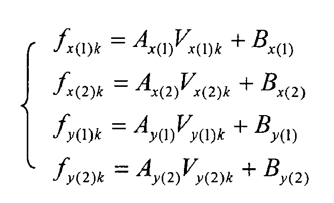
With these equation combined, and by measurements of n times, the determinants as shown below is obtained, and the calibration parameters A, B can be calculated.

Thus, by simultaneously calculating the calibration parameters A, B in the directions of X and Y axes, calibration can be made in the XY axis directions.
Incidentally for the above-mentioned calibration, when respective 3-axis force sensors 36a to 36c are allocated at the tops of an isosceles triangle as shown inFig.4 , the calibration parameters by calibration have the same value, since the 3-axis force sensors - The
biped walking robot 10 in accordance with an embodiment of the present invention is made up as described above, and its walking motion is conducted as described below according to the flowchart inFig.6 .
InFig.6 , first of all by the step ST1, the gait data is formed by the gait former 24 based on the desired motion (J=J) which is input, and then is output to thecompensator 32 of thewalk controller 30. And by the step ST2, respective forces are detected byforce detectors foot portions compensator 32. Also by the step ST3, the state vector φ of respectivejoint portions angle measurement unit 31, and is output to thecompensator 32. By the step ST4 which follows, floor reaction force F is calculated by thecompensator 32 based on the detected output from theforce detectors compensator 32 modifies the gait data based on said floor reaction force F and the state vector φ of respectivejoint portions angle measurement unit 31, and outputs θ i to thecontroller 33.
Next by the step ST6, saidcontroller 33 subtracts the angle vector θ 0 at a robot's respective joint portion from the vector θ i and forms the control signal of each joint drive motor, that is, torque vector τ, based on the vector ( θ i - θ 0), and outputs it to themotor control unit 34. And by the step ST7, saidmotor control unit 34 drive-controls the joint drive motors of respective joint portions based on said torque vector τ. As a result, thebiped walking robot 10 conducts walking motion corresponding to the desired motion.
After that, by the step ST8, thecontroller 33 makes J=J+1 by motion counter increment, and waits for the pre-set sampling time, thereafter by the step ST9, if said J is below the pre-set motion finishing count, then the step is returned to ST2, and the above-mentioned motion is repeated. And at the step ST9, if said J exceeds the motion finishing count, then the motion is stopped. - In this case, for the
biped walking robot 10 to drive-control each joint drive motor, the gait data is modified in thecompensator 32 based on the horizontal floor reaction force F by the detected signal from each 3-axis force sensor force detectors foot portion robot 10's stability can be attained with said horizontal floor reaction force F as regulation. Accordingly, even if arobot 10's eachfoot portion axis force sensor force detector -
Fig.7 and Fig.8 illustrate other examples of the makeup of each 3-axis force sensor offorce detectors
First inFig.7 , respective 3-axis force sensors axis force sensors axis force sensors axis force sensors 36a to 36c inFig.4 , the load is reduced on respective 3-axis force sensors
InFig.8 , respective 3-axis force sensors Fig.4 , as well as on a single periphery with the vertical drive axis O with respect toleg portions foot portions axis force sensors axis force sensors 36a to 36c inFig.4 , as well as the torque calibration around said vertical drive axis O can be easily conducted. -
Fig.9 to Fig.11 illustrate still other examples of the makeup of each 3-axis force sensor offorce detectors foot portion leg portion
InFig.9 , a toe portion 14Lb, 14Rb is provided with a 3-axis force sensor 36d at the position lopsided to the inner side of a tip, and respective 3-axis force sensors axis force sensor 36g on the heel portion of its rear side. - On the other hand, the
compensator 32 chooses the 3-axis force sensor which detects, for example, larger force based on the detected signal of each 3-axial force sensor 36d to 36g of aforce detector axis force sensors 36d to 36g which detect effective forces.
According to such allocation of 3-axis force sensors foot portion Fig.9(A) , three 3-axis force sensors axial force sensors axis force sensor 36g allocated on the rear side of the base portion 14La, 14Ra, contact the floor surface, bear the loaded weight as shown with the hatched line inFig.9(B) , and the horizontal floor reaction force is applied from the floor surface. Therefore, thecompensator 32 calculates the horizontal floor reaction force based on the detected signals from the above-mentioned three 3-axis force sensors - On the other hand, in case that only the toe portion 14Lb, 14Rb of the
foot portion Fig.10(A) , three 3-axis force sensors Fig.10(B) , and the horizontal floor reaction force is applied from the floor surface.
Therefore, thecompensator 32 calculates the horizontal floor reaction force based on the detected signals from the above-mentioned three 3-axis force sensors foot portion axis force sensors compensator 32 can accurately modify the gait data. - In
Fig.11 , as for each 3-axis force sensor 36d to 36g, by comparison with the case ofFig.9 , 3-axis force sensors axis force sensors axis force sensor 36d of a tip of the toe portion 14Lb, 14Rb is allocated at about a center with respect to the left and right direction. Thus, 3-axis force sensors axis force sensor
According to such allocation of 3-axis force sensors axis force sensors 36d to 36g inFig.9 , and can conduct calibration easily for the middle 3-axis force sensors foot portions
Here inFig.11 , the middle 3-axis force sensors - Thus in case of the
biped walking robot 10 according to the embodiment of the present invention, respective 3-axis force sensors 36a to 36c, or 36d to 36g, or 36d, 36h, 36i, and 36g offorce detectors respective foot portions robot 10 can be achieved in the unstable road surface state with complex roughness. - In the above-mentioned embodiment, for example, in
Fig.4 ,Fig.7 ,Fig.8 ,Fig.9 ,andFig.11 , 3-axis force sensors are allocated symmetrically left and right, but, not limited as such, it may be obviously an allowable case to be allocated at the tops of an inequilateral triangle. Also in the above-mentioned embodiment, 3-axis force sensors are allocated on the bottom side of a plate which makes up each sole, but, not limited as such, it may also be an allowable case that other plate is attached to the lower part of a 3-axis force sensor, and said 3-axis force sensor is inserted between said plates. In this case, said 3-axis force sensor can detect not only compressing force but also pulling force.
Here in such a sensor structure, if each 3-axis force sensor, for example, is allocated in even position on a sole, respectively, with respect to the directions back and forth and left and right, force amplification and calibration are easily conducted, as well as a sensor can be most efficiently used. - Also in the above-mentioned embodiment, for example, in
Fig.4 ,Fig.7, and Fig.8 , theforce detector axis force sensor Fig.9 andFig.11 , always three 3-axis force sensors force detector Fig.4 , two 3-axis force sensors 36j, 36k may be provided in the middle region. In this case, thecompensator 32 compares the detected signals of respective 3-axis force sensors - Further in the above-mentioned embodiment, a
compensator 32 modifies the gait data with the horizontal floor reaction force as regulation based on the detected signals from respective 3-axis force sensors of theforce detectors force detectors
Further in the above-mentioned embodiment, explanation was given to the case where the present invention is applied to a biped walking robot, but not limited as such, it is obvious that the present invention is applicable to a biped walking mobile system in which other various machines are supported on two legs, and said two legs make it possible to walk. - According to the present invention as described above, a quite excellent biped walking mobile system and a walk control system therfor are provided, which can realize the walk stability by accurately detecting the floor reaction force on soles of a robot, even in the unstable road surface condition with complex roughness.
Claims (2)
- A walk controller (30) for a biped walking mobile system (1) to drive-control drive means (15L, 15R to 20L, 20R) based on a gait data including target angle orbital, target angle velocity, and target angle acceleration formed by a gait former (24) corresponding to the required motion, wherein the biped walking mobile system (1) comprises a main body (11), a pair of leg portions (13L, 13R) attached thereto at both sides of its lower part so as to be each pivotally movable biaxially, each of the leg portions (13L, 13R) having a knee portion (12L, 12R) in its midway and a foot portion (14L, 14R) at its lower end, the foot portions (14L, 14R) being attached to their corresponding leg portions (13L, 13R) so as to be pivotally movable biaxially, the drive means (15L, 15R to 20L, 20R) pivotally moving each leg, knee, and foot portion (13L, 13R; 12L, 12R; 14L, 14R),
the walk controller (30) comprising:a force detector (23L, 23R) to detect the force applied on a sole of each foot portion (14L, 14R), anda compensator (32) to modify the gait data from the gait former (24) based on the force detected by said force detector (23L, 23R),wherein said force detector (23L, 23R) comprises four 3-axis force sensors (36d to 36g; 36d, 36g, 36h, 36i) allocated on the sole of each foot portion (14L, 14R),characterized in thateach 3-axis force sensor (36d to 36g; 36d, 36g, 36h, 36i) protrudes downward from a sole,the compensator (32) is adapted to select the three 3-axis force sensors (36d to 36g; 36d, 36g, 36h, 36i) which detect effective forces. - The walk controller (30) for a biped walking mobile system (1) as set forth in claim 1, characterized in that, said compensator (32) automatically calibrates the detected signal from each 3-axis force sensor (36e, 36f; 36h, 36i) by auto calibration.
Applications Claiming Priority (2)
| Application Number | Priority Date | Filing Date | Title |
|---|---|---|---|
| JP2002040837A JP3574952B2 (en) | 2002-02-18 | 2002-02-18 | Bipod walking type moving device and its walking control device |
| EP03703262A EP1477283A4 (en) | 2002-02-18 | 2003-02-07 | LOCOMOTIVE DEVICE MOVING ON TWO LEGS AND ASSOCIATED CONTROL ORDER |
Related Parent Applications (1)
| Application Number | Title | Priority Date | Filing Date |
|---|---|---|---|
| EP03703262.0 Division | 2003-02-07 |
Publications (1)
| Publication Number | Publication Date |
|---|---|
| EP2208583A1 true EP2208583A1 (en) | 2010-07-21 |
Family
ID=27678321
Family Applications (2)
| Application Number | Title | Priority Date | Filing Date |
|---|---|---|---|
| EP03703262A Withdrawn EP1477283A4 (en) | 2002-02-18 | 2003-02-07 | LOCOMOTIVE DEVICE MOVING ON TWO LEGS AND ASSOCIATED CONTROL ORDER |
| EP10003900A Withdrawn EP2208583A1 (en) | 2002-02-18 | 2003-02-07 | Walk control system for a biped walking mobile system |
Family Applications Before (1)
| Application Number | Title | Priority Date | Filing Date |
|---|---|---|---|
| EP03703262A Withdrawn EP1477283A4 (en) | 2002-02-18 | 2003-02-07 | LOCOMOTIVE DEVICE MOVING ON TWO LEGS AND ASSOCIATED CONTROL ORDER |
Country Status (7)
| Country | Link |
|---|---|
| US (1) | US6992457B2 (en) |
| EP (2) | EP1477283A4 (en) |
| JP (1) | JP3574952B2 (en) |
| KR (1) | KR100581372B1 (en) |
| CN (1) | CN100336633C (en) |
| TW (1) | TW586994B (en) |
| WO (1) | WO2003068462A1 (en) |
Cited By (1)
| Publication number | Priority date | Publication date | Assignee | Title |
|---|---|---|---|---|
| WO2018051365A1 (en) * | 2016-09-16 | 2018-03-22 | Vaish Diwakar | A robotic foot having a toe actuation mechanism for a humanoid robot and method for constructing thereof |
Families Citing this family (38)
| Publication number | Priority date | Publication date | Assignee | Title |
|---|---|---|---|---|
| JP3574951B2 (en) * | 2001-12-19 | 2004-10-06 | 独立行政法人 科学技術振興機構 | Biped walking type moving device, its walking control device and walking control method |
| KR100835361B1 (en) * | 2003-08-29 | 2008-06-04 | 삼성전자주식회사 | Walking Robot Using Simple Ground Reaction Sensor and Its Control Method |
| JP4744092B2 (en) | 2004-03-23 | 2011-08-10 | 本田技研工業株式会社 | Legged mobile robot and its control device |
| CN1946521A (en) * | 2004-07-30 | 2007-04-11 | 提姆查克股份有限公司 | Multi-point landing type foot support mechanism, biped walking robot equipped with the mechanism, and its control structure |
| JP2006068872A (en) * | 2004-09-03 | 2006-03-16 | Honda Motor Co Ltd | Legged mobile robot |
| CN101068663B (en) * | 2004-12-14 | 2010-11-17 | 本田技研工业株式会社 | Legged mobile robot and control method thereof |
| JP4506512B2 (en) * | 2005-03-07 | 2010-07-21 | トヨタ自動車株式会社 | Offset adjustment system and offset adjustment method for walking robot with supporting legs |
| JP4456560B2 (en) * | 2005-12-12 | 2010-04-28 | 本田技研工業株式会社 | Legged mobile robot control device, legged mobile robot, and legged mobile robot control method |
| JP4877668B2 (en) * | 2006-06-07 | 2012-02-15 | 有限会社ケイテックシステム | Standing balance measuring device |
| JP4539618B2 (en) * | 2006-07-31 | 2010-09-08 | トヨタ自動車株式会社 | Legged robot |
| JP4466715B2 (en) | 2007-10-25 | 2010-05-26 | トヨタ自動車株式会社 | Legged robot and control method thereof |
| JP5322147B2 (en) * | 2007-11-06 | 2013-10-23 | 学校法人立命館 | Foot mechanism of multi-legged walking device |
| US7905303B2 (en) * | 2009-02-10 | 2011-03-15 | Honda Motor Co., Ltd. | Legged locomotion robot |
| JP5232124B2 (en) * | 2009-10-28 | 2013-07-10 | 本田技研工業株式会社 | Control device for legged mobile robot |
| JP5483997B2 (en) * | 2009-10-28 | 2014-05-07 | 本田技研工業株式会社 | Control device for legged mobile robot |
| KR101633362B1 (en) * | 2010-01-18 | 2016-06-28 | 삼성전자 주식회사 | Humanoid robot and walking control method thereof |
| KR101772972B1 (en) * | 2010-12-22 | 2017-09-01 | 삼성전자주식회사 | Walking robot and control method thereof |
| JP5659898B2 (en) * | 2011-03-22 | 2015-01-28 | トヨタ自動車株式会社 | Legged robot, its control method, and control program |
| CN102658548A (en) * | 2012-05-04 | 2012-09-12 | 北京理工大学 | Waist movement planning method and device for preventing humanoid robot from tilting back and forth |
| KR101383726B1 (en) * | 2012-12-17 | 2014-04-08 | 현대자동차(주) | Method for improving sensitivity of robot |
| JP2015071214A (en) * | 2013-10-04 | 2015-04-16 | キヤノン株式会社 | Force sensor protection mechanism, end effector and robot arm |
| US10081098B1 (en) | 2014-08-25 | 2018-09-25 | Boston Dynamics, Inc. | Generalized coordinate surrogates for integrated estimation and control |
| US9618937B1 (en) | 2014-08-25 | 2017-04-11 | Google Inc. | Slip detection using robotic limbs |
| US9387588B1 (en) | 2014-08-25 | 2016-07-12 | Google Inc. | Handling gait disturbances with asynchronous timing |
| US9446518B1 (en) | 2014-11-11 | 2016-09-20 | Google Inc. | Leg collision avoidance in a robotic device |
| US9499218B1 (en) | 2014-12-30 | 2016-11-22 | Google Inc. | Mechanically-timed footsteps for a robotic device |
| CN104709374B (en) * | 2015-02-13 | 2017-03-08 | 中国北方车辆研究所 | A kind of method preventing legged type robot from tilting |
| US9594377B1 (en) | 2015-05-12 | 2017-03-14 | Google Inc. | Auto-height swing adjustment |
| US9586316B1 (en) | 2015-09-15 | 2017-03-07 | Google Inc. | Determination of robotic step path |
| US9994269B1 (en) * | 2015-11-12 | 2018-06-12 | Schaft Inc. | Rotatable extension for robot foot |
| US9778132B1 (en) | 2015-12-16 | 2017-10-03 | X Development Llc | Methods and systems for force sensor calibration |
| US9925667B1 (en) | 2016-01-25 | 2018-03-27 | Boston Dynamics, Inc. | Continuous slip recovery |
| US9789919B1 (en) | 2016-03-22 | 2017-10-17 | Google Inc. | Mitigating sensor noise in legged robots |
| CN105619392B (en) * | 2016-03-29 | 2017-06-23 | 刘子骞 | The robot and its control method of a kind of balance quality stabilization |
| JP7065369B2 (en) * | 2017-10-13 | 2022-05-12 | パナソニックIpマネジメント株式会社 | Assist device, operation method and program of assist device |
| CN110340880A (en) * | 2018-04-02 | 2019-10-18 | 新世代机器人暨人工智慧股份有限公司 | Variable attitude robot and its attitude adjustment method |
| JP7046110B2 (en) * | 2020-02-21 | 2022-04-01 | 株式会社ソニー・インタラクティブエンタテインメント | Sensor control device, sensor control method and program |
| CN114872814B (en) * | 2022-04-15 | 2024-12-31 | 上海师范大学 | A bionic biped robot and its stable gait planning method |
Citations (3)
| Publication number | Priority date | Publication date | Assignee | Title |
|---|---|---|---|---|
| JPH05305583A (en) | 1992-04-30 | 1993-11-19 | Honda Motor Co Ltd | Walking control device for leg type mobile robot |
| US5974366A (en) * | 1996-12-18 | 1999-10-26 | Honda Giken Kogyo Kabushiki Kaisha | Apparatus for detecting the landing position of foot sole of legged moving robot |
| EP1081027A2 (en) * | 1999-08-30 | 2001-03-07 | Honda Giken Kogyo Kabushiki Kaisha | Legged mobile robot |
Family Cites Families (17)
| Publication number | Priority date | Publication date | Assignee | Title |
|---|---|---|---|---|
| JP2520019B2 (en) * | 1989-06-29 | 1996-07-31 | 本田技研工業株式会社 | Drive controller for legged mobile robot |
| JP2592340B2 (en) * | 1989-12-14 | 1997-03-19 | 本田技研工業株式会社 | Joint structure of a legged walking robot |
| JP2826858B2 (en) * | 1989-12-14 | 1998-11-18 | 本田技研工業株式会社 | Leg structure of a legged walking robot |
| US5255753A (en) * | 1989-12-14 | 1993-10-26 | Honda Giken Kogyo Kabushiki Kaisha | Foot structure for legged walking robot |
| US5455497A (en) * | 1992-04-20 | 1995-10-03 | Honda Giken Kogyo Kabushiki Kaisha | Legged mobile robot and a system for controlling the same |
| JP3132156B2 (en) * | 1992-05-22 | 2001-02-05 | 本田技研工業株式会社 | Gait generator for legged mobile robot |
| JP3269852B2 (en) * | 1992-05-29 | 2002-04-02 | 本田技研工業株式会社 | Posture stabilization control device for legged mobile robot |
| JPH09212203A (en) * | 1995-11-30 | 1997-08-15 | Sony Corp | Robot controller |
| JP3672406B2 (en) * | 1997-01-31 | 2005-07-20 | 本田技研工業株式会社 | Gait generator for legged mobile robot |
| JPH11160150A (en) | 1997-11-28 | 1999-06-18 | Toshiba Corp | Displacement detector |
| DE69943148D1 (en) * | 1998-04-20 | 2011-03-03 | Honda Motor Co Ltd | CONTROL UNIT FOR A LEG ROBOT |
| JP3400377B2 (en) * | 1999-03-10 | 2003-04-28 | 富士通株式会社 | Foot sensor and humanoid robot having the same |
| JP3555107B2 (en) * | 1999-11-24 | 2004-08-18 | ソニー株式会社 | Legged mobile robot and operation control method for legged mobile robot |
| JP4480843B2 (en) | 2000-04-03 | 2010-06-16 | ソニー株式会社 | Legged mobile robot, control method therefor, and relative movement measurement sensor for legged mobile robot |
| JP3634238B2 (en) * | 2000-05-19 | 2005-03-30 | 本田技研工業株式会社 | Floor shape estimation device for legged mobile robot |
| US6789338B2 (en) * | 2000-11-17 | 2004-09-14 | Honda Giken Kogyo Kabushiki Kaisha | Remote controller of biped robot |
| JP3760186B2 (en) | 2001-06-07 | 2006-03-29 | 独立行政法人科学技術振興機構 | Biped walking type moving device, walking control device thereof, and walking control method |
-
2002
- 2002-02-18 JP JP2002040837A patent/JP3574952B2/en not_active Expired - Fee Related
-
2003
- 2003-02-07 EP EP03703262A patent/EP1477283A4/en not_active Withdrawn
- 2003-02-07 KR KR1020047012584A patent/KR100581372B1/en not_active Expired - Fee Related
- 2003-02-07 US US10/504,691 patent/US6992457B2/en not_active Expired - Fee Related
- 2003-02-07 CN CNB038040840A patent/CN100336633C/en not_active Expired - Fee Related
- 2003-02-07 EP EP10003900A patent/EP2208583A1/en not_active Withdrawn
- 2003-02-07 WO PCT/JP2003/001324 patent/WO2003068462A1/en not_active Ceased
- 2003-02-14 TW TW092103046A patent/TW586994B/en not_active IP Right Cessation
Patent Citations (3)
| Publication number | Priority date | Publication date | Assignee | Title |
|---|---|---|---|---|
| JPH05305583A (en) | 1992-04-30 | 1993-11-19 | Honda Motor Co Ltd | Walking control device for leg type mobile robot |
| US5974366A (en) * | 1996-12-18 | 1999-10-26 | Honda Giken Kogyo Kabushiki Kaisha | Apparatus for detecting the landing position of foot sole of legged moving robot |
| EP1081027A2 (en) * | 1999-08-30 | 2001-03-07 | Honda Giken Kogyo Kabushiki Kaisha | Legged mobile robot |
Non-Patent Citations (2)
| Title |
|---|
| KAJITA S ET AL: "Adaptive gait control of a biped robot based on realtime sensing of the ground profile", ROBOTICS AND AUTOMATION, 1996. PROCEEDINGS., 1996 IEEE INTERNATIONAL CONFERENCE ON MINNEAPOLIS, MN, USA 22-28 APRIL 1996, NEW YORK, NY, USA,IEEE, US, vol. 1, 22 April 1996 (1996-04-22), pages 570 - 577, XP010162810, ISBN: 0-7803-2988-0 * |
| KAJITA S ET AL: "ADAPTIVE GAIT CONTROL OF A BIPED ROBOT BASED ON REALTIME SENSING OFTHE GROUND PROFILE", AUTONOMOUS ROBOTS, KLUWER ACADEMIC PUBLISHERS, DORDRECHT, NL, vol. 4, no. 3, 1997, pages 297 - 305, XP000659961, ISSN: 0929-5593 * |
Cited By (1)
| Publication number | Priority date | Publication date | Assignee | Title |
|---|---|---|---|---|
| WO2018051365A1 (en) * | 2016-09-16 | 2018-03-22 | Vaish Diwakar | A robotic foot having a toe actuation mechanism for a humanoid robot and method for constructing thereof |
Also Published As
| Publication number | Publication date |
|---|---|
| JP2003236782A (en) | 2003-08-26 |
| US6992457B2 (en) | 2006-01-31 |
| WO2003068462A1 (en) | 2003-08-21 |
| US20050088131A1 (en) | 2005-04-28 |
| TW200303809A (en) | 2003-09-16 |
| KR20040089632A (en) | 2004-10-21 |
| CN1633351A (en) | 2005-06-29 |
| EP1477283A4 (en) | 2008-04-09 |
| EP1477283A1 (en) | 2004-11-17 |
| JP3574952B2 (en) | 2004-10-06 |
| CN100336633C (en) | 2007-09-12 |
| KR100581372B1 (en) | 2006-05-23 |
| TW586994B (en) | 2004-05-11 |
Similar Documents
| Publication | Publication Date | Title |
|---|---|---|
| EP1477283A1 (en) | Two-legged walking locomotion apparatus and its walking controller | |
| EP1464451B1 (en) | Bipedal walking type moving device; and walking control device and walking control method therefor | |
| US7054763B2 (en) | Method of estimating floor reactions of bipedal walking body, and method of estimating joint moments of bipedal walking body | |
| EP1627712B1 (en) | Method of assuming acting point of floor reaction force to biped walking mobile body and method of assuming joint moment of biped walking mobile body | |
| EP1649983B1 (en) | Gait generation device for legged mobile robot | |
| EP1721711B1 (en) | Gait generator of mobile robot | |
| EP1842628B1 (en) | Legged mobile robot | |
| EP1844908B1 (en) | Legged mobile robot and control program for the robot | |
| US20050171635A1 (en) | Walking type moving device and walking control device therefor and walking control method | |
| US7643903B2 (en) | Method of assuming acting point of floor reaction force to biped walking mobile body and method of assuming joint moment of biped walking mobile body | |
| JPH04122586A (en) | Leg type mobile robot and walk control device therefor | |
| JP3167406B2 (en) | Walking control device for legged mobile robot | |
| US20050080590A1 (en) | Method of estimating floor reaction of bipedal movable body | |
| JP3569768B2 (en) | Biped walking device | |
| JP2004188532A (en) | Walking-type moving device, its walking control device, and walking control method | |
| JPH04122585A (en) | Walk control device for leg type mobile robot | |
| JP3167407B2 (en) | Walking control device for legged mobile robot | |
| JPH05253867A (en) | Walk control device for leg type moving robot | |
| JP2528464Y2 (en) | Inclination measuring device for legged mobile robot and posture control device for legged mobile robot using the device |
Legal Events
| Date | Code | Title | Description |
|---|---|---|---|
| PUAI | Public reference made under article 153(3) epc to a published international application that has entered the european phase |
Free format text: ORIGINAL CODE: 0009012 |
|
| 17P | Request for examination filed |
Effective date: 20100413 |
|
| AC | Divisional application: reference to earlier application |
Ref document number: 1477283 Country of ref document: EP Kind code of ref document: P |
|
| AK | Designated contracting states |
Kind code of ref document: A1 Designated state(s): DE FR GB NL |
|
| STAA | Information on the status of an ep patent application or granted ep patent |
Free format text: STATUS: THE APPLICATION HAS BEEN WITHDRAWN |
|
| 18W | Application withdrawn |
Effective date: 20101027 |