EP2208556A1 - Casting molds for use in directional solidification processes and methods of making - Google Patents
Casting molds for use in directional solidification processes and methods of making Download PDFInfo
- Publication number
- EP2208556A1 EP2208556A1 EP09180169A EP09180169A EP2208556A1 EP 2208556 A1 EP2208556 A1 EP 2208556A1 EP 09180169 A EP09180169 A EP 09180169A EP 09180169 A EP09180169 A EP 09180169A EP 2208556 A1 EP2208556 A1 EP 2208556A1
- Authority
- EP
- European Patent Office
- Prior art keywords
- layer
- mold
- metal
- facecoat
- directional solidification
- Prior art date
- Legal status (The legal status is an assumption and is not a legal conclusion. Google has not performed a legal analysis and makes no representation as to the accuracy of the status listed.)
- Granted
Links
- 238000007711 solidification Methods 0.000 title claims abstract description 54
- 230000008023 solidification Effects 0.000 title claims abstract description 54
- 238000000034 method Methods 0.000 title claims abstract description 46
- 238000005266 casting Methods 0.000 title claims abstract description 42
- 230000008569 process Effects 0.000 title claims abstract description 41
- 229910052751 metal Inorganic materials 0.000 claims abstract description 89
- 239000002184 metal Substances 0.000 claims abstract description 89
- 230000032798 delamination Effects 0.000 claims abstract description 47
- 239000007788 liquid Substances 0.000 claims abstract description 41
- 238000001816 cooling Methods 0.000 claims abstract description 33
- 239000000463 material Substances 0.000 claims description 30
- 239000002826 coolant Substances 0.000 claims description 25
- 239000012768 molten material Substances 0.000 claims description 20
- 238000002844 melting Methods 0.000 claims description 17
- 230000008018 melting Effects 0.000 claims description 16
- 229910000601 superalloy Inorganic materials 0.000 claims description 11
- 239000011230 binding agent Substances 0.000 claims description 10
- 229910044991 metal oxide Inorganic materials 0.000 claims description 9
- 150000004706 metal oxides Chemical class 0.000 claims description 9
- 239000003870 refractory metal Substances 0.000 claims description 9
- 150000002739 metals Chemical class 0.000 claims description 8
- 238000005245 sintering Methods 0.000 claims description 6
- 229910001092 metal group alloy Inorganic materials 0.000 claims description 5
- 239000010410 layer Substances 0.000 description 128
- VYPSYNLAJGMNEJ-UHFFFAOYSA-N Silicium dioxide Chemical compound O=[Si]=O VYPSYNLAJGMNEJ-UHFFFAOYSA-N 0.000 description 21
- 239000002002 slurry Substances 0.000 description 19
- 239000002245 particle Substances 0.000 description 13
- 238000006243 chemical reaction Methods 0.000 description 12
- 239000000203 mixture Substances 0.000 description 11
- RUDFQVOCFDJEEF-UHFFFAOYSA-N yttrium(III) oxide Inorganic materials [O-2].[O-2].[O-2].[Y+3].[Y+3] RUDFQVOCFDJEEF-UHFFFAOYSA-N 0.000 description 11
- 239000004615 ingredient Substances 0.000 description 10
- PNEYBMLMFCGWSK-UHFFFAOYSA-N aluminium oxide Inorganic materials [O-2].[O-2].[O-2].[Al+3].[Al+3] PNEYBMLMFCGWSK-UHFFFAOYSA-N 0.000 description 9
- 239000000377 silicon dioxide Substances 0.000 description 8
- MCMNRKCIXSYSNV-UHFFFAOYSA-N Zirconium dioxide Chemical compound O=[Zr]=O MCMNRKCIXSYSNV-UHFFFAOYSA-N 0.000 description 6
- 229910045601 alloy Inorganic materials 0.000 description 6
- 239000000956 alloy Substances 0.000 description 6
- 239000011819 refractory material Substances 0.000 description 6
- 239000013078 crystal Substances 0.000 description 5
- 229910001338 liquidmetal Inorganic materials 0.000 description 5
- GWEVSGVZZGPLCZ-UHFFFAOYSA-N Titan oxide Chemical compound O=[Ti]=O GWEVSGVZZGPLCZ-UHFFFAOYSA-N 0.000 description 4
- 239000000919 ceramic Substances 0.000 description 4
- 238000005495 investment casting Methods 0.000 description 4
- 239000010936 titanium Substances 0.000 description 4
- 229910052845 zircon Inorganic materials 0.000 description 4
- GFQYVLUOOAAOGM-UHFFFAOYSA-N zirconium(iv) silicate Chemical compound [Zr+4].[O-][Si]([O-])([O-])[O-] GFQYVLUOOAAOGM-UHFFFAOYSA-N 0.000 description 4
- ODINCKMPIJJUCX-UHFFFAOYSA-N Calcium oxide Chemical compound [Ca]=O ODINCKMPIJJUCX-UHFFFAOYSA-N 0.000 description 3
- PXHVJJICTQNCMI-UHFFFAOYSA-N Nickel Chemical compound [Ni] PXHVJJICTQNCMI-UHFFFAOYSA-N 0.000 description 3
- RTAQQCXQSZGOHL-UHFFFAOYSA-N Titanium Chemical compound [Ti] RTAQQCXQSZGOHL-UHFFFAOYSA-N 0.000 description 3
- 230000004888 barrier function Effects 0.000 description 3
- 230000015572 biosynthetic process Effects 0.000 description 3
- 239000000292 calcium oxide Substances 0.000 description 3
- 235000012255 calcium oxide Nutrition 0.000 description 3
- 239000011248 coating agent Substances 0.000 description 3
- 238000000576 coating method Methods 0.000 description 3
- 238000010438 heat treatment Methods 0.000 description 3
- 239000011148 porous material Substances 0.000 description 3
- 239000002356 single layer Substances 0.000 description 3
- 238000005507 spraying Methods 0.000 description 3
- 229910052719 titanium Inorganic materials 0.000 description 3
- 229910001069 Ti alloy Inorganic materials 0.000 description 2
- 229910052782 aluminium Inorganic materials 0.000 description 2
- XAGFODPZIPBFFR-UHFFFAOYSA-N aluminium Chemical compound [Al] XAGFODPZIPBFFR-UHFFFAOYSA-N 0.000 description 2
- 239000011651 chromium Substances 0.000 description 2
- 239000008119 colloidal silica Substances 0.000 description 2
- 238000007598 dipping method Methods 0.000 description 2
- 230000007246 mechanism Effects 0.000 description 2
- 239000010955 niobium Substances 0.000 description 2
- 239000006069 physical mixture Substances 0.000 description 2
- 238000007581 slurry coating method Methods 0.000 description 2
- 239000000126 substance Substances 0.000 description 2
- WFKWXMTUELFFGS-UHFFFAOYSA-N tungsten Chemical compound [W] WFKWXMTUELFFGS-UHFFFAOYSA-N 0.000 description 2
- 229910052721 tungsten Inorganic materials 0.000 description 2
- 239000010937 tungsten Substances 0.000 description 2
- OKTJSMMVPCPJKN-UHFFFAOYSA-N Carbon Chemical compound [C] OKTJSMMVPCPJKN-UHFFFAOYSA-N 0.000 description 1
- VYZAMTAEIAYCRO-UHFFFAOYSA-N Chromium Chemical compound [Cr] VYZAMTAEIAYCRO-UHFFFAOYSA-N 0.000 description 1
- GYHNNYVSQQEPJS-UHFFFAOYSA-N Gallium Chemical compound [Ga] GYHNNYVSQQEPJS-UHFFFAOYSA-N 0.000 description 1
- DGAQECJNVWCQMB-PUAWFVPOSA-M Ilexoside XXIX Chemical compound C[C@@H]1CC[C@@]2(CC[C@@]3(C(=CC[C@H]4[C@]3(CC[C@@H]5[C@@]4(CC[C@@H](C5(C)C)OS(=O)(=O)[O-])C)C)[C@@H]2[C@]1(C)O)C)C(=O)O[C@H]6[C@@H]([C@H]([C@@H]([C@H](O6)CO)O)O)O.[Na+] DGAQECJNVWCQMB-PUAWFVPOSA-M 0.000 description 1
- XEEYBQQBJWHFJM-UHFFFAOYSA-N Iron Chemical compound [Fe] XEEYBQQBJWHFJM-UHFFFAOYSA-N 0.000 description 1
- WHXSMMKQMYFTQS-UHFFFAOYSA-N Lithium Chemical compound [Li] WHXSMMKQMYFTQS-UHFFFAOYSA-N 0.000 description 1
- FYYHWMGAXLPEAU-UHFFFAOYSA-N Magnesium Chemical compound [Mg] FYYHWMGAXLPEAU-UHFFFAOYSA-N 0.000 description 1
- ZOKXTWBITQBERF-UHFFFAOYSA-N Molybdenum Chemical compound [Mo] ZOKXTWBITQBERF-UHFFFAOYSA-N 0.000 description 1
- ZLMJMSJWJFRBEC-UHFFFAOYSA-N Potassium Chemical compound [K] ZLMJMSJWJFRBEC-UHFFFAOYSA-N 0.000 description 1
- BUGBHKTXTAQXES-UHFFFAOYSA-N Selenium Chemical compound [Se] BUGBHKTXTAQXES-UHFFFAOYSA-N 0.000 description 1
- ATJFFYVFTNAWJD-UHFFFAOYSA-N Tin Chemical compound [Sn] ATJFFYVFTNAWJD-UHFFFAOYSA-N 0.000 description 1
- HCHKCACWOHOZIP-UHFFFAOYSA-N Zinc Chemical compound [Zn] HCHKCACWOHOZIP-UHFFFAOYSA-N 0.000 description 1
- 229910000323 aluminium silicate Inorganic materials 0.000 description 1
- 229910052787 antimony Inorganic materials 0.000 description 1
- WATWJIUSRGPENY-UHFFFAOYSA-N antimony atom Chemical compound [Sb] WATWJIUSRGPENY-UHFFFAOYSA-N 0.000 description 1
- 229910052797 bismuth Inorganic materials 0.000 description 1
- JCXGWMGPZLAOME-UHFFFAOYSA-N bismuth atom Chemical compound [Bi] JCXGWMGPZLAOME-UHFFFAOYSA-N 0.000 description 1
- -1 but not limited to Chemical class 0.000 description 1
- 229910052793 cadmium Inorganic materials 0.000 description 1
- BDOSMKKIYDKNTQ-UHFFFAOYSA-N cadmium atom Chemical compound [Cd] BDOSMKKIYDKNTQ-UHFFFAOYSA-N 0.000 description 1
- 229910052792 caesium Inorganic materials 0.000 description 1
- TVFDJXOCXUVLDH-UHFFFAOYSA-N caesium atom Chemical compound [Cs] TVFDJXOCXUVLDH-UHFFFAOYSA-N 0.000 description 1
- 229910010293 ceramic material Inorganic materials 0.000 description 1
- 239000007795 chemical reaction product Substances 0.000 description 1
- 229910052804 chromium Inorganic materials 0.000 description 1
- 239000010941 cobalt Substances 0.000 description 1
- 229910017052 cobalt Inorganic materials 0.000 description 1
- GUTLYIVDDKVIGB-UHFFFAOYSA-N cobalt atom Chemical compound [Co] GUTLYIVDDKVIGB-UHFFFAOYSA-N 0.000 description 1
- 239000000470 constituent Substances 0.000 description 1
- 238000005336 cracking Methods 0.000 description 1
- 238000009792 diffusion process Methods 0.000 description 1
- HNPSIPDUKPIQMN-UHFFFAOYSA-N dioxosilane;oxo(oxoalumanyloxy)alumane Chemical compound O=[Si]=O.O=[Al]O[Al]=O HNPSIPDUKPIQMN-UHFFFAOYSA-N 0.000 description 1
- 238000003618 dip coating Methods 0.000 description 1
- 238000001035 drying Methods 0.000 description 1
- 230000008030 elimination Effects 0.000 description 1
- 238000003379 elimination reaction Methods 0.000 description 1
- 239000010419 fine particle Substances 0.000 description 1
- 230000006870 function Effects 0.000 description 1
- 239000005350 fused silica glass Substances 0.000 description 1
- 229910052733 gallium Inorganic materials 0.000 description 1
- 229910002804 graphite Inorganic materials 0.000 description 1
- 239000010439 graphite Substances 0.000 description 1
- 230000005484 gravity Effects 0.000 description 1
- 238000007654 immersion Methods 0.000 description 1
- 229910052738 indium Inorganic materials 0.000 description 1
- APFVFJFRJDLVQX-UHFFFAOYSA-N indium atom Chemical compound [In] APFVFJFRJDLVQX-UHFFFAOYSA-N 0.000 description 1
- 230000006698 induction Effects 0.000 description 1
- 230000008595 infiltration Effects 0.000 description 1
- 238000001764 infiltration Methods 0.000 description 1
- 230000003993 interaction Effects 0.000 description 1
- 239000011872 intimate mixture Substances 0.000 description 1
- 229910052744 lithium Inorganic materials 0.000 description 1
- 239000011777 magnesium Substances 0.000 description 1
- 229910052749 magnesium Inorganic materials 0.000 description 1
- 238000004519 manufacturing process Methods 0.000 description 1
- QSHDDOUJBYECFT-UHFFFAOYSA-N mercury Chemical compound [Hg] QSHDDOUJBYECFT-UHFFFAOYSA-N 0.000 description 1
- 229910052753 mercury Inorganic materials 0.000 description 1
- 238000002156 mixing Methods 0.000 description 1
- 229910052750 molybdenum Inorganic materials 0.000 description 1
- 239000011733 molybdenum Substances 0.000 description 1
- 229910052759 nickel Inorganic materials 0.000 description 1
- 229910052758 niobium Inorganic materials 0.000 description 1
- GUCVJGMIXFAOAE-UHFFFAOYSA-N niobium atom Chemical compound [Nb] GUCVJGMIXFAOAE-UHFFFAOYSA-N 0.000 description 1
- 230000003647 oxidation Effects 0.000 description 1
- 238000007254 oxidation reaction Methods 0.000 description 1
- 230000000704 physical effect Effects 0.000 description 1
- 229920000642 polymer Polymers 0.000 description 1
- 229910052700 potassium Inorganic materials 0.000 description 1
- 239000011591 potassium Substances 0.000 description 1
- 239000000047 product Substances 0.000 description 1
- 230000000644 propagated effect Effects 0.000 description 1
- 230000001681 protective effect Effects 0.000 description 1
- 239000010453 quartz Substances 0.000 description 1
- 229910052761 rare earth metal Inorganic materials 0.000 description 1
- 150000002910 rare earth metals Chemical class 0.000 description 1
- 229910052701 rubidium Inorganic materials 0.000 description 1
- IGLNJRXAVVLDKE-UHFFFAOYSA-N rubidium atom Chemical compound [Rb] IGLNJRXAVVLDKE-UHFFFAOYSA-N 0.000 description 1
- 239000011669 selenium Substances 0.000 description 1
- 229910052711 selenium Inorganic materials 0.000 description 1
- 150000004760 silicates Chemical class 0.000 description 1
- 229910021332 silicide Inorganic materials 0.000 description 1
- 229910052708 sodium Inorganic materials 0.000 description 1
- 239000011734 sodium Substances 0.000 description 1
- 238000005728 strengthening Methods 0.000 description 1
- 238000006557 surface reaction Methods 0.000 description 1
- 229910052714 tellurium Inorganic materials 0.000 description 1
- PORWMNRCUJJQNO-UHFFFAOYSA-N tellurium atom Chemical compound [Te] PORWMNRCUJJQNO-UHFFFAOYSA-N 0.000 description 1
- 229910052716 thallium Inorganic materials 0.000 description 1
- BKVIYDNLLOSFOA-UHFFFAOYSA-N thallium Chemical compound [Tl] BKVIYDNLLOSFOA-UHFFFAOYSA-N 0.000 description 1
- 150000003568 thioethers Chemical class 0.000 description 1
- 238000005406 washing Methods 0.000 description 1
- XLYOFNOQVPJJNP-UHFFFAOYSA-N water Substances O XLYOFNOQVPJJNP-UHFFFAOYSA-N 0.000 description 1
- 229910052725 zinc Inorganic materials 0.000 description 1
- 239000011701 zinc Substances 0.000 description 1
Images

Classifications
-
- B—PERFORMING OPERATIONS; TRANSPORTING
- B22—CASTING; POWDER METALLURGY
- B22D—CASTING OF METALS; CASTING OF OTHER SUBSTANCES BY THE SAME PROCESSES OR DEVICES
- B22D27/00—Treating the metal in the mould while it is molten or ductile ; Pressure or vacuum casting
- B22D27/04—Influencing the temperature of the metal, e.g. by heating or cooling the mould
- B22D27/045—Directionally solidified castings
-
- B—PERFORMING OPERATIONS; TRANSPORTING
- B22—CASTING; POWDER METALLURGY
- B22C—FOUNDRY MOULDING
- B22C9/00—Moulds or cores; Moulding processes
- B22C9/02—Sand moulds or like moulds for shaped castings
- B22C9/04—Use of lost patterns
-
- C—CHEMISTRY; METALLURGY
- C30—CRYSTAL GROWTH
- C30B—SINGLE-CRYSTAL GROWTH; UNIDIRECTIONAL SOLIDIFICATION OF EUTECTIC MATERIAL OR UNIDIRECTIONAL DEMIXING OF EUTECTOID MATERIAL; REFINING BY ZONE-MELTING OF MATERIAL; PRODUCTION OF A HOMOGENEOUS POLYCRYSTALLINE MATERIAL WITH DEFINED STRUCTURE; SINGLE CRYSTALS OR HOMOGENEOUS POLYCRYSTALLINE MATERIAL WITH DEFINED STRUCTURE; AFTER-TREATMENT OF SINGLE CRYSTALS OR A HOMOGENEOUS POLYCRYSTALLINE MATERIAL WITH DEFINED STRUCTURE; APPARATUS THEREFOR
- C30B11/00—Single-crystal growth by normal freezing or freezing under temperature gradient, e.g. Bridgman-Stockbarger method
- C30B11/002—Crucibles or containers for supporting the melt
Definitions
- the present disclosure generally relates to casting molds for use in directional solidification casting processes and methods of making the same. More particularly, the casting mold includes a graded facecoat structure that is configured to prevent or delay a liquid metal cooling agent from reacting with a surface of the casting metal during the directional solidification process.
- Directional solidification processes are methods commonly employed for producing parts such as turbine blades and vanes with columnar and single crystal growth structures. It is well known that the high temperature mechanical properties of single crystal superalloys are superior to castings with polycrystalline structures. Generally, a desired single crystal growth structure is created at the base of a vertically disposed mold defining a part. Then, a single crystal solidification front is propagated through the structure under the influence of a moving thermal gradient.
- directional solidification can be achieved by slowly lowering a mold containing molten metal out of a heated furnace and into a liquid cooling bath, which acts as a cooling medium for the molten material.
- the cooling bath can include a metal that is heated to a temperature below the melting point of the molten material and above the melting point of the liquid cooling agent. Solidification of the molten material can progress from the bottom to the top of the mold as the mold is lowered into the cooling bath. In this manner, a solid-liquid interface can advance upward as heat is transferred from the molten material within the mold to the liquid cooling bath.
- Facecoats are sometimes used to form a protective barrier between the molten casting metal and the surface of the shell mold.
- U.S. Pat. No. 6,676,381 (Subramanian et al. ) describes a facecoat based on yttria or at least one rare earth metal and other inorganic components, such as oxides, silicides, silicates, and sulfides.
- the facecoat compositions are most often in the form of slurries, which generally include a binder material along with a refractory material such as the yttria component.
- the facecoat prevents the undesirable reaction between the casting metal and the walls of the mold, i.e., the walls underneath the facecoat. Facecoats can sometimes be used, for the same purpose, to protect the portion of a core (within the shell mold), which would normally come into contact with the casting metal. Current facecoats are prone to failure such as when the mold body cracks during the casting process.
- a casting mold suitable for directional solidification processes that employ a liquid cooling bath, wherein the mold is configured to prevent or delay a liquid metal cooling agent from reacting with a surface of the casting metal during the directional solidification process.
- the mold for a directional solidification process comprises a graded facecoat structure comprising an innermost layer for contacting molten metal during the directional solidification process and a delamination layer in contact with a mold body, wherein the delamination layer is configured to fracture upon directional solidification of the casting metal.
- the mold comprises a graded facecoat structure comprising a innermost layer, a sintered layer, and a delamination layer comprising pores; and a mold body, wherein the innermost layer and the sintered layer are configured to adhere or remain in close proximity to the casting metal upon cooling and directional solidification of the casting metal, and wherein the mold body separates from the innermost layer and the sintered layer at about the delamination layer.
- a directional solidification casting process comprises casting a molten metal in a mold, wherein the mold comprises a graded facecoat structure formed on a mold body, the graded facecoat structure comprising an innermost layer for contacting the molten metal and a delamination layer; lowering the mold into a liquid cooling bath comprising a liquid cooling agent heated to a temperature below the melting point of the molten material and above the melting point of the liquid cooling agent; and transferring heat from the mold to the liquid cooling bath and directionally solidifying the molten metal as it is lowered into the liquid cooling bath; wherein the delamination layer fractures to separate the innermost layer from the mold body as the molten metal cools.
- the facecoat structure generally includes a graded composition that includes an innermost layer that will contact the cast metal; a sintered layer adjacent to the innermost layer; and an outer delaminating layer near or next to the main body of the mold.
- the innermost and sintered layers are configured to break away from the mold at the delamination layer during the solidification process, wherein the innermost and sintered layers remain bonded to the cast metal surfaces as the metal solidifies and shrinks way from the mold body.
- the detached layers i.e., the innermost and sintered layers, will remain in close proximity to and/or in contact with the cast metal surfaces as it cools and protect them from direct contact and reaction with any liquid metal cooling agent that infiltrates into the mold during the direction solidification process.
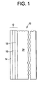
- Figure 1 illustrates a partial cross sectional view of the mold 10.
- the mold includes a facecoat structure 12 that includes an innermost layer 14, a sintered layer 16, and a delamination layer 18.
- the mold body 20 is formed on the delamination layer and typically includes multiple ceramic layers until a desired thickness is achieved.
- the innermost layer 12 is positioned to directly contact the casting metal when deposited into the mold cavity.
- the innermost facecoat layer 14 is generally made from ceramic materials that are relatively inert with the casting metal.
- the innermost layer is configured to remain in contact with the cast metal even as shrinkage occurs. This remnant facecoat material attached on the surface of the cast metal serves to physically separate the cast metal from attack by the liquid cooling media.
- the innermost layer can be formed from a slurry of materials that include a binder and a refractory metal or metal oxide such as, but not limited to, alumina, calcia, silica, zirconia, zircon, yttria, titania, yttria washed alumina, physical mixtures thereof, and chemical mixtures thereof (i.e., reaction products of these materials).
- the binder is often a silica-based material. Colloidal silica is very popular for this purpose, and is widely used for investment-casting molds. Commercially available colloidal silica grades of this type often have a silica content of approximately 10%-50%.
- the slurry for this layer as well as the other layers that form the mold can be formed by mixing the refractory metal/metal oxide and binder with a liquid such as water.
- the innermost facecoat slurry can be applied on the surface of the mold wax pattern by dip or spray coating. Additional innermost facecoat slurry can also be applied by "washing" the inside surfaces of a mold with the slurry after it has been made.
- the choice of the innermost facecoat material depends, to a large degree, on the metal being cast. As most metals are highly reactive, particularly at the elevated temperatures used during investment casting processes, it follows that the material used to produce the innermost layer is substantially non-reactive with the molten metal or alloy being cast under the conditions of the casting process. Yttria is a currently preferred facecoat material for casting articles from titanium and titanium alloys, primarily because it is less reactive with molten titanium and titanium alloys than most other mold-forming materials. On the other hand, some degree of reaction with the cast metal surface is desirable in order for the innermost facecoat material to be attached to the metal surfaces while the cast metal shrinks away from the rest of the mold after solidification.
- the selection of the innermost facecoat chemistry thus needs to consider generating an adequate degree of facecoat-metal reaction, which is not too severe to produce unacceptably reacted metal surfaces but sufficient for the facecoat material to be attached to the cast surfaces.
- yttria tends to react with nickel-base superalloys modestly and is a preferred ingredient for making the innermost facecoat for investment casting of superalloys.
- Another consideration for selecting the chemistry for the innermost facecoat slurry is to include a second oxide ingredient that can react with the first ingredient as discussed above.
- the intra-facecoat reaction is desirable to bond the particles within the innermost facecoat layer together, so that a whole layer of the innermost facecoat material can be attached to the cast metal surfaces, rather than just the individual facecoat particles in direct contact with the metal surfaces.
- alumina or silica particles or combination thereof are preferred candidates for this second ingredient for the innermost facecoat slurry.
- This second ingredient should be added in relatively small quantities sufficient to produce the desirable inter-particle bonding, but not enough to hinder the reaction between the cast metal and the first ingredient.
- the overall thickness of the innermost facecoat layer 14, which can be formed as a single layer or as multiple layers, is about 5 microns to about 500 microns, or more preferably, about 10 microns to about 150 microns.
- the innermost facecoat layer should have relatively fine particle sizes of about 1 micron to about 100 microns, or more preferably, from 2 microns to about 50 microns.
- the sintered layer 16 is continuous and dense with interparticle crevices filled by a sintering mechanism during the mold preheat and solidification process.
- the sintered layer serves to provide a tight barrier to ingress of liquid cooling agent and prevent direct contact with the cast metal.
- the sintered layer can be formed of a binder and a refractory metal and/or metal oxide similar to those described above.
- the composition can include ytrria, alumina and silica.
- the sintered layer is preferably fabricated from a slurry that has a different mix of the ingredients than that of the innermost facecoat layer 14.
- the sintered layer slurry should contain a higher concentration of the secondary ingredient than that of the innermost facecoat slurry.
- the higher secondary ingredient content will produce a higher degree of inter-particle reaction and thus a denser layer facecoat structure that can provide tight seal to any further ingress of the cooling media to attack the cast metal.
- the preferred secondary ingredient to increase in the sintered layer is silica, which is known to be able to react with yttria and alumina to form a low-melting product that can fill the interstices of the facecoat particles during the casting process.
- the function of the sintered layer 16 is similar to that of the innermost facecoat layer 14 in that they both provide physical barrier to protect the cast metal from being contacted and reacted by any ingress of the cooling metal media.
- a dense sintered facecoat layer structure With the formation of a dense sintered facecoat layer structure, it provides a more ensuring protection of the cast metal in addition to the generally more porous innermost facecoat layer.
- a sintered layer may not be necessary to achieve desirable protection of the cast metal. In this sense, a separate sintered facecoat layer is optional, not critical in the graded facecoat structure as taught in this invention.
- the overall thickness of the sintered layer which can be formed as a single layer or as multiple layers, is about 0 to about 200 microns, or more preferably, about 10 microns to 50 microns.
- the refractory materials have an average diameter of about 1 micron to about 100 microns, or more preferably, about 2 microns to about 50 microns.
- the delamination layer 18 is formed of a binder and refractory materials.
- the delamination layer is porous; the amount of which is effective to break away from the main body of the mold upon cooling (i.e., shrinkage) of the casting metal.
- the layer formed by stucco particles between slurry layers generally has a high concentration of porosity. Facecoat delamination can thus occur within or next to the facecoat stucco layer.
- a delamination layer can also be induced within the facecoat region if a more porous region can be produced.
- the binding element of the facecoat chemistry can be depleted inside of the facecoat layer. This complex interaction among metal, facecoat, and stucco can lead to the formation of a porous layer within the facecoat region.
- the reaction-induced porous layers within the facecoat region generally result from local depletion of silica during the facecoat reaction.
- the delamination layer 18 can form between the innermost facecoat layer 14 and the sintered layer 16, or outside of the sintered layer as shown in Figure 1 . Disregarding the specific location of the delamination layer 18, both the innermost layer 14 and the sintered layer 16, if formed according to the present teaching, are able to provide protection for the cast metal. In general, however, it is preferred that the delamination layer 18 is situated outside of the sintered layer 16, so that both the innermost facecoat layer 14 and the sintered facecoat layer 16 can be detached from the rest of the mold to part with the cast metal during shrinkage.
- the pores provide the layer with a porosity of 10 to 40 % in one embodiment, and 30 to 60 % in other embodiments.
- the particle sizes of the refractory materials are about 1 microns to about 100 microns in one example, and about 10 microns to about 150 microns in another example.
- An exemplary delamination layer composition includes zircon, silica, yttria and alumina particles.
- the overall thickness of the delamination layer which can be formed as a single layer or as multiple layers, is about 1 micron to about 100 microns in one example, and about 10 microns to 500 microns in other
- the mold body 20 can be formed of multiple layers and is not intended to be limited to any particular material or materials.
- the mold material is typically selected from a binder and a refractory material comprising quartz, fused silica, calcia, zircon, zirconia, alumina, aluminosilicate, and yttria washed alumina, tungsten, yttria, titania and combinations thereof.
- the process for forming the mold with the graded facecoat structure as described above includes dipping a wax pattern (patterns made from other polymers also can be used) into a slurry composition or spray coating that will define the particular layer composition so as to coat the pattern with a layer of slurry.
- the innermost layer for contacting the molten metal or alloy to be cast is first formed and then stuccoed while wet with relatively coarse ceramic particulates (stucco).
- the stucco layer can be applied using a fluidized bed by spray coating, or by rain coating. Suitable rain coating devices are commercially available form Pacific Kiln & Insulations Co., Inc.
- the sintered and delamination layers may then be sequentially formed by repeating the sequence of dipping the pattern in the desired slurry composition, draining excess slurry, and stuccoing the requisite number of times corresponding to the number of layers desired.
- each slurry/stucco layer is dried prior to carrying out the next coating and stuccoing operation.
- a slurry coating is allowed to dry without stuccoing prior to applying the next slurry coating. The elimination of certain stucco steps can be an effective way to create the desirable graded facecoat structure as taught by the present invention.
- the materials useful as stucco materials are substantially the same as those materials currently considered useful as mold-forming materials, i.e., alumina, calcia, silica, zirconia, zircon, yttria, physical mixtures thereof, and chemical mixtures thereof.
- a primary difference between mold-forming materials and stuccos is particle size, i.e., stuccos generally have larger particle sizes than other mold-forming materials such as the refractory metal/metal oxides that form the slurry.
- a range of particle sizes for facecoat stucco materials generally is from about 10 microns to about 200 microns.
- the backup layers that constitute the outer body of the mold generally include stuccos having a particle size of from about 20 microns to about 250 microns. Stuccos, as well as other mold refractory materials, can be formed as intimate mixtures with other stucco materials for practicing the present invention.
- additional layers such as from about 2 to about 25 additional layers, typically from about 5 to about 20 additional layers, and more typically from about 10 to about 15 additional layers, are applied to the pattern to form the mold body 20.
- additional layers such as from about 2 to about 25 additional layers, typically from about 5 to about 20 additional layers, and more typically from about 10 to about 15 additional layers, are applied to the pattern to form the mold body 20.
- the wax model is eliminated from the shell mold, and the mold is fired.
- the shell is filled with molten metal.
- the mold is cooled to room temperature, and is stored for later use. Subsequent re-heating of the mold will be controlled so as not to cause cracking.
- Various methods have been used to introduce molten metal into shells including gravity, pressure, vacuum and centrifugal methods. When the molten metal in the casting mold has solidified and cooled sufficiently, the casting may be removed from the shell.
- Fig. 2 depicts an exemplary embodiment of a furnace 50 that can be used to cast molten materials via directional solidification processes.
- the furnace 50 can include resistance heated conductive strips 52 (e.g., graphite strips) disposed within an insulated furnace box 54 for preheating the box 54.
- the conductive strips can be replaced by an induction coil in an alternative embodiment.
- a mold positioner 64 can hold a ceramic mold 56 having an inner surface coated with a metal oxide slurry within the furnace box 54.
- An interior of the mold 56 can be filled with a molten material that is kept in the molten state by heating the furnace box 54 at a temperature above the melting point of the molten material.
- Directional solidification can be achieved by lowering the mold 56 containing the molten material out of the heated furnace box 54 (i.e., the hot zone) into a liquid cooling bath 60 (i.e., the cold zone) through an aperture 58 in the furnace box 54.
- the cooling bath 60 can act as a cooling medium for the molten material.
- the cooling bath 60 can be contained in a crucible 62 of metal such as a refractory metal that is heated to a temperature below the melting point of the molten material and above the melting point of the liquid cooling medium.
- Solidification of the molten material can progress from bottom to top within mold 56 as the mold 56 is lowered into the cooling bath 60.
- a solid-liquid interface can advance upward as heat is transferred from the molten material within the mold 56 to the liquid cooling bath 60.
- a satisfactory liquid cooling agent for the cooling bath of a directional solidification furnace should have a melting point significantly below that of the casting metal alloy and a high thermal conductivity.
- the cooling agent should be chemically inert and have a low vapor pressure.
- Suitable metals include metals with melting points less than 700°C.
- Metals with melting points less than 700°C include, without limitation, lithium (186°C), sodium (98°C), magnesium (650°C), aluminum (660°C), potassium (63°C), zinc (419°C), gallium (30°C), selenium (220°C), rubidium (39°C), cadmium (320°C), indium (156°C), tin (232°C), antimony (630°C), tellurium (450°C), cesium (28°C), mercury (-39°C), thallium (300°C), lead (327°C), bismuth (276°C), and various combinations thereof.
- the graded ceramic facecoat can inhibit the liquid cooling medium from contacting the surface of the molten material within the mold.
- this infiltration of the liquid cooling medium can occur if the mold does not seal properly or if the mold cracks prematurely before the completion of the solidification process.
- the presence of the graded facecoat adjacent to the surface of the molten material can prevent or delay cross-diffusion between components of the liquid cooling medium and the molten material and any surface reactions between the two materials.
- the composition of the molten material desirably remains substantially the same and does not become contaminated during the solidification process.
- the furnace box 54 is preheated to a sufficiently high temperature to insure that alloy in shell mold 56 is melted. Mold 56 is then lowered by means of mold positioner 64 into the liquid metal coolant 60 at a prescribed rate. A solid-liquid interface advances upward as heat is conducted from the alloy within the shell mold 56 and is carried away by the cooling metal. A casted part with columnar and single crystal growth structure is fully formed after the alloy is sufficiently cooled by immersion into the cooling bath 60. The part can then be easily removed from the shell mold 56.
- Examples of materials that can be cast as described above include but are not limited to metals, metal alloys, superalloys, and combinations comprising at least one of the foregoing materials.
- the term "superalloy” refers to a nickel (Ni), cobalt (Co), or iron (Fe) based heat resistant alloy that has superior strength and oxidation resistance at high temperatures.
- Superalloys can also include a metal such as chromium (Cr) to impart surface stability and one or more minor constituent such as molybdenum (Mo), tungsten (W), niobium (Nb), titanium (Ti), and/or aluminum (Al) for strengthening purposes.
- Mo molybdenum
- W tungsten
- Nb niobium
- Ti titanium
- Al aluminum
- the terms “a” and “an” do not denote a limitation of quantity, but rather denote the presence of at least one of the referenced items. Moreover, the endpoints of all ranges directed to the same component or property are inclusive of the endpoint and independently combinable (e.g., “about 5 wt% to about 20 wt%,” is inclusive of the endpoints and all intermediate values of the ranges of "about 5 wt% to about 20 wt%,”).
- Reference throughout the specification to "one embodiment”, “another embodiment”, “an embodiment”, and so forth means that a particular element (e.g., feature, structure, and/or characteristic) described in connection with the embodiment is included in at least one embodiment described herein, and may or may not be present in other embodiments.
Landscapes
- Engineering & Computer Science (AREA)
- Mechanical Engineering (AREA)
- Chemical & Material Sciences (AREA)
- Crystallography & Structural Chemistry (AREA)
- Materials Engineering (AREA)
- Metallurgy (AREA)
- Organic Chemistry (AREA)
- Molds, Cores, And Manufacturing Methods Thereof (AREA)
- Turbine Rotor Nozzle Sealing (AREA)
Abstract
Description
- The present disclosure generally relates to casting molds for use in directional solidification casting processes and methods of making the same. More particularly, the casting mold includes a graded facecoat structure that is configured to prevent or delay a liquid metal cooling agent from reacting with a surface of the casting metal during the directional solidification process.
- Directional solidification processes are methods commonly employed for producing parts such as turbine blades and vanes with columnar and single crystal growth structures. It is well known that the high temperature mechanical properties of single crystal superalloys are superior to castings with polycrystalline structures. Generally, a desired single crystal growth structure is created at the base of a vertically disposed mold defining a part. Then, a single crystal solidification front is propagated through the structure under the influence of a moving thermal gradient.
- Various processes exist for directional solidification. In one process, directional solidification can be achieved by slowly lowering a mold containing molten metal out of a heated furnace and into a liquid cooling bath, which acts as a cooling medium for the molten material. The cooling bath can include a metal that is heated to a temperature below the melting point of the molten material and above the melting point of the liquid cooling agent. Solidification of the molten material can progress from the bottom to the top of the mold as the mold is lowered into the cooling bath. In this manner, a solid-liquid interface can advance upward as heat is transferred from the molten material within the mold to the liquid cooling bath. One of the problems of liquid cooling the mold is the propensity that the liquid cooling agent contaminates the casting material, resulting in undesirable surface pitting. Reaction of the liquid cooling agent with the casting metal can occur if the mold is not properly sealed or if it cracks prematurely before completion of a casting run.
- Facecoats are sometimes used to form a protective barrier between the molten casting metal and the surface of the shell mold. For example,
U.S. Pat. No. 6,676,381 (Subramanian et al. ) describes a facecoat based on yttria or at least one rare earth metal and other inorganic components, such as oxides, silicides, silicates, and sulfides. The facecoat compositions are most often in the form of slurries, which generally include a binder material along with a refractory material such as the yttria component. When a molten reactive casting metal is delivered into the shell mold, the facecoat prevents the undesirable reaction between the casting metal and the walls of the mold, i.e., the walls underneath the facecoat. Facecoats can sometimes be used, for the same purpose, to protect the portion of a core (within the shell mold), which would normally come into contact with the casting metal. Current facecoats are prone to failure such as when the mold body cracks during the casting process. - Accordingly, it would be desirable to have a casting mold suitable for directional solidification processes that employ a liquid cooling bath, wherein the mold is configured to prevent or delay a liquid metal cooling agent from reacting with a surface of the casting metal during the directional solidification process.
- Disclosed herein are molds for a directional solidification process and processes thereof. In one embodiment, the mold for a directional solidification process comprises a graded facecoat structure comprising an innermost layer for contacting molten metal during the directional solidification process and a delamination layer in contact with a mold body, wherein the delamination layer is configured to fracture upon directional solidification of the casting metal.
- In another embodiment, the mold comprises a graded facecoat structure comprising a innermost layer, a sintered layer, and a delamination layer comprising pores; and a mold body, wherein the innermost layer and the sintered layer are configured to adhere or remain in close proximity to the casting metal upon cooling and directional solidification of the casting metal, and wherein the mold body separates from the innermost layer and the sintered layer at about the delamination layer.
- A directional solidification casting process comprises casting a molten metal in a mold, wherein the mold comprises a graded facecoat structure formed on a mold body, the graded facecoat structure comprising an innermost layer for contacting the molten metal and a delamination layer; lowering the mold into a liquid cooling bath comprising a liquid cooling agent heated to a temperature below the melting point of the molten material and above the melting point of the liquid cooling agent; and transferring heat from the mold to the liquid cooling bath and directionally solidifying the molten metal as it is lowered into the liquid cooling bath; wherein the delamination layer fractures to separate the innermost layer from the mold body as the molten metal cools.
- The disclosure may be understood more readily by reference to the following detailed description of the various features of the disclosure and the examples included therein.
- Referring now to the figures wherein the like elements are numbered alike:
-
Figure 1 illustrates a partial sectional view of a casting mold in accordance with the present disclosure. -
Figure 2 depicts an exemplary embodiment of a furnace that can be used to cast molten materials via directional solidification processes - Disclosed herein are facecoat structures for a mold employed in a directional investment casting process. The facecoat structure generally includes a graded composition that includes an innermost layer that will contact the cast metal; a sintered layer adjacent to the innermost layer; and an outer delaminating layer near or next to the main body of the mold. The innermost and sintered layers are configured to break away from the mold at the delamination layer during the solidification process, wherein the innermost and sintered layers remain bonded to the cast metal surfaces as the metal solidifies and shrinks way from the mold body. As such, the detached layers, i.e., the innermost and sintered layers, will remain in close proximity to and/or in contact with the cast metal surfaces as it cools and protect them from direct contact and reaction with any liquid metal cooling agent that infiltrates into the mold during the direction solidification process.
-
Figure 1 illustrates a partial cross sectional view of themold 10. As shown and noted above, the mold includes afacecoat structure 12 that includes aninnermost layer 14, a sinteredlayer 16, and adelamination layer 18. The mold body 20 is formed on the delamination layer and typically includes multiple ceramic layers until a desired thickness is achieved. Theinnermost layer 12 is positioned to directly contact the casting metal when deposited into the mold cavity. - The
innermost facecoat layer 14 is generally made from ceramic materials that are relatively inert with the casting metal. In addition, as will be discussed in greater detail below, the innermost layer is configured to remain in contact with the cast metal even as shrinkage occurs. This remnant facecoat material attached on the surface of the cast metal serves to physically separate the cast metal from attack by the liquid cooling media. The innermost layer can be formed from a slurry of materials that include a binder and a refractory metal or metal oxide such as, but not limited to, alumina, calcia, silica, zirconia, zircon, yttria, titania, yttria washed alumina, physical mixtures thereof, and chemical mixtures thereof (i.e., reaction products of these materials). The binder is often a silica-based material. Colloidal silica is very popular for this purpose, and is widely used for investment-casting molds. Commercially available colloidal silica grades of this type often have a silica content of approximately 10%-50%. The slurry for this layer as well as the other layers that form the mold can be formed by mixing the refractory metal/metal oxide and binder with a liquid such as water. The innermost facecoat slurry can be applied on the surface of the mold wax pattern by dip or spray coating. Additional innermost facecoat slurry can also be applied by "washing" the inside surfaces of a mold with the slurry after it has been made. - The choice of the innermost facecoat material depends, to a large degree, on the metal being cast. As most metals are highly reactive, particularly at the elevated temperatures used during investment casting processes, it follows that the material used to produce the innermost layer is substantially non-reactive with the molten metal or alloy being cast under the conditions of the casting process. Yttria is a currently preferred facecoat material for casting articles from titanium and titanium alloys, primarily because it is less reactive with molten titanium and titanium alloys than most other mold-forming materials. On the other hand, some degree of reaction with the cast metal surface is desirable in order for the innermost facecoat material to be attached to the metal surfaces while the cast metal shrinks away from the rest of the mold after solidification. The selection of the innermost facecoat chemistry thus needs to consider generating an adequate degree of facecoat-metal reaction, which is not too severe to produce unacceptably reacted metal surfaces but sufficient for the facecoat material to be attached to the cast surfaces. In this regard, for example, yttria tends to react with nickel-base superalloys modestly and is a preferred ingredient for making the innermost facecoat for investment casting of superalloys.
- Another consideration for selecting the chemistry for the innermost facecoat slurry is to include a second oxide ingredient that can react with the first ingredient as discussed above. The intra-facecoat reaction is desirable to bond the particles within the innermost facecoat layer together, so that a whole layer of the innermost facecoat material can be attached to the cast metal surfaces, rather than just the individual facecoat particles in direct contact with the metal surfaces. In this regard, alumina or silica particles or combination thereof are preferred candidates for this second ingredient for the innermost facecoat slurry. This second ingredient should be added in relatively small quantities sufficient to produce the desirable inter-particle bonding, but not enough to hinder the reaction between the cast metal and the first ingredient.
- The overall thickness of the
innermost facecoat layer 14, which can be formed as a single layer or as multiple layers, is about 5 microns to about 500 microns, or more preferably, about 10 microns to about 150 microns. The innermost facecoat layer should have relatively fine particle sizes of about 1 micron to about 100 microns, or more preferably, from 2 microns to about 50 microns. - The sintered
layer 16 is continuous and dense with interparticle crevices filled by a sintering mechanism during the mold preheat and solidification process. The sintered layer serves to provide a tight barrier to ingress of liquid cooling agent and prevent direct contact with the cast metal. The sintered layer can be formed of a binder and a refractory metal and/or metal oxide similar to those described above. For example, the composition can include ytrria, alumina and silica. However, the sintered layer is preferably fabricated from a slurry that has a different mix of the ingredients than that of theinnermost facecoat layer 14. Generally, the sintered layer slurry should contain a higher concentration of the secondary ingredient than that of the innermost facecoat slurry. The higher secondary ingredient content will produce a higher degree of inter-particle reaction and thus a denser layer facecoat structure that can provide tight seal to any further ingress of the cooling media to attack the cast metal. The preferred secondary ingredient to increase in the sintered layer is silica, which is known to be able to react with yttria and alumina to form a low-melting product that can fill the interstices of the facecoat particles during the casting process. - It should be noted that the function of the
sintered layer 16 is similar to that of theinnermost facecoat layer 14 in that they both provide physical barrier to protect the cast metal from being contacted and reacted by any ingress of the cooling metal media. With the formation of a dense sintered facecoat layer structure, it provides a more ensuring protection of the cast metal in addition to the generally more porous innermost facecoat layer. In situations where the innermost facecoat layer is relatively thick, continuously uniform, and dense, a sintered layer may not be necessary to achieve desirable protection of the cast metal. In this sense, a separate sintered facecoat layer is optional, not critical in the graded facecoat structure as taught in this invention. - The overall thickness of the sintered layer, which can be formed as a single layer or as multiple layers, is about 0 to about 200 microns, or more preferably, about 10 microns to 50 microns. The refractory materials have an average diameter of about 1 micron to about 100 microns, or more preferably, about 2 microns to about 50 microns.
- The
delamination layer 18 is formed of a binder and refractory materials. In one embodiment, the delamination layer is porous; the amount of which is effective to break away from the main body of the mold upon cooling (i.e., shrinkage) of the casting metal. The layer formed by stucco particles between slurry layers generally has a high concentration of porosity. Facecoat delamination can thus occur within or next to the facecoat stucco layer. A delamination layer can also be induced within the facecoat region if a more porous region can be produced. Depending on the nature of the metal-facecoat reaction on the one side and the facecoat-stucco reaction on the other side, the binding element of the facecoat chemistry can be depleted inside of the facecoat layer. This complex interaction among metal, facecoat, and stucco can lead to the formation of a porous layer within the facecoat region. The reaction-induced porous layers within the facecoat region generally result from local depletion of silica during the facecoat reaction. - It is important to note that, depending on the formation mechanism, the
delamination layer 18 can form between theinnermost facecoat layer 14 and thesintered layer 16, or outside of the sintered layer as shown inFigure 1 . Disregarding the specific location of thedelamination layer 18, both theinnermost layer 14 and thesintered layer 16, if formed according to the present teaching, are able to provide protection for the cast metal. In general, however, it is preferred that thedelamination layer 18 is situated outside of thesintered layer 16, so that both theinnermost facecoat layer 14 and thesintered facecoat layer 16 can be detached from the rest of the mold to part with the cast metal during shrinkage. - The pores provide the layer with a porosity of 10 to 40 % in one embodiment, and 30 to 60 % in other embodiments. The particle sizes of the refractory materials are about 1 microns to about 100 microns in one example, and about 10 microns to about 150 microns in another example. An exemplary delamination layer composition includes zircon, silica, yttria and alumina particles. The overall thickness of the delamination layer, which can be formed as a single layer or as multiple layers, is about 1 micron to about 100 microns in one example, and about 10 microns to 500 microns in other
- The mold body 20 can be formed of multiple layers and is not intended to be limited to any particular material or materials. For directional solidification of superalloys, the mold material is typically selected from a binder and a refractory material comprising quartz, fused silica, calcia, zircon, zirconia, alumina, aluminosilicate, and yttria washed alumina, tungsten, yttria, titania and combinations thereof.
- Typically the process for forming the mold with the graded facecoat structure as described above includes dipping a wax pattern (patterns made from other polymers also can be used) into a slurry composition or spray coating that will define the particular layer composition so as to coat the pattern with a layer of slurry. The innermost layer for contacting the molten metal or alloy to be cast is first formed and then stuccoed while wet with relatively coarse ceramic particulates (stucco). The stucco layer can be applied using a fluidized bed by spray coating, or by rain coating. Suitable rain coating devices are commercially available form Pacific Kiln & Insulations Co., Inc. The sintered and delamination layers may then be sequentially formed by repeating the sequence of dipping the pattern in the desired slurry composition, draining excess slurry, and stuccoing the requisite number of times corresponding to the number of layers desired. In one embodiment, each slurry/stucco layer is dried prior to carrying out the next coating and stuccoing operation. In other embodiments, a slurry coating is allowed to dry without stuccoing prior to applying the next slurry coating. The elimination of certain stucco steps can be an effective way to create the desirable graded facecoat structure as taught by the present invention.
- The materials useful as stucco materials are substantially the same as those materials currently considered useful as mold-forming materials, i.e., alumina, calcia, silica, zirconia, zircon, yttria, physical mixtures thereof, and chemical mixtures thereof. A primary difference between mold-forming materials and stuccos is particle size, i.e., stuccos generally have larger particle sizes than other mold-forming materials such as the refractory metal/metal oxides that form the slurry. A range of particle sizes for facecoat stucco materials generally is from about 10 microns to about 200 microns. The backup layers that constitute the outer body of the mold generally include stuccos having a particle size of from about 20 microns to about 250 microns. Stuccos, as well as other mold refractory materials, can be formed as intimate mixtures with other stucco materials for practicing the present invention.
- Once the facecoat structure is solidified about the pattern, additional layers, such as from about 2 to about 25 additional layers, typically from about 5 to about 20 additional layers, and more typically from about 10 to about 15 additional layers, are applied to the pattern to form the mold body 20. After thorough drying, the wax model is eliminated from the shell mold, and the mold is fired. Sometimes, before the shell has cooled from this high temperature heating, the shell is filled with molten metal. Alternately, the mold is cooled to room temperature, and is stored for later use. Subsequent re-heating of the mold will be controlled so as not to cause cracking. Various methods have been used to introduce molten metal into shells including gravity, pressure, vacuum and centrifugal methods. When the molten metal in the casting mold has solidified and cooled sufficiently, the casting may be removed from the shell.
-
Fig. 2 depicts an exemplary embodiment of afurnace 50 that can be used to cast molten materials via directional solidification processes. As shown, thefurnace 50 can include resistance heated conductive strips 52 (e.g., graphite strips) disposed within aninsulated furnace box 54 for preheating thebox 54. The conductive strips can be replaced by an induction coil in an alternative embodiment. Amold positioner 64 can hold aceramic mold 56 having an inner surface coated with a metal oxide slurry within thefurnace box 54. An interior of themold 56 can be filled with a molten material that is kept in the molten state by heating thefurnace box 54 at a temperature above the melting point of the molten material. Directional solidification can be achieved by lowering themold 56 containing the molten material out of the heated furnace box 54 (i.e., the hot zone) into a liquid cooling bath 60 (i.e., the cold zone) through anaperture 58 in thefurnace box 54. The coolingbath 60 can act as a cooling medium for the molten material. The coolingbath 60 can be contained in acrucible 62 of metal such as a refractory metal that is heated to a temperature below the melting point of the molten material and above the melting point of the liquid cooling medium. Solidification of the molten material can progress from bottom to top withinmold 56 as themold 56 is lowered into the coolingbath 60. In particular, a solid-liquid interface can advance upward as heat is transferred from the molten material within themold 56 to theliquid cooling bath 60. - A satisfactory liquid cooling agent for the cooling bath of a directional solidification furnace should have a melting point significantly below that of the casting metal alloy and a high thermal conductivity. The cooling agent should be chemically inert and have a low vapor pressure. Suitable metals include metals with melting points less than 700°C. Metals with melting points less than 700°C include, without limitation, lithium (186°C), sodium (98°C), magnesium (650°C), aluminum (660°C), potassium (63°C), zinc (419°C), gallium (30°C), selenium (220°C), rubidium (39°C), cadmium (320°C), indium (156°C), tin (232°C), antimony (630°C), tellurium (450°C), cesium (28°C), mercury (-39°C), thallium (300°C), lead (327°C), bismuth (276°C), and various combinations thereof.
- If any of the liquid cooling agents, e.g., a liquid metal, infiltrates through the main mold body 20 during the solidification process, the graded ceramic facecoat can inhibit the liquid cooling medium from contacting the surface of the molten material within the mold. By way of example, this infiltration of the liquid cooling medium can occur if the mold does not seal properly or if the mold cracks prematurely before the completion of the solidification process. The presence of the graded facecoat adjacent to the surface of the molten material can prevent or delay cross-diffusion between components of the liquid cooling medium and the molten material and any surface reactions between the two materials. As a result, the composition of the molten material desirably remains substantially the same and does not become contaminated during the solidification process.
- In operation, the
furnace box 54 is preheated to a sufficiently high temperature to insure that alloy inshell mold 56 is melted.Mold 56 is then lowered by means ofmold positioner 64 into theliquid metal coolant 60 at a prescribed rate. A solid-liquid interface advances upward as heat is conducted from the alloy within theshell mold 56 and is carried away by the cooling metal. A casted part with columnar and single crystal growth structure is fully formed after the alloy is sufficiently cooled by immersion into the coolingbath 60. The part can then be easily removed from theshell mold 56. - Examples of materials that can be cast as described above include but are not limited to metals, metal alloys, superalloys, and combinations comprising at least one of the foregoing materials. As used herein, the term "superalloy" refers to a nickel (Ni), cobalt (Co), or iron (Fe) based heat resistant alloy that has superior strength and oxidation resistance at high temperatures. Superalloys can also include a metal such as chromium (Cr) to impart surface stability and one or more minor constituent such as molybdenum (Mo), tungsten (W), niobium (Nb), titanium (Ti), and/or aluminum (Al) for strengthening purposes. The physical properties of superalloys make them particularly useful for the manufacture of gas turbine components.
- As used herein, the terms "a" and "an" do not denote a limitation of quantity, but rather denote the presence of at least one of the referenced items. Moreover, the endpoints of all ranges directed to the same component or property are inclusive of the endpoint and independently combinable (e.g., "about 5 wt% to about 20 wt%," is inclusive of the endpoints and all intermediate values of the ranges of "about 5 wt% to about 20 wt%,"). Reference throughout the specification to "one embodiment", "another embodiment", "an embodiment", and so forth means that a particular element (e.g., feature, structure, and/or characteristic) described in connection with the embodiment is included in at least one embodiment described herein, and may or may not be present in other embodiments. In addition, it is to be understood that the described elements may be combined in any suitable manner in the various embodiments. It is also to be understood that the disclosure is not limited by any theories described therein. Unless defined otherwise, technical and scientific terms used herein have the same meaning as is commonly understood by one of skill in the art to which this invention belongs.
- This written description uses examples to disclose the invention, including the best mode, and also to enable any person skilled in the art to make and use the invention. The patentable scope of the invention is defined by the claims, and may include other examples that occur to those skilled in the art. Such other examples are intended to be within the scope of the claims if they have structural elements that do not differ from the literal language of the claims, or if they include equivalent structural elements with insubstantial differences from the literal languages of the claims.
- For completeness, various aspects of the invention are now set out in the following numbered clauses:
- 1. A mold for a directional solidification process, the mold comprising:
- a graded facecoat structure comprising an innermost layer for contacting molten metal during the directional solidification process and a delamination layer in contact with a mold body, wherein the delamination layer is configured to fracture upon directional solidification of the casting metal.
- 2. The mold of clause 1, further comprising a sintered layer intermediate to the innermost layer and the delaminating layer.
- 3. The mold of clause 1, wherein the delamination layer is at a thickness of 1 to 100 microns with a porosity of 10 to 40 percent.
- 4. The mold of clause 1, wherein the delamination layer is at a thickness of 10 to 500 microns with a porosity of 30 to 60 percent.
- 5. The mold of clause 2, wherein the innermost layer has a thickness of 5 to 500 microns, the delamination has a thickness of 1 to 500 microns, and the sintered layer has a thickness of 0 to 200 microns.
- 6. The mold of clause 1, wherein the innermost layer is configured to remain in contact with the molten metal as shrinkage occurs.
- 7. The mold of clause 1, wherein the innermost layer and delamination layers comprise a binder and refractory metal or metal oxides.
- 8. A mold for directional solidification of a casting metal, the mold comprising:
- a graded facecoat structure comprising a innermost layer, a sintered layer, and a delamination layer comprising pores; and
- a mold body, wherein the innermost layer and the sintered layer are configured to adhere or remain in close proximity to the casting metal upon cooling and directional solidification of the casting metal, and wherein the mold body separates from the innermost layer and the sintered layer at about the delamination layer.
- 9. The mold of clause 8, wherein the sintered layer comprises a refractory metal and/or metal oxide having an average particle size of 1 to 100 microns.
- 10. The mold of clause 8, wherein the delamination layer is at a thickness of 10 to 500 microns with a porosity of 30 to 60 percent.
- 11. The mold of clause 8, wherein the delamination layer is at a thickness of 1 to 100 microns with a porosity of 10 to 40 percent.
- 12. The mold of clause 8, wherein the innermost layer and delamination layers comprise a binder and refractory metal or metal oxides.
- 13. The mold of clause 8, wherein the casting metal comprises metals, metal alloys, superalloys, and combinations comprising at least one of the foregoing materials.
- 14. The mold of clause 8, wherein the sintering layer is configured to sinter during a mold preheat and solidification process.
- 15. A directional solidification casting process comprising:
- casting a molten metal in a mold, wherein the mold comprises a graded facecoat structure formed on a mold body, the graded facecoat structure comprising an innermost layer for contacting the molten metal and a delamination layer;
- lowering the mold into a liquid cooling bath comprising a liquid cooling agent heated to a temperature below the melting point of the molten material and above the melting point of the liquid cooling agent; and
- transferring heat from the mold to the liquid cooling bath and directionally solidifying the molten metal as it is lowered into the liquid cooling bath; wherein the delamination layer fractures to separate the innermost layer from the mold body as the molten metal cools.
- 16. The directional solidification process of clause 15, wherein the delamination layer is at a thickness of 1 to 100 microns with a porosity of 10 to 40 percent.
- 17. The directional solidification process of clause 15, further comprising forming a sintering layer intermediate the innermost layer and the delamination layer, wherein the sintering layer is sintered during the solidification process.
- 18. The directional solidification process of clause 15, wherein the innermost layer contacts the molten metal as the molten metal cools in the liquid cooling bath.
- 19. The directional solidification process of clause 15, wherein the liquid cooling agent comprises a metal having a melting point less than 700°C.
- 20. The directional solidification process of clause 15, wherein the molten metal comprises metals, metal alloys, superalloys, and combinations comprising at least one of the foregoing materials.
Claims (13)
- A mold (10) for a directional solidification process, the mold (10) comprising:a graded facecoat structure (12) comprising an innermost layer (14) for contacting molten metal during the directional solidification process and a delamination layer (18) in contact with a mold body (20), wherein the delamination layer (18) is configured to fracture upon directional solidification of the casting metal.
- The mold (10) of claim 1, further comprising a sintered layer (16) intermediate to the innermost layer (14) and the delamination layer (18).
- The mold (10) of claim 1 or claim 2, wherein the delamination layer (18) is at a thickness of 1 to 100 microns with a porosity of 10 to 40 percent.
- The mold (10) of any preceding claim, wherein the delamination layer (18) is at a thickness of 10 to 500 microns with a porosity of 30 to 60 percent.
- The mold (10) of any one of claims 2 to 4, wherein the innermost layer (14) has a thickness of 5 to 500 microns, the delamination layer (18) has a thickness of 1 to 500 microns, and the sintered layer (16) has a thickness of 0 to 200 microns.
- The mold (10) of any preceding claim, wherein the innermost layer (14) is configured to remain in contact with the molten metal as shrinkage occurs.
- The mold (10) of any preceding claim, wherein the innermost layer (14) and delamination layer (18) comprise a binder and refractory metal or metal oxides.
- A directional solidification casting process comprising:casting a molten metal in a mold (10, 56), wherein the mold comprises a graded facecoat structure (12) formed on a mold body (20), the graded facecoat structure (12) comprising an innermost layer (14) for contacting the molten metal and a delamination layer (18);lowering the mold (10, 56) into a liquid cooling bath (60) comprising a liquid cooling agent heated to a temperature below the melting point of the molten material and above the melting point of the liquid cooling agent; andtransferring heat from the mold (10, 56) to the liquid cooling bath (60) and directionally solidifying the molten metal as it is lowered into the liquid cooling bath (60); wherein the delamination layer (18) fractures to separate the innermost layer (14) from the mold body (20) as the molten metal cools.
- The directional solidification process of claim 8, wherein the delamination layer (18) is at a thickness of 1 to 100 microns with a porosity of 10 to 40 percent.
- The directional solidification process of claim 8 or claim 9, further comprising forming a sintering layer (16) intermediate the innermost layer (14) and the delamination layer (18), wherein the sintering layer (16) is sintered during the solidification process.
- The directional solidification process of any one of claims 8 to 10, wherein the innermost layer contacts the molten metal as the molten metal cools in the liquid cooling bath.
- The directional solidification process of any one of claims 8 to 11, wherein the liquid cooling agent comprises a metal having a melting point less than 700°C.
- The directional solidification process of any one of claims 8 to 12, wherein the molten metal comprises metals, metal alloys, superalloys, and combinations comprising at least one of the foregoing materials.
Priority Applications (1)
| Application Number | Priority Date | Filing Date | Title |
|---|---|---|---|
| PL09180169T PL2208556T3 (en) | 2009-01-06 | 2009-12-21 | Casting molds for use in directional solidification processes and methods of making |
Applications Claiming Priority (1)
| Application Number | Priority Date | Filing Date | Title |
|---|---|---|---|
| US12/348,937 US8307881B2 (en) | 2009-01-06 | 2009-01-06 | Casting molds for use in directional solidification processes and methods of making |
Publications (2)
| Publication Number | Publication Date |
|---|---|
| EP2208556A1 true EP2208556A1 (en) | 2010-07-21 |
| EP2208556B1 EP2208556B1 (en) | 2018-02-21 |
Family
ID=42072802
Family Applications (1)
| Application Number | Title | Priority Date | Filing Date |
|---|---|---|---|
| EP09180169.6A Not-in-force EP2208556B1 (en) | 2009-01-06 | 2009-12-21 | Casting molds for use in directional solidification processes and methods of making |
Country Status (5)
| Country | Link |
|---|---|
| US (1) | US8307881B2 (en) |
| EP (1) | EP2208556B1 (en) |
| JP (1) | JP5437788B2 (en) |
| CN (1) | CN101885037B (en) |
| PL (1) | PL2208556T3 (en) |
Cited By (1)
| Publication number | Priority date | Publication date | Assignee | Title |
|---|---|---|---|---|
| WO2014004496A1 (en) * | 2012-06-25 | 2014-01-03 | Silicor Materials Inc. | Lining for surfaces of a refractory crucible for purification of silicon and method of purification of the silicon melt using that crucible (s) for melting and further directional solidification |
Families Citing this family (5)
| Publication number | Priority date | Publication date | Assignee | Title |
|---|---|---|---|---|
| US8752611B2 (en) | 2011-08-04 | 2014-06-17 | General Electric Company | System and method for directional casting |
| US9592548B2 (en) * | 2013-01-29 | 2017-03-14 | General Electric Company | Calcium hexaluminate-containing mold and facecoat compositions and methods for casting titanium and titanium aluminide alloys |
| CN106141106A (en) * | 2015-03-31 | 2016-11-23 | 株式会社日立制作所 | The coating method of the coating of metal casting mould and this metal casting mould |
| CN105033180B (en) * | 2015-06-26 | 2017-03-01 | 北京北冶功能材料有限公司 | Improve the precision-investment casting method that directional solidification castings solidify radiating condition |
| CN113369465B (en) * | 2021-06-24 | 2022-08-23 | 郑州轻工业大学 | A kind of multi-gradient yttrium oxide type shell and preparation method thereof |
Citations (4)
| Publication number | Priority date | Publication date | Assignee | Title |
|---|---|---|---|---|
| US4664172A (en) * | 1984-08-09 | 1987-05-12 | Agency Of Industrial Science And Technology | Method for production of investment shell mold for grain-oriented casting of super alloy |
| US6676381B2 (en) | 2002-04-03 | 2004-01-13 | General Electric Company | Method and apparatus for casting near-net shape articles |
| EP1595620A1 (en) * | 2004-05-12 | 2005-11-16 | Snecma | Broken mould moulding method |
| US20060130996A1 (en) * | 2004-12-22 | 2006-06-22 | General Electric Company | Shell mold for casting niobium-silicide alloys, and related compositions and processes |
Family Cites Families (14)
| Publication number | Priority date | Publication date | Assignee | Title |
|---|---|---|---|---|
| JPH0628773B2 (en) * | 1985-04-22 | 1994-04-20 | 旭有機材工業株式会社 | Mold material |
| US4966225A (en) * | 1988-06-13 | 1990-10-30 | Howmet Corporation | Ceramic shell mold for investment casting and method of making the same |
| US5275227A (en) | 1990-09-21 | 1994-01-04 | Sulzer Brothers Limited | Casting process for the production of castings by directional or monocrystalline solidification |
| JPH05208241A (en) * | 1992-01-31 | 1993-08-20 | Hitachi Metals Ltd | Casting mold for precision casting of titanium or titanium alloy |
| CN1061704C (en) * | 1995-11-14 | 2001-02-07 | 中国科学院金属研究所 | Technique for preparing monocrystal of metal material |
| JPH11104784A (en) * | 1997-10-06 | 1999-04-20 | Yasugi Seisakusho:Kk | Precision forging mold and manufacture |
| US6217286B1 (en) * | 1998-06-26 | 2001-04-17 | General Electric Company | Unidirectionally solidified cast article and method of making |
| JP3269474B2 (en) * | 1999-01-12 | 2002-03-25 | 三菱マテリアル株式会社 | High-strength precision casting mold and method of manufacturing the same |
| US6276433B1 (en) * | 1999-10-25 | 2001-08-21 | General Electric Company | Liquid metal cooled directional solidification process |
| US6308767B1 (en) * | 1999-12-21 | 2001-10-30 | General Electric Company | Liquid metal bath furnace and casting method |
| JP3592252B2 (en) * | 2001-04-05 | 2004-11-24 | 日信工業株式会社 | Casting method and casting apparatus |
| US6702886B2 (en) * | 2001-11-20 | 2004-03-09 | Alcoa Inc. | Mold coating |
| CN2629875Y (en) * | 2003-03-10 | 2004-08-04 | 中国科学院金属研究所 | silicon carbide section mould for directional solidification |
| JP4749193B2 (en) * | 2005-03-30 | 2011-08-17 | 旭有機材工業株式会社 | Mold material for shell mold |
-
2009
- 2009-01-06 US US12/348,937 patent/US8307881B2/en not_active Expired - Fee Related
- 2009-12-21 PL PL09180169T patent/PL2208556T3/en unknown
- 2009-12-21 EP EP09180169.6A patent/EP2208556B1/en not_active Not-in-force
- 2009-12-28 JP JP2009296937A patent/JP5437788B2/en not_active Expired - Fee Related
-
2010
- 2010-01-06 CN CN201010003820.8A patent/CN101885037B/en not_active Expired - Fee Related
Patent Citations (4)
| Publication number | Priority date | Publication date | Assignee | Title |
|---|---|---|---|---|
| US4664172A (en) * | 1984-08-09 | 1987-05-12 | Agency Of Industrial Science And Technology | Method for production of investment shell mold for grain-oriented casting of super alloy |
| US6676381B2 (en) | 2002-04-03 | 2004-01-13 | General Electric Company | Method and apparatus for casting near-net shape articles |
| EP1595620A1 (en) * | 2004-05-12 | 2005-11-16 | Snecma | Broken mould moulding method |
| US20060130996A1 (en) * | 2004-12-22 | 2006-06-22 | General Electric Company | Shell mold for casting niobium-silicide alloys, and related compositions and processes |
Cited By (1)
| Publication number | Priority date | Publication date | Assignee | Title |
|---|---|---|---|---|
| WO2014004496A1 (en) * | 2012-06-25 | 2014-01-03 | Silicor Materials Inc. | Lining for surfaces of a refractory crucible for purification of silicon and method of purification of the silicon melt using that crucible (s) for melting and further directional solidification |
Also Published As
| Publication number | Publication date |
|---|---|
| EP2208556B1 (en) | 2018-02-21 |
| CN101885037B (en) | 2015-04-01 |
| PL2208556T3 (en) | 2018-08-31 |
| JP5437788B2 (en) | 2014-03-12 |
| JP2010158720A (en) | 2010-07-22 |
| US8307881B2 (en) | 2012-11-13 |
| CN101885037A (en) | 2010-11-17 |
| US20100170654A1 (en) | 2010-07-08 |
Similar Documents
| Publication | Publication Date | Title |
|---|---|---|
| RU2529134C2 (en) | Alloy casts with protective plies and method of their production | |
| EP2153919B1 (en) | High emittance shell molds for directional casting | |
| EP2208556B1 (en) | Casting molds for use in directional solidification processes and methods of making | |
| TWI439653B (en) | Reinforced refractory crucibles for melting titanium alloys | |
| TWI460387B (en) | Refractory crucibles capable of managing thermal stress and suitable for melting highly reactive alloys | |
| US8210240B2 (en) | Casting processes, casting apparatuses therefor, and castings produced thereby | |
| CN106363131B (en) | The method that Ti alloy casting is modified with ceramic shell surface layer | |
| EP2650062A2 (en) | Composite core for casting processes, and processes of making and using same | |
| US7296616B2 (en) | Shell mold for casting niobium-silicide alloys, and related compositions and processes | |
| CN106734852A (en) | A kind of anti-sticking tin liquid metal cools down the preparation method of directional solidification ceramic shell | |
| CN106311980B (en) | A kind of preparation method of high temperature alloy orientation/single crystal blade casting ceramic shell | |
| US5335717A (en) | Oxidation resistant superalloy castings | |
| CN103192062A (en) | Mold case for producing high-temperature alloy single crystal blades | |
| JP5925411B2 (en) | Casting process and yttria-containing facecoat material therefor | |
| US20030213575A1 (en) | Melting crucible and method | |
| US20090205799A1 (en) | Casting molds for use in a directional solidification process and methods of making | |
| CN113373502A (en) | Process method for controlling freckle defect in single crystal casting | |
| CN101839642B (en) | Fire-clay crucible capable of reacting thermal stress and being suitable for melting alloy with high activity | |
| JP2014226668A (en) | Precision-casting molding material, precision-casting mold and method for manufacturing the same | |
| JPS6366894B2 (en) |
Legal Events
| Date | Code | Title | Description |
|---|---|---|---|
| PUAI | Public reference made under article 153(3) epc to a published international application that has entered the european phase |
Free format text: ORIGINAL CODE: 0009012 |
|
| AK | Designated contracting states |
Kind code of ref document: A1 Designated state(s): AT BE BG CH CY CZ DE DK EE ES FI FR GB GR HR HU IE IS IT LI LT LU LV MC MK MT NL NO PL PT RO SE SI SK SM TR |
|
| AX | Request for extension of the european patent |
Extension state: AL BA RS |
|
| 17P | Request for examination filed |
Effective date: 20110121 |
|
| 17Q | First examination report despatched |
Effective date: 20130131 |
|
| GRAP | Despatch of communication of intention to grant a patent |
Free format text: ORIGINAL CODE: EPIDOSNIGR1 |
|
| INTG | Intention to grant announced |
Effective date: 20170719 |
|
| GRAS | Grant fee paid |
Free format text: ORIGINAL CODE: EPIDOSNIGR3 |
|
| GRAA | (expected) grant |
Free format text: ORIGINAL CODE: 0009210 |
|
| AK | Designated contracting states |
Kind code of ref document: B1 Designated state(s): AT BE BG CH CY CZ DE DK EE ES FI FR GB GR HR HU IE IS IT LI LT LU LV MC MK MT NL NO PL PT RO SE SI SK SM TR |
|
| REG | Reference to a national code |
Ref country code: GB Ref legal event code: FG4D |
|
| REG | Reference to a national code |
Ref country code: CH Ref legal event code: EP |
|
| REG | Reference to a national code |
Ref country code: DE Ref legal event code: R096 Ref document number: 602009050824 Country of ref document: DE Ref country code: AT Ref legal event code: REF Ref document number: 971154 Country of ref document: AT Kind code of ref document: T Effective date: 20180315 |
|
| REG | Reference to a national code |
Ref country code: IE Ref legal event code: FG4D |
|
| REG | Reference to a national code |
Ref country code: NL Ref legal event code: MP Effective date: 20180221 |
|
| REG | Reference to a national code |
Ref country code: LT Ref legal event code: MG4D |
|
| REG | Reference to a national code |
Ref country code: AT Ref legal event code: MK05 Ref document number: 971154 Country of ref document: AT Kind code of ref document: T Effective date: 20180221 |
|
| PG25 | Lapsed in a contracting state [announced via postgrant information from national office to epo] |
Ref country code: CY Free format text: LAPSE BECAUSE OF FAILURE TO SUBMIT A TRANSLATION OF THE DESCRIPTION OR TO PAY THE FEE WITHIN THE PRESCRIBED TIME-LIMIT Effective date: 20180221 Ref country code: LT Free format text: LAPSE BECAUSE OF FAILURE TO SUBMIT A TRANSLATION OF THE DESCRIPTION OR TO PAY THE FEE WITHIN THE PRESCRIBED TIME-LIMIT Effective date: 20180221 Ref country code: FI Free format text: LAPSE BECAUSE OF FAILURE TO SUBMIT A TRANSLATION OF THE DESCRIPTION OR TO PAY THE FEE WITHIN THE PRESCRIBED TIME-LIMIT Effective date: 20180221 Ref country code: NO Free format text: LAPSE BECAUSE OF FAILURE TO SUBMIT A TRANSLATION OF THE DESCRIPTION OR TO PAY THE FEE WITHIN THE PRESCRIBED TIME-LIMIT Effective date: 20180521 Ref country code: NL Free format text: LAPSE BECAUSE OF FAILURE TO SUBMIT A TRANSLATION OF THE DESCRIPTION OR TO PAY THE FEE WITHIN THE PRESCRIBED TIME-LIMIT Effective date: 20180221 Ref country code: HR Free format text: LAPSE BECAUSE OF FAILURE TO SUBMIT A TRANSLATION OF THE DESCRIPTION OR TO PAY THE FEE WITHIN THE PRESCRIBED TIME-LIMIT Effective date: 20180221 Ref country code: ES Free format text: LAPSE BECAUSE OF FAILURE TO SUBMIT A TRANSLATION OF THE DESCRIPTION OR TO PAY THE FEE WITHIN THE PRESCRIBED TIME-LIMIT Effective date: 20180221 |
|
| PG25 | Lapsed in a contracting state [announced via postgrant information from national office to epo] |
Ref country code: LV Free format text: LAPSE BECAUSE OF FAILURE TO SUBMIT A TRANSLATION OF THE DESCRIPTION OR TO PAY THE FEE WITHIN THE PRESCRIBED TIME-LIMIT Effective date: 20180221 Ref country code: SE Free format text: LAPSE BECAUSE OF FAILURE TO SUBMIT A TRANSLATION OF THE DESCRIPTION OR TO PAY THE FEE WITHIN THE PRESCRIBED TIME-LIMIT Effective date: 20180221 Ref country code: GR Free format text: LAPSE BECAUSE OF FAILURE TO SUBMIT A TRANSLATION OF THE DESCRIPTION OR TO PAY THE FEE WITHIN THE PRESCRIBED TIME-LIMIT Effective date: 20180522 Ref country code: BG Free format text: LAPSE BECAUSE OF FAILURE TO SUBMIT A TRANSLATION OF THE DESCRIPTION OR TO PAY THE FEE WITHIN THE PRESCRIBED TIME-LIMIT Effective date: 20180521 Ref country code: AT Free format text: LAPSE BECAUSE OF FAILURE TO SUBMIT A TRANSLATION OF THE DESCRIPTION OR TO PAY THE FEE WITHIN THE PRESCRIBED TIME-LIMIT Effective date: 20180221 |
|
| PG25 | Lapsed in a contracting state [announced via postgrant information from national office to epo] |
Ref country code: EE Free format text: LAPSE BECAUSE OF FAILURE TO SUBMIT A TRANSLATION OF THE DESCRIPTION OR TO PAY THE FEE WITHIN THE PRESCRIBED TIME-LIMIT Effective date: 20180221 Ref country code: RO Free format text: LAPSE BECAUSE OF FAILURE TO SUBMIT A TRANSLATION OF THE DESCRIPTION OR TO PAY THE FEE WITHIN THE PRESCRIBED TIME-LIMIT Effective date: 20180221 |
|
| REG | Reference to a national code |
Ref country code: DE Ref legal event code: R097 Ref document number: 602009050824 Country of ref document: DE |
|
| PG25 | Lapsed in a contracting state [announced via postgrant information from national office to epo] |
Ref country code: SK Free format text: LAPSE BECAUSE OF FAILURE TO SUBMIT A TRANSLATION OF THE DESCRIPTION OR TO PAY THE FEE WITHIN THE PRESCRIBED TIME-LIMIT Effective date: 20180221 Ref country code: CZ Free format text: LAPSE BECAUSE OF FAILURE TO SUBMIT A TRANSLATION OF THE DESCRIPTION OR TO PAY THE FEE WITHIN THE PRESCRIBED TIME-LIMIT Effective date: 20180221 Ref country code: DK Free format text: LAPSE BECAUSE OF FAILURE TO SUBMIT A TRANSLATION OF THE DESCRIPTION OR TO PAY THE FEE WITHIN THE PRESCRIBED TIME-LIMIT Effective date: 20180221 Ref country code: SM Free format text: LAPSE BECAUSE OF FAILURE TO SUBMIT A TRANSLATION OF THE DESCRIPTION OR TO PAY THE FEE WITHIN THE PRESCRIBED TIME-LIMIT Effective date: 20180221 |
|
| PLBE | No opposition filed within time limit |
Free format text: ORIGINAL CODE: 0009261 |
|
| STAA | Information on the status of an ep patent application or granted ep patent |
Free format text: STATUS: NO OPPOSITION FILED WITHIN TIME LIMIT |
|
| 26N | No opposition filed |
Effective date: 20181122 |
|
| PGFP | Annual fee paid to national office [announced via postgrant information from national office to epo] |
Ref country code: DE Payment date: 20181126 Year of fee payment: 10 Ref country code: PL Payment date: 20181123 Year of fee payment: 10 |
|
| PG25 | Lapsed in a contracting state [announced via postgrant information from national office to epo] |
Ref country code: SI Free format text: LAPSE BECAUSE OF FAILURE TO SUBMIT A TRANSLATION OF THE DESCRIPTION OR TO PAY THE FEE WITHIN THE PRESCRIBED TIME-LIMIT Effective date: 20180221 |
|
| PGFP | Annual fee paid to national office [announced via postgrant information from national office to epo] |
Ref country code: FR Payment date: 20181127 Year of fee payment: 10 Ref country code: IT Payment date: 20181122 Year of fee payment: 10 |
|
| REG | Reference to a national code |
Ref country code: CH Ref legal event code: PL |
|
| GBPC | Gb: european patent ceased through non-payment of renewal fee |
Effective date: 20181221 |
|
| PG25 | Lapsed in a contracting state [announced via postgrant information from national office to epo] |
Ref country code: LU Free format text: LAPSE BECAUSE OF NON-PAYMENT OF DUE FEES Effective date: 20181221 Ref country code: MC Free format text: LAPSE BECAUSE OF FAILURE TO SUBMIT A TRANSLATION OF THE DESCRIPTION OR TO PAY THE FEE WITHIN THE PRESCRIBED TIME-LIMIT Effective date: 20180221 |
|
| REG | Reference to a national code |
Ref country code: IE Ref legal event code: MM4A |
|
| REG | Reference to a national code |
Ref country code: BE Ref legal event code: MM Effective date: 20181231 |
|
| PG25 | Lapsed in a contracting state [announced via postgrant information from national office to epo] |
Ref country code: IE Free format text: LAPSE BECAUSE OF NON-PAYMENT OF DUE FEES Effective date: 20181221 |
|
| PG25 | Lapsed in a contracting state [announced via postgrant information from national office to epo] |
Ref country code: BE Free format text: LAPSE BECAUSE OF NON-PAYMENT OF DUE FEES Effective date: 20181231 |
|
| PG25 | Lapsed in a contracting state [announced via postgrant information from national office to epo] |
Ref country code: CH Free format text: LAPSE BECAUSE OF NON-PAYMENT OF DUE FEES Effective date: 20181231 Ref country code: GB Free format text: LAPSE BECAUSE OF NON-PAYMENT OF DUE FEES Effective date: 20181221 Ref country code: LI Free format text: LAPSE BECAUSE OF NON-PAYMENT OF DUE FEES Effective date: 20181231 |
|
| PG25 | Lapsed in a contracting state [announced via postgrant information from national office to epo] |
Ref country code: MT Free format text: LAPSE BECAUSE OF NON-PAYMENT OF DUE FEES Effective date: 20181221 |
|
| PG25 | Lapsed in a contracting state [announced via postgrant information from national office to epo] |
Ref country code: TR Free format text: LAPSE BECAUSE OF FAILURE TO SUBMIT A TRANSLATION OF THE DESCRIPTION OR TO PAY THE FEE WITHIN THE PRESCRIBED TIME-LIMIT Effective date: 20180221 |
|
| PG25 | Lapsed in a contracting state [announced via postgrant information from national office to epo] |
Ref country code: PT Free format text: LAPSE BECAUSE OF FAILURE TO SUBMIT A TRANSLATION OF THE DESCRIPTION OR TO PAY THE FEE WITHIN THE PRESCRIBED TIME-LIMIT Effective date: 20180221 |
|
| PG25 | Lapsed in a contracting state [announced via postgrant information from national office to epo] |
Ref country code: MK Free format text: LAPSE BECAUSE OF NON-PAYMENT OF DUE FEES Effective date: 20180221 Ref country code: HU Free format text: LAPSE BECAUSE OF FAILURE TO SUBMIT A TRANSLATION OF THE DESCRIPTION OR TO PAY THE FEE WITHIN THE PRESCRIBED TIME-LIMIT; INVALID AB INITIO Effective date: 20091221 |
|
| REG | Reference to a national code |
Ref country code: DE Ref legal event code: R119 Ref document number: 602009050824 Country of ref document: DE |
|
| PG25 | Lapsed in a contracting state [announced via postgrant information from national office to epo] |
Ref country code: IS Free format text: LAPSE BECAUSE OF FAILURE TO SUBMIT A TRANSLATION OF THE DESCRIPTION OR TO PAY THE FEE WITHIN THE PRESCRIBED TIME-LIMIT Effective date: 20180621 |
|
| PG25 | Lapsed in a contracting state [announced via postgrant information from national office to epo] |
Ref country code: DE Free format text: LAPSE BECAUSE OF NON-PAYMENT OF DUE FEES Effective date: 20200701 Ref country code: IT Free format text: LAPSE BECAUSE OF NON-PAYMENT OF DUE FEES Effective date: 20191221 Ref country code: FR Free format text: LAPSE BECAUSE OF NON-PAYMENT OF DUE FEES Effective date: 20191231 |
|
| PG25 | Lapsed in a contracting state [announced via postgrant information from national office to epo] |
Ref country code: PL Free format text: LAPSE BECAUSE OF NON-PAYMENT OF DUE FEES Effective date: 20191221 |