EP2207967B1 - Side channel compressor - Google Patents
Side channel compressor Download PDFInfo
- Publication number
- EP2207967B1 EP2207967B1 EP08847294A EP08847294A EP2207967B1 EP 2207967 B1 EP2207967 B1 EP 2207967B1 EP 08847294 A EP08847294 A EP 08847294A EP 08847294 A EP08847294 A EP 08847294A EP 2207967 B1 EP2207967 B1 EP 2207967B1
- Authority
- EP
- European Patent Office
- Prior art keywords
- side channel
- impeller
- gas
- flow
- impeller blades
- Prior art date
- Legal status (The legal status is an assumption and is not a legal conclusion. Google has not performed a legal analysis and makes no representation as to the accuracy of the status listed.)
- Not-in-force
Links
Images


Classifications
-
- F—MECHANICAL ENGINEERING; LIGHTING; HEATING; WEAPONS; BLASTING
- F04—POSITIVE - DISPLACEMENT MACHINES FOR LIQUIDS; PUMPS FOR LIQUIDS OR ELASTIC FLUIDS
- F04D—NON-POSITIVE-DISPLACEMENT PUMPS
- F04D23/00—Other rotary non-positive-displacement pumps
- F04D23/008—Regenerative pumps
-
- F—MECHANICAL ENGINEERING; LIGHTING; HEATING; WEAPONS; BLASTING
- F04—POSITIVE - DISPLACEMENT MACHINES FOR LIQUIDS; PUMPS FOR LIQUIDS OR ELASTIC FLUIDS
- F04D—NON-POSITIVE-DISPLACEMENT PUMPS
- F04D29/00—Details, component parts, or accessories
- F04D29/26—Rotors specially for elastic fluids
- F04D29/28—Rotors specially for elastic fluids for centrifugal or helico-centrifugal pumps for radial-flow or helico-centrifugal pumps
- F04D29/284—Rotors specially for elastic fluids for centrifugal or helico-centrifugal pumps for radial-flow or helico-centrifugal pumps for compressors
-
- F—MECHANICAL ENGINEERING; LIGHTING; HEATING; WEAPONS; BLASTING
- F04—POSITIVE - DISPLACEMENT MACHINES FOR LIQUIDS; PUMPS FOR LIQUIDS OR ELASTIC FLUIDS
- F04D—NON-POSITIVE-DISPLACEMENT PUMPS
- F04D29/00—Details, component parts, or accessories
- F04D29/66—Combating cavitation, whirls, noise, vibration or the like; Balancing
- F04D29/661—Combating cavitation, whirls, noise, vibration or the like; Balancing especially adapted for elastic fluid pumps
- F04D29/666—Combating cavitation, whirls, noise, vibration or the like; Balancing especially adapted for elastic fluid pumps by means of rotor construction or layout, e.g. unequal distribution of blades or vanes
-
- F—MECHANICAL ENGINEERING; LIGHTING; HEATING; WEAPONS; BLASTING
- F05—INDEXING SCHEMES RELATING TO ENGINES OR PUMPS IN VARIOUS SUBCLASSES OF CLASSES F01-F04
- F05D—INDEXING SCHEME FOR ASPECTS RELATING TO NON-POSITIVE-DISPLACEMENT MACHINES OR ENGINES, GAS-TURBINES OR JET-PROPULSION PLANTS
- F05D2240/00—Components
- F05D2240/20—Rotors
- F05D2240/30—Characteristics of rotor blades, i.e. of any element transforming dynamic fluid energy to or from rotational energy and being attached to a rotor
- F05D2240/307—Characteristics of rotor blades, i.e. of any element transforming dynamic fluid energy to or from rotational energy and being attached to a rotor related to the tip of a rotor blade
-
- F—MECHANICAL ENGINEERING; LIGHTING; HEATING; WEAPONS; BLASTING
- F05—INDEXING SCHEMES RELATING TO ENGINES OR PUMPS IN VARIOUS SUBCLASSES OF CLASSES F01-F04
- F05D—INDEXING SCHEME FOR ASPECTS RELATING TO NON-POSITIVE-DISPLACEMENT MACHINES OR ENGINES, GAS-TURBINES OR JET-PROPULSION PLANTS
- F05D2250/00—Geometry
- F05D2250/10—Two-dimensional
- F05D2250/18—Two-dimensional patterned
- F05D2250/182—Two-dimensional patterned crenellated, notched
Definitions
- the invention concerns a side channel compressor for compressing a gas.
- the invention therefore concerns a work machine for compressing gases, such as air or technical gases.
- the operation of the side channel compressor results in a broadband sound spectrum.
- tonal sound components occur at certain frequencies of the side channel compressor which are extremely annoying if they differ from the broadband sound spectrum by more than 7 dB.
- the essence of the invention is that at least one flow recess is provided in the free edge region of at least one impeller blade of the side channel compressor.
- the free edge region is the region which is located in the side channel and which may be surrounded by the gas to be compressed.
- the at least one flow recess or the amount of gas flowing through this flow recess, respectively reduces gas turbulence structures and/or periodic gas flow structures occurring at the trailing side of the impeller blades. This ensures a particularly silent operation of the side channel compressor.
- a side channel compressor shown in Figs. 1 to 3 for compressing a gas comprises an impeller 2 which is provided with impeller blades 1 and is mounted in a housing 3 for rotation about a horizontal central longitudinal axis 4.
- a conventional drive 6 serves for rotary drive of the impeller 2 in the direction of the arrow 5. The gas is thus transported through the housing 3 in the direction of the arrow 5 as well.
- the housing 3 comprises a housing body 7 and a demountable housing cover 8 which are joined together according to Figs. 1 and 2 so as to enclose the impeller 2 comprising the impeller blades 1 which is drivable for rotation and is disposed on a drive shaft 9 for co-rotation therewith.
- the impeller 2 is provided with a single blade ring and is designed like a disk.
- the impeller 2 comprises an inner impeller hub 10 with a central circular hub bore 11.
- the impeller hub 10 is formed by an inner hub foot 12 which radially outwardly delimits the hub bore 11, and by a radial circular hub washer 13 adjoining the hub foot 12.
- the impeller 2 comprises a radial outer carrier ring 14 which adjoins the outside of the hub washer 13 and overlaps with both sides of said hub washer 13 in the direction of the central longitudinal axis 4.
- the carrier ring 14 carries a multitude of radially projecting impeller blades 1 which are distributed in the circumferential direction.
- a total of 52 individual impeller blades 1 are provided which are preferably arranged equidistantly so as to have an angular distance from one another, relative to the central longitudinal axis 4, that amounts to approximately 7°.
- 6 to 7 impeller blades 1 are disposed at every 45°.
- the hub foot 12, the hub washer 13 and the carrier ring 14 form an integral cast part.
- axial and radial used in-here are relative to the central longitudinal axis 4.
- inner and outer are relative to the central longitudinal axis 4 as well.
- inner means that an inner region is nearer to the central longitudinal axis 4 than an outer region.
- the central hub bore 11 may receive the drive shaft 9.
- a conventional parallel-key connection is provided between the drive shaft 9 and the hub foot 12 so as to transmit the torque generated by the drive shaft 9 to the impeller hub 10 for rotating the impeller 2.
- the housing body 7 comprises a central hub portion 15 which radially and axially delimits a partial hub receiving space 16.
- a central shaft bore 17 passes through the hub portion 15 and opens into the partial hub receiving space 16.
- An annular side wall 18 adjoins the hub portion 15, said annular side wall 18 extending radially outwardly from the hub portion 15.
- a circumferential channel portion 19 adjoins the outside of the side wall 18.
- the hub portion 15, the side wall 18 and the channel portion 19 form an integral cast part which forms the housing body 7.
- Rib webs 20 extending in a spoke-like manner are provided on the outside of the housing body 7 which considerably increase the stability of the housing body 7.
- screw bosses 21 project radially outwardly from the side wall 18.
- the housing cover 8 is secured to the housing body 7 by means of several connecting screws 22 and comprises a central hub portion 23 which radially and axially delimits a partial hub receiving space 24.
- a radially outwardly extending annular side wall 25 adjoins the hub portion 23.
- a circumferential channel portion 26 is attached to the outside of the side wall 25.
- a rolling-element bearing 27 for the drive shaft 9 is disposed in the hub portion 23.
- the hub portion 23, the side wall 25 and the channel portion 26 form an integral cast part which forms the housing cover 8.
- rib webs 28 extending in a spoke-like manner also project from the outside of the side wall 25 so as to reinforce the housing cover 8.
- the housing body 7 and the housing cover 8 are joined together such that the two partial hub receiving spaces 16, 24 define a hub receiving space 29 between each other, and the two channel portions 19, 26 define a side channel 30 between each other for compression of the gas.
- the two side walls 18, 25 are parallel but spaced from one another.
- the side channel 30, which is spaced from the central longitudinal axis 4, extends annularly about the central longitudinal axis 4 and is delimited by the channel portions 19, 26.
- the hub foot 12 of the impeller 2 is disposed in the hub receiving space 29 defined by the hub portions 15, 23, with the drive shaft 9 passing through the hub bore 17.
- the drive shaft 9 is provided with a free bearing journal 36 at its end which is mounted for rotation in the rolling element bearing 27 in the housing cover 8.
- the rolling element bearing 27 is provided with an inner ring 37 connected to the bearing journal 36 and an outer ring 38 connected to the housing cover 8, with the rings being separated by rolling elements - in the shape of bearing balls 39 - disposed therebetween.
- the inner ring 37 is shrunk onto the bearing journal 36 for co-rotation therewith while the outer ring 38 is attached to the housing cover 8 in a non-rotational manner.
- the hub washer 13 of the impeller 2 extends radially outwardly from the hub foot 12 between the spaced-apart side walls 18, 25 of the housing 3.
- the carrier ring 14 and the impeller blades 1 are located in the circumferential side channel 30.
- a certain portion of the foot of the carrier ring 14 is positioned in an outwardly open recess 40 which is formed in the channel portions 19, 26 next to the side walls 18, 25.
- the side channel 30 has a free cross-sectional area which is available for transporting the gas and is approximately perpendicular to the arrow 5. Said cross-sectional area tapers from a cross-sectional area A E at the gas inlet opening 31 to a cross-sectional area A A at the gas outlet opening 32 such that A A ⁇ A E .
- the side channel 30 may however have a constant cross-sectional area as well.
- the side channel 30 has a radial height S.
- the drive 6 is an electric motor which is detachably connected to the outside of the housing body 7. To this end, several fastening screws are provided which are screwed in the screw bosses 21 at the housing body 7.
- support feet 41 are formed at the bottom of the side channel compressor while support feet 43 are formed at the bottom of a carrier body 42 as well, wherein the carrier body 42 is connected to the housing body 7 by means of screws and carries the drive 6.
- a vertical plane E runs through the central longitudinal axis 4 and intersects the side channel compressor in a vertically symmetrical manner or centrally along the length, respectively.
- Each impeller blade 1 is substantially designed like a plate and has a substantially rectangular shape with a corresponding contour.
- the impeller blades 1 are designed identically and symmetrically relative to a symmetry plane X which is oriented perpendicular relative to the vertical plane E and runs through the center of the hub washer 13.
- Each impeller blade 1 further has an edge which is composed of a radially outer edge region 45, a radially inner edge region 46 opposite thereto, and lateral edge regions 47 inter-connecting the outer and inner edge regions.
- the inner edge region 46 is in direct connection with the carrier ring 14 and may also be regarded as the foot area of the impeller blade 1 while the entire edge region 45 - which may be regarded as the head area of the impeller blade 1 - is entirely located in the side channel 30 and is oriented substantially parallel to the central longitudinal axis 4.
- the lateral edge regions 47 are substantially parallel to each other and extend substantially radially outwardly from the inner edge region 46.
- the edge regions 45 and 47 are free, in other words there are no adjacent elements whatsoever.
- the inner edge region 46 on the other hand, is not free as it is adjoined by the carrier ring 14.
- the radial height H of an impeller blade 1 is smaller than the radial depth S of the side channel 30.
- the radial height H amounts to between approximately 50% and 75%, preferably to approximately 60%, of the radial depth S of the side channel 30.
- the axial width B of an impeller blade 1 is always considerably smaller than the corresponding axial width of the side channel 30.
- the lateral edge regions 47 of an impeller blade 1 are in each case further equipped with a reduction groove 52 having a substantially rectangular cross-section, wherein said reduction groove 52 is axially outwardly open and is parallel to the outer edge region 45.
- These reduction grooves 52 are not shown in Figs. 1 to 3 .
- Each reduction groove 52 opens into the corresponding front surface 48 and rear surface 49 of an impeller blade 1, thus passing through the entire outer lateral side of the impeller blade 1.
- the opposite reduction grooves 52 are on a common level in the inner edge portion 50.
- each of the reduction grooves are located in the lower half of the inner edge portion 50 at a distance from the inner edge region 46, with each of the reduction grooves having a radial height A which amounts to between approximately 5% and 20%, preferably to between 10% and 15% of the radial height H of an impeller blade 1.
- the axial depth T of a reduction groove 52 amounts to between approximately 2% and 12%, preferably to between 5% and 9%, of the axial width B of an impeller blade 1.
- the drive shaft 9 is set in rotation about the central longitudinal axis 4 in the direction of the arrow 5 by means of the drive 6.
- the impeller 2 comprising the impeller blades I therefore starts to rotate in the direction of the arrow 5 as well. Passing close to the gas inlet opening 31, the impeller blades 1 draw the gas to be compressed into side channel 30 through the gas inlet connector 33 and the gas inlet opening 31.
- the gas located in the side channel 30 is accelerated, by means of the impeller blades 1, in the direction of the arrow 5 which may thus also be referred to as transport arrow.
- the front surfaces 48 of the impeller blades 1 face forwardly in the direction of the arrow 5 and serve for the transport of the gas located in the side channel 30.
- the gas is virtually trapped in cells 44 which are inwardly delimited by the carrier ring 14 and by adjacent impeller blades 1 in the circumferential direction.
- a cell 44 is in particular defined by the front surface 48 of an impeller blade 1 and the rear surface 49 of an impeller blade disposed adjacent thereto.
- the edge regions 45, 47 are free, thus allowing the gas to flow across or to pass by, respectively.
- the respective surface area of the front surfaces 48 and rear surfaces 49 of the impeller blades 1 is smaller than that of conventional ungrooved impeller blades.
- the reduction grooves 52 form flow channels, enabling a part of the gas to pass from one cell into another, downstream cell 44 which is located in the opposite direction of the arrow 5.
- the reduction grooves 52 thus also act as lateral flow grooves through which a part of the gas can flow.
- the operating noise of the side channel compressor is reduced as well.
- the compressed gas is discharged from the side channel 30 via the gas outlet opening 32 and the gas outlet connector 34 by way of the impeller blades 1.
- the angular path covered by the gas in the side channel compressor amounts to approximately 300°.
- the interceptor prevents the gas transported by the impeller 2 from being carried over from the gas outlet opening 32 to the gas inlet opening 31 in the side channel 30.
- Figs. 6 and 7 The following is a description of a second non-inventive embodiment by means of Figs. 6 and 7 . Identical parts are referred to with the same reference numerals as the first embodiment shown in Figs. 4 and 5 to the description of which reference is made. Parts that are different in design but have the same function are denoted by the same reference numerals with a subsequent a.
- the impeller 2a shown in Fig. 6 differs from the impeller 1 shown in Fig. 4 with respect to its impeller blades 1a which are again symmetrical relative to the symmetry plane X. Unlike the impeller blades 1 according to Figs.
- the impeller blades 1a are provided with two spaced-apart, identical reduction grooves 52 in each edge region 47a, said reduction grooves 52 being parallel to each other and to the outer edge region 45.
- the reduction grooves 52 are in each case located in the inner edge portion 50 and are disposed one above the other. They pass through the entire impeller blade 1 again, thus virtually forming flow channels.
- the lower reduction groove 52 is disposed at a distance from the lower edge region 46 while the upper reduction groove 52 is disposed at a distance from the edge portion 51.
- design, dimension and function of the reduction grooves 52 are concerned, reference is made to the aforementioned embodiment. Compared to the aforementioned embodiment, i.e.
- the surfaces 48a, 49a of the impeller blades 1a are even smaller, and due to the doubling of the reduction grooves 52, approximately twice the amount of gas is able to flow from cell 44 to cell 44.
- the gas turbulence structures at the trailing side are reduced even more.
- a third non-inventive embodiment by means of Figs. 8 and 9 .
- Identical parts are referred to with the same reference numerals as the second embodiment shown in Figs. 6 and 7 to the description of which reference is made. Parts that are different in design but have the same function are denoted by the same reference numerals with a subsequent b.
- this embodiment is provided with a reduction groove 52 in the outer edge portion 51b as well.
- Each edge region 47b is provided with a total of three identical reduction grooves 52 which are in each case spaced from each other. They are parallel to each other and to the outer edge region 45.
- the upper reduction groove 52 in the edge portion 51b is disposed at a distance from the outer edge region 45.
- the reduction grooves 52 are disposed one above the other at identical distances relative to each other.
- the impeller blades 1b are again symmetrical relative to the symmetry plane X.
- turbulence structures at the trailing side are reduced even more as the additional reduction grooves 52 make the surfaces 48b, 49b even smaller, thus enabling more gas to flow through the reduction grooves 52.
- a fifth non-inventive embodiment by means of Figs. 12 and 13 .
- Identical parts are referred to with the same reference numerals as the first embodiment shown in Figs. 4 and 5 to the description of which reference is made. Parts that are different in design but have the same function are denoted by the same reference numerals with a subsequent d.
- the lateral edge regions 47d are not provided with reduction grooves. Instead, the outer edge region 45d is provided with four spaced-apart, identical reduction grooves 52 that pass through the entire impeller blade 1d and are disposed next to each other.
- the reduction grooves 52 which form flow channels, are located in the outer edge portion 51 only and have a radial depth that is substantially equal to depth T. Their width is also substantially equal to height A so that the cross-sectional area of a reduction groove 52 is thus equal to the cross-sectional area of a reduction groove 52 shown in Figs. 4 and 5 .
- the reduction grooves 52 have a rectangular cross-section and are radially outwardly open. They have an identical distance from each other.
- the impeller blades 1d are designed symmetrically relative to the plane X. This design reduces gas turbulence structures at the trailing side as well. As far as dimensioning and shape of the reduction grooves 52 are concerned, reference is made to the first embodiment.
- each impeller blade 1d may also be provided with two or three or even more reduction grooves 52, which should then also be disposed in a preferably symmetrical manner.
- the rectangular shape shown here other shapes are applicable as well, such as a semi-circular shape.
- each impeller blade 1e has three spaced-apart reduction grooves 52 disposed one above the other in each lateral edge region 47b and four spaced-apart reduction grooves 52 disposed in succession in the radial outer edge region 45d of the impeller blade.
- each of the free edge regions 45d, 47b is thus provided with grooves, which results in a particularly low turbulence structure at the trailing side since a particularly high number of reduction grooves 52 is provided and the surfaces 48e, 49e are particularly small.
- the impeller blades 1e are again symmetrical relative to the symmetry plane X.
- the semi-circular reduction grooves 52c are also applicable in this embodiment.
- each of the edge regions 45d and/or 47b may be provided with a different number of reduction grooves 52.
- each impeller blade is provided with at least one reduction groove.
- Each of the lateral edge regions and/or the radially outer edge regions may be provided with any desired number of grooves.
- One and the same impeller blade may also be provided with reduction grooves of different shapes.
- Each lateral edge region and/or each outer edge region is provided with at least one reduction groove, wherein the actual number of which in the respective edge regions may be randomly selected and may be different from one edge region to the next.
- the lateral edge regions can also be chamfered, in other words they can have set-back blade edges, and/or the radially outer edge regions can be chamfered as well.
- These chamfers form flow recesses again that reduce the front and/or rear surfaces of the impeller blades so that turbulence structures at the trailing side are reduced to a minimum.
- the lateral flow recesses may be oriented such that the impeller blades become larger or smaller from their front surfaces towards their rear surfaces.
- the impeller blades or lateral edge regions, respectively may also converge upwardly or radially outwardly, respectively, such that the outer edge portion has a substantially trapezoidal shape, for instance. In that case, flow recesses are thus provided both radially and laterally.
- the impeller 2 has a single blade ring.
- the impeller 2f is configured as a double blade ring with another, outer carrier ring 53 which delimits the cells 44 radially outwardly and adjoins the outer edge region 45f of the impeller blades 1f. Otherwise, there are no major differences compared to the first embodiment.
- each edge region 47f of this embodiment is provided with a reduction groove 52.
- the reduction grooves 52 are adjacent to the corresponding edge region 46f.
- each of the lateral edge regions 47f is provided with more than one reduction groove 52.
- the reduction grooves 52 are again so designed as to have a different, for instance a semi-circular, cross-section. Again, other recesses, such as chamfers, in the edge regions 47f are conceivable as well.
- impeller blades 1 of this embodiment are grooved in the lateral edge regions 47 but only 30% to 70%, preferably 40% to 60%, of all impeller blades.
- impeller blades 1 with reduction grooves 52 according to the first embodiment are disposed between impeller blades without reduction grooves.
- the grooved impeller blades 1 are disposed randomly, i.e. stochastically.
- ungrooved impeller blades are provided between two grooved impeller blades 1.
- the reduction grooves 52 act as reducing grooves for reducing periodic flow structures. This prevents formation of regular, harmonic flow structures, thus ensuring a particularly silent operation of the side channel compressor. Again, the gas turbulence structures at the trailing side are reduced as well.
- impeller blades 1 instead of the impeller blades 1 described here according to the embodiment shown in Figs. 4 and 5 , the other aforementioned impeller blades are applicable as well. Also, several different impeller blades of the aforementioned embodiments may be provided in one and the same impeller. Sequence repetitions are possible. Alternatively, identically grooved impeller blades may be provided several times in a row. The sequence is thus completely random. What is essential is that the impeller blades are designed differently, for instance in terms of their shape and/or size. The impeller blades can also only differ in height and/or width. They are preferably disposed equidistantly.
- the side channel compressor may comprise at least one stationary projection for engaging with the at least one flow recess or reduction groove 52, 52c.
- the at least one projection is immobile.
- the interceptor 35 for the impeller 2, 2a, 2b, 2c, 2e, 2f may have at least one projection which projects towards the impeller 2, 2a, 2b, 2c, 2e, 2f and may engage with the at least one flow recess or reduction groove 52, 52c in the lateral edges 47, 47a, 47b, 47c, 47f of the impeller blades 1, 1a, 1b, 1c, 1e, 1f.
- One projection of the interceptor 35 is provided for each flow recess or reduction groove 52, 52c.
- the interceptor 35 for the impeller 2 has one projection.
- the interceptor 35 for the impeller 2a has two separate projections.
- the interceptors 35 for the impellers 2b, 2c and 2e have three separate projections.
- the interceptor for the impeller 2f has one projection.
- the size and the design of the projections are adapted to the size and the design of the flow recesses or reduction grooves 52, 52c. There is a small play between the at least one projection and the at least one flow recess or reduction groove 52, 52c.
- the at least one projection counteracts with a pressure release.
- the at least one projection may engage with the flow recesses or reduction grooves 52, 52c in the lateral edges 47, 47a, 47b, 47c, 47f and/or in the head edges 45, 45d.
- the size and the design of the at least one projection is adapted to the size and the design of the flow recesses or reduction grooves 52, 52c.
- the at least one projection may have an elongate curved form which is concentric to the longitudinal axis 4.
Landscapes
- Engineering & Computer Science (AREA)
- Mechanical Engineering (AREA)
- General Engineering & Computer Science (AREA)
- Structures Of Non-Positive Displacement Pumps (AREA)
- Shaping Of Tube Ends By Bending Or Straightening (AREA)
- Liquid Developers In Electrophotography (AREA)
- Arc Welding Control (AREA)
Abstract
Description
- The invention concerns a side channel compressor for compressing a gas. The invention therefore concerns a work machine for compressing gases, such as air or technical gases.
- The operation of the side channel compressor results in a broadband sound spectrum. In conventional side channel compressors, tonal sound components occur at certain frequencies of the side channel compressor which are extremely annoying if they differ from the broadband sound spectrum by more than 7 dB.
-
US 2005/0207883 A1 , which is considered as the closest prior art to the subject-matter ofclaim 1, discloses a blower having a resonator ring. A plurality of impeller blades extends from the resonator ring. A plurality of resonator cavities is embedded in the resonator ring. Each resonator cavity has a pocket and a neck which is open to a gap between two adjacent impeller blades. In operation, the blower is very noisy. - It is the object of the invention to provide a side channel compressor which ensures a particularly silent operation. This object is achieved by a side channel compressor for compressing a gas the side channel compressor comprising a housing; a side channel located in the housing for compressing a gas; a gas inlet opening formed in the housing which is in flow connection with the side channel for introducing a gas to be compressed; a gas outlet opening formed in the housing for discharging the gas to be compressed from the side channel, the gas outlet opening being in flow connection with the gas inlet opening by way of the side channel; and an impeller which is mounted for rotary drive in the housing and has at least two impeller blades disposed in the side channel, wherein at least one impeller blade has at least one flow recess in its free edge region, wherein the at least one flow recess is a flow groove having a substantially rectangular cross-section, wherein only 30 % to 70 % of all impeller blades are grooved. The essence of the invention is that at least one flow recess is provided in the free edge region of at least one impeller blade of the side channel compressor. The free edge region is the region which is located in the side channel and which may be surrounded by the gas to be compressed. The at least one flow recess or the amount of gas flowing through this flow recess, respectively, reduces gas turbulence structures and/or periodic gas flow structures occurring at the trailing side of the impeller blades. This ensures a particularly silent operation of the side channel compressor.
- The following is a detailed description of several preferred embodiments of the invention by means of the enclosed drawings.
-
- Fig. 1
- shows a side view of a side channel compressor and of a drive flange mounted to the side channel compressor, the Figure showing a partial longitudinal sectional view of the side channel compressor;
- Fig. 2
- shows a front elevation view of the side channel compressor shown in
Fig. 1 ; - Fig. 3
- shows a front elevation view of the side channel compressor shown in
Fig. 2 with its housing cover taken off; - Fig. 4
- shows a schematic view of a non-inventive impeller according to a first embodiment of a side channel compressor;
- Fig. 5
- shows a substantially rear view of an impeller blade of the im- peller shown in
Fig. 4 ; - Fig. 6
- shows a schematic view of a non-inventive impeller according to a second embodiment;
- Fig. 7
- shows a substantially rear view of an impeller blade of the im- peller shown in
Fig. 6 ; - Fig. 8
- shows a schematic view of a non-inventive impeller according to a third embodiment;
- Fig. 9
- shows a substantially rear view of an impeller blade of the im- peller shown in
Fig. 8 ; - Fig. 10
- shows a schematic view of a non-inventive impeller according to a fourth embodiment;
- Fig. 11
- shows a substantially rear view of an impeller blade of the im- peller shown in
Fig. 10 ; - Fig. 12
- shows a schematic view of a non-inventive impeller according to a fifth embodiment;
- Fig. 13
- shows a substantially rear view of an impeller blade of the im- peller shown in
Fig. 12 ; - Fig. 14
- shows a schematic view of a non-inventive impeller according to a sixth embodiment;
- Fig. 15
- shows a substantially rear view of an impeller blade of the im- peller shown in
Fig. 14 ; - Fig. 16
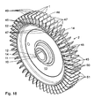
- shows a schematic view of a non-inventive impeller according to a seventh embodiment;
- Fig. 17
- shows a substantially rear view of an impeller blade of the im- peller shown in
Fig. 16 ; and - Fig. 18
- shows a schematic view of an inventive impeller according to an eighth embodiment.
- A side channel compressor shown in
Figs. 1 to 3 for compressing a gas comprises animpeller 2 which is provided withimpeller blades 1 and is mounted in ahousing 3 for rotation about a horizontal centrallongitudinal axis 4. Aconventional drive 6 serves for rotary drive of theimpeller 2 in the direction of thearrow 5. The gas is thus transported through thehousing 3 in the direction of thearrow 5 as well. - The
housing 3 comprises ahousing body 7 and ademountable housing cover 8 which are joined together according toFigs. 1 and2 so as to enclose theimpeller 2 comprising theimpeller blades 1 which is drivable for rotation and is disposed on adrive shaft 9 for co-rotation therewith. - The
impeller 2 is provided with a single blade ring and is designed like a disk. Theimpeller 2 comprises aninner impeller hub 10 with a centralcircular hub bore 11. Theimpeller hub 10 is formed by aninner hub foot 12 which radially outwardly delimits thehub bore 11, and by a radial circular hub washer 13 adjoining thehub foot 12. Moreover, theimpeller 2 comprises a radialouter carrier ring 14 which adjoins the outside of the hub washer 13 and overlaps with both sides of said hub washer 13 in the direction of the centrallongitudinal axis 4. Thecarrier ring 14 carries a multitude of radially projectingimpeller blades 1 which are distributed in the circumferential direction. In this embodiment, a total of 52individual impeller blades 1 are provided which are preferably arranged equidistantly so as to have an angular distance from one another, relative to the centrallongitudinal axis 4, that amounts to approximately 7°. Thus, 6 to 7impeller blades 1 are disposed at every 45°. Thehub foot 12, thehub washer 13 and thecarrier ring 14 form an integral cast part. - The terms "axial" and "radial" used in-here are relative to the central
longitudinal axis 4. The terms "inner" and "outer" are relative to the centrallongitudinal axis 4 as well. The term "inner" means that an inner region is nearer to the centrallongitudinal axis 4 than an outer region. - The central hub bore 11 may receive the
drive shaft 9. A conventional parallel-key connection is provided between thedrive shaft 9 and thehub foot 12 so as to transmit the torque generated by thedrive shaft 9 to theimpeller hub 10 for rotating theimpeller 2. - The
housing body 7 comprises acentral hub portion 15 which radially and axially delimits a partialhub receiving space 16. A central shaft bore 17 passes through thehub portion 15 and opens into the partialhub receiving space 16. Anannular side wall 18 adjoins thehub portion 15, saidannular side wall 18 extending radially outwardly from thehub portion 15. Acircumferential channel portion 19 adjoins the outside of theside wall 18. Thehub portion 15, theside wall 18 and thechannel portion 19 form an integral cast part which forms thehousing body 7.Rib webs 20 extending in a spoke-like manner are provided on the outside of thehousing body 7 which considerably increase the stability of thehousing body 7. Moreover,screw bosses 21 project radially outwardly from theside wall 18. - The
housing cover 8 is secured to thehousing body 7 by means of several connectingscrews 22 and comprises acentral hub portion 23 which radially and axially delimits a partialhub receiving space 24. A radially outwardly extendingannular side wall 25 adjoins thehub portion 23. Acircumferential channel portion 26 is attached to the outside of theside wall 25. A rolling-element bearing 27 for thedrive shaft 9 is disposed in thehub portion 23. Thehub portion 23, theside wall 25 and thechannel portion 26 form an integral cast part which forms thehousing cover 8. Likewise,rib webs 28 extending in a spoke-like manner also project from the outside of theside wall 25 so as to reinforce thehousing cover 8. - The
housing body 7 and thehousing cover 8 are joined together such that the two partialhub receiving spaces hub receiving space 29 between each other, and the twochannel portions side channel 30 between each other for compression of the gas. The twoside walls side channel 30, which is spaced from the centrallongitudinal axis 4, extends annularly about the centrallongitudinal axis 4 and is delimited by thechannel portions - An axial gas inlet opening 31 projecting into the
side channel 30 is formed at the bottom of thehousing cover 8. Further provided at the bottom of thehousing cover 8 is an axial gas outlet opening 32 which is in flow connection with theside channel 30 as well and is adjacent to thegas inlet opening 31. A projectinggas inlet connector 33 is connected to the gas inlet opening 31 while agas outlet connector 34 projecting in a likewise manner is connected to thegas outlet opening 32. Aninterceptor 35 is disposed in theside channel 30 between the gas inlet opening 31 and thegas outlet opening 32. - The
hub foot 12 of theimpeller 2 is disposed in thehub receiving space 29 defined by thehub portions drive shaft 9 passing through the hub bore 17. Thedrive shaft 9 is provided with afree bearing journal 36 at its end which is mounted for rotation in the rolling element bearing 27 in thehousing cover 8. The rolling element bearing 27 is provided with aninner ring 37 connected to thebearing journal 36 and anouter ring 38 connected to thehousing cover 8, with the rings being separated by rolling elements - in the shape of bearing balls 39 - disposed therebetween. Theinner ring 37 is shrunk onto the bearingjournal 36 for co-rotation therewith while theouter ring 38 is attached to thehousing cover 8 in a non-rotational manner. Thehub washer 13 of theimpeller 2 extends radially outwardly from thehub foot 12 between the spaced-apartside walls housing 3. Thecarrier ring 14 and theimpeller blades 1 are located in thecircumferential side channel 30. A certain portion of the foot of thecarrier ring 14 is positioned in an outwardlyopen recess 40 which is formed in thechannel portions side walls - The
side channel 30 has a free cross-sectional area which is available for transporting the gas and is approximately perpendicular to thearrow 5. Said cross-sectional area tapers from a cross-sectional area A E at the gas inlet opening 31 to a cross-sectional area A A at the gas outlet opening 32 such that A A < A E. Theside channel 30 may however have a constant cross-sectional area as well. - The
side channel 30 has a radial height S. Thedrive 6 is an electric motor which is detachably connected to the outside of thehousing body 7. To this end, several fastening screws are provided which are screwed in thescrew bosses 21 at thehousing body 7. - In order to ensure that the unit formed by the side channel compressor and the
drive 6 is securely installed,support feet 41 are formed at the bottom of the side channel compressor whilesupport feet 43 are formed at the bottom of acarrier body 42 as well, wherein thecarrier body 42 is connected to thehousing body 7 by means of screws and carries thedrive 6. - A vertical plane E runs through the central
longitudinal axis 4 and intersects the side channel compressor in a vertically symmetrical manner or centrally along the length, respectively. - The
impeller blades 1 according to a first embodiment are now described in more detail by means ofFigs. 4 and 5 . Eachimpeller blade 1 is substantially designed like a plate and has a substantially rectangular shape with a corresponding contour. Theimpeller blades 1 are designed identically and symmetrically relative to a symmetry plane X which is oriented perpendicular relative to the vertical plane E and runs through the center of thehub washer 13. Eachimpeller blade 1 further has an edge which is composed of a radiallyouter edge region 45, a radiallyinner edge region 46 opposite thereto, andlateral edge regions 47 inter-connecting the outer and inner edge regions. Theinner edge region 46 is in direct connection with thecarrier ring 14 and may also be regarded as the foot area of theimpeller blade 1 while the entire edge region 45 - which may be regarded as the head area of the impeller blade 1 - is entirely located in theside channel 30 and is oriented substantially parallel to the centrallongitudinal axis 4. Thelateral edge regions 47 are substantially parallel to each other and extend substantially radially outwardly from theinner edge region 46. Theedge regions inner edge region 46, on the other hand, is not free as it is adjoined by thecarrier ring 14. Theedge regions front surface 48 facing in the direction of thearrow 5 and arear surface 49 opposite thereto, thus facing in the opposite direction of thearrow 5. Eachimpeller blade 1 further comprises aninner edge portion 50 adjoining theinner edge region 46 and anouter edge portion 51 adjoining theouter edge region 45. Theinner edge portion 50 extends radially outwardly from theinner edge region 46, while theouter edge portion 51 is slightly inclined forwardly in the direction of thearrow 5 relative to theinner edge portion 50 for reasons of flow. Theouter edge portion 51 also reduces in thickness towards theouter edge region 45 when seen in the circumferential direction. - The distance between the
outer edge region 45 and theinner edge region 46 defines a radial height H of animpeller blade 1, wherein the radial height H of theinner edge portion 50 preferably amounts to between 55% and 75% of the radial height H. The radial height H is present near thelateral edge regions 47. Furthermore, eachimpeller blade 1 has an axial width B which is defined by the distances between theopposite edge regions 47. - The radial height H of an
impeller blade 1 is smaller than the radial depth S of theside channel 30. The radial height H amounts to between approximately 50% and 75%, preferably to approximately 60%, of the radial depth S of theside channel 30. Moreover, the axial width B of animpeller blade 1 is always considerably smaller than the corresponding axial width of theside channel 30. - In this embodiment, the
lateral edge regions 47 of animpeller blade 1 are in each case further equipped with areduction groove 52 having a substantially rectangular cross-section, wherein saidreduction groove 52 is axially outwardly open and is parallel to theouter edge region 45. Thesereduction grooves 52 are not shown inFigs. 1 to 3 . Eachreduction groove 52 opens into the correspondingfront surface 48 andrear surface 49 of animpeller blade 1, thus passing through the entire outer lateral side of theimpeller blade 1. Theopposite reduction grooves 52 are on a common level in theinner edge portion 50. They are located in the lower half of theinner edge portion 50 at a distance from theinner edge region 46, with each of the reduction grooves having a radial height A which amounts to between approximately 5% and 20%, preferably to between 10% and 15% of the radial height H of animpeller blade 1. The axial depth T of areduction groove 52 amounts to between approximately 2% and 12%, preferably to between 5% and 9%, of the axial width B of animpeller blade 1. - The following is a description of a non-inventive side channel compressor. The
drive shaft 9 is set in rotation about the centrallongitudinal axis 4 in the direction of thearrow 5 by means of thedrive 6. As it is coupled to thedrive shaft 9 for co-rotation therewith, theimpeller 2 comprising the impeller blades I therefore starts to rotate in the direction of thearrow 5 as well. Passing close to the gas inlet opening 31, theimpeller blades 1 draw the gas to be compressed intoside channel 30 through thegas inlet connector 33 and thegas inlet opening 31. The gas located in theside channel 30 is accelerated, by means of theimpeller blades 1, in the direction of thearrow 5 which may thus also be referred to as transport arrow. The front surfaces 48 of theimpeller blades 1 face forwardly in the direction of thearrow 5 and serve for the transport of the gas located in theside channel 30. During the transport, the gas is virtually trapped incells 44 which are inwardly delimited by thecarrier ring 14 and byadjacent impeller blades 1 in the circumferential direction. Acell 44 is in particular defined by thefront surface 48 of animpeller blade 1 and therear surface 49 of an impeller blade disposed adjacent thereto. Theedge regions - Due to the
reduction grooves 52, the respective surface area of thefront surfaces 48 andrear surfaces 49 of theimpeller blades 1 is smaller than that of conventional ungrooved impeller blades. Thereduction grooves 52 form flow channels, enabling a part of the gas to pass from one cell into another,downstream cell 44 which is located in the opposite direction of thearrow 5. Thereduction grooves 52 thus also act as lateral flow grooves through which a part of the gas can flow. Thesereduction grooves 52, or the amount of gas flowing through thesereduction grooves 52, respectively, lead to a reduction of gas turbulence structures at the trailing side of theimpeller blades 1. This in particular reduces the magnitude and intensity of the gas turbulence structures in theside channel 30 and consequently leads to a reduction of pressure variations. The operating noise of the side channel compressor is reduced as well. At the end of the circulation zone, the compressed gas is discharged from theside channel 30 via the gas outlet opening 32 and thegas outlet connector 34 by way of theimpeller blades 1. The angular path covered by the gas in the side channel compressor amounts to approximately 300°. The interceptor prevents the gas transported by theimpeller 2 from being carried over from the gas outlet opening 32 to the gas inlet opening 31 in theside channel 30. - The following is a description of a second non-inventive embodiment by means of
Figs. 6 and 7 . Identical parts are referred to with the same reference numerals as the first embodiment shown inFigs. 4 and 5 to the description of which reference is made. Parts that are different in design but have the same function are denoted by the same reference numerals with a subsequent a. Theimpeller 2a shown inFig. 6 differs from theimpeller 1 shown inFig. 4 with respect to itsimpeller blades 1a which are again symmetrical relative to the symmetry plane X. Unlike theimpeller blades 1 according toFigs. 4 and 5 , theimpeller blades 1a are provided with two spaced-apart,identical reduction grooves 52 in eachedge region 47a, saidreduction grooves 52 being parallel to each other and to theouter edge region 45. Thereduction grooves 52 are in each case located in theinner edge portion 50 and are disposed one above the other. They pass through theentire impeller blade 1 again, thus virtually forming flow channels. Thelower reduction groove 52 is disposed at a distance from thelower edge region 46 while theupper reduction groove 52 is disposed at a distance from theedge portion 51. As far as design, dimension and function of thereduction grooves 52 are concerned, reference is made to the aforementioned embodiment. Compared to the aforementioned embodiment, i.e. compared to theimpeller blades 1 according to the first embodiment, thesurfaces impeller blades 1a are even smaller, and due to the doubling of thereduction grooves 52, approximately twice the amount of gas is able to flow fromcell 44 tocell 44. The gas turbulence structures at the trailing side are reduced even more. - The following is a description of a third non-inventive embodiment by means of
Figs. 8 and 9 . Identical parts are referred to with the same reference numerals as the second embodiment shown inFigs. 6 and 7 to the description of which reference is made. Parts that are different in design but have the same function are denoted by the same reference numerals with a subsequent b. Unlike the aforementioned embodiment shown inFigs. 6 and 7 , this embodiment is provided with areduction groove 52 in theouter edge portion 51b as well. Eachedge region 47b is provided with a total of threeidentical reduction grooves 52 which are in each case spaced from each other. They are parallel to each other and to theouter edge region 45. Theupper reduction groove 52 in theedge portion 51b is disposed at a distance from theouter edge region 45. Thereduction grooves 52 are disposed one above the other at identical distances relative to each other. Theimpeller blades 1b are again symmetrical relative to the symmetry plane X. As far as dimensioning, design and function of thereduction grooves 52 are concerned, reference is made to the aforementioned embodiment. Compared to the second embodiment, turbulence structures at the trailing side are reduced even more as theadditional reduction grooves 52 make thesurfaces reduction grooves 52. - The following is a description of a fourth non-inventive embodiment of the invention by means of
Figs. 10 and 11 . Identical parts are referred to with the same reference numerals as the third embodiment shown inFigs. 8 and 9 to the description of which reference is made. Parts that are different in design but have the same function are denoted by the same reference numerals with a subsequent c. The only difference to the third embodiment according to theFigs. 8 and 9 is that thereduction grooves 52c have a semi-circular cross-section instead of a rectangular one. They are again axially outwardly open and pass through theentire impeller blades 1c. They are disposed one above the other and have a maximum depth that is equal to depth T. Their maximum outside height is approximately equal to height A. As far as position and function of thereduction grooves 52c are concerned, reference is made to the third embodiment. In this embodiment, theimpeller blades 1c are subject to a particularly low notch effect.Semi-circular reduction grooves 52c are also suitable for the first and second embodiments. - The following is a description of a fifth non-inventive embodiment by means of
Figs. 12 and 13 . Identical parts are referred to with the same reference numerals as the first embodiment shown inFigs. 4 and 5 to the description of which reference is made. Parts that are different in design but have the same function are denoted by the same reference numerals with a subsequent d. Unlike the first embodiment shown inFigs. 4 and 5 , thelateral edge regions 47d are not provided with reduction grooves. Instead, theouter edge region 45d is provided with four spaced-apart,identical reduction grooves 52 that pass through theentire impeller blade 1d and are disposed next to each other. In this embodiment, thereduction grooves 52, which form flow channels, are located in theouter edge portion 51 only and have a radial depth that is substantially equal to depth T. Their width is also substantially equal to height A so that the cross-sectional area of areduction groove 52 is thus equal to the cross-sectional area of areduction groove 52 shown inFigs. 4 and 5 . Thereduction grooves 52 have a rectangular cross-section and are radially outwardly open. They have an identical distance from each other. Theimpeller blades 1d are designed symmetrically relative to the plane X. This design reduces gas turbulence structures at the trailing side as well. As far as dimensioning and shape of thereduction grooves 52 are concerned, reference is made to the first embodiment. Instead of the fourreduction grooves 52, only onecentral reduction groove 52 may be provided. However, eachimpeller blade 1d may also be provided with two or three or evenmore reduction grooves 52, which should then also be disposed in a preferably symmetrical manner. Instead of the rectangular shape shown here, other shapes are applicable as well, such as a semi-circular shape. - The following is a description of a sixth non-inventive embodiment by means of
Figs. 14 and 15 . Identical parts are referred to with the same reference numerals as the third or fifth embodiments, respectively, shown inFigs. 8 and 9 as well asFigs. 12 and 13 to the description of which reference is made. Parts that are different in design but have the same function are denoted by the same reference numerals with a subsequent e. Thisimpeller 2e hasimpeller blades 1e which are substantially a combination of theimpeller blades Figs. 8, 9 and12, 13 . In this embodiment, eachimpeller blade 1e has three spaced-apartreduction grooves 52 disposed one above the other in eachlateral edge region 47b and four spaced-apartreduction grooves 52 disposed in succession in the radialouter edge region 45d of the impeller blade. As far as dimensioning, position and shape of thereduction grooves 52 are concerned, reference is made to the first, third and fifth embodiments. In this embodiment, each of thefree edge regions reduction grooves 52 is provided and thesurfaces impeller blades 1e are again symmetrical relative to the symmetry plane X. Alternatively, thesemi-circular reduction grooves 52c are also applicable in this embodiment. Furthermore, each of theedge regions 45d and/or 47b may be provided with a different number ofreduction grooves 52. - An axially lateral and/or radially outer grooving of the impeller blades reduces the front and rear surfaces thereof by forming flow channels, thus reducing turbulence structures at the trailing side. The reduction grooves may be of any desired shape. To this end, each impeller blade is provided with at least one reduction groove. Each of the lateral edge regions and/or the radially outer edge regions may be provided with any desired number of grooves. One and the same impeller blade may also be provided with reduction grooves of different shapes. Each lateral edge region and/or each outer edge region is provided with at least one reduction groove, wherein the actual number of which in the respective edge regions may be randomly selected and may be different from one edge region to the next. A symmetrical design of the impeller blades or a symmetrical arrangement of the reduction grooves, respectively, is preferred.
- As a non-inventive alternative to the described grooves, the lateral edge regions can also be chamfered, in other words they can have set-back blade edges, and/or the radially outer edge regions can be chamfered as well. These chamfers form flow recesses again that reduce the front and/or rear surfaces of the impeller blades so that turbulence structures at the trailing side are reduced to a minimum. The lateral flow recesses may be oriented such that the impeller blades become larger or smaller from their front surfaces towards their rear surfaces. The impeller blades or lateral edge regions, respectively, may also converge upwardly or radially outwardly, respectively, such that the outer edge portion has a substantially trapezoidal shape, for instance. In that case, flow recesses are thus provided both radially and laterally.
- The following is a description of a seventh non-inventive embodiment by means of
Figs. 16 and 17 . Identical parts are referred to with the same ref erence numerals as the first embodiment to the description of which reference is made. Parts that are different in design but have the same function are denoted by the same reference numerals with a subsequent f. In all aforementioned embodiments, theimpeller 2 has a single blade ring. In this embodiment on the other hand, theimpeller 2f is configured as a double blade ring with another,outer carrier ring 53 which delimits thecells 44 radially outwardly and adjoins theouter edge region 45f of theimpeller blades 1f. Otherwise, there are no major differences compared to the first embodiment. Theindividual impeller blades 2f are again symmetrical relative to a symmetry plane X. As in the first embodiment, eachedge region 47f of this embodiment is provided with areduction groove 52. Thereduction grooves 52 are adjacent to the corresponding edge region 46f. As far as shape, dimensioning and position of saidreduction grooves 52 are concerned, reference is made to the first embodiment. According to alternative embodiments, each of thelateral edge regions 47f is provided with more than onereduction groove 52. Alternatively, thereduction grooves 52 are again so designed as to have a different, for instance a semi-circular, cross-section. Again, other recesses, such as chamfers, in theedge regions 47f are conceivable as well. - The following is description of an eighth embodiment of the invention by means of
Fig 18 . Identical parts are referred to with the same reference numerals as the embodiment shown inFigs. 4 and 5 to the description of which reference is made. Unlike the first embodiment, not all of theimpeller blades 1 of this embodiment are grooved in thelateral edge regions 47 but only 30% to 70%, preferably 40% to 60%, of all impeller blades. In this embodiment,impeller blades 1 withreduction grooves 52 according to the first embodiment are disposed between impeller blades without reduction grooves. Thegrooved impeller blades 1 are disposed randomly, i.e. stochastically. As shown at the top ofFig. 18 , three regular, i.e. ungrooved impeller blades are provided between twogrooved impeller blades 1. At the upper lateral sides on the other hand, only two regular impeller blades are provided between twogrooved impeller blades 1. It is however also conceivable to arrange twogrooved impeller blades 1 directly behind each other. In this embodiment, thereduction grooves 52 act as reducing grooves for reducing periodic flow structures. This prevents formation of regular, harmonic flow structures, thus ensuring a particularly silent operation of the side channel compressor. Again, the gas turbulence structures at the trailing side are reduced as well. - Instead of the
impeller blades 1 described here according to the embodiment shown inFigs. 4 and 5 , the other aforementioned impeller blades are applicable as well. Also, several different impeller blades of the aforementioned embodiments may be provided in one and the same impeller. Sequence repetitions are possible. Alternatively, identically grooved impeller blades may be provided several times in a row. The sequence is thus completely random. What is essential is that the impeller blades are designed differently, for instance in terms of their shape and/or size. The impeller blades can also only differ in height and/or width. They are preferably disposed equidistantly. - The side channel compressor may comprise at least one stationary projection for engaging with the at least one flow recess or
reduction groove reduction groove - The
interceptor 35 for theimpeller impeller reduction groove impeller blades interceptor 35 is provided for each flow recess orreduction groove interceptor 35 for theimpeller 2 has one projection. Theinterceptor 35 for theimpeller 2a has two separate projections. Theinterceptors 35 for theimpellers impeller 2f has one projection. The size and the design of the projections are adapted to the size and the design of the flow recesses orreduction grooves reduction groove - According to a further embodiment, there is at least one projection on the
housing 3 which projects towards theimpeller reduction groove reduction grooves reduction grooves - The at least one projection may have an elongate curved form which is concentric to the
longitudinal axis 4.
Claims (12)
- A side channel compressor for compressing a gas comprising:a) a housing (3),b) a side channel (30) located in the housing (3) for compressing a gas,c) a gas inlet opening (31) formed in the housing (3) which is in flow connection with the side channel (30) for introducing a gas to be compressed,d) a gas outlet opening (32) formed in the housing (3) for discharging the gas to be compressed from the side channel (30), the gas outlet opening (32) being in flow connection with the gas inlet opening (31) by way of the side channel (30), ande) an impeller (2; 2a; 2b; 2c; 2d; 2e; 2f) which is mounted for rotary drive in the housing (3) and has at least two impeller blades (1; 1a; 1c; 1d; 1e; 1f) disposed in the side channel (30),f) wherein at least one impeller blade (1; 1a; 1b; 1c; 1d; 1e; 1f) has at least one flow recess (52, 52c) in its free edge region (45d; 47; 47a; 47b; 47c; 47f); the compressor being characterised in that the at least one flow recess (52; 52c) is a flow groove having a substantially rectangular cross-section, and that only 30 % to 70 % of all impeller blades (1) are grooved.
- A side channel compressor according to claim 1, wherein each impeller blade (1; 1a; 1b; 1c; 1d; 1e; 1f) has lateral edges (47; 47a; 47b; 47c; 47d; 47f), wherein the lateral edges (47; 47a; 47b; 47c; 47d; 47f) are provided with flow recesses (52, 52c) so as to reduce gas turbulence structures.
- A side channel compressor according to claim 2, wherein each lateral edge (47; 47a; 47b; 47c; 47f) is provided with at least one flow recess (52, 52c).
- A side channel compressor according to claim 1, wherein each impeller blade (1; 1a; 1b; 1c; 1d; 1e; 1f) has a head edge (45; 45d), the head edges (45d) being provided with flow recesses (52; 52c) for reducing gas turbulence structures.
- A side channel compressor according to claim 1, wherein at least two impeller blades (1; 1a; 1b; 1c; 1d; 1e; 1f) differ from each other so as to reduce periodic flow structures.
- A side channel compressor according to claim 5, wherein each impeller blade (1; 1a; 1b; 1c; 1d; 1e; 1f) has a head edge (45d), wherein the at least two impeller blades (1; 1a; 1b; 1c; 1d; 1e; 1f) differ in terms of their head edges (45; 45d).
- A side channel compressor according to claim 6, wherein the head edges (45; 45d) differ in terms of flow recesses (52; 52c).
- A side channel compressor according to claim 5, wherein the impeller blades (1; 1a; 1b; 1c; 1d; 1e;...; 1f) have lateral edges (47; 47a; 47b; 47c; 47d; 47f), wherein the at least two impeller blades (1; 1a; 1b; 1c; 1d; 1e; 1f) differ in terms of their lateral edges (47; 47a; 47b; 47c; 47d; 47f).
- A side channel compressor according to claim 8, wherein the lateral edges (47; 47a; 47b; 47c; 47d; 47f) differ in terms of flow recesses (52; 52c).
- A side channel compressor according to claim 5, wherein the impeller blades differ in terms of their size.
- A side channel compressor according to claim 5, wherein the different impeller blades (1; 1a; 1b; 1c; 1d; 1e; 1f) are disposed in a random sequence.
- A side channel compressor according to claim 1, comprising at least one stationary projection for engaging with the at least one flow recess (52, 52c).
Applications Claiming Priority (2)
| Application Number | Priority Date | Filing Date | Title |
|---|---|---|---|
| DE102007053017A DE102007053017A1 (en) | 2007-11-05 | 2007-11-05 | Side Channel Blowers |
| PCT/EP2008/009119 WO2009059718A1 (en) | 2007-11-05 | 2008-10-29 | Side channel compressor |
Publications (2)
| Publication Number | Publication Date |
|---|---|
| EP2207967A1 EP2207967A1 (en) | 2010-07-21 |
| EP2207967B1 true EP2207967B1 (en) | 2011-05-11 |
Family
ID=40451334
Family Applications (1)
| Application Number | Title | Priority Date | Filing Date |
|---|---|---|---|
| EP08847294A Not-in-force EP2207967B1 (en) | 2007-11-05 | 2008-10-29 | Side channel compressor |
Country Status (10)
| Country | Link |
|---|---|
| US (1) | US20100221097A1 (en) |
| EP (1) | EP2207967B1 (en) |
| KR (1) | KR101485622B1 (en) |
| CN (1) | CN101849110B (en) |
| AT (1) | ATE509203T1 (en) |
| DE (1) | DE102007053017A1 (en) |
| DK (1) | DK2207967T3 (en) |
| ES (1) | ES2365479T3 (en) |
| TW (1) | TW200936887A (en) |
| WO (1) | WO2009059718A1 (en) |
Cited By (1)
| Publication number | Priority date | Publication date | Assignee | Title |
|---|---|---|---|---|
| DE102012023347B3 (en) * | 2012-11-29 | 2014-01-30 | Tni Medical Ag | Small, quiet side channel blower, especially for devices in ventilation therapy |
Families Citing this family (20)
| Publication number | Priority date | Publication date | Assignee | Title |
|---|---|---|---|---|
| DE102011004512A1 (en) * | 2011-02-22 | 2012-08-23 | Gardner Denver Deutschland Gmbh | Side channel machine arrangement |
| CN102538431A (en) * | 2012-02-23 | 2012-07-04 | 谭锐 | Safety type intelligent and efficient drying fan |
| JP2013245574A (en) * | 2012-05-24 | 2013-12-09 | Calsonic Kansei Corp | Vane rotary type gas compressor |
| DE102013220668A1 (en) | 2013-10-14 | 2015-04-16 | Continental Automotive Gmbh | Impeller for a particular designed as a side channel blower side channel flow machine |
| DE102014106440A1 (en) * | 2014-05-08 | 2015-11-12 | Gebr. Becker Gmbh | Impeller, in particular for a side channel machine |
| DE102015202947A1 (en) * | 2015-02-18 | 2016-08-18 | Mahle International Gmbh | Pumping device for driving blow-by gas |
| DE102015202943A1 (en) * | 2015-02-18 | 2016-08-18 | Mahle International Gmbh | Pumping device for driving blow-by gas |
| DE102015202948A1 (en) * | 2015-02-18 | 2016-08-18 | Mahle International Gmbh | Pumping device for driving blow-by gas |
| DE102015202946A1 (en) * | 2015-02-18 | 2016-08-18 | Mahle International Gmbh | Pumping device for driving blow-by gas |
| DE102015209561A1 (en) * | 2015-05-26 | 2016-12-01 | Mahle International Gmbh | Pumping device and crankcase ventilation device |
| CN105114186B (en) * | 2015-08-04 | 2017-03-29 | 西北工业大学 | A kind of leaf cellular type preswirl nozzle for cooling system of prewhirling |
| EP3199818A1 (en) * | 2016-01-29 | 2017-08-02 | ESAM S.p.A. | Side-channel blower/aspirator with an improved impeller |
| DE102017215731A1 (en) * | 2017-09-07 | 2019-03-07 | Robert Bosch Gmbh | Side channel compressor for a fuel cell system for conveying and / or compressing a gaseous medium |
| DE102017215739A1 (en) | 2017-09-07 | 2019-03-07 | Robert Bosch Gmbh | Side channel compressor for a fuel cell system for conveying and / or compressing a gaseous medium |
| TWI663339B (en) | 2017-10-26 | 2019-06-21 | 宏碁股份有限公司 | Heat dissipation fan |
| DE102017220623A1 (en) * | 2017-11-17 | 2019-05-23 | Robert Bosch Gmbh | Side channel compressor for a fuel cell system for conveying and / or sealing a gaseous medium |
| DE102018204713A1 (en) * | 2018-03-28 | 2019-10-02 | Robert Bosch Gmbh | Side channel compressor for a fuel cell system for conveying and / or compressing a gaseous medium |
| DE102019120410A1 (en) * | 2019-07-29 | 2021-02-04 | Schwäbische Hüttenwerke Automotive GmbH | Conveyor device with a side channel or peripheral fan |
| CN110454433B (en) * | 2019-08-27 | 2024-04-05 | 陕西科技大学 | Impeller structure for submersible pump |
| TWI726684B (en) * | 2020-04-15 | 2021-05-01 | 宏碁股份有限公司 | Fan |
Family Cites Families (16)
| Publication number | Priority date | Publication date | Assignee | Title |
|---|---|---|---|---|
| US3347520A (en) * | 1966-07-12 | 1967-10-17 | Jerzy A Oweczarek | Turbomachine blading |
| US3951567A (en) * | 1971-12-18 | 1976-04-20 | Ulrich Rohs | Side channel compressor |
| DE2738208B1 (en) * | 1977-08-24 | 1978-05-11 | Siemens Ag | Side channel blower |
| DE3939957A1 (en) * | 1989-12-02 | 1991-06-06 | Webasto Ag Fahrzeugtechnik | Side channel blower system - has rotor blades, each with helical surface |
| DE4244458A1 (en) * | 1991-12-27 | 1993-07-01 | Mitsubishi Electric Corp | Electric pump supplying by=pass air to vehicle catalytic converters - circulates air inside motor case for cooling of motor, and has noise absorbers in air suction port |
| US5584653A (en) * | 1992-09-08 | 1996-12-17 | J. Eberspacher | Device for reducing the generation of noise in fans |
| KR970011415A (en) * | 1996-12-11 | 1997-03-27 | 조봉현 | Unbalanced Vane Pump |
| KR200345962Y1 (en) | 1997-12-29 | 2004-06-17 | 삼성테크윈 주식회사 | Air cooling apparatus for turbo engine |
| DE19906130A1 (en) * | 1999-02-13 | 2000-08-17 | Mannesmann Vdo Ag | Feed pump |
| DE19955955A1 (en) * | 1999-11-19 | 2001-06-13 | Siemens Ag | Side channel machine e.g. high power fan |
| JP2004353496A (en) * | 2003-05-28 | 2004-12-16 | Sony Corp | Thin fan motor |
| DE10334812A1 (en) * | 2003-07-30 | 2005-03-03 | J. Eberspächer GmbH & Co. KG | Blower, in particular combustion air blower for a vehicle heater and method for operating the blower |
| DE10344719A1 (en) * | 2003-09-26 | 2005-05-04 | Elektror M Mueller Gmbh | Side channel compressor with an annular impeller housing |
| US7033137B2 (en) * | 2004-03-19 | 2006-04-25 | Ametek, Inc. | Vortex blower having helmholtz resonators and a baffle assembly |
| DE102005062585B3 (en) * | 2005-12-27 | 2007-07-05 | J. Eberspächer GmbH & Co. KG | Fluid delivery device, in particular side channel blower |
| US7722311B2 (en) * | 2006-01-11 | 2010-05-25 | Borgwarner Inc. | Pressure and current reducing impeller |
-
2007
- 2007-11-05 DE DE102007053017A patent/DE102007053017A1/en not_active Ceased
-
2008
- 2008-10-29 WO PCT/EP2008/009119 patent/WO2009059718A1/en not_active Ceased
- 2008-10-29 DK DK08847294.9T patent/DK2207967T3/en active
- 2008-10-29 ES ES08847294T patent/ES2365479T3/en active Active
- 2008-10-29 US US12/681,523 patent/US20100221097A1/en not_active Abandoned
- 2008-10-29 AT AT08847294T patent/ATE509203T1/en not_active IP Right Cessation
- 2008-10-29 EP EP08847294A patent/EP2207967B1/en not_active Not-in-force
- 2008-10-29 KR KR1020107010043A patent/KR101485622B1/en not_active Expired - Fee Related
- 2008-10-29 CN CN200880114661XA patent/CN101849110B/en not_active Expired - Fee Related
- 2008-11-05 TW TW097142715A patent/TW200936887A/en unknown
Cited By (3)
| Publication number | Priority date | Publication date | Assignee | Title |
|---|---|---|---|---|
| DE102012023347B3 (en) * | 2012-11-29 | 2014-01-30 | Tni Medical Ag | Small, quiet side channel blower, especially for devices in ventilation therapy |
| WO2014082892A1 (en) | 2012-11-29 | 2014-06-05 | Tni Medical Ag | Small, low-noise side channel compressor, in particular for devices in ventilation therapy |
| US10532169B2 (en) | 2012-11-29 | 2020-01-14 | Tni Medical Ag | Small, low-noise side channel compressor, in particular for devices in ventilation therapy |
Also Published As
| Publication number | Publication date |
|---|---|
| WO2009059718A1 (en) | 2009-05-14 |
| CN101849110A (en) | 2010-09-29 |
| EP2207967A1 (en) | 2010-07-21 |
| KR20100091961A (en) | 2010-08-19 |
| US20100221097A1 (en) | 2010-09-02 |
| CN101849110B (en) | 2012-11-07 |
| TW200936887A (en) | 2009-09-01 |
| ES2365479T3 (en) | 2011-10-06 |
| KR101485622B1 (en) | 2015-01-22 |
| DK2207967T3 (en) | 2011-08-15 |
| ATE509203T1 (en) | 2011-05-15 |
| DE102007053017A1 (en) | 2009-05-07 |
Similar Documents
| Publication | Publication Date | Title |
|---|---|---|
| US20100221097A1 (en) | Side channel compressor | |
| EP2205875B1 (en) | Side channel compressor | |
| US9157452B2 (en) | Radial fan wheel, fan unit and radial fan arrangement | |
| US7338251B2 (en) | Turbo compressor | |
| CN104813082B (en) | Seals and rotating machinery | |
| US20050019152A1 (en) | Recirculation structure for a turbocompressor | |
| US20120257957A1 (en) | Counter-rotating axial flow fan | |
| US10119546B2 (en) | Rotary machine | |
| US10605264B2 (en) | Diffuser, airflow generating apparatus, and electrical device | |
| WO2017138199A1 (en) | Centrifugal compressor | |
| US20110142614A1 (en) | Counter-rotating axial flow fan | |
| JP2014074360A (en) | Centrifugal compressor | |
| US20180017069A1 (en) | Side-channel blower for an internal combustion engine | |
| US12060887B2 (en) | Fan with cover plate on the rotor bell | |
| KR20150037589A (en) | Centrifugal impeller and centrifugal blower | |
| US6296439B1 (en) | Regenerative turbine pump impeller | |
| US7390162B2 (en) | Rotary ram compressor | |
| US20170350410A1 (en) | Centrifugal compressor impeller | |
| JP4696774B2 (en) | Double suction centrifugal pump | |
| US7445422B2 (en) | Hybrid turbomolecular vacuum pumps | |
| US7645116B2 (en) | Turbo vacuum pump | |
| JP2026032671A (en) | centrifugal pump | |
| KR20110101982A (en) | Turbo compressor with impeller with shroud splitter | |
| TW202603284A (en) | Magnetic levitation type pump | |
| US20170107820A1 (en) | Turbine wheel for a radial turbine |
Legal Events
| Date | Code | Title | Description |
|---|---|---|---|
| PUAI | Public reference made under article 153(3) epc to a published international application that has entered the european phase |
Free format text: ORIGINAL CODE: 0009012 |
|
| 17P | Request for examination filed |
Effective date: 20100417 |
|
| AK | Designated contracting states |
Kind code of ref document: A1 Designated state(s): AT BE BG CH CY CZ DE DK EE ES FI FR GB GR HR HU IE IS IT LI LT LU LV MC MT NL NO PL PT RO SE SI SK TR |
|
| AX | Request for extension of the european patent |
Extension state: AL BA MK RS |
|
| GRAP | Despatch of communication of intention to grant a patent |
Free format text: ORIGINAL CODE: EPIDOSNIGR1 |
|
| DAX | Request for extension of the european patent (deleted) | ||
| GRAS | Grant fee paid |
Free format text: ORIGINAL CODE: EPIDOSNIGR3 |
|
| GRAA | (expected) grant |
Free format text: ORIGINAL CODE: 0009210 |
|
| AK | Designated contracting states |
Kind code of ref document: B1 Designated state(s): AT BE BG CH CY CZ DE DK EE ES FI FR GB GR HR HU IE IS IT LI LT LU LV MC MT NL NO PL PT RO SE SI SK TR |
|
| REG | Reference to a national code |
Ref country code: GB Ref legal event code: FG4D |
|
| REG | Reference to a national code |
Ref country code: CH Ref legal event code: EP |
|
| REG | Reference to a national code |
Ref country code: IE Ref legal event code: FG4D |
|
| REG | Reference to a national code |
Ref country code: DE Ref legal event code: R096 Ref document number: 602008006925 Country of ref document: DE Effective date: 20110622 |
|
| REG | Reference to a national code |
Ref country code: DK Ref legal event code: T3 |
|
| REG | Reference to a national code |
Ref country code: NL Ref legal event code: VDEP Effective date: 20110511 |
|
| REG | Reference to a national code |
Ref country code: ES Ref legal event code: FG2A Ref document number: 2365479 Country of ref document: ES Kind code of ref document: T3 Effective date: 20111006 |
|
| PG25 | Lapsed in a contracting state [announced via postgrant information from national office to epo] |
Ref country code: NO Free format text: LAPSE BECAUSE OF FAILURE TO SUBMIT A TRANSLATION OF THE DESCRIPTION OR TO PAY THE FEE WITHIN THE PRESCRIBED TIME-LIMIT Effective date: 20110811 Ref country code: PT Free format text: LAPSE BECAUSE OF FAILURE TO SUBMIT A TRANSLATION OF THE DESCRIPTION OR TO PAY THE FEE WITHIN THE PRESCRIBED TIME-LIMIT Effective date: 20110912 Ref country code: SE Free format text: LAPSE BECAUSE OF FAILURE TO SUBMIT A TRANSLATION OF THE DESCRIPTION OR TO PAY THE FEE WITHIN THE PRESCRIBED TIME-LIMIT Effective date: 20110511 Ref country code: LT Free format text: LAPSE BECAUSE OF FAILURE TO SUBMIT A TRANSLATION OF THE DESCRIPTION OR TO PAY THE FEE WITHIN THE PRESCRIBED TIME-LIMIT Effective date: 20110511 |
|
| PG25 | Lapsed in a contracting state [announced via postgrant information from national office to epo] |
Ref country code: BE Free format text: LAPSE BECAUSE OF FAILURE TO SUBMIT A TRANSLATION OF THE DESCRIPTION OR TO PAY THE FEE WITHIN THE PRESCRIBED TIME-LIMIT Effective date: 20110511 Ref country code: GR Free format text: LAPSE BECAUSE OF FAILURE TO SUBMIT A TRANSLATION OF THE DESCRIPTION OR TO PAY THE FEE WITHIN THE PRESCRIBED TIME-LIMIT Effective date: 20110812 Ref country code: CY Free format text: LAPSE BECAUSE OF FAILURE TO SUBMIT A TRANSLATION OF THE DESCRIPTION OR TO PAY THE FEE WITHIN THE PRESCRIBED TIME-LIMIT Effective date: 20110511 Ref country code: SI Free format text: LAPSE BECAUSE OF FAILURE TO SUBMIT A TRANSLATION OF THE DESCRIPTION OR TO PAY THE FEE WITHIN THE PRESCRIBED TIME-LIMIT Effective date: 20110511 Ref country code: IS Free format text: LAPSE BECAUSE OF FAILURE TO SUBMIT A TRANSLATION OF THE DESCRIPTION OR TO PAY THE FEE WITHIN THE PRESCRIBED TIME-LIMIT Effective date: 20110911 Ref country code: FI Free format text: LAPSE BECAUSE OF FAILURE TO SUBMIT A TRANSLATION OF THE DESCRIPTION OR TO PAY THE FEE WITHIN THE PRESCRIBED TIME-LIMIT Effective date: 20110511 Ref country code: LV Free format text: LAPSE BECAUSE OF FAILURE TO SUBMIT A TRANSLATION OF THE DESCRIPTION OR TO PAY THE FEE WITHIN THE PRESCRIBED TIME-LIMIT Effective date: 20110511 Ref country code: AT Free format text: LAPSE BECAUSE OF FAILURE TO SUBMIT A TRANSLATION OF THE DESCRIPTION OR TO PAY THE FEE WITHIN THE PRESCRIBED TIME-LIMIT Effective date: 20110511 |
|
| PG25 | Lapsed in a contracting state [announced via postgrant information from national office to epo] |
Ref country code: NL Free format text: LAPSE BECAUSE OF FAILURE TO SUBMIT A TRANSLATION OF THE DESCRIPTION OR TO PAY THE FEE WITHIN THE PRESCRIBED TIME-LIMIT Effective date: 20110511 |
|
| PG25 | Lapsed in a contracting state [announced via postgrant information from national office to epo] |
Ref country code: EE Free format text: LAPSE BECAUSE OF FAILURE TO SUBMIT A TRANSLATION OF THE DESCRIPTION OR TO PAY THE FEE WITHIN THE PRESCRIBED TIME-LIMIT Effective date: 20110511 Ref country code: CZ Free format text: LAPSE BECAUSE OF FAILURE TO SUBMIT A TRANSLATION OF THE DESCRIPTION OR TO PAY THE FEE WITHIN THE PRESCRIBED TIME-LIMIT Effective date: 20110511 |
|
| PG25 | Lapsed in a contracting state [announced via postgrant information from national office to epo] |
Ref country code: RO Free format text: LAPSE BECAUSE OF FAILURE TO SUBMIT A TRANSLATION OF THE DESCRIPTION OR TO PAY THE FEE WITHIN THE PRESCRIBED TIME-LIMIT Effective date: 20110511 Ref country code: PL Free format text: LAPSE BECAUSE OF FAILURE TO SUBMIT A TRANSLATION OF THE DESCRIPTION OR TO PAY THE FEE WITHIN THE PRESCRIBED TIME-LIMIT Effective date: 20110511 Ref country code: SK Free format text: LAPSE BECAUSE OF FAILURE TO SUBMIT A TRANSLATION OF THE DESCRIPTION OR TO PAY THE FEE WITHIN THE PRESCRIBED TIME-LIMIT Effective date: 20110511 |
|
| PLBE | No opposition filed within time limit |
Free format text: ORIGINAL CODE: 0009261 |
|
| STAA | Information on the status of an ep patent application or granted ep patent |
Free format text: STATUS: NO OPPOSITION FILED WITHIN TIME LIMIT |
|
| 26N | No opposition filed |
Effective date: 20120214 |
|
| PG25 | Lapsed in a contracting state [announced via postgrant information from national office to epo] |
Ref country code: HR Free format text: LAPSE BECAUSE OF FAILURE TO SUBMIT A TRANSLATION OF THE DESCRIPTION OR TO PAY THE FEE WITHIN THE PRESCRIBED TIME-LIMIT Effective date: 20111123 Ref country code: MC Free format text: LAPSE BECAUSE OF NON-PAYMENT OF DUE FEES Effective date: 20111031 |
|
| REG | Reference to a national code |
Ref country code: DE Ref legal event code: R097 Ref document number: 602008006925 Country of ref document: DE Effective date: 20120214 |
|
| REG | Reference to a national code |
Ref country code: IE Ref legal event code: MM4A |
|
| PG25 | Lapsed in a contracting state [announced via postgrant information from national office to epo] |
Ref country code: IE Free format text: LAPSE BECAUSE OF NON-PAYMENT OF DUE FEES Effective date: 20111029 |
|
| PG25 | Lapsed in a contracting state [announced via postgrant information from national office to epo] |
Ref country code: MT Free format text: LAPSE BECAUSE OF FAILURE TO SUBMIT A TRANSLATION OF THE DESCRIPTION OR TO PAY THE FEE WITHIN THE PRESCRIBED TIME-LIMIT Effective date: 20110511 |
|
| PG25 | Lapsed in a contracting state [announced via postgrant information from national office to epo] |
Ref country code: LU Free format text: LAPSE BECAUSE OF NON-PAYMENT OF DUE FEES Effective date: 20111029 |
|
| REG | Reference to a national code |
Ref country code: CH Ref legal event code: PL |
|
| PG25 | Lapsed in a contracting state [announced via postgrant information from national office to epo] |
Ref country code: BG Free format text: LAPSE BECAUSE OF FAILURE TO SUBMIT A TRANSLATION OF THE DESCRIPTION OR TO PAY THE FEE WITHIN THE PRESCRIBED TIME-LIMIT Effective date: 20110811 |
|
| PG25 | Lapsed in a contracting state [announced via postgrant information from national office to epo] |
Ref country code: LI Free format text: LAPSE BECAUSE OF NON-PAYMENT OF DUE FEES Effective date: 20121031 Ref country code: CH Free format text: LAPSE BECAUSE OF NON-PAYMENT OF DUE FEES Effective date: 20121031 |
|
| PG25 | Lapsed in a contracting state [announced via postgrant information from national office to epo] |
Ref country code: TR Free format text: LAPSE BECAUSE OF FAILURE TO SUBMIT A TRANSLATION OF THE DESCRIPTION OR TO PAY THE FEE WITHIN THE PRESCRIBED TIME-LIMIT Effective date: 20110511 |
|
| PG25 | Lapsed in a contracting state [announced via postgrant information from national office to epo] |
Ref country code: HU Free format text: LAPSE BECAUSE OF FAILURE TO SUBMIT A TRANSLATION OF THE DESCRIPTION OR TO PAY THE FEE WITHIN THE PRESCRIBED TIME-LIMIT Effective date: 20110511 |
|
| PG25 | Lapsed in a contracting state [announced via postgrant information from national office to epo] |
Ref country code: HR Free format text: LAPSE BECAUSE OF FAILURE TO SUBMIT A TRANSLATION OF THE DESCRIPTION OR TO PAY THE FEE WITHIN THE PRESCRIBED TIME-LIMIT Effective date: 20110511 |
|
| REG | Reference to a national code |
Ref country code: FR Ref legal event code: PLFP Year of fee payment: 8 |
|
| REG | Reference to a national code |
Ref country code: FR Ref legal event code: PLFP Year of fee payment: 9 |
|
| REG | Reference to a national code |
Ref country code: FR Ref legal event code: PLFP Year of fee payment: 10 |
|
| REG | Reference to a national code |
Ref country code: FR Ref legal event code: PLFP Year of fee payment: 11 |
|
| PGFP | Annual fee paid to national office [announced via postgrant information from national office to epo] |
Ref country code: IT Payment date: 20201023 Year of fee payment: 13 Ref country code: FR Payment date: 20201026 Year of fee payment: 13 Ref country code: GB Payment date: 20201027 Year of fee payment: 13 Ref country code: DE Payment date: 20201028 Year of fee payment: 13 Ref country code: ES Payment date: 20201103 Year of fee payment: 13 Ref country code: DK Payment date: 20201028 Year of fee payment: 13 |
|
| REG | Reference to a national code |
Ref country code: DE Ref legal event code: R082 Ref document number: 602008006925 Country of ref document: DE Representative=s name: MURGITROYD & COMPANY, DE |
|
| REG | Reference to a national code |
Ref country code: DE Ref legal event code: R119 Ref document number: 602008006925 Country of ref document: DE |
|
| REG | Reference to a national code |
Ref country code: DK Ref legal event code: EBP Effective date: 20211031 |
|
| GBPC | Gb: european patent ceased through non-payment of renewal fee |
Effective date: 20211029 |
|
| PG25 | Lapsed in a contracting state [announced via postgrant information from national office to epo] |
Ref country code: GB Free format text: LAPSE BECAUSE OF NON-PAYMENT OF DUE FEES Effective date: 20211029 Ref country code: DE Free format text: LAPSE BECAUSE OF NON-PAYMENT OF DUE FEES Effective date: 20220503 |
|
| PG25 | Lapsed in a contracting state [announced via postgrant information from national office to epo] |
Ref country code: FR Free format text: LAPSE BECAUSE OF NON-PAYMENT OF DUE FEES Effective date: 20211031 |
|
| PG25 | Lapsed in a contracting state [announced via postgrant information from national office to epo] |
Ref country code: IT Free format text: LAPSE BECAUSE OF NON-PAYMENT OF DUE FEES Effective date: 20211029 Ref country code: DK Free format text: LAPSE BECAUSE OF NON-PAYMENT OF DUE FEES Effective date: 20211031 |
|
| REG | Reference to a national code |
Ref country code: ES Ref legal event code: FD2A Effective date: 20230215 |
|
| PG25 | Lapsed in a contracting state [announced via postgrant information from national office to epo] |
Ref country code: ES Free format text: LAPSE BECAUSE OF NON-PAYMENT OF DUE FEES Effective date: 20211030 |