EP2207924B1 - Braided rope of synthetic fibers with electrical conductor included therein - Google Patents
Braided rope of synthetic fibers with electrical conductor included therein Download PDFInfo
- Publication number
- EP2207924B1 EP2207924B1 EP08840299.5A EP08840299A EP2207924B1 EP 2207924 B1 EP2207924 B1 EP 2207924B1 EP 08840299 A EP08840299 A EP 08840299A EP 2207924 B1 EP2207924 B1 EP 2207924B1
- Authority
- EP
- European Patent Office
- Prior art keywords
- conductor
- traction rope
- chemical fibre
- braided
- core
- Prior art date
- Legal status (The legal status is an assumption and is not a legal conclusion. Google has not performed a legal analysis and makes no representation as to the accuracy of the status listed.)
- Active
Links
Images
Classifications
-
- D—TEXTILES; PAPER
- D07—ROPES; CABLES OTHER THAN ELECTRIC
- D07B—ROPES OR CABLES IN GENERAL
- D07B1/00—Constructional features of ropes or cables
- D07B1/14—Ropes or cables with incorporated auxiliary elements, e.g. for marking, extending throughout the length of the rope or cable
- D07B1/147—Ropes or cables with incorporated auxiliary elements, e.g. for marking, extending throughout the length of the rope or cable comprising electric conductors or elements for information transfer
-
- D—TEXTILES; PAPER
- D04—BRAIDING; LACE-MAKING; KNITTING; TRIMMINGS; NON-WOVEN FABRICS
- D04C—BRAIDING OR MANUFACTURE OF LACE, INCLUDING BOBBIN-NET OR CARBONISED LACE; BRAIDING MACHINES; BRAID; LACE
- D04C1/00—Braid or lace, e.g. pillow-lace; Processes for the manufacture thereof
- D04C1/06—Braid or lace serving particular purposes
- D04C1/12—Cords, lines, or tows
-
- D—TEXTILES; PAPER
- D07—ROPES; CABLES OTHER THAN ELECTRIC
- D07B—ROPES OR CABLES IN GENERAL
- D07B7/00—Details of, or auxiliary devices incorporated in, rope- or cable-making machines; Auxiliary apparatus associated with such machines
- D07B7/16—Auxiliary apparatus
-
- D—TEXTILES; PAPER
- D07—ROPES; CABLES OTHER THAN ELECTRIC
- D07B—ROPES OR CABLES IN GENERAL
- D07B1/00—Constructional features of ropes or cables
- D07B1/02—Ropes built-up from fibrous or filamentary material, e.g. of vegetable origin, of animal origin, regenerated cellulose, plastics
- D07B1/025—Ropes built-up from fibrous or filamentary material, e.g. of vegetable origin, of animal origin, regenerated cellulose, plastics comprising high modulus, or high tenacity, polymer filaments or fibres, e.g. liquid-crystal polymers
-
- D—TEXTILES; PAPER
- D07—ROPES; CABLES OTHER THAN ELECTRIC
- D07B—ROPES OR CABLES IN GENERAL
- D07B2201/00—Ropes or cables
- D07B2201/10—Rope or cable structures
- D07B2201/1096—Rope or cable structures braided
-
- D—TEXTILES; PAPER
- D07—ROPES; CABLES OTHER THAN ELECTRIC
- D07B—ROPES OR CABLES IN GENERAL
- D07B2201/00—Ropes or cables
- D07B2201/20—Rope or cable components
- D07B2201/2095—Auxiliary components, e.g. electric conductors or light guides
-
- D—TEXTILES; PAPER
- D07—ROPES; CABLES OTHER THAN ELECTRIC
- D07B—ROPES OR CABLES IN GENERAL
- D07B2205/00—Rope or cable materials
- D07B2205/20—Organic high polymers
- D07B2205/201—Polyolefins
- D07B2205/2014—High performance polyolefins, e.g. Dyneema or Spectra
-
- D—TEXTILES; PAPER
- D07—ROPES; CABLES OTHER THAN ELECTRIC
- D07B—ROPES OR CABLES IN GENERAL
- D07B2205/00—Rope or cable materials
- D07B2205/20—Organic high polymers
- D07B2205/2039—Polyesters
- D07B2205/2042—High performance polyesters, e.g. Vectran
-
- D—TEXTILES; PAPER
- D07—ROPES; CABLES OTHER THAN ELECTRIC
- D07B—ROPES OR CABLES IN GENERAL
- D07B2205/00—Rope or cable materials
- D07B2205/20—Organic high polymers
- D07B2205/2046—Polyamides, e.g. nylons
- D07B2205/205—Aramides
-
- D—TEXTILES; PAPER
- D07—ROPES; CABLES OTHER THAN ELECTRIC
- D07B—ROPES OR CABLES IN GENERAL
- D07B2207/00—Rope or cable making machines
- D07B2207/40—Machine components
- D07B2207/404—Heat treating devices; Corresponding methods
- D07B2207/4045—Heat treating devices; Corresponding methods to change the crystal structure of the load bearing material
-
- D—TEXTILES; PAPER
- D07—ROPES; CABLES OTHER THAN ELECTRIC
- D07B—ROPES OR CABLES IN GENERAL
- D07B2401/00—Aspects related to the problem to be solved or advantage
- D07B2401/20—Aspects related to the problem to be solved or advantage related to ropes or cables
- D07B2401/2005—Elongation or elasticity
- D07B2401/201—Elongation or elasticity regarding structural elongation
-
- D—TEXTILES; PAPER
- D07—ROPES; CABLES OTHER THAN ELECTRIC
- D07B—ROPES OR CABLES IN GENERAL
- D07B2501/00—Application field
- D07B2501/40—Application field related to rope or cable making machines
- D07B2501/406—Application field related to rope or cable making machines for making electrically conductive cables
-
- D—TEXTILES; PAPER
- D07—ROPES; CABLES OTHER THAN ELECTRIC
- D07B—ROPES OR CABLES IN GENERAL
- D07B5/00—Making ropes or cables from special materials or of particular form
- D07B5/12—Making ropes or cables from special materials or of particular form of low twist or low tension by processes comprising setting or straightening treatments
Definitions
- the invention relates to a braided plastic fiber rope arranged around at least one electrical conductor and to a method for producing such a cable.
- a pull cable with an electrical cable is known in which a laid in the cable core single or multi-core power cable is surrounded by a flexible and pressure-resistant tube over the entire length and is thus protected against the pressure stresses mentioned.
- the protective tube does not provide protection against the said risk of tearing the conductor due to the rope elongation.
- US 5,749,214 describes a braided plastic rope in whose plastic material conductive particles can be embedded.
- US 3,153,696 discloses a method of stretching a steel wire reinforced electrical cable at elevated temperature.
- the object of the invention is to provide a braided synthetic fiber rope, which is arranged around at least one electrical conductor around, in which the said disadvantages no longer exist, so that the conductor both against the effects of elongation and the compressive stress of the Rope is protected.
- this object is achieved in a braided synthetic fiber rope, which is arranged around at least one electrical conductor around , by the measure that the synthetic fiber tension cable is thermally stretched together with the recorded therein conductor.
- An expedient embodiment is characterized in that the conductor is braided or wound around a core. By this measure, the head receives a stretch reserve, so that there is practically no risk of tearing.
- a cable is accommodated in the synthetic fiber pulling cable, comprising an insulated cylindrical core, an insulating, compressible leveling layer surrounding the core, a braided or coiled conductor arranged on the leveling layer, and an insulating jacket layer surrounding the conductor ,
- the arrangement of a compressible leveling layer further reduces the effects of the compressive forces of the rope.
- the leveling layer may be compliant or elastically compressible, for example in the form of a foam layer.
- a further braided or coiled conductor is arranged on the cladding layer, which is surrounded by a further insulating cladding layer.
- a protective film made of plastic may be arranged, in particular made of PTFE, and optionally in a corresponding manner, a further protective film between the further conductor and the further cladding layer. These films serve as a security, if the insulation capacity of one of the coats is affected by the stretching process.
- the leveling layer may be made of foamed or unfoamed plastic, such as a thermoplastic elastomer or a combination of an elastomer and a thermoplastic (two-phase system).
- At least one jacket layer consists of an extruded plastic, in particular a thermoplastic or a thermoplastic elastomer.
- the core has a carrier element in the form of a monofilament and an extruded core layer.
- the synthetic fiber traction rope containing the at least one conductor can be stretched at a temperature between 60 ° C and 200 ° C, in particular at 90 ° C to 130 ° C.
- the synthetic fiber tension rope is subjected to a stretching force which is between 1% and 50% and in particular 20% to 30% of the tensile strength of the synthetic fiber rope.
- the manmade tow may be subjected to a draw ratio of 3%, 5%, 7%, 9%, 10%, 15% or more together with the conductor or cable received therein, the draw ratio being the increase in length of the drawn tow rope to the initial length, means.
- the object of the invention is further achieved by a method for producing a braided synthetic fiber rope with an electrical conductor received therein, comprising the steps of: a) providing the electrical conductor, b) braiding the synthetic fiber rope around the conductor, and c) thermal stretching of the synthetic fiber pull rope containing the conductor.
- Step a) may comprise the steps of: a1) providing an insulating core, a2) extruding a compressive layer surrounding the core around the core, a3) placing a braided or coiled electrical conductor on the leveling layer, a4) extruding a conductor surrounding the conductor insulating jacket layer around the conductor, in particular consisting of a thermoplastic elastomer.
- Step b) includes a braided (eg, braided) synthetic fiber pull rope which may optionally be braided and / or coated with a protective sheath and comprise 3, 4, 6, 8, 12, 16, 20, 24, 32, or 48 strands can.
- a braided (eg, braided) synthetic fiber pull rope which may optionally be braided and / or coated with a protective sheath and comprise 3, 4, 6, 8, 12, 16, 20, 24, 32, or 48 strands can.
- the synthetic fiber tension rope at a temperature between 60 ° C and 200 ° C, in particular 90 ° C to 130 ° C, is stretched.
- the synthetic fiber tensioning cable is preferably awakened at a stretching ratio as indicated above.
- step a) arranging a further braided or coiled conductor on the jacket layer, and extruding a further insulating layer surrounding the further conductor around the further conductor , in particular consisting of a thermoplastic elastomer.
- a protective film made of plastic, in particular of PTFE can be arranged, in particular by banding or wrapping.
- a further protective film is arranged between the further conductor and the further jacket layer.
- the core can be made by extruding a core layer onto a cylindrical support member.
- the leveling layer of foamed or foamable plastic is extruded.
- the invention preferably provides that the man-made tow rope is stretched at a stretching force of between 1% and 50% and in particular 20% to 30% of the tensile strength of the manmade tow rope.
- the conductor may be braided and have a braid angle of 35 ° to 55 °, in particular 45 °.
- the conductor may have a coverage of 70% to 90%, in particular 80%.
- the further conductor is braided and has a braid angle of 30 ° to 50 °, in particular 40 °.
- the further conductor can have a coverage of 50% to 80%, in particular 65%.
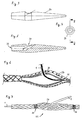
- a Aufsp Dr.Svik is arranged with rounded outer contour within the rope at a Jardinaus enclosuresstelle the rope, which has a central suitssöfnung, from which an outwardly opening execution opening goes off, wherein the at least one electrical conductor through the passage opening into the expansion body and out through the execution opening out of this and through the spread ropes to the outside.
- This measure ensures a lead out of the conductor from the rope at any point, without the risk of crushing or shearing of the conductor is when the rope is subjected to a tensile load.
- the expansion body has an at least partially hollow, spindle-shaped cross section in a longitudinal section plane containing a longitudinal axis of the rope. It is preferably provided that the execution opening is directed obliquely axially-radially outward. In addition, a protective sleeve can be arranged in the execution opening.
- the expansion body is secured positionally in the cable.
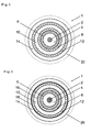
- Fig. 1 shows in a cross-sectional view of the structure of a cable 1 for coaxial arrangement within a merely indicated, braided plastic rope 20, which is to stretch thermally together with the cable received therein.
- An insulating cylindrical core of the cable 1 comprises a support element 2 consisting of a PA monofilament having a diameter of about 0.5 mm, on which a hard core layer 4 of PP having an outer diameter of about 1.6 mm is extruded.
- an insulating, compressible, compressible leveling layer 6 which in the illustrated example may have an outer diameter of about 2.2 mm +/- 0.1 mm and may consist of foamed LD-PE.
- the leveling layer may be made of a thermoplastic elastomer, such as PE, PP, PVC, or the like combined with non-thermoplastic portions, such as butadiene components.
- crosslinked plastic materials e.g. PETE materials, used to achieve high heat resistance, as well as fluorine polymers.
- a (first) conductor 8 is arranged, which has an outer diameter of about 2.8 mm and may be formed as a braid.
- the slope of the first conductor is 8 mm, which corresponds to a braid angle of 45 °.
- the optimal coverage is 80%.
- the first conductor 8 is concentrically surrounding this enclosing, insulating (first) sheath layer 10 having an outer diameter of about 3.6 mm, which is extruded in particular as a tube.
- the first cladding layer 10 may be made of a thermoplastic or of a thermoplastic elastomer.
- a second (further) conductor 12 is arranged concentrically on the first cladding layer 10 and, like the first conductor 8, preferably consists of a braid, which may have an outer diameter of 4.25 mm.
- the slope is preferably 10 mm and corresponds to a surface angle of 40 °. The optimal coverage is 65%.
- Both the first conductor and the second conductor may instead of a braid in the form of a swirl screen, without crossovers, be formed, which also provides in the case of an elongation of the rope the possibility that the conductor can be stretched in the longitudinal direction, while its diameter accordingly reduced.
- a second (further) jacket 14 is arranged concentrically around the second conductor 12 and preferably extruded as a tube made of plastic.
- the outer diameter of the second shell 14 may be about 5.0 mm +/- 0.1 mm.
- the second jacket 14 preferably consists of a high-temperature plastic, for example a thermoplastic or a thermoplastic elastomer.
- a (first) protective film 16 is arranged concentrically around the first conductor 8 and thus between this and the first jacket layer 10.
- the first protective film 16 is made of a durable plastic, in particular of PTFE with a thickness of about 0.05 mm, and may be extruded or, if made of a non-extrudable material, wound or banded.
- a second (further) protective film 18 is arranged around the second conductor 12, which is thus located between the latter and the second jacket layer 14.
- this protective film consists of a mechanically and high temperature resistant plastic, preferably made of PTFE, wherein it may have a thickness of about 0.05 mm.
- the second cladding layer 14 may have a slightly larger outer diameter of, for example, 5.1 mm +/- 0.1 mm in such an embodiment.
- the protective films serve as a security in the event that the insulation capacity of the first cladding layer 10 and / or the second cladding layer 14 is impaired by the subsequent thermal / mechanical stretching operation of the rope.
- a chemical fiber rope 20 (not to scale in the drawing in diameter), for example in the form of a 12-braid with twelve strands (or about 16, 20, 24, 32 strands), each of which, for example, three Strands turned could be.
- the structure and thickness of the rope depend on the expected mechanical requirements (tensile load, torsional and bending stress).
- the rope After completion of the braided plastic rope 20 with the cable 1 received therein both components, the rope together with the cable received therein, thermally stretched together.
- the rope is subjected at a temperature of about 90 ° C to 120 ° C a stretching force of about 30% of the tensile strength of the rope.
- the macromolecules of the man-made fiber material constituting the tow for example highly modular polyethylene (eg of the brand "Dyneema"), or aramid HMPA or HMPES, are oriented more extensively in the longitudinal direction than before the breaking strength of the rope is increased again and also the elongation under tensile stress is reduced.
- the rope can be stretched by 1% to 30% of its original length during this stretching process, for example by 10% of its original length.
- the cable is subject to longitudinal stretching, which may be particularly critical to the metallic components of the conductors. Due to the described design of the conductor with expansion reserve (mesh, spiraling, swirl screen or similar), this strain can also be compensated.
- the diameter of the core including the leveling layer (layers 2, 4 and 6) is the same as that described above Embodiments about 2.2 mm, resulting in assuming a constant volume (approximately, neglecting local compression of the compensation layer) at 10% elongation results in a reduced diameter of about 2.10 mm, which corresponds to a reduction of 0.10 mm. All off-core components are also subject to a diameter reduction of about 0.1 mm.
- the compensation layer consists of about 35% compressible volume (bubbles) and about 65% of a solid component.
- Fig. 3 to 7 explain a convenient solution to the problem, a centrally running in the cable conductor or the cable through the cable networks without risk of damage to the outside.
- a rigid Aufsp Dr. 24 is arranged with a rounded outer contour within the rope.
- the expansion body has a central passage opening 26, which extends at least from one end of the Aufsp Dahl stressess in this.
- the spreading body is hollow overall. From the passage opening 26, an outwardly opening execution opening 28 is in a substantially radial direction, the cable 1 first through the passage opening 26 into the Aufsp Schwarzmaschine 24 and from there through the execution opening 28 from the Aufsp Schwarz emotions out and through the spread rope through led to the outside.
- the expansion body ensures that the cable locally has a much larger diameter than usual, so that the individual interwoven strands and their crossover points get an increased mutual distance, which allows the passage of the cable.
- FIG. 3 to 5 shows another embodiment of a Trosp Dreck stressess 24, which is formed substantially spindle-shaped with a passage opening 26 and an execution opening 28.
- the cable can be protected in the region of the execution opening and the adjacent rope strands by a protective sleeve, which may be partially received in the execution opening.
- the spreading can be secured, for example, by Abitatien 30 ("Taklings").
Abstract
Description
Die Erfindung betrifft ein geflochtenes Kunststoff- bzw. Chemiefaser-Zugseil, das um mindestens einen elektrischen Leiter herum angeordnet ist, sowie ein Verfahren zum Herstellen eines derartigen Seils.The invention relates to a braided plastic fiber rope arranged around at least one electrical conductor and to a method for producing such a cable.
An ein Zugseil mit mindestens einem integriertem Elektrokabel, beispielsweise zur Datenübertragung oder Stromversorgung, werden häufig erhebliche Anforderungen im Hinblick auf die mechanischen, chemischen und elektrischen Eigenschaften gestellt, wie minimales Gewicht, maximale Bruchkraft, minimale Torsionsanfälligkeit, minimale Dehnung, Schwimmfähigkeit, Festigkeit gegen Biegewechsellasten, mindestens zweiadrige elektrische Verbindung für Datenübertragung und Stromversorgung und weitere.To a pull rope with at least one integrated electric cable, for example for data transmission or power supply, considerable requirements in terms of mechanical, chemical and electrical properties are often required, such as minimum weight, maximum breaking strength, minimum torsional susceptibility, minimal elongation, buoyancy, resistance to bending load, at least two-core electrical connection for data transmission and power supply and others.
Wesentliche Probleme bestehen darin, daß ein geflochtenes Seil auf einen mittig koaxial angeordneten Leiter bei Zugbelastung erhebliche Kompressionskräfte ausübt, und daß ein elektrischer Leiter bei im Betrieb auftretenden Dehnungen des lasttragenden Seils der Gefahr des Reißens ausgesetzt ist.Significant problems are that a braided cable exerts considerable compressive forces on a centrally coaxial conductor when subjected to tensile stress, and that an electrical conductor is exposed to the risk of tearing when the load-carrying cable is subjected to expansion during operation.
Aus der
Die Aufgabe der Erfindung besteht darin, ein geflochtenes Chemiefaser-Zugseil zu schaffen, das um mindestens einen elektrischen, Leiter herum angeordnet ist, bei dem die genannten Nachteile nicht mehr bestehen, so daß der Leiter sowohl gegen die Auswirkungen der Dehnung als auch der Druckbeanspruchung des Seils geschützt ist.The object of the invention is to provide a braided synthetic fiber rope, which is arranged around at least one electrical conductor around, in which the said disadvantages no longer exist, so that the conductor both against the effects of elongation and the compressive stress of the Rope is protected.
Erfindungsgemäß wird diese Aufgabe bei einem geflochtenen Chemiefaser-Zugseil, das um mindestens einen elektrischen Leiter herum angeordnet ist, durch die Maßnahme gelöst, daß das Chemiefaser-Zugseil zusammen mit dem darin aufgenommenen Leiter thermisch gereckt ist.According to the invention, this object is achieved in a braided synthetic fiber rope, which is arranged around at least one electrical conductor around , by the measure that the synthetic fiber tension cable is thermally stretched together with the recorded therein conductor.
Versuche haben gezeigt, daß aufgrund der besonderen Beanspruchungssituation während des thermischen Reckens eine mit einer permanenten Verformung des Seils und ggf. auch des Leiters einhergehende innige formschlüssige Verbindung der beiden Elemente eintritt, d.h. das Seil passt sich an die Außenkontur des Leiters an, der gleichzeitig durch die auftretenden nach innen gerichteten Kompressionskräfte zusammengedrückt wird, so daß bei einer anschließenden betrieblichen Zugbelastung des Seils die Gefahr einer Beeinträchtigung des Leiters durch die von außen einwirkenden Druckkräfte als auch die Reißgefahr des Leiters deutlich gemindert oder sogar praktisch ganz eliminiert werden können.Experiments have shown that due to the particular stress situation during the thermal stretching occurs with a permanent deformation of the rope and possibly also the conductor associated intimate positive connection of the two elements, i. the cable adapts to the outer contour of the conductor, which is simultaneously compressed by the occurring inwardly directed compression forces, so that in a subsequent operational tensile load of the rope, the risk of deterioration of the conductor by the externally applied compressive forces and the risk of tearing the conductor can be significantly reduced or even practically eliminated completely.
Eine zweckmäßige Ausführungsform zeichnet sich dadurch aus, daß der Leiter um einen Kern herum geflochten oder gewendelt ist. Durch diese Maßnahme erhält der Leiter eine Dehnungsreserve, so daß praktische keine Reißgefahr mehr besteht.An expedient embodiment is characterized in that the conductor is braided or wound around a core. By this measure, the head receives a stretch reserve, so that there is practically no risk of tearing.
Es kann vorgesehen sein, daß in dem Chemiefaser-Zugseil ein Kabel aufgenommen ist, das einen isolierten zylindrischen Kern, eine den Kern umschließende, isolierende, zusammendrückbare Ausgleichsschicht, einen auf der Ausgleichsschicht angeordneten, geflochtenen oder gewendelten Leiter und eine den Leiter umschließende isolierende Mantelschicht aufweist. Durch die Anordnung einer zusammendrückbaren Ausgleichsschicht werden die Auswirkungen der Kompressionskräfte des Seils nochmals reduziert. Die Ausgleichsschicht kann nachgiebig oder elastisch zusammendrückbar sein, beispielsweise in Form einer Schaumschicht.It may be provided that a cable is accommodated in the synthetic fiber pulling cable, comprising an insulated cylindrical core, an insulating, compressible leveling layer surrounding the core, a braided or coiled conductor arranged on the leveling layer, and an insulating jacket layer surrounding the conductor , The arrangement of a compressible leveling layer further reduces the effects of the compressive forces of the rope. The leveling layer may be compliant or elastically compressible, for example in the form of a foam layer.
Weiter kann vorgesehen sein, daß auf der Mantelschicht ein weiterer geflochtener oder gewendelter Leiter angeordnet ist, der von einer weiteren isolierenden Mantelschicht umschlossen ist. Der so gebildete elektrisch zweiadrige Aufbau bietet Vorteile für Datenübertragung und Stromversorgung.It can further be provided that a further braided or coiled conductor is arranged on the cladding layer, which is surrounded by a further insulating cladding layer. The thus formed two-wire electrical structure offers advantages for data transmission and power supply.
Zwischen dem Leiter und der Mantelschicht kann eine Schutzfolie aus Kunststoff angeordnet sein, insbesondere aus PTFE bestehend, sowie ggf. in entsprechender Weise eine weitere Schutzfolie zwischen dem weiteren Leiter und der weiteren Mantelschicht. Diese Folien dienen als Sicherheit, falls das Isolationsvermögen eines der Mäntel durch den Reckvorgang beeinträchtigt wird.Between the conductor and the cladding layer, a protective film made of plastic may be arranged, in particular made of PTFE, and optionally in a corresponding manner, a further protective film between the further conductor and the further cladding layer. These films serve as a security, if the insulation capacity of one of the coats is affected by the stretching process.
Die Ausgleichsschicht kann aus geschäumtem oder ungeschäumten Kunststoff, wie etwa einem thermoplastischen Elastomer oder einer Kombination aus einem Elastomer und einem Thermoplasten (Zwei-Phasen-System), bestehen.The leveling layer may be made of foamed or unfoamed plastic, such as a thermoplastic elastomer or a combination of an elastomer and a thermoplastic (two-phase system).
Es kann vorgesehen sein, daß mindestens eine Mantelschicht aus einem extrudierten Kunststoff, insbesondere einem Thermoplasten oder einem thermoplastischen Elastomer, besteht. Zweckmäßigerweise ist vorgesehen, daß der Kern ein Trägerelement in Form eines Monofils und eine darauf extrudierte Kernschicht aufweist.It can be provided that at least one jacket layer consists of an extruded plastic, in particular a thermoplastic or a thermoplastic elastomer. Appropriately, it is provided that the core has a carrier element in the form of a monofilament and an extruded core layer.
Das den mindestens einen Leiter enthaltende Chemiefaser-Zugseil kann bei einer Temperatur zwischen 60° C und 200° C, insbesondere bei 90° C bis 130° C, gereckt sein.The synthetic fiber traction rope containing the at least one conductor can be stretched at a temperature between 60 ° C and 200 ° C, in particular at 90 ° C to 130 ° C.
Dabei ist es zweckmäßig, daß das Chemiefaser-Zugseil einer Reckkraft unterworfen ist, die zwischen 1 % und 50% und insbesondere 20% bis 30% der Zugfestigkeit des Chemiefaser-Zugseils beträgt. Das Chemiefaser-Zugseil kann zusammen mit dem darin aufgenommenen Leiter oder Kabel einem Reckverhältnis von 3%, 5%, 7%, 9%, 10%, 15% oder mehr unterworfen werden, wobei das Reckverhältnis die Längenzunahme des gereckten Chemiefaser-Zugseils, bezogen auf die Ausgangslänge, bedeutet.It is expedient that the synthetic fiber tension rope is subjected to a stretching force which is between 1% and 50% and in particular 20% to 30% of the tensile strength of the synthetic fiber rope. The manmade tow may be subjected to a draw ratio of 3%, 5%, 7%, 9%, 10%, 15% or more together with the conductor or cable received therein, the draw ratio being the increase in length of the drawn tow rope to the initial length, means.
Die Aufgabe der Erfindung wird ferner gelöst durch ein Verfahren zum Herstellen eines geflochtenen Chemiefaser-Zugseils mit einem darin aufgenommenen elektrischen Leiter, mit den Schritten: a) Bereitstellen des elektrischen Leiters, b) Flechten des Chemiefaser-Zugseils um den Leiter herum, und c) thermisches Recken des den Leiter enthaltenden Chemiefaser-Zugseils.The object of the invention is further achieved by a method for producing a braided synthetic fiber rope with an electrical conductor received therein, comprising the steps of: a) providing the electrical conductor, b) braiding the synthetic fiber rope around the conductor, and c) thermal stretching of the synthetic fiber pull rope containing the conductor.
Schritt a) kann folgende Schritte umfassen: a1) Bereitstellen eines isolierenden Kerns, a2) Extrudieren einer den Kern umschließenden, zusammendrückbaren Ausgleichsschicht um den Kern herum, a3) Anordnen eines geflochtenen oder gewendelten elektrischen Leiters auf der Ausgleichsschicht, a4) Extrudieren einer den Leiter umschließenden isolierenden Mantelschicht um den Leiter herum, insbesondere bestehend aus einem thermoplastischen Elastomer.Step a) may comprise the steps of: a1) providing an insulating core, a2) extruding a compressive layer surrounding the core around the core, a3) placing a braided or coiled electrical conductor on the leveling layer, a4) extruding a conductor surrounding the conductor insulating jacket layer around the conductor, in particular consisting of a thermoplastic elastomer.
Schritt b) beinhaltet ein geflochtenes (z.B. Rundgeflecht) Chemiefaser-Zugseil, das ggf. mit einem schützenden Mantel überflochten und/oder beschichtet sein kann und 3, 4, 6, 8, 12, 16, 20, 24, 32 oder 48 Litzen umfassen kann.Step b) includes a braided (eg, braided) synthetic fiber pull rope which may optionally be braided and / or coated with a protective sheath and comprise 3, 4, 6, 8, 12, 16, 20, 24, 32, or 48 strands can.
Bevorzugt ist vorgesehen, daß das Chemiefaser-Zugseil bei einer Temperatur zwischen 60° C und 200° C, insbesondere 90° C bis 130° C, gereckt wird. Bevorzugt wird das Chemiefaser-Zugseil bei einem wie oben angegebenen Reckverhältnis geweckt.It is preferably provided that the synthetic fiber tension rope at a temperature between 60 ° C and 200 ° C, in particular 90 ° C to 130 ° C, is stretched. The synthetic fiber tensioning cable is preferably awakened at a stretching ratio as indicated above.
In Weiterbildung der Erfindung kann vorgesehen sein, daß beim Schritt a) folgende Schritte durchgeführt werden:-) Anordnen eines weiteren geflochtenen oder gewendelten Leiters auf der Mantelschicht, und -) Extrudieren einer den weiteren Leiter umschließenden, isolierenden, weiteren Mantelschicht um den weiteren Leiter herum, insbesondere bestehend aus einem thermoplastischen Elastomer.In a further development of the invention, it can be provided that the following steps are carried out in step a) :-) arranging a further braided or coiled conductor on the jacket layer, and extruding a further insulating layer surrounding the further conductor around the further conductor , in particular consisting of a thermoplastic elastomer.
Zwischen dem Leiter und der Mantelschicht kann eine Schutzfolie aus Kunststoff, insbesondere aus PTFE, angeordnet werden, insbesondere durch Bandieren bzw. Umwickeln.Between the conductor and the cladding layer, a protective film made of plastic, in particular of PTFE, can be arranged, in particular by banding or wrapping.
In entsprechender Weise kann vorgesehen sein, daß zwischen dem weiteren Leiter und der weiteren Mantelschicht eine weitere Schutzfolie angeordnet wird. Der Kern kann durch Extrudieren einer Kernschicht auf ein zylindrisches Trägerelement hergestellt werden.In a corresponding manner it can be provided that a further protective film is arranged between the further conductor and the further jacket layer. The core can be made by extruding a core layer onto a cylindrical support member.
Bevorzugt ist vorgesehen, daß die Ausgleichsschicht aus geschäumtem oder aufschäumbarem Kunststoff extrudiert wird.It is preferably provided that the leveling layer of foamed or foamable plastic is extruded.
Die Erfindung sieht bevorzugt vor, daß das Chemiefaser-Zugseil bei einer Reckkraft gereckt wird, die zwischen 1% und 50% und insbesondere 20% bis 30% der Zugfestigkeit des Chemiefaser-Zugseils beträgt.The invention preferably provides that the man-made tow rope is stretched at a stretching force of between 1% and 50% and in particular 20% to 30% of the tensile strength of the manmade tow rope.
Der Leiter kann geflochten sein und einen Flechtwinkel von 35° bis 55°, insbesondere 45° aufweisen.The conductor may be braided and have a braid angle of 35 ° to 55 °, in particular 45 °.
Der Leiter kann eine Bedeckung von 70% bis 90%, insbesondere 80% aufweisen.The conductor may have a coverage of 70% to 90%, in particular 80%.
Es kann vorgesehen sein, daß der weitere Leiter geflochten ist und einen Flechtwinkel von 30° bis 50°, insbesondere 40° aufweist.It can be provided that the further conductor is braided and has a braid angle of 30 ° to 50 °, in particular 40 °.
Der weitere Leiter kann eine Bedeckung von 50% bis 80%, insbesondere 65% aufweisen.The further conductor can have a coverage of 50% to 80%, in particular 65%.
In bevorzugter Weiterbildung der Erfindung kann vorgesehen sein, daß an einer Kabelausführungsstelle des Seils ein Aufspreizkörper mit abgerundeter Außenkontur innerhalb des Seils angeordnet ist, der eine zentrale Durchführungsöfnung aufweist, von der eine nach außen mündende Ausführungsöffnung abgeht, wobei der mindestens eine elektrische Leiter durch die Durchführungsöffnung in den Aufspreizkörper hinein und durch die Ausführungsöffnung aus diesem heraus und durch das aufgespreizte Seile hindurch nach außen geführt ist. Diese Maßnahme gewährleistet eine Herausführung des Leiters aus dem Seil an einer beliebigen Stelle, ohne daß die Gefahr einer Quetschung oder Abscherung des Leiters besteht, wenn das Seil einer Zugbelastung ausgesetzt wird.In a preferred embodiment of the invention can be provided that a Aufspreizkörper is arranged with rounded outer contour within the rope at a Kabelausführungsstelle the rope, which has a central Durchführungsöfnung, from which an outwardly opening execution opening goes off, wherein the at least one electrical conductor through the passage opening into the expansion body and out through the execution opening out of this and through the spread ropes to the outside. This measure ensures a lead out of the conductor from the rope at any point, without the risk of crushing or shearing of the conductor is when the rope is subjected to a tensile load.
Hierbei kann vorgesehen sein, daß der Aufspreizkörper in einer eine Längsachse des Seils enthaltenden Längsschnittebene einen wenigstens teilweise hohlen, spindelförmigen Querschnitt aufweist. Bevorzugt ist vorgesehen, daß die Ausführungsöffnung schräg axial-radial nach außen gerichtet ist. Außerdem kann in der Ausführungsöffnung eine Schutzhülse angeordnet sein.It can be provided that the expansion body has an at least partially hollow, spindle-shaped cross section in a longitudinal section plane containing a longitudinal axis of the rope. It is preferably provided that the execution opening is directed obliquely axially-radially outward. In addition, a protective sleeve can be arranged in the execution opening.
Zweckmäßigerweise ist der Aufspreizkörper in dem Seil positionsmäßig gesichert.Conveniently, the expansion body is secured positionally in the cable.
Weitere Vorteile und Merkmale der Erfindung werden anhand der nachfolgenden Beschreibung von Ausführungsbeispielen deutlich, wobei auf eine Zeichnung Bezug genommen ist, in der
-
Fig. 1 eine erste Ausführungsform eines Kabels zur Aufnahme in einem geflochtenen Kunststoffseil zeigt, -
Fig. 2 eine Querschnittsansicht einer zweiten Ausführungsform ähnlichFig. 1 zeigt, und -
Fig. 3 und 4 eine Kabelein- bzw. -ausführung mit einem abgerundeteten starren Aufspreizkörper zeigen.
-
Fig. 1 shows a first embodiment of a cable for receiving in a braided plastic rope, -
Fig. 2 a cross-sectional view of a second embodiment similarFig. 1 shows, and -
3 and 4 show a Kabelein- or -ausführung with a rounded rigid Aufspreizkörper.
Ein isolierender zylindrischer Kern des Kabels 1 weist ein Trägerelement 2, bestehend aus einem PA-Monofil mit einem Durchmesser von etwa 0,5 mm auf, auf das eine harte Kernschicht 4 aus PP mit einem äußeren Durchmesser von etwa 1,6 mm extrudiert ist.An insulating cylindrical core of the
Um den so gebildeten Kern herum ist eine isolierende, nachgiebig zusammendrückbare Ausgleichsschicht 6 extrudiert, die in dem darstellten Beispiel einen Außendurchmesser von etwa 2,2 mm +/- 0,1 mm aufweisen kann und aus geschäumtem LD-PE bestehen kann. Alternativ kann die Ausgleichsschicht aus einem thermoplastischen Elastomer bestehen, wie beispielsweise PE, PP, PVC o.ä., das mit nicht thermoplastischen Anteilen, etwa Butadienbestandteilen, kombiniert ist. Auch können (etwa mit Betastrahlung) vernetzte Kunststoffmaterialien, z.B. PETE-Materialien, verwendet werden, um eine hohe Wärmeformbeständigkeit zu erreichen, sowie Fluor-Polymere.Around the core thus formed is extruded an insulating, compressible,
Koaxial um die Ausgleichsschicht und den darin befindlichen Kern herum ist ein (erster) Leiter 8 angeordnet, der einen Außendurchmesser von etwa 2,8 mm aufweisen und als Geflecht ausgebildet sein kann. Beispielsweise können 6 x 7 Einzellitzen aus verzinktem Kupfer mit einer einzelnen Querschnittsfläche von 0,15 mm vorgesehen sein, was einen Gesamtquerschnitt von 42 x 0,15 mm2 = 0,75 mm2 ergibt.Coaxially around the leveling layer and the core located therein, a (first)
Bevorzugt liegt die Steigung des ersten Leiters bei 8 mm, was einem Flechtwinkel von 45° entspricht. Die optimale Bedeckung beträgt 80%.Preferably, the slope of the first conductor is 8 mm, which corresponds to a braid angle of 45 °. The optimal coverage is 80%.
Um den ersten Leiter 8 herum ist konzentrisch eine diesen umschließende, isolierende (erste) Mantelschicht 10 mit einem Außendurchmesser von etwa 3,6 mm angeordnet, die insbesondere als Schlauch extrudiert ist. Die erste Mantelschicht 10 kann aus einem thermoplastischen Kunststoff oder aus einem thermoplastischen Elastomer bestehen.To the
Ein zweiter (weiterer) Leiter 12 ist konzentrisch auf der ersten Mantelschicht 10 angeordnet und besteht, ebenso wie der erste Leiter 8, bevorzugt aus einem Geflecht, das einen Außendurchmesser von 4,25 mm aufweisen kann. Der zweite Leiter 12 besteht bevorzugt aus 6 x 7 Einzellitzen aus verzinktem Kupfer mit einem Einzelquerschnitt von 0,15 mm, wodurch eine gesamte Querschnittsfläche von 42 x 0,15 mm2 = 0,75 mm2 gebildet ist. Die Steigung beträgt bevorzugt 10 mm und entspricht einem Flächenwinkel von 40°. Die optimale Bedeckung beträgt 65%.A second (further)
Sowohl der erste Leiter als auch der zweite Leiter kann anstelle eines Geflechts in Form eines Drallschirms, also ohne Überkreuzungen, ausgebildet sein, der ebenfalls im Falle einer Dehnung des Seils die Möglichkeit bietet, daß der Leiter in Längsrichtung gestreckt werden kann und dabei seinen Durchmesser entsprechend reduziert.Both the first conductor and the second conductor may instead of a braid in the form of a swirl screen, without crossovers, be formed, which also provides in the case of an elongation of the rope the possibility that the conductor can be stretched in the longitudinal direction, while its diameter accordingly reduced.
Ein zweiter (weiterer) Mantel 14 ist konzentrisch um den zweiten Leiter 12 herum angeordnet und bevorzugt als Schlauch aus Kunststoff extrudiert. Der Außendurchmesser des zweiten Mantels 14 kann etwa 5,0 mm +/- 0,1 mm betragen. Ebenso wie der erste Mantel 10 besteht der zweite Mantel 14 bevorzugt aus einem Hochtemperatur-Kunststoff, beispielsweise aus einem thermoplastischen Kunststoff oder einem thermoplastischen Elastomer.A second (further)
Bei der Ausführungsform nach
Weiterhin ist vorgesehen, daß auch um den zweiten Leiter 12 herum eine zweite (weitere) Schutzfolie 18 angeordnet ist, die sich somit zwischen diesem und der zweiten Mantelschicht 14 befindet. Auch diese Schutzfolie besteht aus einem mechanisch und gegen hohe Temperaturen widerstandsfähigen Kunststoff, bevorzugt aus PTFE, wobei sie eine Dicke von etwa 0,05 mm aufweisen kann.
Die zweite Mantelschicht 14 kann bei einer solchen Ausführung einen etwas größeren Außendurchmesser von beispielsweise 5,1 mm +/- 0,1 mm aufweisen.Furthermore, it is provided that a second (further)
The
Die Schutzfolien dienen als Sicherheit für den Fall, daß das Isolationsvermögen der ersten Mantelschicht 10 und/oder der zweiten Mantelschicht 14 durch den anschließenden thermisch/mechanischen Reckvorgang des Seils beeinträchtigt wird.The protective films serve as a security in the event that the insulation capacity of the
Koaxial um das Kabel 1 wird ein Chemiefaserseil 20 geflochten (in der Zeichnung nicht maßstäblich im Durchmesser), beispielsweise in Form eines 12er-Geflechts mit zwölf Litzen (oder etwa mit 16, 20, 24, 32 Litzen), wobei diese jeweils beispielsweise aus drei Strängen gedreht sein können. Aufbau und Dicke des Seils richten sich nach den zu erwartenden mechanischen Anforderungen (Zugbelastung, Torsions- und Biegebeanspruchung).Coaxially around the
Nach Fertigstellung des geflochtenen Kunststoffseils 20 mit dem darin aufgenommenen Kabel 1 werden beide Komponenten, das Seil zusammen mit dem darin aufgenommenen Kabel, gemeinsam thermisch gereckt. Das Seil wird dabei bei einer Temperatur von etwa 90° C bis 120° C einer Reckkraft von etwa 30% der Zugfestigkeit des Seils unterworfen. Bei diesem Vorgang werden die Makromoleküle des Chemiefasermaterials, aus dem das Seil besteht, beispielsweise hochmodulares Polyethylen (z.B. der Marke "Dyneema"), oder etwa Aramid HMPA oder ein HMPES, in stärkerem Maße in Längsrichtung ausgerichtet als dies vorher der Fall war, so daß die Bruchkraft des Seils nochmals gesteigert wird und auch die Dehnung bei Zugbeanspruchung reduziert wird.After completion of the braided
Das Seil kann bei diesem Reckvorgang um 1% bis 30% seiner Ursprungslänge bleibend gedehnt werden, beispielsweise um 10% seiner ursprünglichen Länge.The rope can be stretched by 1% to 30% of its original length during this stretching process, for example by 10% of its original length.
Da sich das schlauchförmig geflochtene Seil während des Reckvorgangs radial zusammenzieht, wird eine starke kompressive Druckkraft auf das Kabel ausgeübt, deren Auswirkungen auf den/die Leiter weitestgehend durch die Ausgleichsschicht 6 aufgenommen und kompensiert werden. Es werden nämlich die mehr oder weniger unkontrolliert und ungleichmäßig auftretenden Kräfte durch die Komprimierbarkeit der Ausgleichsschicht kompensiert. Überkreuzungsstellen des Leitergeflechts, die eine vergrößerte Dicke in radialer Richtung aufweisen, werden lokal in die Ausgleichschicht gedrückt und bleiben so unverletzt. Lokale Druckspitzen, die von der Geflechtstruktur der Leiter und den Strängen des Seils herrühren, werden verteilt und ausgeglichen.As the tubular braided rope contracts radially during the stretching operation, a strong compressive compressive force is exerted on the cable, the effects of which on the conductor (s) being largely absorbed and compensated by the
Darüber hinaus wird das Kabel, ebenso wie das Seil selbst, einer Dehnung in Längsrichtung unterworfen, die insbesondere für die metallischen Komponenten der Leiter kritisch sein kann. Aufgrund der beschriebenen Ausbildung der Leiter mit Dehnungsreserve (Geflecht, Wendelung, Drallschirm o.ä.) kann diese Dehnung ebenfalls kompensiert werden.Moreover, as well as the rope itself, the cable is subject to longitudinal stretching, which may be particularly critical to the metallic components of the conductors. Due to the described design of the conductor with expansion reserve (mesh, spiraling, swirl screen or similar), this strain can also be compensated.
Als Beispiel sei eine Durchmesserreduzierung des Kabels bei einer Längsdehnung von 10%, bezogen auf die ursprüngliche ungedehnte Länge, betrachtet. Der Durchmesser des Kerns einschließlich Ausgleichsschicht (Schichten 2, 4 und 6) beträgt bei den vorstehend beschriebenen Ausführungsbeispielen etwa 2,2 mm, woraus sich unter Annahme konstanten Volumens (näherungsweise, bei Vernachlässigung lokaler Kompression der Ausgleichsschicht) bei 10% Dehnung ein reduzierter Durchmesser von etwa 2,10 mm ergibt, was einer Reduzierung um 0,10 mm entspricht. Alle außerhalb des Kerns liegenden Komponenten sind ebenfalls einer Reduzierung des Durchmessers um etwa 0,1 mm unterworfen. Als Beispiel besteht die Ausgleichsschicht zu ca. 35% aus komprimierbarem Volumen (Blasen) und zu ca. 65% aus einer festen Komponente.As an example, consider a reduction in diameter of the cable at a 10% elongation, based on the original unstretched length. The diameter of the core, including the leveling layer (
Bei einer Ausbildung der Leiter 8, 12 als Geflecht, wie beschrieben, mit einem Flechtwinkel von 45° ändert sich die Bedeckung etwa 80,8% aufgrund der Durchmesserreduzierung des Kerns bei gleichzeitiger Vergrößerung der Steigung des Geflechts auf etwa 81%, was vernachlässigbar ist. Auch bei dem zweiten Leiter 12 ändert sich die Geflechtbedeckung lediglich um 1%.When the
Auch bei einer Zugbelastung des Seils ändert sich hieran nichts, d.h. das Kabel ist nicht der Gefahr einer Beschädigung durch Abquetschen o.ä. durch benachbarte Seillitzen ausgesetzt.
Sofern zweckmäßig, kann das Kabel im Bereich der Ausführungsöffnung und der benachbarten Seillitzen durch eine Schutzhülse geschützt werden, die teilweise in der Ausführungsöffnung aufgenommen sein kann.If appropriate, the cable can be protected in the region of the execution opening and the adjacent rope strands by a protective sleeve, which may be partially received in the execution opening.
Positionsmäßig kann der Aufspreizkörper beispielsweise durch Abbindungen 30 ("Taklings") gesichert werden.Positionally, the spreading can be secured, for example, by Abbindungen 30 ("Taklings").
- 11
- Kabelelectric wire
- 22
- Trägerelementsupport element
- 44
- harte Kernschichthard core layer
- 66
- Ausgleichsschichtleveling layer
- 88th
- erster Leiterfirst leader
- 1010
- erste Mantelschichtfirst cladding layer
- 1212
- zweiter Leitersecond conductor
- 1414
- zweite Mantelschichtsecond cladding layer
- 1616
- erste Schutzfoliefirst protective film
- 1818
- zweite Schutzfoliesecond protective film
- 2020
- geflochtenes Chemiefaserseilbraided synthetic fiber rope
- 2222
- KabelausführungsstelleCable design Point
- 2424
- AufspreizkörperAufspreizkörper
- 2626
- DurchführungsöffnungDuct opening
- 2828
- Ausführungsöffnungexit opening
Claims (15)
- Braided chemical fibre traction rope which is arranged around at least one electrical conductor (8, 12), characterised in that the chemical fibre traction rope together with the conductor (8, 12) contained therein is thermally stretched.
- Braided chemical fibre traction rope according to claim 1, characterised in that contained in the chemical fibre traction rope is a cable (1) which has an insulating cylindrical core (2, 4), an insulating compensating layer (6) that encloses the core (2, 4), a braided or coiled conductor (8) that is arranged on the compensating layer (6), and an insulating casing layer (10) that encloses the conductor (8).
- Braided chemical fibre traction rope according to claim 2, characterised in that arranged on the casing layer (10) is an additional braided or coiled conductor (12), which is enclosed by an additional insulating casing layer (14).
- Braided chemical fibre traction rope according to claim 3, characterised in that arranged between the conductor (8) and the casing layer (10) is a protective film (16) made of plastic, which in particular comprises PTFE.
- Braided chemical fibre traction rope according to one of the claims 3 or 4, characterised in that at least one casing layer comprises extruded plastic, in particular a thermoplastic or a thermoplastic elastomer.
- Braided chemical fibre traction rope according to one of the claims 3 to 5, characterised in that the core has a carrier element (2) in the form of a monofilament and a core layer (4) that is extruded onto it.
- Braided chemical fibre traction rope according to one of the preceding claims, characterised in that at a cable exit point (22), a splaying element (24) with a rounded-off outer contour is arranged within the chemical fibre traction rope, this [splaying element] having a central passage opening (26) leading out from which is an exit opening (28) that leads to the outside, wherein the at least one electrical conductor (1) is led through the passage opening (26) into the splaying element, and through the exit opening (28) out of the same, and through the splayed chemical fibre traction rope to the outside.
- Method for manufacturing a braided chemical fibre traction rope with a conductor contained within it, with the steps:a) providing the electrical conductor (1; 8, 12),b) braiding the chemical fibre traction rope (20) around the conductor,c) thermally stretching the chemical fibre traction rope that contains the conductor.
- Method according to claim 8, characterised in that step a) comprises the following steps:a1) providing an insulating core (2, 4),a2) extruding a compensating layer (6) which encloses the core (2, 4), around the core (2, 4), andwhich in particular can be elastically compressed,a3) arranging a braided or coiled electrical conductor (8, 12) on the compensating layer (6), a4) extruding an insulating casing layer (10) around the conductor, enclosing the conductor, in particular comprising a thermoplastic or a thermoplastic elastomer.
- Method according to claim 8 or 9, characterised in that the chemical fibre traction rope is stretched at a temperature between 60° C and 200° C, in particular 90° C to 130° C.
- Method according to one of the claims 9 or 10, if dependent on claim 9, characterised in that at step a), the following steps are carried out:- arranging an additional braided or coiled conductor (12) on the casing layer (10), and- extruding an additional insulating casing layer (14) around the additional conductor (12), enclosing the additional conductor (12), in particular comprising a thermoplastic or a thermoplastic elastomer.
- Method according to one of the claims 9, 10, if dependent on claim 9 or 11, characterised in that arranged between the conductor (8) and the casing layer (10) is a protective film (16) made of plastic, in particular PTFE.
- Method according to claim 11 or 12, characterised in that arranged between the additional conductor (12) and the additional casing layer (14) is an additional protective film (18) made of plastic, in particular PTFE.
- Method according to one of the claims 9 to 13, characterised in that the core (2, 4) is produced by extruding a core layer (4) onto a cylindrical carrier element (2).
- Method according to one of the claims 8 to 14, characterised in that the chemical fibre traction rope is stretched with a stretching force that is between 1% and 50%, and in particular 20% to 30%, of the tensile strength of the chemical fibre traction rope.
Applications Claiming Priority (2)
| Application Number | Priority Date | Filing Date | Title |
|---|---|---|---|
| DE102007050402A DE102007050402B3 (en) | 2007-10-19 | 2007-10-19 | Rope with electrical conductor received therein |
| PCT/DE2008/001713 WO2009049616A2 (en) | 2007-10-19 | 2008-10-20 | Cable with electrical conductor included therein |
Publications (2)
| Publication Number | Publication Date |
|---|---|
| EP2207924A2 EP2207924A2 (en) | 2010-07-21 |
| EP2207924B1 true EP2207924B1 (en) | 2013-12-18 |
Family
ID=40340589
Family Applications (1)
| Application Number | Title | Priority Date | Filing Date |
|---|---|---|---|
| EP08840299.5A Active EP2207924B1 (en) | 2007-10-19 | 2008-10-20 | Braided rope of synthetic fibers with electrical conductor included therein |
Country Status (7)
| Country | Link |
|---|---|
| US (1) | US9340924B2 (en) |
| EP (1) | EP2207924B1 (en) |
| CN (1) | CN101883885B (en) |
| DE (1) | DE102007050402B3 (en) |
| DK (1) | DK2207924T3 (en) |
| HK (1) | HK1146738A1 (en) |
| WO (1) | WO2009049616A2 (en) |
Families Citing this family (7)
| Publication number | Priority date | Publication date | Assignee | Title |
|---|---|---|---|---|
| CN102926247B (en) * | 2012-11-22 | 2016-01-20 | 江苏赛福天钢索股份有限公司 | A kind of crane plastic-filled steel wire rope |
| US20140273594A1 (en) * | 2013-03-14 | 2014-09-18 | Delphi Technologies, Inc. | Shielded cable assembly |
| EP3210269B1 (en) * | 2014-10-21 | 2020-08-19 | swiss inventix GmbH | Electric energy transmission tether for an airborne wind power station |
| CN106049139A (en) * | 2016-07-22 | 2016-10-26 | 贵州钢绳股份有限公司 | Plastic filled steel wire rope for electric shovel and manufacture method for the same |
| WO2021075648A1 (en) * | 2019-10-18 | 2021-04-22 | 한국과학기술원 | Fiber-type strain sensor having core-shell structure, and manufacturing method therefor |
| FR3107286B1 (en) * | 2020-02-13 | 2022-04-01 | Univ Reims Champagne Ardenne | Method for detecting the modification of the environment of a cable |
| CN117133507B (en) * | 2023-10-25 | 2024-01-02 | 锐洋集团东北电缆有限公司 | Overhead insulated cable and production equipment thereof |
Family Cites Families (40)
| Publication number | Priority date | Publication date | Assignee | Title |
|---|---|---|---|---|
| US3126442A (en) * | 1964-03-24 | Extensible electric cable | ||
| DE286317C (en) * | ||||
| US2047152A (en) * | 1932-10-22 | 1936-07-07 | Galvin Mfg Corp | Automobile radio cable |
| US2235523A (en) * | 1938-11-12 | 1941-03-18 | Gen Electric | Electric cord |
| US2456015A (en) * | 1944-08-01 | 1948-12-14 | Columbian Rope Co | Electrical conductor |
| GB784808A (en) * | 1955-01-25 | 1957-10-16 | Redler Conveyors Ltd | Improvements in or relating to rope incorporating an insulated electrical conductor |
| US3153696A (en) | 1956-03-12 | 1964-10-20 | Schlumberger Well Surv Corp | Methods for processing cables |
| US2940883A (en) * | 1956-05-01 | 1960-06-14 | United States Steel Corp | Apparatus for hot prestressing armored cable |
| DE1132204B (en) * | 1960-01-26 | 1962-06-28 | Draht Isolierwerk Heermann | Flexible electrical cable for the control of missiles, e.g. E.g. missiles or toy planes |
| US3530661A (en) * | 1969-03-21 | 1970-09-29 | Schlumberger Technology Corp | Method for prestressing armored cable |
| US3823253A (en) * | 1970-07-10 | 1974-07-09 | Belden Corp | Stretchable cable |
| US3932697A (en) * | 1974-07-29 | 1976-01-13 | Wall Industries, Inc. | Rope terminations and methods and apparatus for fabricating the same |
| US4084065A (en) * | 1976-12-02 | 1978-04-11 | The United States Of America As Represented By The Secretary Of The Navy | Antistrumming cable |
| IT1093219B (en) * | 1978-03-10 | 1985-07-19 | Sciocco Angelo | DEVICE FOR LOCKING CABLES, ROPES AND SIMILAR SUBJECT TO TRACTION |
| FR2509512A1 (en) * | 1981-07-10 | 1983-01-14 | Chavanoz Ind | REMOTE CONTROL CABLE |
| DE3228297A1 (en) | 1982-07-29 | 1983-03-24 | Leopold F. 7000 Stuttgart Schmid | Friction clutch, in particular for motor vehicles |
| JPS60119013A (en) * | 1983-11-30 | 1985-06-26 | 丸一産業株式会社 | Signal transmitting strand |
| US4819914A (en) * | 1985-07-05 | 1989-04-11 | All Line, Inc. | Electrical fence for livestock |
| DE3625631A1 (en) * | 1986-07-29 | 1988-02-04 | Gore W L & Co Gmbh | ELECTROMAGNETIC SHIELDING |
| DE3906575A1 (en) * | 1989-03-02 | 1990-09-06 | Philips Patentverwaltung | ELECTRIC CABLE WITH A BRAID CORD SURROUNDING THE CABLE CORE |
| US4975543A (en) * | 1989-06-30 | 1990-12-04 | Sanders Associates, Inc. | Energy-absorbing towline with embedded electrical conductors and drogue deployment system including same |
| US5182779A (en) * | 1990-04-05 | 1993-01-26 | Ltv Aerospace And Defense Company | Device, system and process for detecting tensile loads on a rope having an optical fiber incorporated therein |
| US5166477A (en) * | 1991-05-28 | 1992-11-24 | General Electric Company | Cable and termination for high voltage and high frequency applications |
| DE9310993U1 (en) * | 1993-07-22 | 1994-11-17 | Gore W L & Ass Gmbh | Broadband radio frequency-compatible electrical coaxial cable |
| US6005191A (en) * | 1996-05-02 | 1999-12-21 | Parker-Hannifin Corporation | Heat-shrinkable jacket for EMI shielding |
| US5749214A (en) | 1996-10-04 | 1998-05-12 | Cook; Roger B. | Braided or twisted line |
| US6800809B2 (en) * | 1997-08-14 | 2004-10-05 | Commscope Properties, Llc | Coaxial cable and method of making same |
| FI973367A (en) * | 1997-08-15 | 1999-02-16 | Merinonita Oy | Method and apparatus for the treatment of problem waste |
| DE29808030U1 (en) * | 1998-05-05 | 1999-09-16 | Schrey Gerhard | Barrier rope with internal power or EDP cable for exhibitions, trade fairs and museums or to cordon off danger zones |
| EP0962945A1 (en) * | 1998-05-11 | 1999-12-08 | W.L. GORE & ASSOCIATES GmbH | Electrical signal line cable assembly |
| DE69939191D1 (en) * | 1998-10-06 | 2008-09-04 | Telefonix Inc | Retractable cable arrangement |
| US6631095B1 (en) * | 1999-07-08 | 2003-10-07 | Pgs Exploration (Us), Inc. | Seismic conductive rope lead-in cable |
| US20020189845A1 (en) * | 2001-06-14 | 2002-12-19 | Gorrell Brian E. | High voltage cable |
| TWI264020B (en) * | 2002-02-08 | 2006-10-11 | Hirakawa Hewtech Corp | Foamed coaxial cable with high precision and method of fabricating same |
| US6583360B1 (en) * | 2002-02-08 | 2003-06-24 | Igor Yudashkin | Coaxial audio cable assembly |
| AP1807A (en) * | 2002-04-23 | 2007-12-14 | Composite Tech Corporation | Aluminium conductor composite core reinforced cable and method of manufacture. |
| US6712620B1 (en) * | 2002-09-12 | 2004-03-30 | High Connection Density, Inc. | Coaxial elastomeric connector system |
| US7007350B1 (en) * | 2003-12-23 | 2006-03-07 | Franke Gary J | Spring-loaded compression cable grab |
| US7409815B2 (en) * | 2005-09-02 | 2008-08-12 | Gore Enterprise Holdings, Inc. | Wire rope incorporating fluoropolymer fiber |
| US8208777B2 (en) * | 2009-02-24 | 2012-06-26 | Intelliserv, Llc | Structure for electrical and/or optical cable using impregnated fiber strength layer |
-
2007
- 2007-10-19 DE DE102007050402A patent/DE102007050402B3/en not_active Expired - Fee Related
-
2008
- 2008-10-20 WO PCT/DE2008/001713 patent/WO2009049616A2/en active Application Filing
- 2008-10-20 EP EP08840299.5A patent/EP2207924B1/en active Active
- 2008-10-20 DK DK08840299.5T patent/DK2207924T3/en active
- 2008-10-20 CN CN2008801191066A patent/CN101883885B/en not_active Expired - Fee Related
- 2008-10-20 US US12/738,790 patent/US9340924B2/en active Active
-
2011
- 2011-01-27 HK HK11100843.6A patent/HK1146738A1/en not_active IP Right Cessation
Also Published As
| Publication number | Publication date |
|---|---|
| US20110132660A1 (en) | 2011-06-09 |
| CN101883885A (en) | 2010-11-10 |
| WO2009049616A3 (en) | 2009-07-02 |
| CN101883885B (en) | 2012-10-03 |
| HK1146738A1 (en) | 2011-07-08 |
| DK2207924T3 (en) | 2014-03-24 |
| WO2009049616A2 (en) | 2009-04-23 |
| DE102007050402B3 (en) | 2009-06-04 |
| US9340924B2 (en) | 2016-05-17 |
| EP2207924A2 (en) | 2010-07-21 |
| WO2009049616A8 (en) | 2010-05-27 |
Similar Documents
| Publication | Publication Date | Title |
|---|---|---|
| EP2207924B1 (en) | Braided rope of synthetic fibers with electrical conductor included therein | |
| DE3318233C2 (en) | Optical cable element or cable and method for its manufacture | |
| DE3513859C2 (en) | Underwater communication cable with multiple optical fibers | |
| DE69936022T2 (en) | ELECTRIC WIRE | |
| DE602004006505T2 (en) | ELECTROMAGNETIC SHIELD, FOR EXAMPLE, TO PROTECT CABLE BUNDLES FOR AVIATION | |
| DE2512006A1 (en) | TRANSMISSION CABLES, IN PARTICULAR COMMUNICATION CABLES | |
| DE112004002891B4 (en) | Optical tube assembly with dry insert | |
| EP3265607B1 (en) | Rope and method for producing a rope | |
| DE2824521A1 (en) | ELECTRIC COMMUNICATION CABLE | |
| DE3924379C2 (en) | Rope and method of making it | |
| DE7438507U (en) | Electrical cable with strain relief | |
| WO2018138250A1 (en) | Longitudinal element, in particular for a traction or suspension means | |
| DE2948757A1 (en) | REINFORCED OPTICAL FIBER LADDER AND OPTICAL FIBER CABLE | |
| DE2260095A1 (en) | Reinforced trailing cable or pipe group - has stiffening fabric sleeve incorporated in protective sheath of whole multicore cable or pipe cluster | |
| DE2433099C3 (en) | Electric cable with tension-absorbing elements made of high-strength plastic threads | |
| DE2512830B2 (en) | Optical fiber television camera cable | |
| DE112018007311T5 (en) | ELEVATOR ROPE | |
| DE3017195C2 (en) | ||
| WO2011035450A2 (en) | Electro-optical cable | |
| DE3346169C2 (en) | ||
| DE3712991C2 (en) | ||
| DE3310003C2 (en) | ||
| DE102005003479B4 (en) | Cable and method of making the cable | |
| DE2730106C2 (en) | Tensile cable | |
| DE1964744A1 (en) | High - tension cable |
Legal Events
| Date | Code | Title | Description |
|---|---|---|---|
| PUAI | Public reference made under article 153(3) epc to a published international application that has entered the european phase |
Free format text: ORIGINAL CODE: 0009012 |
|
| 17P | Request for examination filed |
Effective date: 20100421 |
|
| AK | Designated contracting states |
Kind code of ref document: A2 Designated state(s): AT BE BG CH CY CZ DE DK EE ES FI FR GB GR HR HU IE IS IT LI LT LU LV MC MT NL NO PL PT RO SE SI SK TR |
|
| AX | Request for extension of the european patent |
Extension state: AL BA MK RS |
|
| 17Q | First examination report despatched |
Effective date: 20110902 |
|
| DAX | Request for extension of the european patent (deleted) | ||
| GRAP | Despatch of communication of intention to grant a patent |
Free format text: ORIGINAL CODE: EPIDOSNIGR1 |
|
| INTG | Intention to grant announced |
Effective date: 20130719 |
|
| GRAS | Grant fee paid |
Free format text: ORIGINAL CODE: EPIDOSNIGR3 |
|
| GRAA | (expected) grant |
Free format text: ORIGINAL CODE: 0009210 |
|
| AK | Designated contracting states |
Kind code of ref document: B1 Designated state(s): AT BE BG CH CY CZ DE DK EE ES FI FR GB GR HR HU IE IS IT LI LT LU LV MC MT NL NO PL PT RO SE SI SK TR |
|
| REG | Reference to a national code |
Ref country code: GB Ref legal event code: FG4D Free format text: NOT ENGLISH |
|
| REG | Reference to a national code |
Ref country code: CH Ref legal event code: EP |
|
| REG | Reference to a national code |
Ref country code: AT Ref legal event code: REF Ref document number: 645699 Country of ref document: AT Kind code of ref document: T Effective date: 20140115 |
|
| REG | Reference to a national code |
Ref country code: IE Ref legal event code: FG4D Free format text: LANGUAGE OF EP DOCUMENT: GERMAN |
|
| REG | Reference to a national code |
Ref country code: DE Ref legal event code: R096 Ref document number: 502008011105 Country of ref document: DE Effective date: 20140213 |
|
| REG | Reference to a national code |
Ref country code: DK Ref legal event code: T3 Effective date: 20140320 |
|
| REG | Reference to a national code |
Ref country code: NL Ref legal event code: T3 |
|
| REG | Reference to a national code |
Ref country code: SE Ref legal event code: TRGR |
|
| PG25 | Lapsed in a contracting state [announced via postgrant information from national office to epo] |
Ref country code: LT Free format text: LAPSE BECAUSE OF FAILURE TO SUBMIT A TRANSLATION OF THE DESCRIPTION OR TO PAY THE FEE WITHIN THE PRESCRIBED TIME-LIMIT Effective date: 20131218 Ref country code: FI Free format text: LAPSE BECAUSE OF FAILURE TO SUBMIT A TRANSLATION OF THE DESCRIPTION OR TO PAY THE FEE WITHIN THE PRESCRIBED TIME-LIMIT Effective date: 20131218 Ref country code: HR Free format text: LAPSE BECAUSE OF FAILURE TO SUBMIT A TRANSLATION OF THE DESCRIPTION OR TO PAY THE FEE WITHIN THE PRESCRIBED TIME-LIMIT Effective date: 20131218 Ref country code: NO Free format text: LAPSE BECAUSE OF FAILURE TO SUBMIT A TRANSLATION OF THE DESCRIPTION OR TO PAY THE FEE WITHIN THE PRESCRIBED TIME-LIMIT Effective date: 20140318 |
|
| REG | Reference to a national code |
Ref country code: LT Ref legal event code: MG4D |
|
| PG25 | Lapsed in a contracting state [announced via postgrant information from national office to epo] |
Ref country code: LV Free format text: LAPSE BECAUSE OF FAILURE TO SUBMIT A TRANSLATION OF THE DESCRIPTION OR TO PAY THE FEE WITHIN THE PRESCRIBED TIME-LIMIT Effective date: 20131218 |
|
| PG25 | Lapsed in a contracting state [announced via postgrant information from national office to epo] |
Ref country code: EE Free format text: LAPSE BECAUSE OF FAILURE TO SUBMIT A TRANSLATION OF THE DESCRIPTION OR TO PAY THE FEE WITHIN THE PRESCRIBED TIME-LIMIT Effective date: 20131218 Ref country code: IS Free format text: LAPSE BECAUSE OF FAILURE TO SUBMIT A TRANSLATION OF THE DESCRIPTION OR TO PAY THE FEE WITHIN THE PRESCRIBED TIME-LIMIT Effective date: 20140418 |
|
| PG25 | Lapsed in a contracting state [announced via postgrant information from national office to epo] |
Ref country code: CZ Free format text: LAPSE BECAUSE OF FAILURE TO SUBMIT A TRANSLATION OF THE DESCRIPTION OR TO PAY THE FEE WITHIN THE PRESCRIBED TIME-LIMIT Effective date: 20131218 Ref country code: RO Free format text: LAPSE BECAUSE OF FAILURE TO SUBMIT A TRANSLATION OF THE DESCRIPTION OR TO PAY THE FEE WITHIN THE PRESCRIBED TIME-LIMIT Effective date: 20131218 Ref country code: PL Free format text: LAPSE BECAUSE OF FAILURE TO SUBMIT A TRANSLATION OF THE DESCRIPTION OR TO PAY THE FEE WITHIN THE PRESCRIBED TIME-LIMIT Effective date: 20131218 Ref country code: SK Free format text: LAPSE BECAUSE OF FAILURE TO SUBMIT A TRANSLATION OF THE DESCRIPTION OR TO PAY THE FEE WITHIN THE PRESCRIBED TIME-LIMIT Effective date: 20131218 Ref country code: PT Free format text: LAPSE BECAUSE OF FAILURE TO SUBMIT A TRANSLATION OF THE DESCRIPTION OR TO PAY THE FEE WITHIN THE PRESCRIBED TIME-LIMIT Effective date: 20140418 Ref country code: CY Free format text: LAPSE BECAUSE OF FAILURE TO SUBMIT A TRANSLATION OF THE DESCRIPTION OR TO PAY THE FEE WITHIN THE PRESCRIBED TIME-LIMIT Effective date: 20131218 Ref country code: ES Free format text: LAPSE BECAUSE OF FAILURE TO SUBMIT A TRANSLATION OF THE DESCRIPTION OR TO PAY THE FEE WITHIN THE PRESCRIBED TIME-LIMIT Effective date: 20131218 |
|
| REG | Reference to a national code |
Ref country code: DE Ref legal event code: R097 Ref document number: 502008011105 Country of ref document: DE |
|
| PLBE | No opposition filed within time limit |
Free format text: ORIGINAL CODE: 0009261 |
|
| STAA | Information on the status of an ep patent application or granted ep patent |
Free format text: STATUS: NO OPPOSITION FILED WITHIN TIME LIMIT |
|
| 26N | No opposition filed |
Effective date: 20140919 |
|
| REG | Reference to a national code |
Ref country code: DE Ref legal event code: R097 Ref document number: 502008011105 Country of ref document: DE Effective date: 20140919 |
|
| PG25 | Lapsed in a contracting state [announced via postgrant information from national office to epo] |
Ref country code: LU Free format text: LAPSE BECAUSE OF FAILURE TO SUBMIT A TRANSLATION OF THE DESCRIPTION OR TO PAY THE FEE WITHIN THE PRESCRIBED TIME-LIMIT Effective date: 20141020 Ref country code: MC Free format text: LAPSE BECAUSE OF FAILURE TO SUBMIT A TRANSLATION OF THE DESCRIPTION OR TO PAY THE FEE WITHIN THE PRESCRIBED TIME-LIMIT Effective date: 20131218 Ref country code: SI Free format text: LAPSE BECAUSE OF FAILURE TO SUBMIT A TRANSLATION OF THE DESCRIPTION OR TO PAY THE FEE WITHIN THE PRESCRIBED TIME-LIMIT Effective date: 20131218 |
|
| REG | Reference to a national code |
Ref country code: CH Ref legal event code: PL |
|
| PG25 | Lapsed in a contracting state [announced via postgrant information from national office to epo] |
Ref country code: BE Free format text: LAPSE BECAUSE OF NON-PAYMENT OF DUE FEES Effective date: 20141031 |
|
| PG25 | Lapsed in a contracting state [announced via postgrant information from national office to epo] |
Ref country code: CH Free format text: LAPSE BECAUSE OF NON-PAYMENT OF DUE FEES Effective date: 20141031 Ref country code: LI Free format text: LAPSE BECAUSE OF NON-PAYMENT OF DUE FEES Effective date: 20141031 |
|
| REG | Reference to a national code |
Ref country code: AT Ref legal event code: MM01 Ref document number: 645699 Country of ref document: AT Kind code of ref document: T Effective date: 20141020 |
|
| PG25 | Lapsed in a contracting state [announced via postgrant information from national office to epo] |
Ref country code: AT Free format text: LAPSE BECAUSE OF NON-PAYMENT OF DUE FEES Effective date: 20141020 |
|
| PG25 | Lapsed in a contracting state [announced via postgrant information from national office to epo] |
Ref country code: BG Free format text: LAPSE BECAUSE OF FAILURE TO SUBMIT A TRANSLATION OF THE DESCRIPTION OR TO PAY THE FEE WITHIN THE PRESCRIBED TIME-LIMIT Effective date: 20131218 |
|
| PG25 | Lapsed in a contracting state [announced via postgrant information from national office to epo] |
Ref country code: GR Free format text: LAPSE BECAUSE OF FAILURE TO SUBMIT A TRANSLATION OF THE DESCRIPTION OR TO PAY THE FEE WITHIN THE PRESCRIBED TIME-LIMIT Effective date: 20140319 |
|
| PG25 | Lapsed in a contracting state [announced via postgrant information from national office to epo] |
Ref country code: HU Free format text: LAPSE BECAUSE OF FAILURE TO SUBMIT A TRANSLATION OF THE DESCRIPTION OR TO PAY THE FEE WITHIN THE PRESCRIBED TIME-LIMIT; INVALID AB INITIO Effective date: 20081020 Ref country code: MT Free format text: LAPSE BECAUSE OF FAILURE TO SUBMIT A TRANSLATION OF THE DESCRIPTION OR TO PAY THE FEE WITHIN THE PRESCRIBED TIME-LIMIT Effective date: 20131218 |
|
| REG | Reference to a national code |
Ref country code: FR Ref legal event code: PLFP Year of fee payment: 9 |
|
| REG | Reference to a national code |
Ref country code: FR Ref legal event code: PLFP Year of fee payment: 10 |
|
| REG | Reference to a national code |
Ref country code: FR Ref legal event code: PLFP Year of fee payment: 11 |
|
| PGFP | Annual fee paid to national office [announced via postgrant information from national office to epo] |
Ref country code: NL Payment date: 20201015 Year of fee payment: 13 Ref country code: TR Payment date: 20201020 Year of fee payment: 13 |
|
| PGFP | Annual fee paid to national office [announced via postgrant information from national office to epo] |
Ref country code: IE Payment date: 20201009 Year of fee payment: 13 Ref country code: SE Payment date: 20201012 Year of fee payment: 13 Ref country code: DK Payment date: 20201012 Year of fee payment: 13 |
|
| PGFP | Annual fee paid to national office [announced via postgrant information from national office to epo] |
Ref country code: IT Payment date: 20210910 Year of fee payment: 14 Ref country code: FR Payment date: 20210913 Year of fee payment: 14 |
|
| PGFP | Annual fee paid to national office [announced via postgrant information from national office to epo] |
Ref country code: GB Payment date: 20210907 Year of fee payment: 14 |
|
| PGFP | Annual fee paid to national office [announced via postgrant information from national office to epo] |
Ref country code: DE Payment date: 20211101 Year of fee payment: 14 |
|
| REG | Reference to a national code |
Ref country code: DK Ref legal event code: EBP Effective date: 20211031 |
|
| REG | Reference to a national code |
Ref country code: SE Ref legal event code: EUG |
|
| REG | Reference to a national code |
Ref country code: NL Ref legal event code: MM Effective date: 20211101 |
|
| PG25 | Lapsed in a contracting state [announced via postgrant information from national office to epo] |
Ref country code: SE Free format text: LAPSE BECAUSE OF NON-PAYMENT OF DUE FEES Effective date: 20211021 Ref country code: NL Free format text: LAPSE BECAUSE OF NON-PAYMENT OF DUE FEES Effective date: 20211101 |
|
| PG25 | Lapsed in a contracting state [announced via postgrant information from national office to epo] |
Ref country code: IE Free format text: LAPSE BECAUSE OF NON-PAYMENT OF DUE FEES Effective date: 20211020 Ref country code: DK Free format text: LAPSE BECAUSE OF NON-PAYMENT OF DUE FEES Effective date: 20211031 |
|
| REG | Reference to a national code |
Ref country code: DE Ref legal event code: R119 Ref document number: 502008011105 Country of ref document: DE |
|
| GBPC | Gb: european patent ceased through non-payment of renewal fee |
Effective date: 20221020 |
|
| PG25 | Lapsed in a contracting state [announced via postgrant information from national office to epo] |
Ref country code: FR Free format text: LAPSE BECAUSE OF NON-PAYMENT OF DUE FEES Effective date: 20221031 Ref country code: DE Free format text: LAPSE BECAUSE OF NON-PAYMENT OF DUE FEES Effective date: 20230503 |
|
| PG25 | Lapsed in a contracting state [announced via postgrant information from national office to epo] |
Ref country code: IT Free format text: LAPSE BECAUSE OF NON-PAYMENT OF DUE FEES Effective date: 20221020 Ref country code: GB Free format text: LAPSE BECAUSE OF NON-PAYMENT OF DUE FEES Effective date: 20221020 |