EP2207287A1 - Reception of ethernet packets transported over a synchronous transport network - Google Patents
Reception of ethernet packets transported over a synchronous transport network Download PDFInfo
- Publication number
- EP2207287A1 EP2207287A1 EP09305021A EP09305021A EP2207287A1 EP 2207287 A1 EP2207287 A1 EP 2207287A1 EP 09305021 A EP09305021 A EP 09305021A EP 09305021 A EP09305021 A EP 09305021A EP 2207287 A1 EP2207287 A1 EP 2207287A1
- Authority
- EP
- European Patent Office
- Prior art keywords
- eth
- fcs
- ethernet
- error
- check sequence
- Prior art date
- Legal status (The legal status is an assumption and is not a legal conclusion. Google has not performed a legal analysis and makes no representation as to the accuracy of the status listed.)
- Granted
Links
Images


Classifications
-
- H—ELECTRICITY
- H04—ELECTRIC COMMUNICATION TECHNIQUE
- H04J—MULTIPLEX COMMUNICATION
- H04J3/00—Time-division multiplex systems
- H04J3/16—Time-division multiplex systems in which the time allocation to individual channels within a transmission cycle is variable, e.g. to accommodate varying complexity of signals, to vary number of channels transmitted
- H04J3/1605—Fixed allocated frame structures
- H04J3/1611—Synchronous digital hierarchy [SDH] or SONET
- H04J3/1617—Synchronous digital hierarchy [SDH] or SONET carrying packets or ATM cells
-
- H—ELECTRICITY
- H04—ELECTRIC COMMUNICATION TECHNIQUE
- H04L—TRANSMISSION OF DIGITAL INFORMATION, e.g. TELEGRAPHIC COMMUNICATION
- H04L1/00—Arrangements for detecting or preventing errors in the information received
- H04L1/004—Arrangements for detecting or preventing errors in the information received by using forward error control
- H04L1/0045—Arrangements at the receiver end
Definitions
- the present invention relates to the field of synchronous transport networks transporting packets.
- the present invention relates to a method for receiving Ethernet packets transported over a synchronous transport network (such as, for instance, an SDH network or a Sonet network).
- a synchronous transport network such as, for instance, an SDH network or a Sonet network.
- the present invention relates to an Ethernet endpoint suitable for receiving Ethernet packets from a synchronous transport network, and to a communication system comprising a synchronous transport network and such an Ethernet endpoint.
- packet-switched network traffic is transmitted in the form of packets.
- packet-switched networks are Ethernet networks, IP (Internet Protocol) networks and MPLS (Multi-Protocol Label Switching) networks.
- a packet typically comprises a header with information allowing routing the packet from source to destination and a payload with data to be transmitted.
- IEEE Standard 803.2, Part 3, 9 December 2005, Chapter 3 discloses that an Ethernet packet comprises a header of 22 bytes, a payload with a length ranging from 46 to 1500 bytes and a frame check sequence of 4 bytes.
- the frame check sequence is processed for checking whether the header or payload comprises one or more bit errors. In the affirmative, the Ethernet packet is discarded.
- Packets may be transmitted over a synchronous transport network, such as for instance SDH (Synchronous Digital Hierarchy), Sonet (Synchronous Optical NETwork) or OTN (Optical Transport Network).
- SDH Serial Digital Hierarchy
- Sonet Synchronous Optical NETwork
- OTN Optical Transport Network
- a synchronous transport network may support an Ethernet Private Line (EPL) service, namely a point-to-point interconnection between a first and a second Ethernet endpoints placed at the boundaries of an SDH network, by transporting Ethernet packets from the first Ethernet endpoint to the second Ethernet endpoint, and vice versa.
- EPL Ethernet Private Line
- packets are typically encapsulated into synchronous frames, which are then mapped into synchronous tributaries supported by the synchronous transport network.
- the synchronous frames are extracted from the synchronous tributaries, and then packets are de-encapsulated from the synchronous frames.
- GFP General Framing Procedure
- ITU International Telecommunication Union
- G.7041/Y.1303 December 10
- GFP provides encapsulating Ethernet packets into GFP frames.
- Each GFP frame typically includes a GFP header and a GFP payload, in turn comprising the Ethernet packet to be transmitted.
- the GFP frames are then mapped in SDH VC-n tributaries, which are in turn transmitted over the SDH network.
- GFP frames are extracted from the SDH VC-n tributaries, and the Ethernet packets are de-encapsulated from the GFP frames. As mentioned above, the frame check sequences of the Ethernet packets are then checked, and Ethernet packets with bit errors are discarded.
- a synchronous transport network typically has a bit error rate ranging from 10 -12 (in case of optimum transmission conditions) to 10 -6 (in case of degraded transmission conditions).
- circuit-switched traffic such as e.g. traffic associated to voice calls
- this range of bit error rates gives rise to an acceptable quality of service.
- the synchronous transport network transports Ethernet packets, due to packets discarding a bit error rate of 10 -6 may induce a very high rate of discarded packets, depending on the length of the packets and, more specifically, of their payload.
- the Ethernet payload length ranges from 46 to 1500 bytes. In this case, the rate of discarded packets may be up to 1%.
- the Ethernet payload length is higher than 1500 bytes. In this case, the rate of discarded packets may be up to 10%.
- Possible solutions may be implementing mechanisms for retransmission of the discarded Ethernet packets, or implementing mechanisms for correction of bit errors (e.g. use of Hamming codes or the like) at a higher layer of the Internet protocol suite as defined by the RFC 1122, Chapter 1.1.3 (October 1989).
- the Internet protocol suite comprises four layers: application layer (which is the top layer of the Internet protocol suite), transport layer (providing end-to-end communication services for applications), Internet layer (carrying data from source host to destination host without guarantee of end-to-end delivery) and link layer (also called media access layer, allows a host to interface with directly connected networks).
- application layer which is the top layer of the Internet protocol suite
- transport layer providing end-to-end communication services for applications
- Internet layer carrying data from source host to destination host without guarantee of end-to-end delivery
- link layer also called media access layer, allows a host to interface with directly connected networks.
- Ethernet is a link layer protocol.
- Ethernet packets support transmission of real-time traffic by means of the application layer protocol RTP (Real Time Protocol)
- RTP provides a mechanism for correcting bit errors.
- HTTP Hypertext Transfer Protocol
- HTTP provides a mechanism for requesting retransmission of discarded Ethernet packets.
- the Applicant has faced the problem of providing a method for receiving Ethernet packets transported over a synchronous transport network which overcomes the aforesaid problem.
- the Applicant has faced the problem of providing a method for receiving Ethernet packets transported over a synchronous transport network which reduces the rate of discarded packets at the link layer of the Internet protocol suite (i.e. the layer of Ethernet), so that the mechanism for reducing the rate of discarded packets is common to all the applications supported by the same link layer protocol.
- the link layer of the Internet protocol suite i.e. the layer of Ethernet
- the present invention provides a method for receiving Ethernet packets transported over a synchronous transport network, each of the Ethernet packets having a header, a payload and a frame check sequence, the method being characterized in that receiving comprises processing the frame check sequence of the Ethernet packets for correcting possible single-bit errors affecting the Ethernet packets.
- processing comprises:
- processing further comprises:
- processing further comprises:
- step f) comprises:
- the present invention provides an Ethernet endpoint suitable for being connected to a synchronous transport network for receiving Ethernet packets from the synchronous transport network, each of the Ethernet packets having a header, a payload and a frame check sequence, the Ethernet endpoint being characterized in that it is suitable for processing the frame check sequence of the Ethernet packets for correcting possible single-bit errors affecting the Ethernet packets.
- the present invention provides a communication system comprising a synchronous transport network and an Ethernet endpoint, the Ethernet endpoint being connected to the synchronous transport network for receiving Ethernet packets from the synchronous transport network, each of the Ethernet packets having a header, a payload and a frame check sequence, the communication system being characterized in that the Ethernet endpoint is as set forth above.
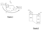
- Figure 1 schematically shows a communication system CS suitable for implementing the method according to an embodiment of the present invention.
- the communication system CS comprises a synchronous transport network TN, that may comprise an SDH, Sonet or OTN network.
- the communication system CS comprises a first Ethernet endpoint EP1 and a second Ethernet endpoint EP2. Both the first Ethernet endpoint EP1 and the second Ethernet endpoint EP2 may be connected to or may be part of respective Ethernet networks, that for simplicity are not shown in Figure 1 .
- the communication system CS comprises a first interface I1 suitable for connecting the first Ethernet endpoint EP1 and the synchronous transport network TN, and a second interface I2 suitable for connecting the second Ethernet endpoint EP2 and the synchronous transport network TN.
- first interface I1 and the second interface I2 may be suitable for performing the above mentioned GFP, as it will be described in further detail herein after.
- the method for transmitting Ethernet packets over the synchronous transport network TN will be described by considering only traffic transmitted from the first Ethernet endpoint EP1 to the second Ethernet endpoint EP2, as indicated by the arrow A shown in Figure 1 .
- Ethernet packets Eth-P When Ethernet packets Eth-P have to be transmitted from the first Ethernet endpoint EP1 to the second Ethernet endpoint EP2, the first Ethernet endpoint EP1 firstly transmits them to the first interface I1.
- the structure of an Ethernet packet Eth-P transmitted from the first Ethernet endpoint EP1 to the first interface I1 is schematically shown in Figure 2 .
- the Ethernet packet Eth-P comprises a header Eth-H, a payload Eth-PI and a frame check sequence Eth-FCS.
- the frame check sequence Eth-FCS is preferably calculated according to what prescribed by the above mentioned IEEE Standard 803.2, Part 3, 9 December 2005, Chapter 3, i.e.: the frame check sequence Eth-FCS is a 4-byte cyclic redundancy check (CRC) code computed as a function of the header Eth-H (except the preamble and the start of frame delimiter) and of the payload Eth-PI.
- CRC cyclic redundancy check
- the first interface I1 When the first interface I1 receives the Ethernet packets Eth-P, it preferably encapsulates them in respective GFP frames GFP-F.
- the structure of a GFP frame generated by the first interface I1 is shown in Figure 2 .
- the GFP frame GFP-F comprises a GFP header GFP-H and a GFP payload GFP-PI.
- the GFP payload GFP-PI preferably comprises an Ethernet packet Eth-P.
- the GFP frame GFP-F is preferably formatted as defined by the above mentioned Recommendation ITU-T G.7041/Y.1303 (12/2003), Chapter 6.
- the GFP header GFP-H (which is termed "core header" in G.7041/Y.1303) comprises a 2-byte PLI (Payload Length Indicator) field and a 2-byte cHEC (Core Header Error Control) field containing a CRC-16 error control code that protects the integrity of the contents of the core header by enabling both single-bit error correction and multi-bit error detection.
- the first interface I1 then maps the GFP frames GFP-F in suitable synchronous tributaries supported by the synchronous transport network TN. For instance, if the synchronous transport network TN is an SDH network, the GPF frames GFP-F may be mapped into SDH VC-n tributaries, such as VC-4 or VC-12 tributaries.
- SDH VC-n tributaries such as VC-4 or VC-12 tributaries.
- the synchronous tributaries are then transmitted to the second interface I2 through the synchronous transport network TN.
- the second interface I2 When the second interface I2 receives the synchronous tributaries, it preferably extracts the GFP frames GFP-F, and then performs de-encapsulation, thus deriving received Ethernet packets Eth-P' corresponding to the Ethernet packets Eth-P transmitted by the first Ethernet endpoint EP1 (except possible bit errors due to transmission, as it will be described in detail herein after).
- the second Ethernet endpoint EP2 transmits the received Ethernet packets Eth-P' to the second Ethernet endpoint EP2.
- the second Ethernet endpoint EP2 preferably further processes the received Ethernet packets Eth-P'. For instance, if the second Ethernet endpoint EP2 is part of an Ethernet network, the second Ethernet endpoint EP2 preferably reads the destination address included in the header Eth-H' of the received Ethernet packets Eth-P', and forwards the received Ethernet packets Eth-P' towards their destination within the Ethernet network. Otherwise, if the second Ethernet endpoint EP2 is the destination of the Ethernet packets Eth-P, it preferably terminates the received Ethernet packets Eth-P', and forwards them to other devices cooperating with it, that process traffic at higher layers of the Internet protocol suite.
- the second Ethernet endpoint EP2 before forwarding or terminating the received Ethernet packets Eth-P', the second Ethernet endpoint EP2 processes the frame check sequence of each received Ethernet packet Eth-P' for correcting possible single-bit errors.
- the operation of calculating the frame check sequence of a given sequence of bytes is a linear operation.
- the error sequence Ei associated to a single-bit error located at the i-th position within the received Ethernet packet Eth-P' has all the bits equal to zero except the bit located at the i-th position.
- position of the bit error indicates the distance between the first bit of the received Ethernet packet Eth-P' and the bit error (i.e. the bit having a value different from the transmitted one).
- the position of the bit error may therefore range from 0 (i.e. the bit error is located at the first bit of the received Ethernet packet Eth-P') to (Nx8)-1.
- step 500 for each error sequence Ei a respective error frame check sequence Ei-FCS is calculated.
- all the error frame check sequences Ei-FCS are calculated by applying to the error sequences Ei the same calculation method applied at the first Ethernet endpoint EP1 for calculating the frame check sequences Eth-FCS of the Ethernet packets Eth-P to be transmitted.
- the error frame check sequences Ei-FCS calculated during step 500 are stored in a table T at the second Ethernet endpoint EP2 (step 501), which is then loaded at the second Ethernet endpoint EP2.
- the table T is schematically shown in Figure 4 .
- the table T comprises a number of rows equal to the number of possible single-bit errors, i.e. Nx8.
- the table T comprises an error frame check sequence Ei-FCS (4 bytes) and an associated position information Ei-Pos indicating that the error frame check sequence Ei-FCS has been calculated on an error sequence Ei indicative of a single-bit error located at the i-th position within the Ethernet packet.
- the position information Ei-Pos comprises a first field indicating the position of the byte comprising the bit error within the received Ethernet packet Eth-P' and a second field indicating the position of the bit error within the byte.
- the second field may comprise 3 bits, since only bit positions 0 to 7 must be represented.
- the error frame check sequences Ei-FCS are arranged within the table T according to a predefined order.
- the error frame check sequences Ei-FCS are arranged according to an increasing order of their values, or according to a decreasing order of their values. This advantageously allows minimizing the maximum time for correcting the single-bit error, has it will be described in detail herein after.
- the off-line phase ends.
- the second Ethernet endpoint EP2 then enters in-line operation, thus starting waiting for reception of Ethernet packets Eth-P' from the second interface I2.
- the second Ethernet endpoint EP2 when it receives an Ethernet packet Eth-P' from the second interface I2 (step 600), it preferably calculates a reception frame check sequence Eth-FCS' on the header Eth-H' and payload Eth-PI' of the received Ethernet packet Eth-P'(step 601).
- the reception frame check sequence Eth-FCS' is calculated by applying the same calculation method applied at the first Ethernet endpoint EP1 for calculating the frame check sequences Eth-FCS of the Ethernet packets Eth-P to be transmitted.
- the second Ethernet endpoint EP2 preferably retrieves the frame check sequence Eth-FCS from the received Ethernet packet Eth-P', and compares the retrieved frame check sequence Eth-FCS with the reception frame check sequences Eth-FCS' calculated during step 601 (step 602).
- the second Ethernet endpoint EP2 determines that the received Ethernet packet Eth-P' does not contain any bit error (step 603), and therefore processes it either by forwarding it towards its destination, or by terminating it (step 604).
- the second Ethernet endpoint EP2 preferably compares the error frame check sequence E-FCS calculated during step 601 with the error frame check sequences Ei-FCS stored in the table T (step 606).
- the second Ethernet endpoint EP2 finds in the table T a stored error frame check sequence Ei-FCS matching with the error frame check sequence E-FCS calculated during step 601 (step 607), it determines that the received Ethernet packet Eth-P' comprises a single-bit error at the i-th position (step 608). In particular, it determines the position at which the single-bit error is located by retrieving the position information Ei-Pos associated to the matching error frame check sequence Ei-FCS. The second Ethernet endpoint EP2 then corrects the bit at the i-th position of the received Ethernet packet Eth-P' (step 609) by changing its value from "0" to "1” or vice versa. The second Ethernet endpoint EP2 then continues processing the received Ethernet packet Eth-P', either by forwarding it towards its destination, or by terminating it (step 604).
- step 607 the second Ethernet endpoint EP2 does not find in the table T any error frame check sequence Ei-FCS matching with the error frame check sequence E-FCS calculated during step 601, it determines that the received Ethernet packet Eth-P' contains a multi-bit error (step 610), and therefore discards it (step 611).
- the quality of service is therefore advantageously increased, without the need of implementing any retransmission of discarded packets or correction of bit errors at higher layers of the Internet protocol suite.
- the above method is capable of correcting single-bit errors at the link layer, since the single-bit error correction is based exclusively on the frame check sequence of the Ethernet packets.
- Implementation at the link layer advantageously allows avoiding development of separated mechanisms for reducing the rate of discarded Ethernet packets at the application layer. This advantageously allows reducing time and costs for developing applications. This also advantageously provides an homogenous solution for reducing the rate of discarded packets, that is shared by all the applications supported by the same link layer.
- the solution uses a standard field (i.e. the frame check sequence) which is defined by the IEEE Standard 803.2. Accordingly, this mechanism is compliant with standard Ethernet endpoints. Indeed, the behavior of the first Ethernet endpoint, acting as transmitter, substantially requires no modifications over the IEEE Standard 803.2. As to the behavior of the second Ethernet endpoint, acting as receiver, the table T has to be loaded and a function has to be added, which is capable of performing the steps shown in the flow chart of Figure 6 . Therefore, advantageously, the rate of discarded packets is reduced without the need of modifying the IEEE Standard 803.2, but simply implementing some standard-compliant additional functions at the receiver side of Ethernet endpoints.
- a standard field i.e. the frame check sequence
- the second Ethernet endpoint EP2 looks up the table T according to a predefined order.
- the error check frame sequences Ei-FCS are arranged according to an increasing order of their values
- the second Ethernet endpoint EP2 preferably compares the error check frame sequence E-FCS calculated during step 601 with the error frame check sequence Ei-FCS stored at the (Nx8)/2-th row of the table T.
- the second Ethernet endpoint determines that the single-bit error is located at the i-th position indicated by the position information Ei-Pos stored at the (Nx8)/2-th row of the table T.
- the second Ethernet endpoint preferably compares it with the error frame check sequence Ei-FCS stored at the (Nx8)/4-th row of the table T. If they match, the second Ethernet endpoint determines that the single-bit error is located at the i-th position indicated by the position information Ei-Pos stored at the (Nx8)/4-th row of the table T. And so on.
- the second Ethernet endpoint if the error check frame sequence E-FCS calculated during step 601 is different from (i.e. higher than) the error frame check sequence Ei-FCS stored at the (Nx8)/2-th row of the table T, the second Ethernet endpoint preferably compares it with the error frame check sequence Ei-FCS stored at the (Nx8)3/4-th row of the table T. If they match, the second Ethernet endpoint determines that the single-bit error is located at the i-th position indicated by the position information Ei-Pos stored at the (Nx8)3/4-th row of the table T. And so on.
- the above described procedure is basically a tree search, that advantageously allows minimizing the maximum number of steps required for completing the search of an error frame check sequence Ei-FCS matching the error frame check sequence E-FCS calculated during step 601.
Landscapes
- Engineering & Computer Science (AREA)
- Computer Networks & Wireless Communication (AREA)
- Signal Processing (AREA)
- Data Exchanges In Wide-Area Networks (AREA)
- Communication Control (AREA)
Abstract
Description
- The present invention relates to the field of synchronous transport networks transporting packets. In particular, the present invention relates to a method for receiving Ethernet packets transported over a synchronous transport network (such as, for instance, an SDH network or a Sonet network). Besides, the present invention relates to an Ethernet endpoint suitable for receiving Ethernet packets from a synchronous transport network, and to a communication system comprising a synchronous transport network and such an Ethernet endpoint.
- As it is known, in a packet-switched network traffic is transmitted in the form of packets. Examples of packet-switched networks are Ethernet networks, IP (Internet Protocol) networks and MPLS (Multi-Protocol Label Switching) networks.
- A packet typically comprises a header with information allowing routing the packet from source to destination and a payload with data to be transmitted. For instance, the IEEE Standard 803.2, Part 3, 9 December 2005, Chapter 3, discloses that an Ethernet packet comprises a header of 22 bytes, a payload with a length ranging from 46 to 1500 bytes and a frame check sequence of 4 bytes. When an Ethernet packet is received at the destination, the frame check sequence is processed for checking whether the header or payload comprises one or more bit errors. In the affirmative, the Ethernet packet is discarded.
- Packets may be transmitted over a synchronous transport network, such as for instance SDH (Synchronous Digital Hierarchy), Sonet (Synchronous Optical NETwork) or OTN (Optical Transport Network).
- For instance, a synchronous transport network may support an Ethernet Private Line (EPL) service, namely a point-to-point interconnection between a first and a second Ethernet endpoints placed at the boundaries of an SDH network, by transporting Ethernet packets from the first Ethernet endpoint to the second Ethernet endpoint, and vice versa.
- Before transmission over the synchronous transport network, packets are typically encapsulated into synchronous frames, which are then mapped into synchronous tributaries supported by the synchronous transport network. On the other hand, after reception from the synchronous transport network, the synchronous frames are extracted from the synchronous tributaries, and then packets are de-encapsulated from the synchronous frames.
- For instance, in case of transport of Ethernet packets from a first Ethernet endpoint to a second Ethernet endpoint over an SDH network, at the first Ethernet endpoint Ethernet packets typically undergo an encapsulation process which is termed GFP (General Framing Procedure). GFP is defined by the International Telecommunication Union (ITU) in the Recommendation ITU-T G.7041/Y.1303 (12/2003). In particular, Chapter 6 of such Recommendation discloses that GFP provides encapsulating Ethernet packets into GFP frames. Each GFP frame typically includes a GFP header and a GFP payload, in turn comprising the Ethernet packet to be transmitted. The GFP frames are then mapped in SDH VC-n tributaries, which are in turn transmitted over the SDH network. Upon reception at the second Ethernet endpoint, GFP frames are extracted from the SDH VC-n tributaries, and the Ethernet packets are de-encapsulated from the GFP frames. As mentioned above, the frame check sequences of the Ethernet packets are then checked, and Ethernet packets with bit errors are discarded.
- The Applicant has noticed that the above solution of receiving Ethernet packets transported over a synchronous transport network has some drawbacks.
- Indeed, a synchronous transport network typically has a bit error rate ranging from 10-12 (in case of optimum transmission conditions) to 10-6 (in case of degraded transmission conditions). When transporting circuit-switched traffic (such as e.g. traffic associated to voice calls), this range of bit error rates gives rise to an acceptable quality of service. However, when the synchronous transport network transports Ethernet packets, due to packets discarding a bit error rate of 10-6 may induce a very high rate of discarded packets, depending on the length of the packets and, more specifically, of their payload. For instance, in case of standard Ethernet packets, the Ethernet payload length ranges from 46 to 1500 bytes. In this case, the rate of discarded packets may be up to 1%. In case of jumbo Ethernet packets, the Ethernet payload length is higher than 1500 bytes. In this case, the rate of discarded packets may be up to 10%.
- These rates of discarded packets are disadvantageously unacceptable, since they induce an unacceptable degradation of the quality of service, in particular when associated to very high latencies introduced by encapsulation in GFP frames, mapping in SDH VC-n tributaries and transmission over the SDH network.
- Possible solutions may be implementing mechanisms for retransmission of the discarded Ethernet packets, or implementing mechanisms for correction of bit errors (e.g. use of Hamming codes or the like) at a higher layer of the Internet protocol suite as defined by the RFC 1122, Chapter 1.1.3 (October 1989).
- According to the RFC 1122, Chapter 1.1.3, the Internet protocol suite comprises four layers: application layer (which is the top layer of the Internet protocol suite), transport layer (providing end-to-end communication services for applications), Internet layer (carrying data from source host to destination host without guarantee of end-to-end delivery) and link layer (also called media access layer, allows a host to interface with directly connected networks). Ethernet is a link layer protocol.
- The above mentioned mechanisms for requesting retransmission of the discarded Ethernet packets and for correcting bit errors are typically implemented at the application layer. For instance, in case Ethernet packets support transmission of real-time traffic by means of the application layer protocol RTP (Real Time Protocol), RTP provides a mechanism for correcting bit errors. On the other hand, in case Ethernet packets support transmission of web page data by means of the application layer protocol HTTP (Hypertext Transfer Protocol), HTTP provides a mechanism for requesting retransmission of discarded Ethernet packets.
- However, implementing mechanisms for requesting retransmission of the discarded Ethernet packets or for correcting bit errors at the application layer is disadvantageous because, each time a new application supported by Ethernet is developed, a corresponding mechanisms must be implemented. This disadvantageously increases times and costs for developing new applications. Moreover, since the various applications are typically developed by different entities, such mechanisms may be very different the ones from the others. This disadvantageously induces a lack of homogeneity in the way the issue of Ethernet discarded packets is managed for the various applications.
- Accordingly, the Applicant has faced the problem of providing a method for receiving Ethernet packets transported over a synchronous transport network which overcomes the aforesaid problem.
- In particular, the Applicant has faced the problem of providing a method for receiving Ethernet packets transported over a synchronous transport network which reduces the rate of discarded packets at the link layer of the Internet protocol suite (i.e. the layer of Ethernet), so that the mechanism for reducing the rate of discarded packets is common to all the applications supported by the same link layer protocol.
- According to a first aspect, the present invention provides a method for receiving Ethernet packets transported over a synchronous transport network, each of the Ethernet packets having a header, a payload and a frame check sequence, the method being characterized in that receiving comprises processing the frame check sequence of the Ethernet packets for correcting possible single-bit errors affecting the Ethernet packets.
- Preferably, processing comprises:
- a) calculating a reception frame check sequence on a header and a payload of a received Ethernet packet;
- b) comparing the reception frame check sequence with the frame check sequence comprised in the received Ethernet packet and,
- c) if the reception frame check sequence matches with the frame check sequence, determining that the received Ethernet packet does not comprise any bit error.
- Preferably, processing further comprises:
- d) storing a plurality of error check frame sequences, each of the plurality of error check frame sequences being calculated on an error sequence indicating a position of a single-bit error possibly affecting the Ethernet packets.
- Profitably, processing further comprises:
- e) if the reception frame check sequence does not match with the frame check sequence, processing the frame check sequence and the reception frame check sequence thus generating a further error frame check sequence;
- f) determining whether one of the plurality of error check frame sequences matches the further error frame check sequence;
- g) in the affirmative, correcting a bit of the received Ethernet packet located at a position indicated by an error sequence on which the one of the plurality of error check frame sequences was calculated; and
- h) in the negative, determining that the received Ethernet packet comprises a multi-bit error, and discarding the received Ethernet packet.
- Preferably, step f) comprises:
- arranging the plurality of error check frame sequences according to their values; and
- performing a tree search among the plurality of error check frame sequences arranged according to their values.
Profitably, step d) comprises generating, for each of the plurality of error check frame sequences, a respective position information indicative of the position of the single-bit error.
Preferably, the step of generating comprises including in the position information:- a first field indicating a position of a byte including the bit error within an Ethernet packet; and
- a second field indicating a position of the bit error within the byte.
- According to a second aspect, the present invention provides an Ethernet endpoint suitable for being connected to a synchronous transport network for receiving Ethernet packets from the synchronous transport network, each of the Ethernet packets having a header, a payload and a frame check sequence, the Ethernet endpoint being characterized in that it is suitable for processing the frame check sequence of the Ethernet packets for correcting possible single-bit errors affecting the Ethernet packets.
- According to a third aspect, the present invention provides a communication system comprising a synchronous transport network and an Ethernet endpoint, the Ethernet endpoint being connected to the synchronous transport network for receiving Ethernet packets from the synchronous transport network, each of the Ethernet packets having a header, a payload and a frame check sequence, the communication system being characterized in that the Ethernet endpoint is as set forth above.
- The present invention will be better understood by reading the following detailed description, given by way of example and not of limitation, to be read by referring to the accompanying drawings, wherein:
-
Figure 1 schematically shows a communication system suitable for implementing the method according to an embodiment of the present invention; -
Figure 2 schematically shows the structure of an Ethernet packet and a GFP frame encapsulating the Ethernet packet; -
Figure 3 schematically shows the relationship between the check frame sequences of a transmitted Ethernet packet, a received Ethernet packet and an error sequence; -
Figure 4 shows a table allowing to implement the method according to an embodiment of the present invention; -
Figure 5 is a flow chart of the method according to an embodiment of the present invention, during off-line operation; and -
Figure 6 is a flow chart of the method according to an embodiment of the present invention, during in-line operation. -
Figure 1 schematically shows a communication system CS suitable for implementing the method according to an embodiment of the present invention. - The communication system CS comprises a synchronous transport network TN, that may comprise an SDH, Sonet or OTN network.
- Further, the communication system CS comprises a first Ethernet endpoint EP1 and a second Ethernet endpoint EP2. Both the first Ethernet endpoint EP1 and the second Ethernet endpoint EP2 may be connected to or may be part of respective Ethernet networks, that for simplicity are not shown in
Figure 1 . - Further, the communication system CS comprises a first interface I1 suitable for connecting the first Ethernet endpoint EP1 and the synchronous transport network TN, and a second interface I2 suitable for connecting the second Ethernet endpoint EP2 and the synchronous transport network TN. For instance, both the first interface I1 and the second interface I2 may be suitable for performing the above mentioned GFP, as it will be described in further detail herein after.
- By way of example, the method for transmitting Ethernet packets over the synchronous transport network TN will be described by considering only traffic transmitted from the first Ethernet endpoint EP1 to the second Ethernet endpoint EP2, as indicated by the arrow A shown in
Figure 1 . This is merely exemplary, since the method is the same also for traffic transmitted from the second Ethernet endpoint EP2 to the first Ethernet endpoint EP1. - When Ethernet packets Eth-P have to be transmitted from the first Ethernet endpoint EP1 to the second Ethernet endpoint EP2, the first Ethernet endpoint EP1 firstly transmits them to the first interface I1. The structure of an Ethernet packet Eth-P transmitted from the first Ethernet endpoint EP1 to the first interface I1 is schematically shown in
Figure 2 . As mentioned above, the Ethernet packet Eth-P comprises a header Eth-H, a payload Eth-PI and a frame check sequence Eth-FCS. - The frame check sequence Eth-FCS is preferably calculated according to what prescribed by the above mentioned IEEE Standard 803.2, Part 3, 9 December 2005, Chapter 3, i.e.: the frame check sequence Eth-FCS is a 4-byte cyclic redundancy check (CRC) code computed as a function of the header Eth-H (except the preamble and the start of frame delimiter) and of the payload Eth-PI. The computation is performed by using the following generating polynomial:
G(x) = x32+X26+x23+x22+x16+x12+x11+x10+x8+x7+x5+x4+x2+x+1 - When the first interface I1 receives the Ethernet packets Eth-P, it preferably encapsulates them in respective GFP frames GFP-F. The structure of a GFP frame generated by the first interface I1 is shown in
Figure 2 . As mentioned above, the GFP frame GFP-F comprises a GFP header GFP-H and a GFP payload GFP-PI. The GFP payload GFP-PI preferably comprises an Ethernet packet Eth-P. - The GFP frame GFP-F is preferably formatted as defined by the above mentioned Recommendation ITU-T G.7041/Y.1303 (12/2003), Chapter 6. In particular, the GFP header GFP-H (which is termed "core header" in G.7041/Y.1303) comprises a 2-byte PLI (Payload Length Indicator) field and a 2-byte cHEC (Core Header Error Control) field containing a CRC-16 error control code that protects the integrity of the contents of the core header by enabling both single-bit error correction and multi-bit error detection.
- The first interface I1 then maps the GFP frames GFP-F in suitable synchronous tributaries supported by the synchronous transport network TN. For instance, if the synchronous transport network TN is an SDH network, the GPF frames GFP-F may be mapped into SDH VC-n tributaries, such as VC-4 or VC-12 tributaries.
- The synchronous tributaries are then transmitted to the second interface I2 through the synchronous transport network TN.
- When the second interface I2 receives the synchronous tributaries, it preferably extracts the GFP frames GFP-F, and then performs de-encapsulation, thus deriving received Ethernet packets Eth-P' corresponding to the Ethernet packets Eth-P transmitted by the first Ethernet endpoint EP1 (except possible bit errors due to transmission, as it will be described in detail herein after).
- Finally, the second Ethernet endpoint EP2 transmits the received Ethernet packets Eth-P' to the second Ethernet endpoint EP2.
- The second Ethernet endpoint EP2 preferably further processes the received Ethernet packets Eth-P'. For instance, if the second Ethernet endpoint EP2 is part of an Ethernet network, the second Ethernet endpoint EP2 preferably reads the destination address included in the header Eth-H' of the received Ethernet packets Eth-P', and forwards the received Ethernet packets Eth-P' towards their destination within the Ethernet network. Otherwise, if the second Ethernet endpoint EP2 is the destination of the Ethernet packets Eth-P, it preferably terminates the received Ethernet packets Eth-P', and forwards them to other devices cooperating with it, that process traffic at higher layers of the Internet protocol suite.
- According to embodiments of the present invention, before forwarding or terminating the received Ethernet packets Eth-P', the second Ethernet endpoint EP2 processes the frame check sequence of each received Ethernet packet Eth-P' for correcting possible single-bit errors.
- In particular, by referring to
Figure 3 , the Applicant has noticed that a sequence of bytes S' affected by a bit error (either a single-bit error or a multi-bit error) may be seen as the binary sum of an error-free sequence of bytes S and an error sequence E, i.e. S'=S⊕E, where ⊕ indicates the exclusive OR (XOR) logic operation. Further, the Applicant has noticed that the operation of calculating the frame check sequence of a given sequence of bytes is a linear operation. Accordingly, the frame check sequence FCS' of the sequence of bytes S' affected by bit errors is equal to the binary sum of the frame check sequence FCS of the error-free sequence of bytes S and the frame check sequence E-FCS of the error sequence E, i.e.:
- By assuming that:
- the error-free sequence of bytes S corresponds to the header Eth-H and payload Eth-PI of an Ethernet packet Eth-P transmitted by the first Ethernet endpoint EP1;
- the sequence of bytes S' affected by a bit error corresponds to the header Eth-H' and payload Eth-PI' of the received Ethernet packet Eth-P' corresponding to the transmitted Ethernet packet Eth-P; and
- the frame check sequence comprised in the received Ethernet packet Eth-P' is equal to the frame check sequence Eth-FCS comprised in the corresponding Ethernet packet Eth-P (i.e. the frame check sequence is not affected by bit errors),
the second Ethernet endpoint EP2 may correct possible single-bit errors from the received Ethernet packets Eth-P' by processing their frame check sequences Eth-FCS. - In particular, by referring to
Figure 5 , during an off-line operation phase, a determination is performed of all possible single-bit errors that may affect the received Ethernet packets Eth-P' and that may be located either in the header Eth-H' or in the payload Eth-PI'. If N is the overall number of bytes of the header Eth-H' and payload Eth-PI', the number of possible single-bit errors is Nx8. Then, for each possible single-bit error, a respective error sequence Ei is generated (step 500). Each error sequence Ei preferably is a sequence of N bytes. Preferably, the error sequence Ei associated to a single-bit error located at the i-th position within the received Ethernet packet Eth-P' has all the bits equal to zero except the bit located at the i-th position. - In the context of the present description, the expression "position of the bit error" indicates the distance between the first bit of the received Ethernet packet Eth-P' and the bit error (i.e. the bit having a value different from the transmitted one). The position of the bit error may therefore range from 0 (i.e. the bit error is located at the first bit of the received Ethernet packet Eth-P') to (Nx8)-1.
- During
step 500, for each error sequence Ei a respective error frame check sequence Ei-FCS is calculated. Preferably, duringstep 500, all the error frame check sequences Ei-FCS are calculated by applying to the error sequences Ei the same calculation method applied at the first Ethernet endpoint EP1 for calculating the frame check sequences Eth-FCS of the Ethernet packets Eth-P to be transmitted. In particular, if the frame check sequence Eth-FCS is calculated according to what prescribed by the above mentioned IEEE Standard 803.2, Part 3, 9 December 2005, Chapter 3, also the error frame check sequences Ei-FCS are calculated as 4-byte cyclic redundancy check (CRC) codes by using the following generating polynomial:
G(x) = x32+X26+x23+x22+x16+x12+x11+x10+x8+x7+x5+x4+x2+x+1 - Then, always during the off-line phase, the error frame check sequences Ei-FCS calculated during
step 500 are stored in a table T at the second Ethernet endpoint EP2 (step 501), which is then loaded at the second Ethernet endpoint EP2. - The table T is schematically shown in
Figure 4 . The table T comprises a number of rows equal to the number of possible single-bit errors, i.e. Nx8. For each row, the table T comprises an error frame check sequence Ei-FCS (4 bytes) and an associated position information Ei-Pos indicating that the error frame check sequence Ei-FCS has been calculated on an error sequence Ei indicative of a single-bit error located at the i-th position within the Ethernet packet. Preferably, the position information Ei-Pos comprises a first field indicating the position of the byte comprising the bit error within the received Ethernet packet Eth-P' and a second field indicating the position of the bit error within the byte. For instance, the first field may comprise 11 bits, and is therefore suitable for representing byte positions 0 to 211-1=2047. On the other hand, the second field may comprise 3 bits, since only bit positions 0 to 7 must be represented. - Preferably, the error frame check sequences Ei-FCS are arranged within the table T according to a predefined order. Preferably, the error frame check sequences Ei-FCS are arranged according to an increasing order of their values, or according to a decreasing order of their values. This advantageously allows minimizing the maximum time for correcting the single-bit error, has it will be described in detail herein after.
- After the table T has been loaded at the second Ethernet endpoint EP2, the off-line phase ends. The second Ethernet endpoint EP2 then enters in-line operation, thus starting waiting for reception of Ethernet packets Eth-P' from the second interface I2.
- By referring to the flow chart of
Figure 6 , when the second Ethernet endpoint EP2 receives an Ethernet packet Eth-P' from the second interface I2 (step 600), it preferably calculates a reception frame check sequence Eth-FCS' on the header Eth-H' and payload Eth-PI' of the received Ethernet packet Eth-P'(step 601). Preferably, the reception frame check sequence Eth-FCS' is calculated by applying the same calculation method applied at the first Ethernet endpoint EP1 for calculating the frame check sequences Eth-FCS of the Ethernet packets Eth-P to be transmitted. In particular, if the frame check sequence Eth-FCS is calculated according to what prescribed by the above mentioned IEEE Standard 803.2, Part 3, 9 December 2005, Chapter 3, also the reception frame check sequences Eth-FCS' are calculated as 4-byte cyclic redundancy check (CRC) codes by using the following generating polynomial:
G(x) = x32+X26+x23+x22+x16+x12+x11+x10+x8+x7+x5+x4+x2+x+1 - Then, the second Ethernet endpoint EP2 preferably retrieves the frame check sequence Eth-FCS from the received Ethernet packet Eth-P', and compares the retrieved frame check sequence Eth-FCS with the reception frame check sequences Eth-FCS' calculated during step 601 (step 602).
- If the retrieved frame check sequence Eth-FCS is equal to the reception frame check sequences Eth-FCS' calculated during
step 601, the second Ethernet endpoint EP2 determines that the received Ethernet packet Eth-P' does not contain any bit error (step 603), and therefore processes it either by forwarding it towards its destination, or by terminating it (step 604). - Otherwise, if the retrieved frame check sequence Eth-FCS is different from the reception frame check sequences Eth-FCS' calculated during
step 601, the second Ethernet endpoint EP2 preferably calculates an error frame check sequence E-FCS by processing the retrieved frame check sequence Eth-FCS and the calculated reception check frame sequence Eth-FCS' (step 605) according to the following equation:
- Then, the second Ethernet endpoint EP2 preferably compares the error frame check sequence E-FCS calculated during
step 601 with the error frame check sequences Ei-FCS stored in the table T (step 606). - If the second Ethernet endpoint EP2 finds in the table T a stored error frame check sequence Ei-FCS matching with the error frame check sequence E-FCS calculated during step 601 (step 607), it determines that the received Ethernet packet Eth-P' comprises a single-bit error at the i-th position (step 608). In particular, it determines the position at which the single-bit error is located by retrieving the position information Ei-Pos associated to the matching error frame check sequence Ei-FCS. The second Ethernet endpoint EP2 then corrects the bit at the i-th position of the received Ethernet packet Eth-P' (step 609) by changing its value from "0" to "1" or vice versa. The second Ethernet endpoint EP2 then continues processing the received Ethernet packet Eth-P', either by forwarding it towards its destination, or by terminating it (step 604).
- Otherwise, if during
step 607 the second Ethernet endpoint EP2 does not find in the table T any error frame check sequence Ei-FCS matching with the error frame check sequence E-FCS calculated duringstep 601, it determines that the received Ethernet packet Eth-P' contains a multi-bit error (step 610), and therefore discards it (step 611). - The quality of service is therefore advantageously increased, without the need of implementing any retransmission of discarded packets or correction of bit errors at higher layers of the Internet protocol suite.
- Indeed, the above method is capable of correcting single-bit errors at the link layer, since the single-bit error correction is based exclusively on the frame check sequence of the Ethernet packets. Implementation at the link layer advantageously allows avoiding development of separated mechanisms for reducing the rate of discarded Ethernet packets at the application layer. This advantageously allows reducing time and costs for developing applications. This also advantageously provides an homogenous solution for reducing the rate of discarded packets, that is shared by all the applications supported by the same link layer.
- Besides, advantageously, the solution uses a standard field (i.e. the frame check sequence) which is defined by the IEEE Standard 803.2. Accordingly, this mechanism is compliant with standard Ethernet endpoints. Indeed, the behavior of the first Ethernet endpoint, acting as transmitter, substantially requires no modifications over the IEEE Standard 803.2. As to the behavior of the second Ethernet endpoint, acting as receiver, the table T has to be loaded and a function has to be added, which is capable of performing the steps shown in the flow chart of
Figure 6 . Therefore, advantageously, the rate of discarded packets is reduced without the need of modifying the IEEE Standard 803.2, but simply implementing some standard-compliant additional functions at the receiver side of Ethernet endpoints. - Preferably, for performing
step 606, the second Ethernet endpoint EP2 looks up the table T according to a predefined order. In particular, under the assumption that (as mentioned above), the error check frame sequences Ei-FCS are arranged according to an increasing order of their values, after calculation of the error frame check sequence E-FCS the second Ethernet endpoint EP2 preferably compares the error check frame sequence E-FCS calculated duringstep 601 with the error frame check sequence Ei-FCS stored at the (Nx8)/2-th row of the table T. - If they match, the second Ethernet endpoint determines that the single-bit error is located at the i-th position indicated by the position information Ei-Pos stored at the (Nx8)/2-th row of the table T.
- Otherwise, if the error check frame sequence E-FCS calculated during
step 601 is different from (i.e. lower than) the error frame check sequence Ei-FCS stored at the (Nx8)/2-th row of the table T, the second Ethernet endpoint preferably compares it with the error frame check sequence Ei-FCS stored at the (Nx8)/4-th row of the table T. If they match, the second Ethernet endpoint determines that the single-bit error is located at the i-th position indicated by the position information Ei-Pos stored at the (Nx8)/4-th row of the table T. And so on. - On the other hand, if the error check frame sequence E-FCS calculated during
step 601 is different from (i.e. higher than) the error frame check sequence Ei-FCS stored at the (Nx8)/2-th row of the table T, the second Ethernet endpoint preferably compares it with the error frame check sequence Ei-FCS stored at the (Nx8)3/4-th row of the table T. If they match, the second Ethernet endpoint determines that the single-bit error is located at the i-th position indicated by the position information Ei-Pos stored at the (Nx8)3/4-th row of the table T. And so on. - The above described procedure is basically a tree search, that advantageously allows minimizing the maximum number of steps required for completing the search of an error frame check sequence Ei-FCS matching the error frame check sequence E-FCS calculated during
step 601. The maximum number of steps required for completing the search is indeed log2(Nx8). For instance, if the overall number of bytes of the header Eth-H and payload Eth-PI of an Ethernet packet Eth-P is 1024, the number of possible single-bit errors is 1024x8=8192. Accordingly, the maximum number of steps required for completing the search is log2(8192x8)=14. Since each step is performed at a respective clock cycle, the maximum time required for completing the search is advantageously fixed and predictable.
Claims (15)
- A method for receiving Ethernet packets (Eth-P') transported over a synchronous transport network (TN), each of said Ethernet packets (Eth-P') having a header (Eth-H), a payload (Eth-PI) and a frame check sequence (Eth-FCS),
said method being characterized in that said receiving comprises processing said frame check sequence (Eth-FCS) of said Ethernet packets (Eth-P') for correcting possible single-bit errors affecting said Ethernet packets (Eth-P'). - The method according to claim 1, wherein said processing comprises:a) calculating (601) a reception frame check sequence (Eth-FCS') on a header and a payload of a received Ethernet packet (Eth-P');b) comparing (602) said reception frame check sequence (Eth-FCS') with said frame check sequence (Eth-FCS) comprised in said received Ethernet packet (Eth-P') and,c) if said reception frame check sequence (Eth-FCS') matches with said frame check sequence (Eth-FCS), determining (603) that said received Ethernet packet (Eth-P') does not comprise any bit error.
- The method according to claim 2, wherein said processing further comprises:d) storing (500, 501) a plurality of error check frame sequences (Ei-FCS), each of said plurality of error check frame sequences (Ei-FCS) being calculated on an error sequence (Ei) indicating a position of a single-bit error possibly affecting said Ethernet packets.
- The method according to claim 3, wherein said processing further comprises:e) if said reception frame check sequence (Eth-FCS') does not match with said frame check sequence (Eth-FCS), processing (605) said frame check sequence (Eth-FCS) and said reception frame check sequence (Eth-FCS') thus generating a further error frame check sequence (E-FCS);f) determining (606, 607) whether one of said plurality of error check frame sequences (Ei-FCS) matches said further error frame check sequence (E-FCS);g) in the affirmative, correcting (609) a bit of said received Ethernet packet (Eth-P') located at a position indicated by an error sequence (Ei) on which said one of said plurality of error check frame sequences (Ei-FCS) was calculated; andh) in the negative, determining (610) that said received Ethernet packet (Eth-P') comprises a multi-bit error, and discarding (611) said received Ethernet packet (Eth-P').
- The method according to claim 3 or 4, wherein said step f) comprises:- arranging said plurality of error check frame sequences (Ei-FCS) according to their values; and- performing a tree search among said plurality of error check frame sequences (Ei-FCS) arranged according to their values.
- The method according to any of claims 3 to 5, wherein said step d) comprises generating, for each of said plurality of error check frame sequences (Ei-FCS), a respective position information (Ei-Pos) indicative of said position of said single-bit error.
- The method according to claim 6, wherein said generating comprises including in said position information (Ei-Pos):- a first field indicating a position of a byte including said bit error within an Ethernet packet; and- a second field indicating a position of said bit error within said byte.
- An Ethernet endpoint (EP2) suitable for being connected to a synchronous transport network (TN) for receiving Ethernet packets (Eth-P') from said synchronous transport network (TN), each of said Ethernet packets (Eth-P') having a header (Eth-H), a payload (Eth-PI) and a frame check sequence (Eth-FCS),
said Ethernet endpoint (EP2) being characterized in that it is suitable for processing said frame check sequence (Eth-FCS) of said Ethernet packets (Eth-P') for correcting possible single-bit errors affecting said Ethernet packets (Eth-P'). - The Ethernet endpoint (EP2) according to claim 8, wherein it is suitable for processing by performing the following operations:a) calculating (601) a reception frame check sequence (Eth-FCS') on a header and a payload of an Ethernet packet (Eth-P');b) comparing (602) said reception frame check sequence (Eth-FCS') with said frame check sequence (Eth-FCS) comprised in said received Ethernet packet (Eth-P') and,c) if said reception frame check sequence (Eth-FCS') matches with said frame check sequence (Eth-FCS), determining (603) that said Ethernet packet (Eth-P') does not comprise any bit error.
- The Ethernet endpoint (EP2) according to claim 9, wherein it is suitable for processing by further performing the following operations:d) storing (500, 501) a plurality of error check frame sequences (Ei-FCS), each of said plurality of error check frame sequences (Ei-FCS) being calculated on an error sequence (Ei) indicating a position of a single-bit error possibly affecting said Ethernet packets.
- The Ethernet endpoint (EP2) according to claim 10, wherein it is suitable for processing by further performing the following operations:e) if said reception frame check sequence (Eth-FCS') does not match with said frame check sequence (Eth-FCS), processing (605) said frame check sequence (Eth-FCS) and said reception frame check sequence (Eth-FCS') thus generating a further error frame check sequence (E-FCS);f) determining (606, 607) whether one of said plurality of error check frame sequences (Ei-FCS) matches said further error frame check sequence (E-FCS);g) in the affirmative, correcting (609) a bit of said Ethernet packet (Eth-P') located at a position indicated by an error sequence (Ei) on which said one of said plurality of error check frame sequences (Ei-FCS) was calculated; andh) in the negative, determining (610) that said Ethernet packet (Eth-P') comprises a multi-bit error, and discarding (611) said Ethernet packet (Eth-P').
- The Ethernet endpoint (EP2) according to claim 10 or 11, wherein it is suitable for performing said operation f) by performing the following operations:- arranging said plurality of error check frame sequences (Ei-FCS) according to their values; and- performing a tree search among said plurality of error check frame sequences (Ei-FCS) arranged according to their values.
- The Ethernet endpoint (EP2) according to any of claims 10 to 12, wherein it is suitable for performing said operation d) by generating, for each of said plurality of error check frame sequences (Ei-FCS), a respective position information (Ei-Pos) indicative of said position of said single-bit error.
- The Ethernet endpoint (EP2) according to claim 13, wherein it is suitable for performing said generating by including in said position information (Ei-Pos):- a first field indicating a position of a byte including said bit error within an Ethernet packet; and- a second field indicating a position of said bit error within said byte.
- A communication system (CS) comprising a synchronous transport network (TN) and an Ethernet endpoint (EP2), said Ethernet endpoint (EP2) being connected to said synchronous transport network (TN) for receiving Ethernet packets (Eth-P') from said synchronous transport network (TN), each of said Ethernet packets (Eth-P, Eth-P') having a header (Eth-H), a payload (Eth-PI) and a frame check sequence (Eth-FCS), said communication system (CS) being characterized in that said Ethernet endpoint (EP2) is according to any of claims 8 to 14.
Priority Applications (1)
| Application Number | Priority Date | Filing Date | Title |
|---|---|---|---|
| EP20090305021 EP2207287B1 (en) | 2009-01-09 | 2009-01-09 | Reception of ethernet packets transported over a synchronous transport network |
Applications Claiming Priority (1)
| Application Number | Priority Date | Filing Date | Title |
|---|---|---|---|
| EP20090305021 EP2207287B1 (en) | 2009-01-09 | 2009-01-09 | Reception of ethernet packets transported over a synchronous transport network |
Publications (3)
| Publication Number | Publication Date |
|---|---|
| EP2207287A1 true EP2207287A1 (en) | 2010-07-14 |
| EP2207287A8 EP2207287A8 (en) | 2010-08-18 |
| EP2207287B1 EP2207287B1 (en) | 2012-09-05 |
Family
ID=40720072
Family Applications (1)
| Application Number | Title | Priority Date | Filing Date |
|---|---|---|---|
| EP20090305021 Active EP2207287B1 (en) | 2009-01-09 | 2009-01-09 | Reception of ethernet packets transported over a synchronous transport network |
Country Status (1)
| Country | Link |
|---|---|
| EP (1) | EP2207287B1 (en) |
Cited By (1)
| Publication number | Priority date | Publication date | Assignee | Title |
|---|---|---|---|---|
| WO2012009926A1 (en) * | 2010-07-19 | 2012-01-26 | 中兴通讯股份有限公司 | Method, system and equipment for monitoring error code of common public radio interface (cpri) link |
Citations (3)
| Publication number | Priority date | Publication date | Assignee | Title |
|---|---|---|---|---|
| WO2004073222A1 (en) * | 2003-02-12 | 2004-08-26 | Cisco Technology, Inc. | Efficient framing procedure for variable length packets |
| EP1628402A1 (en) | 2004-08-19 | 2006-02-22 | Alcatel | Correction of error propagation caused by scrambling with subsequent forward error correction |
| US20070127487A1 (en) | 2005-12-07 | 2007-06-07 | Electronics And Telecommunications Research Institute | Method for managing service bandwidth by customer port and EPON system using the same |
-
2009
- 2009-01-09 EP EP20090305021 patent/EP2207287B1/en active Active
Patent Citations (3)
| Publication number | Priority date | Publication date | Assignee | Title |
|---|---|---|---|---|
| WO2004073222A1 (en) * | 2003-02-12 | 2004-08-26 | Cisco Technology, Inc. | Efficient framing procedure for variable length packets |
| EP1628402A1 (en) | 2004-08-19 | 2006-02-22 | Alcatel | Correction of error propagation caused by scrambling with subsequent forward error correction |
| US20070127487A1 (en) | 2005-12-07 | 2007-06-07 | Electronics And Telecommunications Research Institute | Method for managing service bandwidth by customer port and EPON system using the same |
Cited By (4)
| Publication number | Priority date | Publication date | Assignee | Title |
|---|---|---|---|---|
| WO2012009926A1 (en) * | 2010-07-19 | 2012-01-26 | 中兴通讯股份有限公司 | Method, system and equipment for monitoring error code of common public radio interface (cpri) link |
| CN102340368A (en) * | 2010-07-19 | 2012-02-01 | 中兴通讯股份有限公司 | Method, system and device for monitoring error codes in CPRI (Common Public Radio Interface) link |
| US8510627B2 (en) | 2010-07-19 | 2013-08-13 | Zte Corporation | Method, system and device for monitoring error code of common public radio interface (CPRI) link |
| CN102340368B (en) * | 2010-07-19 | 2014-07-02 | 中兴通讯股份有限公司 | Method, system and device for monitoring error codes in CPRI (Common Public Radio Interface) link |
Also Published As
| Publication number | Publication date |
|---|---|
| EP2207287B1 (en) | 2012-09-05 |
| EP2207287A8 (en) | 2010-08-18 |
Similar Documents
| Publication | Publication Date | Title |
|---|---|---|
| EP1871068B1 (en) | Method and device for generic framing procedure encapsulation | |
| US7298694B2 (en) | Apparatus and method for GFP frame transfer | |
| US8243619B2 (en) | Smart mechanism for multi-client bidirectional optical channel protection scheme | |
| CN1748381B (en) | Efficient Framing Method for Variable Length Packets | |
| US7519080B2 (en) | Fibre channel frame-mode GFP with distributed delimiter | |
| CN101160727B (en) | Method and device for transparent GFP (generic framing process) superblock error correction | |
| WO2020247003A1 (en) | Method for providing path signal overhead in the 64b/66b character stream of an itu-t metro transport network | |
| WO2021121352A1 (en) | Data transmission method and apparatus | |
| CN102195750B (en) | Data transfer device and data transfer system | |
| US12132568B2 (en) | Block processing method, node, and medium | |
| US7684419B2 (en) | Ethernet encapsulation over optical transport network | |
| CN110637424A (en) | Encapsulation header design in passive optical network | |
| US8644347B2 (en) | Transporting optical data units in an optical transport network | |
| US8369226B2 (en) | Method and device of processing a generic framing procedure frame | |
| US20050169275A1 (en) | Method for transmitting multi-protocol label switch protocol data units | |
| EP2207287B1 (en) | Reception of ethernet packets transported over a synchronous transport network | |
| US20060126662A1 (en) | Methods for sending and receiving network management messages and/or control messages | |
| JP7346662B2 (en) | Data transmission methods and transfer devices | |
| CN110830153B (en) | Method for receiving code block stream, method for transmitting code block stream and communication device | |
| KR20120020172A (en) | Maintaining time-division multiplexing over pseudowire connections during network outages | |
| JPH01170140A (en) | Data communication system | |
| WO2025001405A1 (en) | Method and apparatus for service processing in optical transport network, device, and storage medium | |
| EP2048828A1 (en) | Method and systems for data transmission over packet networks, corresponding computer program product | |
| SECTOR et al. | ITU-Tg. 8312 |
Legal Events
| Date | Code | Title | Description |
|---|---|---|---|
| PUAI | Public reference made under article 153(3) epc to a published international application that has entered the european phase |
Free format text: ORIGINAL CODE: 0009012 |
|
| 17P | Request for examination filed |
Effective date: 20091103 |
|
| AK | Designated contracting states |
Kind code of ref document: A1 Designated state(s): AT BE BG CH CY CZ DE DK EE ES FI FR GB GR HR HU IE IS IT LI LT LU LV MC MK MT NL NO PL PT RO SE SI SK TR |
|
| AX | Request for extension of the european patent |
Extension state: AL BA RS |
|
| 17Q | First examination report despatched |
Effective date: 20101129 |
|
| AKX | Designation fees paid |
Designated state(s): AT BE BG CH CY CZ DE DK EE ES FI FR GB GR HR HU IE IS IT LI LT LU LV MC MK MT NL NO PL PT RO SE SI SK TR |
|
| RAP1 | Party data changed (applicant data changed or rights of an application transferred) |
Owner name: ALCATEL LUCENT |
|
| GRAP | Despatch of communication of intention to grant a patent |
Free format text: ORIGINAL CODE: EPIDOSNIGR1 |
|
| GRAS | Grant fee paid |
Free format text: ORIGINAL CODE: EPIDOSNIGR3 |
|
| GRAA | (expected) grant |
Free format text: ORIGINAL CODE: 0009210 |
|
| AK | Designated contracting states |
Kind code of ref document: B1 Designated state(s): AT BE BG CH CY CZ DE DK EE ES FI FR GB GR HR HU IE IS IT LI LT LU LV MC MK MT NL NO PL PT RO SE SI SK TR |
|
| REG | Reference to a national code |
Ref country code: GB Ref legal event code: FG4D |
|
| REG | Reference to a national code |
Ref country code: CH Ref legal event code: EP |
|
| REG | Reference to a national code |
Ref country code: AT Ref legal event code: REF Ref document number: 574521 Country of ref document: AT Kind code of ref document: T Effective date: 20120915 |
|
| REG | Reference to a national code |
Ref country code: IE Ref legal event code: FG4D |
|
| REG | Reference to a national code |
Ref country code: DE Ref legal event code: R096 Ref document number: 602009009441 Country of ref document: DE Effective date: 20121031 |
|
| REG | Reference to a national code |
Ref country code: AT Ref legal event code: MK05 Ref document number: 574521 Country of ref document: AT Kind code of ref document: T Effective date: 20120905 |
|
| REG | Reference to a national code |
Ref country code: NL Ref legal event code: VDEP Effective date: 20120905 |
|
| PG25 | Lapsed in a contracting state [announced via postgrant information from national office to epo] |
Ref country code: AT Free format text: LAPSE BECAUSE OF FAILURE TO SUBMIT A TRANSLATION OF THE DESCRIPTION OR TO PAY THE FEE WITHIN THE PRESCRIBED TIME-LIMIT Effective date: 20120905 Ref country code: LT Free format text: LAPSE BECAUSE OF FAILURE TO SUBMIT A TRANSLATION OF THE DESCRIPTION OR TO PAY THE FEE WITHIN THE PRESCRIBED TIME-LIMIT Effective date: 20120905 Ref country code: CY Free format text: LAPSE BECAUSE OF FAILURE TO SUBMIT A TRANSLATION OF THE DESCRIPTION OR TO PAY THE FEE WITHIN THE PRESCRIBED TIME-LIMIT Effective date: 20120905 Ref country code: FI Free format text: LAPSE BECAUSE OF FAILURE TO SUBMIT A TRANSLATION OF THE DESCRIPTION OR TO PAY THE FEE WITHIN THE PRESCRIBED TIME-LIMIT Effective date: 20120905 Ref country code: NO Free format text: LAPSE BECAUSE OF FAILURE TO SUBMIT A TRANSLATION OF THE DESCRIPTION OR TO PAY THE FEE WITHIN THE PRESCRIBED TIME-LIMIT Effective date: 20121205 Ref country code: HR Free format text: LAPSE BECAUSE OF FAILURE TO SUBMIT A TRANSLATION OF THE DESCRIPTION OR TO PAY THE FEE WITHIN THE PRESCRIBED TIME-LIMIT Effective date: 20120905 |
|
| REG | Reference to a national code |
Ref country code: LT Ref legal event code: MG4D Effective date: 20120905 |
|
| PG25 | Lapsed in a contracting state [announced via postgrant information from national office to epo] |
Ref country code: GR Free format text: LAPSE BECAUSE OF FAILURE TO SUBMIT A TRANSLATION OF THE DESCRIPTION OR TO PAY THE FEE WITHIN THE PRESCRIBED TIME-LIMIT Effective date: 20121206 Ref country code: SI Free format text: LAPSE BECAUSE OF FAILURE TO SUBMIT A TRANSLATION OF THE DESCRIPTION OR TO PAY THE FEE WITHIN THE PRESCRIBED TIME-LIMIT Effective date: 20120905 Ref country code: LV Free format text: LAPSE BECAUSE OF FAILURE TO SUBMIT A TRANSLATION OF THE DESCRIPTION OR TO PAY THE FEE WITHIN THE PRESCRIBED TIME-LIMIT Effective date: 20120905 Ref country code: SE Free format text: LAPSE BECAUSE OF FAILURE TO SUBMIT A TRANSLATION OF THE DESCRIPTION OR TO PAY THE FEE WITHIN THE PRESCRIBED TIME-LIMIT Effective date: 20120905 |
|
| PG25 | Lapsed in a contracting state [announced via postgrant information from national office to epo] |
Ref country code: IS Free format text: LAPSE BECAUSE OF FAILURE TO SUBMIT A TRANSLATION OF THE DESCRIPTION OR TO PAY THE FEE WITHIN THE PRESCRIBED TIME-LIMIT Effective date: 20130105 Ref country code: BE Free format text: LAPSE BECAUSE OF FAILURE TO SUBMIT A TRANSLATION OF THE DESCRIPTION OR TO PAY THE FEE WITHIN THE PRESCRIBED TIME-LIMIT Effective date: 20120905 Ref country code: RO Free format text: LAPSE BECAUSE OF FAILURE TO SUBMIT A TRANSLATION OF THE DESCRIPTION OR TO PAY THE FEE WITHIN THE PRESCRIBED TIME-LIMIT Effective date: 20120905 Ref country code: EE Free format text: LAPSE BECAUSE OF FAILURE TO SUBMIT A TRANSLATION OF THE DESCRIPTION OR TO PAY THE FEE WITHIN THE PRESCRIBED TIME-LIMIT Effective date: 20120905 Ref country code: ES Free format text: LAPSE BECAUSE OF FAILURE TO SUBMIT A TRANSLATION OF THE DESCRIPTION OR TO PAY THE FEE WITHIN THE PRESCRIBED TIME-LIMIT Effective date: 20121216 Ref country code: NL Free format text: LAPSE BECAUSE OF FAILURE TO SUBMIT A TRANSLATION OF THE DESCRIPTION OR TO PAY THE FEE WITHIN THE PRESCRIBED TIME-LIMIT Effective date: 20120905 Ref country code: CZ Free format text: LAPSE BECAUSE OF FAILURE TO SUBMIT A TRANSLATION OF THE DESCRIPTION OR TO PAY THE FEE WITHIN THE PRESCRIBED TIME-LIMIT Effective date: 20120905 |
|
| PG25 | Lapsed in a contracting state [announced via postgrant information from national office to epo] |
Ref country code: PL Free format text: LAPSE BECAUSE OF FAILURE TO SUBMIT A TRANSLATION OF THE DESCRIPTION OR TO PAY THE FEE WITHIN THE PRESCRIBED TIME-LIMIT Effective date: 20120905 Ref country code: SK Free format text: LAPSE BECAUSE OF FAILURE TO SUBMIT A TRANSLATION OF THE DESCRIPTION OR TO PAY THE FEE WITHIN THE PRESCRIBED TIME-LIMIT Effective date: 20120905 Ref country code: PT Free format text: LAPSE BECAUSE OF FAILURE TO SUBMIT A TRANSLATION OF THE DESCRIPTION OR TO PAY THE FEE WITHIN THE PRESCRIBED TIME-LIMIT Effective date: 20130107 |
|
| PLBE | No opposition filed within time limit |
Free format text: ORIGINAL CODE: 0009261 |
|
| STAA | Information on the status of an ep patent application or granted ep patent |
Free format text: STATUS: NO OPPOSITION FILED WITHIN TIME LIMIT |
|
| PG25 | Lapsed in a contracting state [announced via postgrant information from national office to epo] |
Ref country code: BG Free format text: LAPSE BECAUSE OF FAILURE TO SUBMIT A TRANSLATION OF THE DESCRIPTION OR TO PAY THE FEE WITHIN THE PRESCRIBED TIME-LIMIT Effective date: 20121205 Ref country code: DK Free format text: LAPSE BECAUSE OF FAILURE TO SUBMIT A TRANSLATION OF THE DESCRIPTION OR TO PAY THE FEE WITHIN THE PRESCRIBED TIME-LIMIT Effective date: 20120905 |
|
| 26N | No opposition filed |
Effective date: 20130606 |
|
| PG25 | Lapsed in a contracting state [announced via postgrant information from national office to epo] |
Ref country code: MC Free format text: LAPSE BECAUSE OF NON-PAYMENT OF DUE FEES Effective date: 20130131 Ref country code: IT Free format text: LAPSE BECAUSE OF FAILURE TO SUBMIT A TRANSLATION OF THE DESCRIPTION OR TO PAY THE FEE WITHIN THE PRESCRIBED TIME-LIMIT Effective date: 20120905 |
|
| REG | Reference to a national code |
Ref country code: CH Ref legal event code: PL |
|
| REG | Reference to a national code |
Ref country code: DE Ref legal event code: R097 Ref document number: 602009009441 Country of ref document: DE Effective date: 20130606 |
|
| REG | Reference to a national code |
Ref country code: IE Ref legal event code: MM4A |
|
| PG25 | Lapsed in a contracting state [announced via postgrant information from national office to epo] |
Ref country code: LI Free format text: LAPSE BECAUSE OF NON-PAYMENT OF DUE FEES Effective date: 20130131 Ref country code: CH Free format text: LAPSE BECAUSE OF NON-PAYMENT OF DUE FEES Effective date: 20130131 |
|
| REG | Reference to a national code |
Ref country code: FR Ref legal event code: GC Effective date: 20131018 |
|
| PG25 | Lapsed in a contracting state [announced via postgrant information from national office to epo] |
Ref country code: IE Free format text: LAPSE BECAUSE OF NON-PAYMENT OF DUE FEES Effective date: 20130109 |
|
| PG25 | Lapsed in a contracting state [announced via postgrant information from national office to epo] |
Ref country code: MT Free format text: LAPSE BECAUSE OF FAILURE TO SUBMIT A TRANSLATION OF THE DESCRIPTION OR TO PAY THE FEE WITHIN THE PRESCRIBED TIME-LIMIT Effective date: 20120905 |
|
| REG | Reference to a national code |
Ref country code: FR Ref legal event code: RG Effective date: 20141016 |
|
| REG | Reference to a national code |
Ref country code: FR Ref legal event code: PLFP Year of fee payment: 7 |
|
| PG25 | Lapsed in a contracting state [announced via postgrant information from national office to epo] |
Ref country code: TR Free format text: LAPSE BECAUSE OF FAILURE TO SUBMIT A TRANSLATION OF THE DESCRIPTION OR TO PAY THE FEE WITHIN THE PRESCRIBED TIME-LIMIT Effective date: 20120905 |
|
| PG25 | Lapsed in a contracting state [announced via postgrant information from national office to epo] |
Ref country code: LU Free format text: LAPSE BECAUSE OF NON-PAYMENT OF DUE FEES Effective date: 20130109 Ref country code: HU Free format text: LAPSE BECAUSE OF FAILURE TO SUBMIT A TRANSLATION OF THE DESCRIPTION OR TO PAY THE FEE WITHIN THE PRESCRIBED TIME-LIMIT; INVALID AB INITIO Effective date: 20090109 Ref country code: MK Free format text: LAPSE BECAUSE OF FAILURE TO SUBMIT A TRANSLATION OF THE DESCRIPTION OR TO PAY THE FEE WITHIN THE PRESCRIBED TIME-LIMIT Effective date: 20120905 |
|
| REG | Reference to a national code |
Ref country code: FR Ref legal event code: PLFP Year of fee payment: 8 |
|
| REG | Reference to a national code |
Ref country code: FR Ref legal event code: PLFP Year of fee payment: 9 |
|
| REG | Reference to a national code |
Ref country code: FR Ref legal event code: PLFP Year of fee payment: 10 |
|
| REG | Reference to a national code |
Ref country code: DE Ref legal event code: R082 Ref document number: 602009009441 Country of ref document: DE Representative=s name: METACOM LEGAL RECHTSANWAELTE, DE Ref country code: DE Ref legal event code: R082 Ref document number: 602009009441 Country of ref document: DE Representative=s name: METACOM LEGAL, DE Ref country code: DE Ref legal event code: R081 Ref document number: 602009009441 Country of ref document: DE Owner name: WSOU INVESTMENTS, LLC, LOS ANGELES, US Free format text: FORMER OWNER: ALCATEL LUCENT, PARIS, FR Ref country code: DE Ref legal event code: R082 Ref document number: 602009009441 Country of ref document: DE Representative=s name: BARKHOFF REIMANN VOSSIUS, DE |
|
| REG | Reference to a national code |
Ref country code: GB Ref legal event code: 732E Free format text: REGISTERED BETWEEN 20200924 AND 20200930 |
|
| REG | Reference to a national code |
Ref country code: DE Ref legal event code: R082 Ref document number: 602009009441 Country of ref document: DE Representative=s name: METACOM LEGAL RECHTSANWAELTE, DE Ref country code: DE Ref legal event code: R082 Ref document number: 602009009441 Country of ref document: DE Representative=s name: METACOM LEGAL, DE Ref country code: DE Ref legal event code: R082 Ref document number: 602009009441 Country of ref document: DE Representative=s name: METACOM LEGAL NAGEL MARKOWSKY VOSSIUS RECHTSAN, DE |
|
| P01 | Opt-out of the competence of the unified patent court (upc) registered |
Effective date: 20230606 |
|
| PGFP | Annual fee paid to national office [announced via postgrant information from national office to epo] |
Ref country code: DE Payment date: 20250627 Year of fee payment: 17 |
|
| PGFP | Annual fee paid to national office [announced via postgrant information from national office to epo] |
Ref country code: GB Payment date: 20250627 Year of fee payment: 17 |
|
| PGFP | Annual fee paid to national office [announced via postgrant information from national office to epo] |
Ref country code: FR Payment date: 20250625 Year of fee payment: 17 |