EP2207157A2 - Display device and method for driving the same - Google Patents
Display device and method for driving the same Download PDFInfo
- Publication number
- EP2207157A2 EP2207157A2 EP10250025A EP10250025A EP2207157A2 EP 2207157 A2 EP2207157 A2 EP 2207157A2 EP 10250025 A EP10250025 A EP 10250025A EP 10250025 A EP10250025 A EP 10250025A EP 2207157 A2 EP2207157 A2 EP 2207157A2
- Authority
- EP
- European Patent Office
- Prior art keywords
- red
- green
- image
- brightness
- selected image
- Prior art date
- Legal status (The legal status is an assumption and is not a legal conclusion. Google has not performed a legal analysis and makes no representation as to the accuracy of the status listed.)
- Withdrawn
Links
Images

Classifications
-
- G—PHYSICS
- G09—EDUCATION; CRYPTOGRAPHY; DISPLAY; ADVERTISING; SEALS
- G09G—ARRANGEMENTS OR CIRCUITS FOR CONTROL OF INDICATING DEVICES USING STATIC MEANS TO PRESENT VARIABLE INFORMATION
- G09G3/00—Control arrangements or circuits, of interest only in connection with visual indicators other than cathode-ray tubes
- G09G3/20—Control arrangements or circuits, of interest only in connection with visual indicators other than cathode-ray tubes for presentation of an assembly of a number of characters, e.g. a page, by composing the assembly by combination of individual elements arranged in a matrix no fixed position being assigned to or needed to be assigned to the individual characters or partial characters
- G09G3/22—Control arrangements or circuits, of interest only in connection with visual indicators other than cathode-ray tubes for presentation of an assembly of a number of characters, e.g. a page, by composing the assembly by combination of individual elements arranged in a matrix no fixed position being assigned to or needed to be assigned to the individual characters or partial characters using controlled light sources
- G09G3/30—Control arrangements or circuits, of interest only in connection with visual indicators other than cathode-ray tubes for presentation of an assembly of a number of characters, e.g. a page, by composing the assembly by combination of individual elements arranged in a matrix no fixed position being assigned to or needed to be assigned to the individual characters or partial characters using controlled light sources using electroluminescent panels
- G09G3/32—Control arrangements or circuits, of interest only in connection with visual indicators other than cathode-ray tubes for presentation of an assembly of a number of characters, e.g. a page, by composing the assembly by combination of individual elements arranged in a matrix no fixed position being assigned to or needed to be assigned to the individual characters or partial characters using controlled light sources using electroluminescent panels semiconductive, e.g. using light-emitting diodes [LED]
- G09G3/3208—Control arrangements or circuits, of interest only in connection with visual indicators other than cathode-ray tubes for presentation of an assembly of a number of characters, e.g. a page, by composing the assembly by combination of individual elements arranged in a matrix no fixed position being assigned to or needed to be assigned to the individual characters or partial characters using controlled light sources using electroluminescent panels semiconductive, e.g. using light-emitting diodes [LED] organic, e.g. using organic light-emitting diodes [OLED]
-
- G—PHYSICS
- G09—EDUCATION; CRYPTOGRAPHY; DISPLAY; ADVERTISING; SEALS
- G09G—ARRANGEMENTS OR CIRCUITS FOR CONTROL OF INDICATING DEVICES USING STATIC MEANS TO PRESENT VARIABLE INFORMATION
- G09G3/00—Control arrangements or circuits, of interest only in connection with visual indicators other than cathode-ray tubes
- G09G3/20—Control arrangements or circuits, of interest only in connection with visual indicators other than cathode-ray tubes for presentation of an assembly of a number of characters, e.g. a page, by composing the assembly by combination of individual elements arranged in a matrix no fixed position being assigned to or needed to be assigned to the individual characters or partial characters
- G09G3/22—Control arrangements or circuits, of interest only in connection with visual indicators other than cathode-ray tubes for presentation of an assembly of a number of characters, e.g. a page, by composing the assembly by combination of individual elements arranged in a matrix no fixed position being assigned to or needed to be assigned to the individual characters or partial characters using controlled light sources
- G09G3/30—Control arrangements or circuits, of interest only in connection with visual indicators other than cathode-ray tubes for presentation of an assembly of a number of characters, e.g. a page, by composing the assembly by combination of individual elements arranged in a matrix no fixed position being assigned to or needed to be assigned to the individual characters or partial characters using controlled light sources using electroluminescent panels
-
- G—PHYSICS
- G01—MEASURING; TESTING
- G01R—MEASURING ELECTRIC VARIABLES; MEASURING MAGNETIC VARIABLES
- G01R31/00—Arrangements for testing electric properties; Arrangements for locating electric faults; Arrangements for electrical testing characterised by what is being tested not provided for elsewhere
- G01R31/36—Arrangements for testing, measuring or monitoring the electrical condition of accumulators or electric batteries, e.g. capacity or state of charge [SoC]
-
- G—PHYSICS
- G06—COMPUTING OR CALCULATING; COUNTING
- G06F—ELECTRIC DIGITAL DATA PROCESSING
- G06F1/00—Details not covered by groups G06F3/00 - G06F13/00 and G06F21/00
- G06F1/26—Power supply means, e.g. regulation thereof
- G06F1/32—Means for saving power
-
- G—PHYSICS
- G09—EDUCATION; CRYPTOGRAPHY; DISPLAY; ADVERTISING; SEALS
- G09G—ARRANGEMENTS OR CIRCUITS FOR CONTROL OF INDICATING DEVICES USING STATIC MEANS TO PRESENT VARIABLE INFORMATION
- G09G3/00—Control arrangements or circuits, of interest only in connection with visual indicators other than cathode-ray tubes
- G09G3/20—Control arrangements or circuits, of interest only in connection with visual indicators other than cathode-ray tubes for presentation of an assembly of a number of characters, e.g. a page, by composing the assembly by combination of individual elements arranged in a matrix no fixed position being assigned to or needed to be assigned to the individual characters or partial characters
- G09G3/22—Control arrangements or circuits, of interest only in connection with visual indicators other than cathode-ray tubes for presentation of an assembly of a number of characters, e.g. a page, by composing the assembly by combination of individual elements arranged in a matrix no fixed position being assigned to or needed to be assigned to the individual characters or partial characters using controlled light sources
- G09G3/30—Control arrangements or circuits, of interest only in connection with visual indicators other than cathode-ray tubes for presentation of an assembly of a number of characters, e.g. a page, by composing the assembly by combination of individual elements arranged in a matrix no fixed position being assigned to or needed to be assigned to the individual characters or partial characters using controlled light sources using electroluminescent panels
- G09G3/32—Control arrangements or circuits, of interest only in connection with visual indicators other than cathode-ray tubes for presentation of an assembly of a number of characters, e.g. a page, by composing the assembly by combination of individual elements arranged in a matrix no fixed position being assigned to or needed to be assigned to the individual characters or partial characters using controlled light sources using electroluminescent panels semiconductive, e.g. using light-emitting diodes [LED]
-
- G—PHYSICS
- G09—EDUCATION; CRYPTOGRAPHY; DISPLAY; ADVERTISING; SEALS
- G09G—ARRANGEMENTS OR CIRCUITS FOR CONTROL OF INDICATING DEVICES USING STATIC MEANS TO PRESENT VARIABLE INFORMATION
- G09G2320/00—Control of display operating conditions
- G09G2320/02—Improving the quality of display appearance
- G09G2320/0271—Adjustment of the gradation levels within the range of the gradation scale, e.g. by redistribution or clipping
-
- G—PHYSICS
- G09—EDUCATION; CRYPTOGRAPHY; DISPLAY; ADVERTISING; SEALS
- G09G—ARRANGEMENTS OR CIRCUITS FOR CONTROL OF INDICATING DEVICES USING STATIC MEANS TO PRESENT VARIABLE INFORMATION
- G09G2320/00—Control of display operating conditions
- G09G2320/06—Adjustment of display parameters
- G09G2320/0626—Adjustment of display parameters for control of overall brightness
-
- G—PHYSICS
- G09—EDUCATION; CRYPTOGRAPHY; DISPLAY; ADVERTISING; SEALS
- G09G—ARRANGEMENTS OR CIRCUITS FOR CONTROL OF INDICATING DEVICES USING STATIC MEANS TO PRESENT VARIABLE INFORMATION
- G09G2330/00—Aspects of power supply; Aspects of display protection and defect management
- G09G2330/02—Details of power systems and of start or stop of display operation
- G09G2330/021—Power management, e.g. power saving
-
- G—PHYSICS
- G09—EDUCATION; CRYPTOGRAPHY; DISPLAY; ADVERTISING; SEALS
- G09G—ARRANGEMENTS OR CIRCUITS FOR CONTROL OF INDICATING DEVICES USING STATIC MEANS TO PRESENT VARIABLE INFORMATION
- G09G2360/00—Aspects of the architecture of display systems
- G09G2360/16—Calculation or use of calculated indices related to luminance levels in display data
Definitions
- the present invention relates to a display device for displaying an image utilizing a battery and a method of driving the same, and more particularly, to a display device capable of displaying a user-selected image for a desired period of time without interruption of the image even when power consumption exceeds a remaining capacity of the battery, and a method of driving the same.
- flat panel display devices are lightweight and thin, they are used as substitutes for cathode-ray tube display devices.
- the flat panel display device include liquid crystal display (LCD) devices, and organic light emitting diode (OLED) display devices.
- LCD liquid crystal display
- OLED organic light emitting diode
- the OLED display devices have high brightness and a wide viewing angle.
- the OLED display devices do not need a back light, the OLED display devices can be implemented as ultra-thin display devices.
- the flat panel display device has been generally applied to compact and lightweight hand-held electric/electronic devices such as cellular phones, notebook computers and camcorders, and these electric/electronic devices include a battery capable of being operated in places in which there is no power source.
- the display device displaying an image utilizing a battery such as the hand-held electric/electronic device may interrupt the display of a user-selected image stored in a storage element for a certain period of time when a remaining capacity of the battery is less than power needed to display the image for the certain period of time.
- aspects of the present invention are directed toward a display device capable of displaying a user-selected image for a period of time without interruption regardless of a remaining capacity of a battery and a method of driving the same.
- a display device includes: a storage element; a selection circuit configured to select an image stored in the storage element according to a user request; a first detection circuit configured to estimate power consumption for displaying the selected image; a second detection circuit configured to detect a remaining capacity of a battery; a comparison circuit configured to compare outputs of the first and second detection circuits and to provide a comparison output in accordance with the compared outputs of the first and second circuits; a brightness setting circuit configured to output red, green and blue conversion signals to set a brightness of the selected image according to the comparison output of the comparison circuit; a control circuit configured to change a brightness of an image signal of the selected image in accordance with the red, green and blue conversion signals and to provide a control output; and a display panel configured to display the selected image in accordance with the control output of the control circuit.
- the brightness setting circuit includes a setting circuit for outputting a first setting signal to control the brightness of the selected image according to the comparison output of the comparison circuit, a red conversion circuit for outputting the red conversion signal to set red gradation of the selected image in response to the first setting signal, a green conversion circuit for outputting the green conversion signal to set green gradation of the image in response to the first setting signal, and a blue conversion circuit for outputting the blue conversion signal to set blue gradation of the image in response to the first setting signal.
- a method of driving a display device includes: selecting an image stored in a storage element according to a user request; estimating power consumption utilized to display the selected image; detecting a remaining capacity of a battery; comparing the estimated power consumption with the remaining capacity of the battery; generating a first setting signal to set a brightness of the selected image according to the remaining capacity of the battery when the estimated power consumption exceeds the remaining capacity of the battery; generating red, green and blue conversion signals to control red, green and blue gradations of the selected image in response to the first setting signal; converting an image signal of the selected image in response to the red, green and blue conversion signals; and displaying the selected image in response to the converted image signal.
- FIG. 1 is a schematic view of a display device according to an embodiment of the present invention.
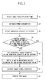
- FIG. 2 is a flowchart illustrating a driving sequence of the display device according to an embodiment of the present invention.
- FIG. 1 is a schematic view of a display device according to an embodiment of the present invention.
- the display device includes a storage element 100, a selection circuit 200 configured to select all or part of one, some or all of the images stored in the storage element 100 according to a request of a user, a battery 400, a controller 300 including a first detection circuit 320 configured to detect and/or analyze the image(s) selected by the selection circuit and estimate power consumption for displaying the image(s) selected by the selection circuit 200 and a control circuit 310 configured to control an image signal of the image(s) according to the estimated power consumption and a remaining capacity of the battery, a display panel 500 configured to display the image(s) in response to the image signal controlled by the controller 300, and a second detection circuit 410 for detecting the remaining capacity of the battery 400 and outputting the result to the controller 300.
- a controller 300 including a first detection circuit 320 configured to detect and/or analyze the image(s) selected by the selection circuit and estimate power consumption for displaying the image(s) selected by the selection circuit 200 and a control circuit 310 configured to control an image signal of the image(s) according
- the controller 300 includes a comparison circuit 330 configured to compare outputs of the first and second detection circuits 320 and 410, and a brightness setting circuit 340 configured to output red, green and blue conversion signals according to the output of the comparison circuit 330.
- the brightness setting circuit 340 includes a setting circuit 341 for outputting a first setting signal for setting a brightness of the image(s) selected by the selection circuit 200 in response to the output of the comparison circuit 330, a red conversion circuit (RCR) 342R for outputting a red conversion signal for setting red gradation of the image(s) in response to the first setting signal, a green conversion circuit (GCR) 342G for outputting a green conversion signal for setting green gradation of the image(s) in response to the first setting signal, and a blue conversion circuit (BCR) 342B for outputting a blue conversion signal for setting blue gradation of the image(s) in response to the first setting signal.
- RCR red conversion circuit
- GCR green conversion circuit
- BCR blue conversion circuit
- the display panel 500 may be an organic light emitting diode (OLED) display device including a plurality of red, green and blue organic light emitting diodes (OLEDs).
- OLED organic light emitting diode
- FIG. 2 is a flowchart illustrating a driving sequence of the display device of FIG. 1 .
- the selection circuit 200 selects all or a part of the image (or selects some or all of the images) stored in the storage element 100 according to the user's request (S1), and an image signal of the image is input to the controller 300.
- the first detection circuit 320 analyzes and/or detects the image signal of the image to estimate power consumption taken to display the image (S2).
- the signal for the remaining capacity of the battery 400 is received from the second detection circuit 410 for detecting the remaining capacity of the battery 400 (S3).
- the first detection circuit 320 estimates power consumption of the selected image for a short period of time by extracting a specific order of image from each frame of the selected image, and estimates the required currents from the extracted images.
- a brightness of a red pixel is estimated by the following equation (1) using a white brightness W B detected from each image, and brightnesses of green and blue pixels are estimated by the same (or substantially the same) method.
- R L R LR ⁇ W B ⁇ 1 R A ⁇ 1 T ⁇ 3
- R L is a brightness of a red pixel
- R LR is a brightness ratio of the red pixel
- R A is an aperture ratio of the red pixel
- T is a transmittance of the display device.
- the comparison circuit 330 compares the outputs of the first and second detection circuits 320 and 410, and then the controller 300 determines if the remaining capacity of the battery 400 is equal to or higher than the estimated power consumption (S4).
- the setting circuit 341 When the estimated power consumption is higher than the remaining capacity of the battery 400, in order to completely display the selected image using the remaining capacity of the battery 400, in the brightness setting circuit 340, the setting circuit 341 outputs the first setting signal to set the brightness of the image (S5), and the red, green and blue conversion circuits 342R, 342G and 342B generate red, green and blue conversion signals to set the red, green and blue gradations of the image in response to the first setting signal, respectively (S6).
- the first setting signal indicates a set brightness of white W SL of each image detected by the following equation (3)
- the red, green and blue conversion circuits 342R, 342G and 342B output a difference between the red, green and blue brightness according to the set brightness of white determined by the following equation (3) and the red, green and blue brightnesses of the selected image as the red, green and blue conversion signals using the equations (1) and (2).
- W SL C 2 C 1 ⁇ W B
- C 1 is the estimated power consumption estimated by the first detection circuit
- C 2 is the remaining capacity of the battery detected by the second detection circuit.
- the display panel is an OLED display device including red, green and blue OLEDs
- red, green and blue OLEDs as different power consumptions are respectively applied to the red, green and blue OLEDs to obtain an equal brightness
- the power applied to the red, green and blue pixels is reduced according to a ratio of the estimated power consumption and the remaining capacity of the battery to reduce the brightness of the selected image.
- a white balance of the image displayed on the display panel is changed (not properly balanced), resulting in poor displaying quality of the image.
- the white brightness of the image is reset according to the ratio of the estimated power consumption and the remaining capacity of the battery, and the power applied to the red, green and blue pixels is reduced according to the reset white brightness; the white balance of the image displayed on the display panel is properly balanced and the display quality of the image displayed on the display panel 500 is not degraded due to the resetting of the white balance.
- control circuit 310 converts an image signal received from the selected circuit 200 in response to the received red, green and blue conversion signals (S7), and then outputs the image signal to the display panel 500, so as to display the image having the brightness set by the brightness setting circuit 340.
- the display device converts red, green and blue gradations of the selected image and thus controls a brightness of the image in order to display the image without interruption and change in display.
- a display device estimates power consumption to complete the display of the image for the certain period of time, detects a remaining capacity of a battery, and reduces a brightness of the image according to the remaining capacity of the battery when the estimated power consumption exceeds the remaining capacity of the battery.
- the user-selected image can be completely displayed for the certain period of time without interruption.
Landscapes
- Engineering & Computer Science (AREA)
- Physics & Mathematics (AREA)
- General Physics & Mathematics (AREA)
- Theoretical Computer Science (AREA)
- Computer Hardware Design (AREA)
- General Engineering & Computer Science (AREA)
- Electroluminescent Light Sources (AREA)
- Control Of El Displays (AREA)
- Control Of Indicators Other Than Cathode Ray Tubes (AREA)
- Liquid Crystal Display Device Control (AREA)
- Liquid Crystal (AREA)
Abstract
Description
- The present invention relates to a display device for displaying an image utilizing a battery and a method of driving the same, and more particularly, to a display device capable of displaying a user-selected image for a desired period of time without interruption of the image even when power consumption exceeds a remaining capacity of the battery, and a method of driving the same.
- Since flat panel display devices are lightweight and thin, they are used as substitutes for cathode-ray tube display devices. Examples of the flat panel display device include liquid crystal display (LCD) devices, and organic light emitting diode (OLED) display devices. Among these, the OLED display devices have high brightness and a wide viewing angle. In addition, since the OLED display devices do not need a back light, the OLED display devices can be implemented as ultra-thin display devices.
- The flat panel display device has been generally applied to compact and lightweight hand-held electric/electronic devices such as cellular phones, notebook computers and camcorders, and these electric/electronic devices include a battery capable of being operated in places in which there is no power source.
- However, the display device displaying an image utilizing a battery such as the hand-held electric/electronic device may interrupt the display of a user-selected image stored in a storage element for a certain period of time when a remaining capacity of the battery is less than power needed to display the image for the certain period of time.
- Aspects of the present invention are directed toward a display device capable of displaying a user-selected image for a period of time without interruption regardless of a remaining capacity of a battery and a method of driving the same.
- According to a first aspect of the present invention, a display device includes: a storage element; a selection circuit configured to select an image stored in the storage element according to a user request; a first detection circuit configured to estimate power consumption for displaying the selected image; a second detection circuit configured to detect a remaining capacity of a battery; a comparison circuit configured to compare outputs of the first and second detection circuits and to provide a comparison output in accordance with the compared outputs of the first and second circuits; a brightness setting circuit configured to output red, green and blue conversion signals to set a brightness of the selected image according to the comparison output of the comparison circuit; a control circuit configured to change a brightness of an image signal of the selected image in accordance with the red, green and blue conversion signals and to provide a control output; and a display panel configured to display the selected image in accordance with the control output of the control circuit.
- In one embodiment, the brightness setting circuit includes a setting circuit for outputting a first setting signal to control the brightness of the selected image according to the comparison output of the comparison circuit, a red conversion circuit for outputting the red conversion signal to set red gradation of the selected image in response to the first setting signal, a green conversion circuit for outputting the green conversion signal to set green gradation of the image in response to the first setting signal, and a blue conversion circuit for outputting the blue conversion signal to set blue gradation of the image in response to the first setting signal.
- According to another aspect of the present invention, a method of driving a display device includes: selecting an image stored in a storage element according to a user request; estimating power consumption utilized to display the selected image; detecting a remaining capacity of a battery; comparing the estimated power consumption with the remaining capacity of the battery; generating a first setting signal to set a brightness of the selected image according to the remaining capacity of the battery when the estimated power consumption exceeds the remaining capacity of the battery; generating red, green and blue conversion signals to control red, green and blue gradations of the selected image in response to the first setting signal; converting an image signal of the selected image in response to the red, green and blue conversion signals; and displaying the selected image in response to the converted image signal.
- Additional aspects and/or embodiments of the invention will be set forth in part in the description which follows, but the present invention is not limited to the disclosed aspects and/or embodiments.
- The accompanying drawings, together with the specification, illustrate embodiments of the present invention, and, together with the description, serve to explain the principles of the present invention.
-
FIG. 1 is a schematic view of a display device according to an embodiment of the present invention; and -
FIG. 2 is a flowchart illustrating a driving sequence of the display device according to an embodiment of the present invention. - In the following detailed description, only certain embodiments of the present invention are shown and described, by way of illustration. As those skilled in the art would recognize, the invention may be embodied in many different forms and should not be construed as being limited to the embodiments set forth herein. Also, in the context of the present application, when an element is referred to as being "on" another element, it can be directly on the another element or be indirectly on the another element with one or more intervening elements interposed therebetween. Like reference numerals designate like elements throughout the specification.
-
FIG. 1 is a schematic view of a display device according to an embodiment of the present invention. - Referring to
FIG. 1 , the display device includes astorage element 100, aselection circuit 200 configured to select all or part of one, some or all of the images stored in thestorage element 100 according to a request of a user, abattery 400, acontroller 300 including afirst detection circuit 320 configured to detect and/or analyze the image(s) selected by the selection circuit and estimate power consumption for displaying the image(s) selected by theselection circuit 200 and acontrol circuit 310 configured to control an image signal of the image(s) according to the estimated power consumption and a remaining capacity of the battery, adisplay panel 500 configured to display the image(s) in response to the image signal controlled by thecontroller 300, and asecond detection circuit 410 for detecting the remaining capacity of thebattery 400 and outputting the result to thecontroller 300. - Here, the
controller 300 includes acomparison circuit 330 configured to compare outputs of the first andsecond detection circuits brightness setting circuit 340 configured to output red, green and blue conversion signals according to the output of thecomparison circuit 330. Thebrightness setting circuit 340 includes asetting circuit 341 for outputting a first setting signal for setting a brightness of the image(s) selected by theselection circuit 200 in response to the output of thecomparison circuit 330, a red conversion circuit (RCR) 342R for outputting a red conversion signal for setting red gradation of the image(s) in response to the first setting signal, a green conversion circuit (GCR) 342G for outputting a green conversion signal for setting green gradation of the image(s) in response to the first setting signal, and a blue conversion circuit (BCR) 342B for outputting a blue conversion signal for setting blue gradation of the image(s) in response to the first setting signal. - The
display panel 500 may be an organic light emitting diode (OLED) display device including a plurality of red, green and blue organic light emitting diodes (OLEDs). -
FIG. 2 is a flowchart illustrating a driving sequence of the display device ofFIG. 1 . - Referring to
FIGS. 1 and2 , when a user's request for a specific image (or images) to be displayed for a certain period of time is input, theselection circuit 200 selects all or a part of the image (or selects some or all of the images) stored in thestorage element 100 according to the user's request (S1), and an image signal of the image is input to thecontroller 300. - Subsequently, in the
controller 300, thefirst detection circuit 320 analyzes and/or detects the image signal of the image to estimate power consumption taken to display the image (S2). Next, the signal for the remaining capacity of thebattery 400 is received from thesecond detection circuit 410 for detecting the remaining capacity of the battery 400 (S3). - Here, the
first detection circuit 320 estimates power consumption of the selected image for a short period of time by extracting a specific order of image from each frame of the selected image, and estimates the required currents from the extracted images. - More specifically, a brightness of a red pixel is estimated by the following equation (1) using a white brightness WB detected from each image, and brightnesses of green and blue pixels are estimated by the same (or substantially the same) method.

Herein, RL is a brightness of a red pixel, RLR is a brightness ratio of the red pixel, RA is an aperture ratio of the red pixel, and T is a transmittance of the display device. - Next, power consumptions of the red pixels from each image are estimated using the following equation (2), to thereby estimate power consumption from the image. Green and blue pixels are estimated using the same (or substantially the same) method.

Herein, RC is the estimated power consumption of the red pixel, RE is emission efficiency of the red pixel, and Rn is the number of the red pixels of each image. - Subsequently, the
comparison circuit 330 compares the outputs of the first andsecond detection circuits controller 300 determines if the remaining capacity of thebattery 400 is equal to or higher than the estimated power consumption (S4). - When the estimated power consumption is higher than the remaining capacity of the
battery 400, in order to completely display the selected image using the remaining capacity of thebattery 400, in thebrightness setting circuit 340, thesetting circuit 341 outputs the first setting signal to set the brightness of the image (S5), and the red, green andblue conversion circuits - Here, the first setting signal indicates a set brightness of white WSL of each image detected by the following equation (3), and the red, green and
blue conversion circuits 
Herein, C1 is the estimated power consumption estimated by the first detection circuit, and C2 is the remaining capacity of the battery detected by the second detection circuit. - When the display panel is an OLED display device including red, green and blue OLEDs, as different power consumptions are respectively applied to the red, green and blue OLEDs to obtain an equal brightness, the power applied to the red, green and blue pixels is reduced according to a ratio of the estimated power consumption and the remaining capacity of the battery to reduce the brightness of the selected image. Here, a white balance of the image displayed on the display panel is changed (not properly balanced), resulting in poor displaying quality of the image.
- Thus, as described in the embodiment of the present invention, when the white brightness of the image is reset according to the ratio of the estimated power consumption and the remaining capacity of the battery, and the power applied to the red, green and blue pixels is reduced according to the reset white brightness; the white balance of the image displayed on the display panel is properly balanced and the display quality of the image displayed on the
display panel 500 is not degraded due to the resetting of the white balance. - Subsequently, the
control circuit 310 converts an image signal received from theselected circuit 200 in response to the received red, green and blue conversion signals (S7), and then outputs the image signal to thedisplay panel 500, so as to display the image having the brightness set by thebrightness setting circuit 340. - As a result, when the estimated power consumption utilized to display the image requested by the user exceeds the remaining capacity of the battery, that is, the remaining capacity of the battery is not sufficient, the display device according to the embodiment of the present invention converts red, green and blue gradations of the selected image and thus controls a brightness of the image in order to display the image without interruption and change in display.
- According to the present invention, to display a specific image selected by a user for a certain period of time, a display device estimates power consumption to complete the display of the image for the certain period of time, detects a remaining capacity of a battery, and reduces a brightness of the image according to the remaining capacity of the battery when the estimated power consumption exceeds the remaining capacity of the battery. Thus, the user-selected image can be completely displayed for the certain period of time without interruption.
- While the present invention has been described in connection with certain embodiments, it is to be understood that the invention is not limited to the disclosed embodiments, but, on the contrary, is intended to cover various modifications and equivalent arrangements included within the scope of the appended claims, and equivalents thereof.
Claims (14)
- A display device, comprising:a storage element;a selection circuit configured to select an image stored in the storage element according to a user request;a first detection circuit configured to estimate power consumption for displaying the selected image at a predetermined brightness level;a second detection circuit configured to detect a remaining capacity of a battery;a comparison circuit configured to compare outputs of the first and second detection circuits and to provide a comparison output in accordance with the compared outputs of the first and second circuits;a brightness setting circuit configured to output red, green and blue conversion signals to set a brightness of the selected image according to the comparison output of the comparison circuit;a control circuit configured to change a brightness of an image signal of the selected image in accordance with the red, green and blue conversion signals and to provide a control output; anda display panel configured to display the selected image in accordance with the control output of the control circuit.
- A display device according to claim 1, wherein the first detection circuit is configured to estimate the power consumption of the selected image by utilizing the following equations (1) and (2):


wherein, RL is a brightness of a red, green or blue pixel, RLR is a brightness ratio of the red, green or blue pixel, RA is an aperture ratio of the red, green or blue pixel, T is a transmittance of the display device, RC is the estimated power consumption of the red, green or blue pixel, RE is an emission efficiency of the red, green or blue pixel, and Rn is the number of the red, green or blue pixels of the selected image. - A display device according to claim 1 or 2, wherein the brightness setting circuit comprises a setting circuit for outputting a first setting signal to control the brightness of the selected image according to the comparison output of the comparison circuit, a red conversion circuit for outputting the red conversion signal to set red gradation of the selected image in response to the first setting signal, a green conversion circuit for outputting the green conversion signal to set green gradation of the image in response to the first setting signal, and a blue conversion circuit for outputting the blue conversion signal to set blue gradation of the image in response to the first setting signal.
- A display device according to claim 3, wherein the setting circuit generates the first setting signal by utilizing the following equation (3):

wherein, WSL is the first setting signal, WB is a white brightness of the selected image, C1 is the estimated power consumption estimated by the first detection circuit, and C2 is the remaining capacity of the battery detected by the second detection circuit. - A display device according to any preceding claim, wherein the display panel is an organic light emitting diode (OLED) display device comprising a plurality of OLEDs.
- A method of driving a display device, comprising:selecting an image stored in a storage element according to a user request;estimating the power consumption required to display the selected image at a predetermined brightness level;detecting the remaining capacity of a battery;comparing the estimated power consumption with the remaining capacity of the battery;generating a first setting signal to set a brightness of the selected image according to the remaining capacity of the battery when the estimated power consumption exceeds the remaining capacity of the battery;generating red, green and blue conversion signals to control red, green and blue gradations of the selected image in response to the first setting signal;converting an image signal of the selected image in response to the red, green and blue conversion signals; anddisplaying the selected image in response to the converted image signal.
- A method according to claim 6, wherein the estimated power consumption is estimated by utilizing the following equations (1) and (2):


wherein, RL is a brightness of a red, green or blue pixel, RLR is a brightness ratio of the red, green or blue pixel, RA is an aperture ratio of the red, green or blue pixel, T is a transmittance of the display device, RC is the estimated power consumption of the red, green or blue pixel, RE is an emission efficiency of the red pixel, and Rn is the number of the red, green or blue pixels of the selected image. - A method according to claim 6 or 7, wherein the first setting signal is generated using the following equation (3):

wherein, WSL is the first setting signal, WB is a white brightness of the selected image, C1 is the estimated power consumption detected by a first detection circuit, and C2 is the remaining capacity of the battery detected by a second detection circuit. - A method according to claim 6, 7 or 8 wherein the image in response to the converted image signal is displayed on an OLED display device comprising a plurality of OLEDs.
- A display device, comprising:a storage element;a selection circuit configured to select an image stored in the storage element according to a user request;a battery;a first detection circuit configured to detect a remaining capacity of the battery;a controller; anda display panel coupled to the battery via the controller and configured to display the selected image in accordance with a control output of the controller, the controller comprising:a second detection circuit configured to estimate power consumption for displaying the selected image;a comparison circuit configured to compare outputs of the first and second detection circuits and to provide a comparison output in accordance with the compared outputs of the first and second circuits;a brightness setting circuit configured to output red, green and blue conversion signals to set a brightness of the selected image according to the comparison output of the comparison circuit; anda control circuit configured to change a brightness of an image signal of the selected image in accordance with the red, green and blue conversion signals and to provide the control output.
- The display device according to claim 10, wherein the second detection circuit is configured to estimate the power consumption of the selected image by utilizing the following equations (1) and (2):


wherein, RL is a brightness of a red, green or blue pixel, RLR is a brightness ratio of the red, green or blue pixel, RA is an aperture ratio of the red, green or blue pixel, T is a transmittance of the display device, RC is the estimated power consumption of the red, green or blue pixel, RE is an emission efficiency of the red, green or blue pixel, and Rn is the number of the red, green or blue pixels of the selected image. - The display device according to claim 10, wherein the brightness setting circuit comprises a setting circuit for outputting a first setting signal to control the brightness of the selected image according to the comparison output of the comparison circuit, a red conversion circuit for outputting the red conversion signal to set red gradation of the selected image in response to the first setting signal, a green conversion circuit for outputting the green conversion signal to set green gradation of the image in response to the first setting signal, and a blue conversion circuit for outputting the blue conversion signal to set blue gradation of the image in response to the first setting signal.
- The display device according to claim 12, wherein the setting circuit generates the first setting signal by utilizing the following equation (3):

wherein, WSL is the first setting signal, WB is a white brightness of the selected image, C1 is the estimated power consumption estimated by the first detection circuit, and C2 is the remaining capacity of the battery detected by the second detection circuit. - The display device according to claim 10, wherein the display panel is an organic light emitting diode (OLED) display device comprising a plurality of OLEDs.
Applications Claiming Priority (1)
| Application Number | Priority Date | Filing Date | Title |
|---|---|---|---|
| KR1020090001580A KR101023130B1 (en) | 2009-01-08 | 2009-01-08 | Display device and driving method thereof |
Publications (2)
| Publication Number | Publication Date |
|---|---|
| EP2207157A2 true EP2207157A2 (en) | 2010-07-14 |
| EP2207157A3 EP2207157A3 (en) | 2010-07-21 |
Family
ID=42111606
Family Applications (1)
| Application Number | Title | Priority Date | Filing Date |
|---|---|---|---|
| EP10250025A Withdrawn EP2207157A3 (en) | 2009-01-08 | 2010-01-08 | Display device and method for driving the same |
Country Status (5)
| Country | Link |
|---|---|
| US (1) | US8421814B2 (en) |
| EP (1) | EP2207157A3 (en) |
| JP (1) | JP5362452B2 (en) |
| KR (1) | KR101023130B1 (en) |
| CN (1) | CN101777333B (en) |
Families Citing this family (11)
| Publication number | Priority date | Publication date | Assignee | Title |
|---|---|---|---|---|
| JP5772046B2 (en) * | 2010-05-24 | 2015-09-02 | 株式会社リコー | Image processing apparatus, image processing apparatus control method, and program |
| JP5455857B2 (en) * | 2010-09-28 | 2014-03-26 | 富士フイルム株式会社 | Radiation image capturing apparatus, radiation image capturing method, and radiation image capturing program |
| JP5747610B2 (en) * | 2011-03-30 | 2015-07-15 | ソニー株式会社 | CHARGE CONTROL DEVICE, CHARGE CONTROL METHOD, PROGRAM, AND SYSTEM |
| KR101950823B1 (en) * | 2011-11-14 | 2019-02-22 | 엘지디스플레이 주식회사 | Flat panel display and method for driving the same |
| JP5682585B2 (en) * | 2012-03-16 | 2015-03-11 | 株式会社リコー | Information processing apparatus, information processing system, and information processing method |
| KR101851577B1 (en) | 2012-09-17 | 2018-04-24 | 삼성전자주식회사 | Methods and devices for controlling operations of organic light-emitting diode display |
| US20140160148A1 (en) * | 2012-12-10 | 2014-06-12 | Andrew J. Barkett | Context-Based Image Customization |
| CN104424901B (en) * | 2013-09-11 | 2019-01-04 | 中兴通讯股份有限公司 | A kind of method and device that screen intensity is adjusted |
| JP6389729B2 (en) * | 2013-10-22 | 2018-09-12 | 株式会社ジャパンディスプレイ | Display device and color conversion method |
| US10847118B2 (en) * | 2017-05-12 | 2020-11-24 | Apple Inc. | Electronic devices with tone mapping engines |
| US11011102B2 (en) * | 2017-09-21 | 2021-05-18 | Canon Kabushiki Kaisha | Display apparatus and control method therefor |
Family Cites Families (15)
| Publication number | Priority date | Publication date | Assignee | Title |
|---|---|---|---|---|
| JP4443660B2 (en) | 1999-02-26 | 2010-03-31 | パナソニック株式会社 | Information processing device |
| JP2004012600A (en) * | 2002-06-04 | 2004-01-15 | Canon Inc | Organic EL liquid crystal device |
| KR100455165B1 (en) | 2002-10-11 | 2004-11-06 | 엘지전자 주식회사 | Lighting device control method for mobile terminal |
| JP2004157526A (en) * | 2002-10-15 | 2004-06-03 | Nec Electronics Corp | Controller-driver, display device, and display method |
| US7184067B2 (en) * | 2003-03-13 | 2007-02-27 | Eastman Kodak Company | Color OLED display system |
| CN1820295A (en) * | 2003-05-07 | 2006-08-16 | 东芝松下显示技术有限公司 | El display and its driving method |
| CN1864189B (en) * | 2003-08-05 | 2010-10-06 | 东芝松下显示技术有限公司 | Driving circuit and driving method for self-luminous display device |
| KR100643377B1 (en) * | 2004-01-17 | 2006-11-10 | 삼성전자주식회사 | Portable Computers and Control Methods |
| JP2005345678A (en) | 2004-06-02 | 2005-12-15 | Mitsubishi Electric Corp | Portable display device |
| JP3997358B2 (en) * | 2004-07-15 | 2007-10-24 | 船井電機株式会社 | Video playback device |
| JP4448403B2 (en) * | 2004-08-16 | 2010-04-07 | 富士通株式会社 | Power level measuring apparatus and mobile station |
| JP2007156130A (en) * | 2005-12-06 | 2007-06-21 | Canon Inc | Organic electroluminescence display device |
| US7603048B2 (en) * | 2007-01-30 | 2009-10-13 | Kabushiki Kaisha Toshiba | Image forming apparatus and control method thereof |
| JP2008203481A (en) | 2007-02-20 | 2008-09-04 | Seiko Instruments Inc | Tuning device |
| JP2008252185A (en) * | 2007-03-29 | 2008-10-16 | Kyocera Corp | Portable electronic devices |
-
2009
- 2009-01-08 KR KR1020090001580A patent/KR101023130B1/en not_active Expired - Fee Related
- 2009-06-12 JP JP2009140962A patent/JP5362452B2/en active Active
- 2009-12-22 US US12/645,096 patent/US8421814B2/en active Active
-
2010
- 2010-01-08 CN CN2010100029069A patent/CN101777333B/en active Active
- 2010-01-08 EP EP10250025A patent/EP2207157A3/en not_active Withdrawn
Non-Patent Citations (1)
| Title |
|---|
| None |
Also Published As
| Publication number | Publication date |
|---|---|
| KR101023130B1 (en) | 2011-03-24 |
| US20100171751A1 (en) | 2010-07-08 |
| CN101777333B (en) | 2013-12-25 |
| EP2207157A3 (en) | 2010-07-21 |
| CN101777333A (en) | 2010-07-14 |
| JP2010160469A (en) | 2010-07-22 |
| US8421814B2 (en) | 2013-04-16 |
| JP5362452B2 (en) | 2013-12-11 |
| KR20100082204A (en) | 2010-07-16 |
Similar Documents
| Publication | Publication Date | Title |
|---|---|---|
| EP2207157A2 (en) | Display device and method for driving the same | |
| CN111798777B (en) | Signal processing apparatus and image display device including the same | |
| US8059069B2 (en) | Organic light emitting diode display device and driving method thereof | |
| US9418591B2 (en) | Timing controller, driving method thereof, and display device using the same | |
| US7982693B2 (en) | OLED display apparatus | |
| US8508442B2 (en) | Organic light emitting display device and driving method thereof | |
| US8411021B2 (en) | Display control apparatus and display control method for adjusting display luminance according to ambient brightness | |
| KR102196912B1 (en) | display device and driving method thereof | |
| US8466857B2 (en) | Image display apparatus for adjusting luminance of a display based on remaining battery level and estimated power consumption | |
| KR101484447B1 (en) | Character highlighting control apparatus, display apparatus, highlighting display control method, and recording medium | |
| KR20110006112A (en) | Apparatus and method for controlling backlight of display panel in camera system | |
| US11621301B2 (en) | Display device and signal processing device | |
| US20150364081A1 (en) | Image processing apparatus, image processing method, display device, computer program and computer-readable medium | |
| JP5069069B2 (en) | Organic electroluminescent display device and driving method thereof | |
| US20120105517A1 (en) | Method for driving active matrix organic light emitting diode display panel | |
| CN101236728A (en) | Method and apparatus for controlling backlight in display device | |
| US20060256054A1 (en) | Display device and apparatus and method for driving the same | |
| US20150348500A1 (en) | Signal conversion method for display image | |
| US7834885B2 (en) | Display apparatus and image processing method thereof | |
| US10685596B2 (en) | Display apparatus and operating method thereof | |
| US12531014B2 (en) | Signal processing device, signal processing method, and display device | |
| US20150181188A1 (en) | Display device, electronic apparatus, and method for driving display device | |
| KR20180025050A (en) | Organic light emitting device and electric apparatus comprising the same | |
| KR100667079B1 (en) | Auto Brightness Organic Electroluminescent Display | |
| US20110199396A1 (en) | Method and apparatus for displaying image for self-luminescence display |
Legal Events
| Date | Code | Title | Description |
|---|---|---|---|
| PUAI | Public reference made under article 153(3) epc to a published international application that has entered the european phase |
Free format text: ORIGINAL CODE: 0009012 |
|
| PUAL | Search report despatched |
Free format text: ORIGINAL CODE: 0009013 |
|
| 17P | Request for examination filed |
Effective date: 20100114 |
|
| AK | Designated contracting states |
Kind code of ref document: A2 Designated state(s): AT BE BG CH CY CZ DE DK EE ES FI FR GB GR HR HU IE IS IT LI LT LU LV MC MK MT NL NO PL PT RO SE SI SK SM TR |
|
| AX | Request for extension of the european patent |
Extension state: AL BA RS |
|
| AK | Designated contracting states |
Kind code of ref document: A3 Designated state(s): AT BE BG CH CY CZ DE DK EE ES FI FR GB GR HR HU IE IS IT LI LT LU LV MC MK MT NL NO PL PT RO SE SI SK SM TR |
|
| AX | Request for extension of the european patent |
Extension state: AL BA RS |
|
| RAP1 | Party data changed (applicant data changed or rights of an application transferred) |
Owner name: SAMSUNG DISPLAY CO., LTD. |
|
| 17Q | First examination report despatched |
Effective date: 20130903 |
|
| RAP1 | Party data changed (applicant data changed or rights of an application transferred) |
Owner name: SAMSUNG DISPLAY CO., LTD. |
|
| GRAP | Despatch of communication of intention to grant a patent |
Free format text: ORIGINAL CODE: EPIDOSNIGR1 |
|
| INTG | Intention to grant announced |
Effective date: 20170405 |
|
| STAA | Information on the status of an ep patent application or granted ep patent |
Free format text: STATUS: THE APPLICATION IS DEEMED TO BE WITHDRAWN |
|
| 18D | Application deemed to be withdrawn |
Effective date: 20170817 |