EP2206997A1 - Control joints in refactory lining systems and methods - Google Patents
Control joints in refactory lining systems and methods Download PDFInfo
- Publication number
- EP2206997A1 EP2206997A1 EP09180257A EP09180257A EP2206997A1 EP 2206997 A1 EP2206997 A1 EP 2206997A1 EP 09180257 A EP09180257 A EP 09180257A EP 09180257 A EP09180257 A EP 09180257A EP 2206997 A1 EP2206997 A1 EP 2206997A1
- Authority
- EP
- European Patent Office
- Prior art keywords
- layer
- outer layer
- control joint
- segments
- refractory
- Prior art date
- Legal status (The legal status is an assumption and is not a legal conclusion. Google has not performed a legal analysis and makes no representation as to the accuracy of the status listed.)
- Granted
Links
Images



Classifications
-
- F—MECHANICAL ENGINEERING; LIGHTING; HEATING; WEAPONS; BLASTING
- F27—FURNACES; KILNS; OVENS; RETORTS
- F27D—DETAILS OR ACCESSORIES OF FURNACES, KILNS, OVENS OR RETORTS, IN SO FAR AS THEY ARE OF KINDS OCCURRING IN MORE THAN ONE KIND OF FURNACE
- F27D1/00—Casings; Linings; Walls; Roofs
- F27D1/0003—Linings or walls
- F27D1/0023—Linings or walls comprising expansion joints or means to restrain expansion due to thermic flows
-
- C—CHEMISTRY; METALLURGY
- C10—PETROLEUM, GAS OR COKE INDUSTRIES; TECHNICAL GASES CONTAINING CARBON MONOXIDE; FUELS; LUBRICANTS; PEAT
- C10J—PRODUCTION OF PRODUCER GAS, WATER-GAS, SYNTHESIS GAS FROM SOLID CARBONACEOUS MATERIAL, OR MIXTURES CONTAINING THESE GASES; CARBURETTING AIR OR OTHER GASES
- C10J3/00—Production of combustible gases containing carbon monoxide from solid carbonaceous fuels
- C10J3/72—Other features
- C10J3/74—Construction of shells or jackets
-
- F—MECHANICAL ENGINEERING; LIGHTING; HEATING; WEAPONS; BLASTING
- F27—FURNACES; KILNS; OVENS; RETORTS
- F27D—DETAILS OR ACCESSORIES OF FURNACES, KILNS, OVENS OR RETORTS, IN SO FAR AS THEY ARE OF KINDS OCCURRING IN MORE THAN ONE KIND OF FURNACE
- F27D1/00—Casings; Linings; Walls; Roofs
- F27D1/04—Casings; Linings; Walls; Roofs characterised by the form, e.g. shape of the bricks or blocks used
- F27D1/045—Bricks for lining cylindrical bodies, e.g. skids, tubes
-
- C—CHEMISTRY; METALLURGY
- C10—PETROLEUM, GAS OR COKE INDUSTRIES; TECHNICAL GASES CONTAINING CARBON MONOXIDE; FUELS; LUBRICANTS; PEAT
- C10J—PRODUCTION OF PRODUCER GAS, WATER-GAS, SYNTHESIS GAS FROM SOLID CARBONACEOUS MATERIAL, OR MIXTURES CONTAINING THESE GASES; CARBURETTING AIR OR OTHER GASES
- C10J2200/00—Details of gasification apparatus
- C10J2200/09—Mechanical details of gasifiers not otherwise provided for, e.g. sealing means
-
- C—CHEMISTRY; METALLURGY
- C10—PETROLEUM, GAS OR COKE INDUSTRIES; TECHNICAL GASES CONTAINING CARBON MONOXIDE; FUELS; LUBRICANTS; PEAT
- C10J—PRODUCTION OF PRODUCER GAS, WATER-GAS, SYNTHESIS GAS FROM SOLID CARBONACEOUS MATERIAL, OR MIXTURES CONTAINING THESE GASES; CARBURETTING AIR OR OTHER GASES
- C10J2300/00—Details of gasification processes
- C10J2300/18—Details of the gasification process, e.g. loops, autothermal operation
- C10J2300/1846—Partial oxidation, i.e. injection of air or oxygen only
Definitions
- the subject matter disclosed herein relates generally to refractory vessel design.
- a gasifier is a type of reactor used for partial oxidation of a fossil fuel, such as coal or a heavy fuel oil, to produce energy. Temperatures inside a gasifier vessel may reach over 700°C during operation.
- a gasifier vessel may be insulated by a multi-layer refractory lining. The vessel and lining may comprise concentric cylindrical layers. During gasifier operation, high temperatures may cause the layers to expand outwardly, or radially. Each layer may expand differently, according to the temperature and the coefficient of thermal expansion (COE) of the particular layer.
- COE coefficient of thermal expansion
- the inner layers are at a higher temperature, and may have a higher COE, than the outer layers. Inner layers may push against the outer layers due to expansion that occurs during operation of the gasifier, as the outer layers may expand less than the inner layer.
- Gas bypass may cause high skin temperatures, or hot spots, in the outer shell of the gasifier. Forced shutdown of the gasifier may be necessary if hot spots become severe, leading to costly maintenance and loss of productivity.
- a refractory lining system comprises an inner refractory layer; and an outer layer located outside of the inner refractory layer, the outer layer comprising: a plurality of layer segments; and at least one control joint located between the plurality of layer segments, the at least one control joint configured to allow expansion and contraction in the outer layer.
- a segment of an outer layer of a refractory lining comprises an edge shaped corresponding to a control joint configured to allow expansion and contraction in the outer layer.
- a method of making an outer layer of a refractory lining comprises forming a plurality of segments of the outer layer, each segment comprising an edge shaped corresponding to a control joint configured to allow expansion and contraction in the outer layer; and assembling the plurality of segments to form the outer layer of the refractory lining.
- a gasifier vessel comprises a plurality of refractory lining layers to insulate the high temperature at which the gasification process occurs. If a lining layer cracks, gas from the gasification process may pass through the lining to the outer shell of the gasifier, resulting in hot spots on the outer shell and possible damage to the gasifier.
- a primary cause of hot spots in the outer shell of a gasifier may be prevented by providing a plurality of control joints in an outer layer of the refractory lining.
- Control joints also referred to a non-continuous joints, slip joints or shiplaps, are a mechanical construction that allow expansion and contraction in a structure. The control joints mitigate radial expansion differences between the various layers of the gasifier lining.
- a slip plane within the control joint prevents formation of a continuous gas path during opening of the joint.
- the control joint may slide open by a small margin without significant gas bypass, reducing the stress and failure modes of the castable layer.
- a reduction in stress in an outer layer is accompanied by a proportional decrease in the amount of opposing stress in the inner layer, reducing the rate of failure and long term deformation or creep in the gasifier lining. Reliability of the gasifier is increased, resulting in reduced operating costs due to decreased unplanned outages.
- Incorporation of control joints into an outer layer does not entail significant increase in installation schedules or material costs, as materials and installation techniques already in use may be used to implement non-continuous joints in the outer layer.
- a gasifier 100 may include a plurality of refractory lining layers, including but not limited to an inner refractory layer 101, an outer thermal layer 102, and an outer shell 103. While three layers are shown in the embodiment of a gasifier shown in FIG. 1 , a gasifier may include any appropriate number of lining layers.
- Outer thermal layer 102 may comprise a monolithic refractory, for example, concrete, in some embodiments.
- the inner refractory layer 101 expands radially during operation of the gasifier, and pushes against outer thermal layer 102. This may cause outer thermal layer 102 to crack due various factors, including initial shrinkage, relatively low tensile strength, and lesser radial expansion. The cracking may be substantial, extending from the back of the refractory layer 101 directly to the outer shell 103. Such cracking may result in gas bypass through outer thermal layer 102, causing hot spots in outer shell 103.
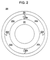
- FIG. 2 shows a top cross section of an embodiment of a refractory lining 200 comprising control joints.
- the refractory lining 200 comprises outer shell 204, inner refractory layer 201, and an outer thermal layer that comprises segments 202a, 202b, 202c, and 202d joined by control joints 203a, 203b, 203c, and 203d.
- the outer thermal layer may be divided into a plurality of segments; the four segments 202a-d shown in the embodiment of FIG. 2 are for illustrative purposes only.
- Control joints 203a-d prevent cracking in the outer thermal layer by opening under pressure, creating space between segments 202a-d.
- the control joints 203a-d are shaped in a manner that opening of control joints 203a-d does not provide a continuous path for gas bypass from the refractory layer 201 to the outer shell 203.
- Control joints 203a-d thereby relieve the stress in segments 202a-d that is caused by growth of inner refractory layer 201 during operation of the gasifier, preventing cracking of the refractory lining, while preventing hot spot formation.
- FIG. 3 shows portion of an embodiment of an outer thermal layer 300 comprising a control joint.
- the outer thermal layer comprises segments 301a and 301b; between the segments is a control joint 302.
- Each of segments 301a and 301b comprise an edge that interlocks with the edge of the adjacent segment.
- Control joint 302 comprises a center slip plane 303, which prevents the open joint from extending straight from the inner refractory layer 201 to the outer shell 204.
- the slip plane 303 is angled to disallow gas bypass between segments 301a and 301b during opening of non-continuous joint 302.
- the slip plane 303 may comprise a shiplap joint in some embodiments.
- the specific angle, curvature and dimensions of non-continuous joint 302 depend on the dimensions of the gasifier and the various layers that make up the refractory lining. Segments 301a and 301b may move apart without allowing gas to penetrate through the thermal layer.
- the outer thermal layer comprising control joints may be formed from a monolithic material, a cast in place refractory material, a deformable ceramic, or constructed with pre-cast shapes.
- An embodiment of a method 400 for casting an outer thermal layer comprising control joints is shown in FIG. 4 .
- a plurality of segments of the outer layer are formed. Each segment comprises an edge shaped corresponding to a control joint configured to allow expansion and contraction in the outer layer.
- the segments are assembled to form the outer layer of the refractory lining.
- control joints in a refractory layer have been discussed above in the context of a gasifier for illustrative purposes, control joints may be incorporated into any cylindrical vessel comprising a refractory lining, which may include, but are not limited to, shaft furnaces, petrochemical reactors, or cylindrical cement kilns.
Landscapes
- Engineering & Computer Science (AREA)
- Chemical & Material Sciences (AREA)
- Mechanical Engineering (AREA)
- General Engineering & Computer Science (AREA)
- Combustion & Propulsion (AREA)
- Oil, Petroleum & Natural Gas (AREA)
- Organic Chemistry (AREA)
- Furnace Housings, Linings, Walls, And Ceilings (AREA)
Abstract
Description
- The subject matter disclosed herein relates generally to refractory vessel design.
- A gasifier is a type of reactor used for partial oxidation of a fossil fuel, such as coal or a heavy fuel oil, to produce energy. Temperatures inside a gasifier vessel may reach over 700°C during operation. A gasifier vessel may be insulated by a multi-layer refractory lining. The vessel and lining may comprise concentric cylindrical layers. During gasifier operation, high temperatures may cause the layers to expand outwardly, or radially. Each layer may expand differently, according to the temperature and the coefficient of thermal expansion (COE) of the particular layer. The inner layers are at a higher temperature, and may have a higher COE, than the outer layers. Inner layers may push against the outer layers due to expansion that occurs during operation of the gasifier, as the outer layers may expand less than the inner layer. This may cause the outer layers to develop cracks or open joints, resulting in gas bypass through the refractory lining. Gas bypass may cause high skin temperatures, or hot spots, in the outer shell of the gasifier. Forced shutdown of the gasifier may be necessary if hot spots become severe, leading to costly maintenance and loss of productivity.
- Accordingly, there remains a need in the art for a refractory lining that is resistant to cracking.
- According to one aspect of the invention, a refractory lining system comprises an inner refractory layer; and an outer layer located outside of the inner refractory layer, the outer layer comprising: a plurality of layer segments; and at least one control joint located between the plurality of layer segments, the at least one control joint configured to allow expansion and contraction in the outer layer.
- According to another aspect of the invention, a segment of an outer layer of a refractory lining comprises an edge shaped corresponding to a control joint configured to allow expansion and contraction in the outer layer.
- According to yet another aspect of the invention, a method of making an outer layer of a refractory lining comprises forming a plurality of segments of the outer layer, each segment comprising an edge shaped corresponding to a control joint configured to allow expansion and contraction in the outer layer; and assembling the plurality of segments to form the outer layer of the refractory lining.
- These and other advantages and features will become more apparent from the following description taken in conjunction with the drawings.
- The subject matter which is regarded as the invention is particularly pointed out and distinctly claimed in the claims at the conclusion of the specification. The foregoing and other, features, and advantages of the invention are apparent from the following detailed description taken in conjunction with the accompanying drawings in which:
-
FIG. 1 is a side cross-section of an embodiment of a refractory lining. -
FIG. 2 is a top cross-section of an embodiment of a refractory lining comprising non-continuous joints. -
FIG. 3 shows a portion of an embodiment of outer thermal layer comprising a control joint. -
FIG. 4 shows an embodiment of a method of making an outer thermal layer comprising control joints. - The detailed description explains embodiments of the invention, together with advantages and features, by way of example with reference to the drawings.
- A gasifier vessel comprises a plurality of refractory lining layers to insulate the high temperature at which the gasification process occurs. If a lining layer cracks, gas from the gasification process may pass through the lining to the outer shell of the gasifier, resulting in hot spots on the outer shell and possible damage to the gasifier. A primary cause of hot spots in the outer shell of a gasifier may be prevented by providing a plurality of control joints in an outer layer of the refractory lining. Control joints, also referred to a non-continuous joints, slip joints or shiplaps, are a mechanical construction that allow expansion and contraction in a structure. The control joints mitigate radial expansion differences between the various layers of the gasifier lining. A slip plane within the control joint prevents formation of a continuous gas path during opening of the joint. The control joint may slide open by a small margin without significant gas bypass, reducing the stress and failure modes of the castable layer. A reduction in stress in an outer layer is accompanied by a proportional decrease in the amount of opposing stress in the inner layer, reducing the rate of failure and long term deformation or creep in the gasifier lining. Reliability of the gasifier is increased, resulting in reduced operating costs due to decreased unplanned outages. Incorporation of control joints into an outer layer does not entail significant increase in installation schedules or material costs, as materials and installation techniques already in use may be used to implement non-continuous joints in the outer layer.
- Referring to
FIG. 1 , agasifier 100 may include a plurality of refractory lining layers, including but not limited to an innerrefractory layer 101, an outerthermal layer 102, and anouter shell 103. While three layers are shown in the embodiment of a gasifier shown inFIG. 1 , a gasifier may include any appropriate number of lining layers. Outerthermal layer 102 may comprise a monolithic refractory, for example, concrete, in some embodiments. The innerrefractory layer 101 expands radially during operation of the gasifier, and pushes against outerthermal layer 102. This may cause outerthermal layer 102 to crack due various factors, including initial shrinkage, relatively low tensile strength, and lesser radial expansion. The cracking may be substantial, extending from the back of therefractory layer 101 directly to theouter shell 103. Such cracking may result in gas bypass through outerthermal layer 102, causing hot spots inouter shell 103. -
FIG. 2 shows a top cross section of an embodiment of arefractory lining 200 comprising control joints. Therefractory lining 200 comprisesouter shell 204, innerrefractory layer 201, and an outer thermal layer that comprisessegments control joints segments 202a-d shown in the embodiment ofFIG. 2 are for illustrative purposes only. -
Control joints 203a-d prevent cracking in the outer thermal layer by opening under pressure, creating space betweensegments 202a-d. Thecontrol joints 203a-d are shaped in a manner that opening ofcontrol joints 203a-d does not provide a continuous path for gas bypass from therefractory layer 201 to the outer shell 203.Control joints 203a-d thereby relieve the stress insegments 202a-d that is caused by growth of innerrefractory layer 201 during operation of the gasifier, preventing cracking of the refractory lining, while preventing hot spot formation. -
FIG. 3 shows portion of an embodiment of an outerthermal layer 300 comprising a control joint. The outer thermal layer comprisessegments 301a and 301b; between the segments is acontrol joint 302. Each ofsegments 301a and 301b comprise an edge that interlocks with the edge of the adjacent segment.Control joint 302 comprises acenter slip plane 303, which prevents the open joint from extending straight from the innerrefractory layer 201 to theouter shell 204. Theslip plane 303 is angled to disallow gas bypass betweensegments 301a and 301b during opening ofnon-continuous joint 302. Theslip plane 303 may comprise a shiplap joint in some embodiments. The specific angle, curvature and dimensions ofnon-continuous joint 302 depend on the dimensions of the gasifier and the various layers that make up the refractory lining.Segments 301a and 301b may move apart without allowing gas to penetrate through the thermal layer. - The outer thermal layer comprising control joints may be formed from a monolithic material, a cast in place refractory material, a deformable ceramic, or constructed with pre-cast shapes. An embodiment of a
method 400 for casting an outer thermal layer comprising control joints is shown inFIG. 4 . Inblock 401, a plurality of segments of the outer layer are formed. Each segment comprises an edge shaped corresponding to a control joint configured to allow expansion and contraction in the outer layer. Inblock 402, the segments are assembled to form the outer layer of the refractory lining. - Although control joints in a refractory layer have been discussed above in the context of a gasifier for illustrative purposes, control joints may be incorporated into any cylindrical vessel comprising a refractory lining, which may include, but are not limited to, shaft furnaces, petrochemical reactors, or cylindrical cement kilns.
- While the invention has been described in detail in connection with only a limited number of embodiments, it should be readily understood that the invention is not limited to such disclosed embodiments. Rather, the invention can be modified to incorporate any number of variations, alterations, substitutions or equivalent arrangements not heretofore described, but which are commensurate with the spirit and scope of the invention. Additionally, while various embodiments of the invention have been described, it is to be understood that aspects of the invention may include only some of the described embodiments. Accordingly, the invention is not to be seen as limited by the foregoing description, but is only limited by the scope of the appended claims.
- Various aspects and embodiments of the present invention are defined by the following numbered clauses:
- 1. A refractory lining system, comprising:
- an inner refractory layer; and
- an outer layer located outside of the inner refractory layer, the outer layer comprising:
- a plurality of layer segments; and
- at least one control joint located between the plurality of layer segments, the at least one control joint configured to allow expansion and contraction in the outer layer.
- 2. The system of clause 1, wherein the at least one control joint comprises a slip plane.
- 3. The system of any preceding clause, wherein the at least one control joint comprises a shiplap joint.
- 4. The system of any preceding clause, wherein the outer layer comprises a monolithic material.
- 5. The system of any preceding clause, wherein the monolithic material comprises precast concrete.
- 6. The system of any preceding clause, wherein the monolithic material comprises one of cast in place concrete or deformable ceramic.
- 7. The system of any preceding clause, wherein the at least one control joint is further configured to open to relieve stress in the plurality of layer segments and in the inner refractory layer.
- 8. The system of any preceding clause, wherein the at least one control joint is further configured to disallow gas bypass between the plurality of layer segments during opening of the at least one control joint.
- 9. The system of any preceding clause, further comprising an outer shell.
- 10. A segment of an outer layer of a refractory lining comprising an edge shaped corresponding to a control joint configured to allow expansion and contraction in the outer layer.
- 11. The segment of an outer layer of a refractory lining of clause 10, wherein the edge shaped corresponding to a control joint is further configured to open to relieve stress in the segment.
- 12. The segment of an outer layer of a refractory lining of clause 10 or 11, wherein the edge shaped corresponding to a control joint is further configured to disallow gas bypass between the segment and an adjacent segment of the outer layer of a refractory lining.
- 13. The segment of an outer layer of a refractory lining of any of clauses 10 to 12, wherein the edge shaped corresponding to a control joint comprises a slip plane.
- 14. The segment of an outer layer of a refractory lining of any of clauses 10 to 13, wherein the edge shaped corresponding to a control joint comprises a ship lap joint.
- 15. The segment of an outer layer of a refractory lining of any of clauses 10 to 14, wherein the segment comprises a monolithic material.
- 16. The segment of an outer layer of a refractory lining of any of clauses 10 to 15, wherein the monolithic material comprises precast concrete.
- 17. The segment of an outer layer of a refractory lining of any of clauses 10 to 16, wherein the monolithic material comprises one of cast in place concrete or deformable ceramic.
- 18. A method of making an outer layer of a refractory lining, comprising:
- forming a plurality of segments of the outer layer, each segment comprising an edge shaped corresponding to a control joint configured to allow expansion and contraction in the outer layer; and
- assembling the plurality of segments to form the outer layer of the refractory lining.
- 19. The method of making an outer layer of a refractory lining of clause 18, wherein each edge shaped corresponding to a control joint is further configured to open to relieve stress in the outer layer.
- 20. The segment of an outer layer of a refractory lining of any of clauses 10 to 19, wherein each edge shaped corresponding to a control joint is further configured to disallow gas bypass between adjacent segments of the assembled outer layer of a refractory lining.
Claims (10)
- A refractory lining system (100, 200), comprising:an inner refractory layer (101, 201); andan outer layer (102) located outside of the inner refractory layer, the outer layer (102) comprising:a plurality of layer segments (202a); andat least one control joint (203a) located between the plurality of layer segments (202a), the at least one control joint (203a) configured to allow expansion and contraction in the outer layer (102).
- The system (100,200) of claim 1, wherein the at least one control joint (203a) comprises a slip plane (303).
- The system (100,200) of any preceding claim, wherein the at least one control joint (203a) comprises a shiplap joint.
- The system (100,200) of any preceding claim, wherein the outer layer (102) comprises a monolithic material.
- The system (100,200) of any preceding claim 4, wherein the monolithic material comprises precast concrete.
- The system (100,200) of claim 4 or claim 5, wherein the monolithic material comprises one of cast in place concrete or deformable ceramic.
- The system (100,200) of any preceding claim, wherein the at least one control joint (203a) is further configured to open to relieve stress in the plurality of layer segments (202a) and in the inner refractory layer (101, 201).
- The system (100,200) of any preceding claim, wherein the at least one control joint (203a) is further configured to disallow gas bypass between the plurality of layer segments (202a) during opening of the at least one control joint (203a).
- The system (100,200) of any preceding claim, further comprising an outer shell (103, 204).
- A segment (202a) of an outer layer (102) of a refractory lining (100, 200) comprising an edge shaped corresponding to a control joint (203a) configured to allow expansion and contraction in the outer layer (102).
Priority Applications (1)
| Application Number | Priority Date | Filing Date | Title |
|---|---|---|---|
| PL09180257T PL2206997T3 (en) | 2009-01-07 | 2009-12-21 | Control joints in refactory lining systems |
Applications Claiming Priority (1)
| Application Number | Priority Date | Filing Date | Title |
|---|---|---|---|
| US12/349,776 US8119077B2 (en) | 2009-01-07 | 2009-01-07 | Control joints in refractory lining systems and methods |
Publications (2)
| Publication Number | Publication Date |
|---|---|
| EP2206997A1 true EP2206997A1 (en) | 2010-07-14 |
| EP2206997B1 EP2206997B1 (en) | 2012-05-16 |
Family
ID=42046323
Family Applications (1)
| Application Number | Title | Priority Date | Filing Date |
|---|---|---|---|
| EP09180257A Not-in-force EP2206997B1 (en) | 2009-01-07 | 2009-12-21 | Control joints in refactory lining systems |
Country Status (7)
| Country | Link |
|---|---|
| US (1) | US8119077B2 (en) |
| EP (1) | EP2206997B1 (en) |
| CN (1) | CN101798532B (en) |
| AU (1) | AU2010200043B2 (en) |
| CA (1) | CA2689264C (en) |
| PL (1) | PL2206997T3 (en) |
| TW (1) | TWI489051B (en) |
Cited By (1)
| Publication number | Priority date | Publication date | Assignee | Title |
|---|---|---|---|---|
| EP3676034A4 (en) * | 2017-08-29 | 2021-04-21 | Vesuvius USA Corporation | REFRACTORY COATING STRUCTURE |
Citations (5)
| Publication number | Priority date | Publication date | Assignee | Title |
|---|---|---|---|---|
| DE659979C (en) * | 1936-06-11 | 1938-05-16 | Metallgesellschaft Akt Ges | Circulating muffle furnace |
| US2632367A (en) * | 1950-04-21 | 1953-03-24 | United States Steel Corp | Expansion joint for pavements and the like |
| US4341514A (en) * | 1980-11-25 | 1982-07-27 | Shanks Douglas G | Standoff for two component lining and method of installation |
| DE3145699A1 (en) * | 1981-11-19 | 1983-06-01 | Carbon Gas Technologie GmbH, 4030 Ratingen | Gasifier for carbonaceous, finely disperse fuels, in particular fluidised-bed gasifiers with an additional gasification chamber protruding into the vessel |
| US20030167984A1 (en) * | 2002-03-11 | 2003-09-11 | Zia Abdullah | Refractory vessel and lining therefor |
Family Cites Families (18)
| Publication number | Priority date | Publication date | Assignee | Title |
|---|---|---|---|---|
| US2296392A (en) * | 1940-02-28 | 1942-09-22 | William H Marchant | Heat-resistant wall panel |
| US2982623A (en) * | 1949-05-24 | 1961-05-02 | Kellogg M W Co | Refractory lining for vessels |
| US3366375A (en) * | 1964-10-12 | 1968-01-30 | Bigelow Liptak Corp | Furnace wall structure |
| BE791523A (en) * | 1971-11-19 | 1973-05-17 | Hoogovens Ijmuiden Bv | HEAT GENERATOR |
| AT346875B (en) * | 1974-09-06 | 1978-09-15 | Wurth Anciens Ets Paul | COMPENSATOR CONNECTION BETWEEN TWO REFRACTORY LINED PIPE SECTIONS AND ARTICULATED NOZZLE SOCKETS WITH THESE CONNECTIONS |
| US3988123A (en) * | 1975-08-15 | 1976-10-26 | The United States Of America As Represented By The United States Energy Research And Development Administration | Gasification of carbonaceous solids |
| US4340397A (en) * | 1980-10-14 | 1982-07-20 | Brandenberg Energy Corporation | Slagging gasifier |
| US4664863A (en) * | 1981-10-19 | 1987-05-12 | Phillips Petroleum Company | Heat resistant process gas line |
| DE3144569A1 (en) | 1981-11-10 | 1983-05-19 | Kabel- Und Lackdrahtfabriken Gmbh, 6800 Mannheim | End closure for a plastic-insulated high-voltage cable |
| US5483548A (en) * | 1983-01-10 | 1996-01-09 | Coble; Gary L. | Insulated furnace door and wall panel system |
| US4565551A (en) * | 1983-10-18 | 1986-01-21 | Sumitomo Metal Industries, Ltd. | Coal gasification apparatus |
| US4872886A (en) * | 1985-11-29 | 1989-10-10 | The Dow Chemical Company | Two-stage coal gasification process |
| CN2141545Y (en) * | 1992-09-28 | 1993-09-01 | 路昕光 | An industrial kiln lining |
| US6461415B1 (en) * | 2000-08-23 | 2002-10-08 | Applied Thin Films, Inc. | High temperature amorphous composition based on aluminum phosphate |
| US6893992B2 (en) * | 2003-02-07 | 2005-05-17 | Allied Mineral Products, Inc | Crack-resistant insulating dry refractory |
| EP1676928A1 (en) * | 2004-12-30 | 2006-07-05 | Sgl Carbon Ag | Furnace expansion joint with compressible expanded graphite sheet filler and manufacturing method |
| US7789660B2 (en) * | 2005-12-07 | 2010-09-07 | Ajax Tocco Magnethermic Corporation | Furnace alignment system |
| US20070169701A1 (en) * | 2006-01-21 | 2007-07-26 | Integrated Materials, Inc. | Tubular or Other Member Formed of Staves Bonded at Keyway Interlocks |
-
2009
- 2009-01-07 US US12/349,776 patent/US8119077B2/en not_active Expired - Fee Related
- 2009-12-21 EP EP09180257A patent/EP2206997B1/en not_active Not-in-force
- 2009-12-21 PL PL09180257T patent/PL2206997T3/en unknown
- 2009-12-23 CA CA2689264A patent/CA2689264C/en not_active Expired - Fee Related
- 2009-12-28 TW TW098145332A patent/TWI489051B/en not_active IP Right Cessation
-
2010
- 2010-01-06 AU AU2010200043A patent/AU2010200043B2/en not_active Ceased
- 2010-01-07 CN CN201010003288.XA patent/CN101798532B/en not_active Expired - Fee Related
Patent Citations (5)
| Publication number | Priority date | Publication date | Assignee | Title |
|---|---|---|---|---|
| DE659979C (en) * | 1936-06-11 | 1938-05-16 | Metallgesellschaft Akt Ges | Circulating muffle furnace |
| US2632367A (en) * | 1950-04-21 | 1953-03-24 | United States Steel Corp | Expansion joint for pavements and the like |
| US4341514A (en) * | 1980-11-25 | 1982-07-27 | Shanks Douglas G | Standoff for two component lining and method of installation |
| DE3145699A1 (en) * | 1981-11-19 | 1983-06-01 | Carbon Gas Technologie GmbH, 4030 Ratingen | Gasifier for carbonaceous, finely disperse fuels, in particular fluidised-bed gasifiers with an additional gasification chamber protruding into the vessel |
| US20030167984A1 (en) * | 2002-03-11 | 2003-09-11 | Zia Abdullah | Refractory vessel and lining therefor |
Cited By (2)
| Publication number | Priority date | Publication date | Assignee | Title |
|---|---|---|---|---|
| EP3676034A4 (en) * | 2017-08-29 | 2021-04-21 | Vesuvius USA Corporation | REFRACTORY COATING STRUCTURE |
| US11440089B2 (en) | 2017-08-29 | 2022-09-13 | Vesuvius Usa Corporation | Refractory lining structure |
Also Published As
| Publication number | Publication date |
|---|---|
| EP2206997B1 (en) | 2012-05-16 |
| PL2206997T3 (en) | 2012-10-31 |
| TWI489051B (en) | 2015-06-21 |
| CA2689264C (en) | 2017-02-14 |
| AU2010200043A1 (en) | 2010-07-22 |
| CN101798532B (en) | 2014-03-26 |
| US20100170156A1 (en) | 2010-07-08 |
| TW201033506A (en) | 2010-09-16 |
| CN101798532A (en) | 2010-08-11 |
| US8119077B2 (en) | 2012-02-21 |
| CA2689264A1 (en) | 2010-07-07 |
| AU2010200043B2 (en) | 2016-05-19 |
Similar Documents
| Publication | Publication Date | Title |
|---|---|---|
| US11904290B2 (en) | Device comprising a pressure-bearing device shell and an interior scaffolding system | |
| US4637823A (en) | High temperature furnace | |
| CA2930720C (en) | High temperature reactor refractory systems | |
| EP2534269B1 (en) | Hot blast stove dome and hot blast stove | |
| EP2206997B1 (en) | Control joints in refactory lining systems | |
| US9109838B2 (en) | Gas blowing nozzle | |
| KR101621112B1 (en) | Method and system for an integrated gasifier and syngas cooler | |
| EP0729558B1 (en) | Lining of a rotary furnace and brick used therefor | |
| JPH03163298A (en) | Heat insulating pipe structure | |
| US8480951B2 (en) | Tuyere structure of melting furnace | |
| JPS60238612A (en) | Multiple hearth type furnace chamber | |
| EP2489719A1 (en) | Support structure of coke drum | |
| JPH07270081A (en) | Lined refractory structure for molten metal container | |
| CN223216666U (en) | Coal injection pipe refractory lining structure for cement rotary kiln | |
| Gataullin et al. | Modification of Refractory Components in Russian Coke-Oven Linings | |
| JP4455908B2 (en) | Ceramic lining and pulverized coal burner | |
| CN202193761U (en) | Gas furnace | |
| CN118999141A (en) | Coal injection pipe refractory lining structure for cement rotary kiln and building method | |
| Biswas et al. | Hot Stove and Hot Air Carrying System | |
| JPH0336491A (en) | High temperature furnace | |
| JP2007169742A (en) | Method for inspecting defect in block of furnace body in blast furnace and method for repairing this defect |
Legal Events
| Date | Code | Title | Description |
|---|---|---|---|
| PUAI | Public reference made under article 153(3) epc to a published international application that has entered the european phase |
Free format text: ORIGINAL CODE: 0009012 |
|
| AK | Designated contracting states |
Kind code of ref document: A1 Designated state(s): AT BE BG CH CY CZ DE DK EE ES FI FR GB GR HR HU IE IS IT LI LT LU LV MC MK MT NL NO PL PT RO SE SI SK SM TR |
|
| 17P | Request for examination filed |
Effective date: 20110114 |
|
| RTI1 | Title (correction) |
Free format text: CONTROL JOINTS IN REFACTORY LINING SYSTEMS |
|
| GRAP | Despatch of communication of intention to grant a patent |
Free format text: ORIGINAL CODE: EPIDOSNIGR1 |
|
| RIN1 | Information on inventor provided before grant (corrected) |
Inventor name: TABER, WADE ALBERT |
|
| GRAS | Grant fee paid |
Free format text: ORIGINAL CODE: EPIDOSNIGR3 |
|
| GRAA | (expected) grant |
Free format text: ORIGINAL CODE: 0009210 |
|
| AK | Designated contracting states |
Kind code of ref document: B1 Designated state(s): AT BE BG CH CY CZ DE DK EE ES FI FR GB GR HR HU IE IS IT LI LT LU LV MC MK MT NL NO PL PT RO SE SI SK SM TR |
|
| REG | Reference to a national code |
Ref country code: GB Ref legal event code: FG4D |
|
| REG | Reference to a national code |
Ref country code: CH Ref legal event code: EP |
|
| REG | Reference to a national code |
Ref country code: AT Ref legal event code: REF Ref document number: 558289 Country of ref document: AT Kind code of ref document: T Effective date: 20120615 |
|
| REG | Reference to a national code |
Ref country code: IE Ref legal event code: FG4D |
|
| REG | Reference to a national code |
Ref country code: DE Ref legal event code: R096 Ref document number: 602009007000 Country of ref document: DE Effective date: 20120719 |
|
| REG | Reference to a national code |
Ref country code: NL Ref legal event code: VDEP Effective date: 20120516 |
|
| REG | Reference to a national code |
Ref country code: LT Ref legal event code: MG4D Effective date: 20120516 |
|
| PG25 | Lapsed in a contracting state [announced via postgrant information from national office to epo] |
Ref country code: CY Free format text: LAPSE BECAUSE OF FAILURE TO SUBMIT A TRANSLATION OF THE DESCRIPTION OR TO PAY THE FEE WITHIN THE PRESCRIBED TIME-LIMIT Effective date: 20120516 Ref country code: IS Free format text: LAPSE BECAUSE OF FAILURE TO SUBMIT A TRANSLATION OF THE DESCRIPTION OR TO PAY THE FEE WITHIN THE PRESCRIBED TIME-LIMIT Effective date: 20120916 Ref country code: LT Free format text: LAPSE BECAUSE OF FAILURE TO SUBMIT A TRANSLATION OF THE DESCRIPTION OR TO PAY THE FEE WITHIN THE PRESCRIBED TIME-LIMIT Effective date: 20120516 Ref country code: FI Free format text: LAPSE BECAUSE OF FAILURE TO SUBMIT A TRANSLATION OF THE DESCRIPTION OR TO PAY THE FEE WITHIN THE PRESCRIBED TIME-LIMIT Effective date: 20120516 Ref country code: NO Free format text: LAPSE BECAUSE OF FAILURE TO SUBMIT A TRANSLATION OF THE DESCRIPTION OR TO PAY THE FEE WITHIN THE PRESCRIBED TIME-LIMIT Effective date: 20120816 Ref country code: SE Free format text: LAPSE BECAUSE OF FAILURE TO SUBMIT A TRANSLATION OF THE DESCRIPTION OR TO PAY THE FEE WITHIN THE PRESCRIBED TIME-LIMIT Effective date: 20120516 |
|
| REG | Reference to a national code |
Ref country code: PL Ref legal event code: T3 |
|
| REG | Reference to a national code |
Ref country code: AT Ref legal event code: MK05 Ref document number: 558289 Country of ref document: AT Kind code of ref document: T Effective date: 20120516 |
|
| PG25 | Lapsed in a contracting state [announced via postgrant information from national office to epo] |
Ref country code: HR Free format text: LAPSE BECAUSE OF FAILURE TO SUBMIT A TRANSLATION OF THE DESCRIPTION OR TO PAY THE FEE WITHIN THE PRESCRIBED TIME-LIMIT Effective date: 20120516 Ref country code: LV Free format text: LAPSE BECAUSE OF FAILURE TO SUBMIT A TRANSLATION OF THE DESCRIPTION OR TO PAY THE FEE WITHIN THE PRESCRIBED TIME-LIMIT Effective date: 20120516 Ref country code: GR Free format text: LAPSE BECAUSE OF FAILURE TO SUBMIT A TRANSLATION OF THE DESCRIPTION OR TO PAY THE FEE WITHIN THE PRESCRIBED TIME-LIMIT Effective date: 20120817 Ref country code: PT Free format text: LAPSE BECAUSE OF FAILURE TO SUBMIT A TRANSLATION OF THE DESCRIPTION OR TO PAY THE FEE WITHIN THE PRESCRIBED TIME-LIMIT Effective date: 20120917 Ref country code: SI Free format text: LAPSE BECAUSE OF FAILURE TO SUBMIT A TRANSLATION OF THE DESCRIPTION OR TO PAY THE FEE WITHIN THE PRESCRIBED TIME-LIMIT Effective date: 20120516 |
|
| PG25 | Lapsed in a contracting state [announced via postgrant information from national office to epo] |
Ref country code: BE Free format text: LAPSE BECAUSE OF FAILURE TO SUBMIT A TRANSLATION OF THE DESCRIPTION OR TO PAY THE FEE WITHIN THE PRESCRIBED TIME-LIMIT Effective date: 20120516 |
|
| PG25 | Lapsed in a contracting state [announced via postgrant information from national office to epo] |
Ref country code: SK Free format text: LAPSE BECAUSE OF FAILURE TO SUBMIT A TRANSLATION OF THE DESCRIPTION OR TO PAY THE FEE WITHIN THE PRESCRIBED TIME-LIMIT Effective date: 20120516 Ref country code: CZ Free format text: LAPSE BECAUSE OF FAILURE TO SUBMIT A TRANSLATION OF THE DESCRIPTION OR TO PAY THE FEE WITHIN THE PRESCRIBED TIME-LIMIT Effective date: 20120516 Ref country code: AT Free format text: LAPSE BECAUSE OF FAILURE TO SUBMIT A TRANSLATION OF THE DESCRIPTION OR TO PAY THE FEE WITHIN THE PRESCRIBED TIME-LIMIT Effective date: 20120516 Ref country code: EE Free format text: LAPSE BECAUSE OF FAILURE TO SUBMIT A TRANSLATION OF THE DESCRIPTION OR TO PAY THE FEE WITHIN THE PRESCRIBED TIME-LIMIT Effective date: 20120516 Ref country code: DK Free format text: LAPSE BECAUSE OF FAILURE TO SUBMIT A TRANSLATION OF THE DESCRIPTION OR TO PAY THE FEE WITHIN THE PRESCRIBED TIME-LIMIT Effective date: 20120516 Ref country code: RO Free format text: LAPSE BECAUSE OF FAILURE TO SUBMIT A TRANSLATION OF THE DESCRIPTION OR TO PAY THE FEE WITHIN THE PRESCRIBED TIME-LIMIT Effective date: 20120516 Ref country code: NL Free format text: LAPSE BECAUSE OF FAILURE TO SUBMIT A TRANSLATION OF THE DESCRIPTION OR TO PAY THE FEE WITHIN THE PRESCRIBED TIME-LIMIT Effective date: 20120516 |
|
| PLBE | No opposition filed within time limit |
Free format text: ORIGINAL CODE: 0009261 |
|
| STAA | Information on the status of an ep patent application or granted ep patent |
Free format text: STATUS: NO OPPOSITION FILED WITHIN TIME LIMIT |
|
| 26N | No opposition filed |
Effective date: 20130219 |
|
| PG25 | Lapsed in a contracting state [announced via postgrant information from national office to epo] |
Ref country code: ES Free format text: LAPSE BECAUSE OF FAILURE TO SUBMIT A TRANSLATION OF THE DESCRIPTION OR TO PAY THE FEE WITHIN THE PRESCRIBED TIME-LIMIT Effective date: 20120827 |
|
| REG | Reference to a national code |
Ref country code: DE Ref legal event code: R097 Ref document number: 602009007000 Country of ref document: DE Effective date: 20130219 |
|
| PG25 | Lapsed in a contracting state [announced via postgrant information from national office to epo] |
Ref country code: BG Free format text: LAPSE BECAUSE OF FAILURE TO SUBMIT A TRANSLATION OF THE DESCRIPTION OR TO PAY THE FEE WITHIN THE PRESCRIBED TIME-LIMIT Effective date: 20120816 Ref country code: MC Free format text: LAPSE BECAUSE OF NON-PAYMENT OF DUE FEES Effective date: 20121231 |
|
| REG | Reference to a national code |
Ref country code: IE Ref legal event code: MM4A |
|
| REG | Reference to a national code |
Ref country code: FR Ref legal event code: ST Effective date: 20130830 |
|
| PG25 | Lapsed in a contracting state [announced via postgrant information from national office to epo] |
Ref country code: IE Free format text: LAPSE BECAUSE OF NON-PAYMENT OF DUE FEES Effective date: 20121221 |
|
| PG25 | Lapsed in a contracting state [announced via postgrant information from national office to epo] |
Ref country code: MT Free format text: LAPSE BECAUSE OF FAILURE TO SUBMIT A TRANSLATION OF THE DESCRIPTION OR TO PAY THE FEE WITHIN THE PRESCRIBED TIME-LIMIT Effective date: 20120516 Ref country code: FR Free format text: LAPSE BECAUSE OF NON-PAYMENT OF DUE FEES Effective date: 20130102 |
|
| PG25 | Lapsed in a contracting state [announced via postgrant information from national office to epo] |
Ref country code: TR Free format text: LAPSE BECAUSE OF FAILURE TO SUBMIT A TRANSLATION OF THE DESCRIPTION OR TO PAY THE FEE WITHIN THE PRESCRIBED TIME-LIMIT Effective date: 20120516 |
|
| PG25 | Lapsed in a contracting state [announced via postgrant information from national office to epo] |
Ref country code: LU Free format text: LAPSE BECAUSE OF NON-PAYMENT OF DUE FEES Effective date: 20121221 Ref country code: SM Free format text: LAPSE BECAUSE OF FAILURE TO SUBMIT A TRANSLATION OF THE DESCRIPTION OR TO PAY THE FEE WITHIN THE PRESCRIBED TIME-LIMIT Effective date: 20120516 |
|
| PG25 | Lapsed in a contracting state [announced via postgrant information from national office to epo] |
Ref country code: HU Free format text: LAPSE BECAUSE OF FAILURE TO SUBMIT A TRANSLATION OF THE DESCRIPTION OR TO PAY THE FEE WITHIN THE PRESCRIBED TIME-LIMIT Effective date: 20091221 |
|
| REG | Reference to a national code |
Ref country code: CH Ref legal event code: PL |
|
| PG25 | Lapsed in a contracting state [announced via postgrant information from national office to epo] |
Ref country code: LI Free format text: LAPSE BECAUSE OF NON-PAYMENT OF DUE FEES Effective date: 20131231 Ref country code: CH Free format text: LAPSE BECAUSE OF NON-PAYMENT OF DUE FEES Effective date: 20131231 |
|
| PG25 | Lapsed in a contracting state [announced via postgrant information from national office to epo] |
Ref country code: MK Free format text: LAPSE BECAUSE OF FAILURE TO SUBMIT A TRANSLATION OF THE DESCRIPTION OR TO PAY THE FEE WITHIN THE PRESCRIBED TIME-LIMIT Effective date: 20120516 |
|
| PG25 | Lapsed in a contracting state [announced via postgrant information from national office to epo] |
Ref country code: IT Free format text: LAPSE BECAUSE OF NON-PAYMENT OF DUE FEES Effective date: 20151221 |
|
| PGFP | Annual fee paid to national office [announced via postgrant information from national office to epo] |
Ref country code: GB Payment date: 20161228 Year of fee payment: 8 |
|
| PG25 | Lapsed in a contracting state [announced via postgrant information from national office to epo] |
Ref country code: IT Free format text: LAPSE BECAUSE OF NON-PAYMENT OF DUE FEES Effective date: 20151221 |
|
| PGRI | Patent reinstated in contracting state [announced from national office to epo] |
Ref country code: IT Effective date: 20170710 |
|
| GBPC | Gb: european patent ceased through non-payment of renewal fee |
Effective date: 20171221 |
|
| PG25 | Lapsed in a contracting state [announced via postgrant information from national office to epo] |
Ref country code: GB Free format text: LAPSE BECAUSE OF NON-PAYMENT OF DUE FEES Effective date: 20171221 |
|
| REG | Reference to a national code |
Ref country code: DE Ref legal event code: R082 Ref document number: 602009007000 Country of ref document: DE Representative=s name: KADOR & PARTNER PART MBB PATENTANWAELTE, DE Ref country code: DE Ref legal event code: R082 Ref document number: 602009007000 Country of ref document: DE Representative=s name: KADOR & PARTNER PARTG MBB PATENTANWAELTE, DE |
|
| REG | Reference to a national code |
Ref country code: DE Ref legal event code: R082 Ref document number: 602009007000 Country of ref document: DE Representative=s name: KADOR & PARTNER PARTG MBB PATENTANWAELTE, DE Ref country code: DE Ref legal event code: R081 Ref document number: 602009007000 Country of ref document: DE Owner name: AIR PRODUCTS AND CHEMICALS, INC., ALLENTOWN, US Free format text: FORMER OWNER: GENERAL ELECTRIC COMPANY, SCHENECTADY, N.Y., US Ref country code: DE Ref legal event code: R081 Ref document number: 602009007000 Country of ref document: DE Owner name: AIR PRODUCTS AND CHEMICALS, INC., ALLENTOWN, US Free format text: FORMER OWNER: GENERAL ELECTRIC COMPANY, SCHENECTADY, NY, US |
|
| PGFP | Annual fee paid to national office [announced via postgrant information from national office to epo] |
Ref country code: IT Payment date: 20201110 Year of fee payment: 12 |
|
| PGFP | Annual fee paid to national office [announced via postgrant information from national office to epo] |
Ref country code: DE Payment date: 20221025 Year of fee payment: 14 |
|
| PGFP | Annual fee paid to national office [announced via postgrant information from national office to epo] |
Ref country code: PL Payment date: 20220927 Year of fee payment: 14 |
|
| P01 | Opt-out of the competence of the unified patent court (upc) registered |
Effective date: 20230515 |
|
| PG25 | Lapsed in a contracting state [announced via postgrant information from national office to epo] |
Ref country code: IT Free format text: LAPSE BECAUSE OF NON-PAYMENT OF DUE FEES Effective date: 20211231 |
|
| REG | Reference to a national code |
Ref country code: DE Ref legal event code: R119 Ref document number: 602009007000 Country of ref document: DE |
|
| PG25 | Lapsed in a contracting state [announced via postgrant information from national office to epo] |
Ref country code: DE Free format text: LAPSE BECAUSE OF NON-PAYMENT OF DUE FEES Effective date: 20240702 |
|
| PG25 | Lapsed in a contracting state [announced via postgrant information from national office to epo] |
Ref country code: DE Free format text: LAPSE BECAUSE OF NON-PAYMENT OF DUE FEES Effective date: 20240702 |
|
| PG25 | Lapsed in a contracting state [announced via postgrant information from national office to epo] |
Ref country code: PL Free format text: LAPSE BECAUSE OF NON-PAYMENT OF DUE FEES Effective date: 20231221 |