EP2206922A1 - Inverter-integrated electric compressor - Google Patents
Inverter-integrated electric compressor Download PDFInfo
- Publication number
- EP2206922A1 EP2206922A1 EP08847582A EP08847582A EP2206922A1 EP 2206922 A1 EP2206922 A1 EP 2206922A1 EP 08847582 A EP08847582 A EP 08847582A EP 08847582 A EP08847582 A EP 08847582A EP 2206922 A1 EP2206922 A1 EP 2206922A1
- Authority
- EP
- European Patent Office
- Prior art keywords
- inverter
- module
- attachment legs
- electric compressor
- accommodating section
- Prior art date
- Legal status (The legal status is an assumption and is not a legal conclusion. Google has not performed a legal analysis and makes no representation as to the accuracy of the status listed.)
- Granted
Links
- 230000007246 mechanism Effects 0.000 claims description 14
- 239000004065 semiconductor Substances 0.000 claims description 7
- 239000003507 refrigerant Substances 0.000 description 15
- 239000003990 capacitor Substances 0.000 description 12
- 229910000838 Al alloy Inorganic materials 0.000 description 3
- 230000006835 compression Effects 0.000 description 3
- 238000007906 compression Methods 0.000 description 3
- 238000009429 electrical wiring Methods 0.000 description 3
- 238000009434 installation Methods 0.000 description 3
- 230000002195 synergetic effect Effects 0.000 description 3
- 230000009467 reduction Effects 0.000 description 2
- 238000004378 air conditioning Methods 0.000 description 1
- XAGFODPZIPBFFR-UHFFFAOYSA-N aluminium Chemical compound [Al] XAGFODPZIPBFFR-UHFFFAOYSA-N 0.000 description 1
- 229910052782 aluminium Inorganic materials 0.000 description 1
- 230000005540 biological transmission Effects 0.000 description 1
- 230000008859 change Effects 0.000 description 1
- 238000004512 die casting Methods 0.000 description 1
- 238000009499 grossing Methods 0.000 description 1
- 230000006872 improvement Effects 0.000 description 1
- 239000000463 material Substances 0.000 description 1
- 230000004048 modification Effects 0.000 description 1
- 238000012986 modification Methods 0.000 description 1
- 230000001105 regulatory effect Effects 0.000 description 1
- 239000011347 resin Substances 0.000 description 1
- 229920005989 resin Polymers 0.000 description 1
- 230000004044 response Effects 0.000 description 1
- 239000003566 sealing material Substances 0.000 description 1
- 238000005549 size reduction Methods 0.000 description 1
Images


Classifications
-
- H—ELECTRICITY
- H02—GENERATION; CONVERSION OR DISTRIBUTION OF ELECTRIC POWER
- H02K—DYNAMO-ELECTRIC MACHINES
- H02K11/00—Structural association of dynamo-electric machines with electric components or with devices for shielding, monitoring or protection
- H02K11/30—Structural association with control circuits or drive circuits
- H02K11/33—Drive circuits, e.g. power electronics
-
- F—MECHANICAL ENGINEERING; LIGHTING; HEATING; WEAPONS; BLASTING
- F04—POSITIVE - DISPLACEMENT MACHINES FOR LIQUIDS; PUMPS FOR LIQUIDS OR ELASTIC FLUIDS
- F04B—POSITIVE-DISPLACEMENT MACHINES FOR LIQUIDS; PUMPS
- F04B35/00—Piston pumps specially adapted for elastic fluids and characterised by the driving means to their working members, or by combination with, or adaptation to, specific driving engines or motors, not otherwise provided for
- F04B35/04—Piston pumps specially adapted for elastic fluids and characterised by the driving means to their working members, or by combination with, or adaptation to, specific driving engines or motors, not otherwise provided for the means being electric
-
- H—ELECTRICITY
- H05—ELECTRIC TECHNIQUES NOT OTHERWISE PROVIDED FOR
- H05K—PRINTED CIRCUITS; CASINGS OR CONSTRUCTIONAL DETAILS OF ELECTRIC APPARATUS; MANUFACTURE OF ASSEMBLAGES OF ELECTRICAL COMPONENTS
- H05K7/00—Constructional details common to different types of electric apparatus
- H05K7/14—Mounting supporting structure in casing or on frame or rack
- H05K7/1422—Printed circuit boards receptacles, e.g. stacked structures, electronic circuit modules or box like frames
- H05K7/1427—Housings
- H05K7/1432—Housings specially adapted for power drive units or power converters
-
- H—ELECTRICITY
- H05—ELECTRIC TECHNIQUES NOT OTHERWISE PROVIDED FOR
- H05K—PRINTED CIRCUITS; CASINGS OR CONSTRUCTIONAL DETAILS OF ELECTRIC APPARATUS; MANUFACTURE OF ASSEMBLAGES OF ELECTRICAL COMPONENTS
- H05K7/00—Constructional details common to different types of electric apparatus
- H05K7/14—Mounting supporting structure in casing or on frame or rack
- H05K7/1422—Printed circuit boards receptacles, e.g. stacked structures, electronic circuit modules or box like frames
- H05K7/1427—Housings
- H05K7/1432—Housings specially adapted for power drive units or power converters
- H05K7/14322—Housings specially adapted for power drive units or power converters wherein the control and power circuits of a power converter are arranged within the same casing
-
- H—ELECTRICITY
- H02—GENERATION; CONVERSION OR DISTRIBUTION OF ELECTRIC POWER
- H02K—DYNAMO-ELECTRIC MACHINES
- H02K7/00—Arrangements for handling mechanical energy structurally associated with dynamo-electric machines, e.g. structural association with mechanical driving motors or auxiliary dynamo-electric machines
- H02K7/14—Structural association with mechanical loads, e.g. with hand-held machine tools or fans
-
- H—ELECTRICITY
- H02—GENERATION; CONVERSION OR DISTRIBUTION OF ELECTRIC POWER
- H02M—APPARATUS FOR CONVERSION BETWEEN AC AND AC, BETWEEN AC AND DC, OR BETWEEN DC AND DC, AND FOR USE WITH MAINS OR SIMILAR POWER SUPPLY SYSTEMS; CONVERSION OF DC OR AC INPUT POWER INTO SURGE OUTPUT POWER; CONTROL OR REGULATION THEREOF
- H02M7/00—Conversion of AC power input into DC power output; Conversion of DC power input into AC power output
- H02M7/003—Constructional details, e.g. physical layout, assembly, wiring or busbar connections
Definitions
- the present invention relates to an inverter-integrated electric compressor for a vehicle air-conditioner in which an inverter accommodating section is provided on the periphery of a housing accommodating an electric motor and a compressing mechanism, and an inverter device is accommodated in the interior thereof.
- Such an inverter-integrated electric compressor for a vehicle air-conditioner is provided with an inverter accommodating section (inverter box) that is disposed on the periphery of a housing accommodating an electric motor and a compressing mechanism, and an inverter device that is accommodated in the interior thereof that converts DC power supplied from a high-voltage power supply into three-phase AC power and supplies it to the electric motor via a glass-insulated terminal.
- inverter accommodating section inverter box
- an inverter device that is accommodated in the interior thereof that converts DC power supplied from a high-voltage power supply into three-phase AC power and supplies it to the electric motor via a glass-insulated terminal.
- an inverter-integrated electric compressor is that described in, for example, Patent Document 1.
- the inverter device includes a power circuit board on which are mounted semiconductor power switching devices to which high voltage is usually input; a control board (printed board) on which control and communication circuits that operate at low voltage are mounted; and high-voltage components, such as a head capacitor (smoothing capacitor), an inductor coil, and a common mode coil, that are connected to a high-voltage power supply line, wherein these components are compactly accommodated in an inverter accommodating section (inverter box or frame section).
- a head capacitor smoothing capacitor
- inductor coil inductor coil
- common mode coil common mode coil
- the size of the inverter device and the inverter accommodating section cannot be sufficiently reduced.
- P-N terminals connected to a high-voltage cable
- high-voltage components such as a head capacitor, an inductor coil, and a common mode coil, connected to a high-voltage power supply line thereof
- a high-voltage bus-bar constituting electrical wiring among the high-voltage components, the P-N terminals, and the power circuit board
- electrical components such as a glass-insulated terminal, for supplying three-phase AC power converted at the inverter device to an electric motor.
- the positional structure with respect to these electrical components is the key to increasing the components density in the inverter accommodating section. There is still some margin for improvement in the size reduction of the inverter accommodating section.
- the present invention has been conceived in light of the circumstances described above, and it is an object of the present invention to provide an inverter-integrated electric compressor capable of modularizing the inverter device integrated with the power circuit board and control board and of further reducing the size of the inverter device and the accommodating section thereof by improving the positional structure with respect to other electrical components.
- an inverter-integrated electric compressor provides the following solutions.
- an inverter-integrated electric compressor is provided with an inverter accommodating section on a periphery of a housing accommodating an electric motor and a compressing mechanism, and an inverter device that converts DC power supplied from a high-voltage power supply into three-phase AC power and supplies the three-phase AC power to the electric motor in the housing via a glass-insulated terminal is accommodated inside thereof, wherein the inverter device includes an inverter module constructed by integrally modularizing a power circuit board on which a semiconductor switching device and so on are mounted and a control board on which control and communication circuits and so on operating at low voltage are mounted, wherein attachment legs protruding outward from a module main body are provided at both ends of at least one side surface of the inverter module, and wherein the inverter module is accommodated in the inverter accommodating section with the attachment legs positioned in spaces at both ends of the
- the inverter module constructed by integrally modularizing the power circuit board and the control board of the inverter device
- the attachment legs provided on one side surface protrude from the module main body
- the size of the module main body can be reduced by an amount corresponding to the outward protrusion of the attachment legs.
- the inverter module is accommodated inside the inverter accommodating section with the outwardly protruding attachment legs positioned in spaces at both ends of the glass-insulated terminal, the inverter module can be installed by efficiently utilizing the dead space formed at both ends of the glass-insulated terminal.
- the inverter device and the inverter accommodating section can be made smaller and even more compact. Accordingly, the size and weight of the inverter-integrated electric compressor can be reduced even more, and the mounting convenience can be improved.
- the inverter module may be substantially cuboid, and the attachment legs provided at both ends of two opposing side surfaces thereof may all protrude outward from the module main body.
- the shape of the boards constituting the inverter module can be simple rectangles. In this way, the positions of the devices, electronic components, circuits, and so on provided on the boards can be simplified, and, as a result, the size of the inverter module can be reduced. Accordingly, the size of the inverter device and the inverter accommodating section can be reduced even more.
- other electrical components constituting the inverter device may be positioned in a space between the attachment legs provided on the other side surfaces of the two opposing side surfaces of the inverter module.
- the inverter device since other electrical components, such as a capacitor or an inductor, constituting the inverter device are positioned in a space between the attachment legs provided on the other side surface of the two opposing side surfaces of the inverter module, space inside the inverter accommodating section can be utilized efficiently, and the components density can be increased even more. In this way, the size of the inverter device and the inverter accommodating section can be reduced even more.
- the attachment legs provided on each side surfaces of the two opposing side surfaces of the inverter module may be positioned with an offset in a direction orthogonal to a motor axis direction of the electric motor with respect to the module main body.
- the attachment legs provided on each side surface of the two opposing side surfaces of the inverter module are positioned with an offset in a direction orthogonal to a motor axis direction of the electric motor with respect to the module main body, when the inverter accommodating section and the inverter device are disposed with an offset in a direction orthogonal to the motor axis direction with respect to the housing and when a structure for protecting the high-voltage system in a crash is provided, the attachment legs of the inverter module can be secured with screws on the housing side at substantially equal distances on either side of the motor axis. Therefore, screw holes for screwing may be vertically formed at thick-walled parts of the housing.
- the screw holes can prevent a reduction in the pressure resistance strength of the housing, and the screw holes can be formed at positions away from the refrigerant circulation path (positions where the axes of the screws do not penetrate the motor housing). In this way, refrigerant gas leakage due to exposure of porosity inside the housing to the screw holes can be reduced, and the gas-tightness of the housing can be ensured.
- the module main body can be made more compact by making the attachment legs of the inverter module protrude outward. Moreover, by installing the inverter modules with the attachment legs positioned in spaces at both ends of the glass-insulated terminal, the inverter module can be installed by efficiently utilizing dead space formed at both ends of the glass-insulated terminal. Therefore, by such a synergistic effect, the inverter device and the inverter accommodating section can be made even more compact, the inverter-integrated electric compressor can be made even more compact and lightweight, and the mounting convenience thereof can be improved.
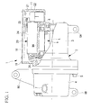
- FIG. 1 is a partial sectional view showing, in a cutaway form, an inverter accommodating section of an inverter-integrated electric compressor according to a first embodiment of the present invention.
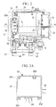
- Fig. 2 is a plan view of a state in which a cover member thereof is removed.
- An inverter-integrated electric compressor 1 includes a housing 2 that forms the outer shell thereof.
- the housing 2 is constructed by securely tightening integrally a motor housing 3 for accommodating an electric motor 9 and a compressor housing 4 for accommodating a compressing mechanism, which is not shown in the drawing, with bolts 5.
- the motor housing 3 and the compressor housing 4 are pressure-resistant containers and are formed of aluminum alloy by aluminum die-casting.
- the electric motor 9 and the compressing mechanism, which is not shown in the drawing, accommodated inside the housing 2 are linked via a motor shaft 10 (see Fig. 1 ), and the compressing mechanism is configured to be driven by rotation of the electric motor 9.
- a refrigerant suction port 6 (see Fig. 2 ) is provided at one end (on the right side in Fig. 1 ) of the motor housing 3, so that low-temperature, low-pressure refrigerant gas taken in from this refrigerant suction port 6 into the motor housing 3 flows around the electric motor 9 in the motor axis L direction and is then taken into the compressing mechanism, where it is compressed.
- High-temperature, high-pressure refrigerant gas compressed by the compressing mechanism is released into the compressor housing 4 and is then expelled to the outside via a discharge port 7 provided at the other end (on the left side in Fig. 1 ) of the compressor housing 4.
- the housing 2 has three mounting legs 8A, 8B, and 8C: two at a lower part at one end (on the right side in Fig. 1 ) of the motor housing 3 and a lower part one end (on the left side in Fig. 1 ) of the compressor housing 4, and one at an upper part of the compressor housing 4.
- the inverter-integrated electric compressor 1 is mounted by securing these mounting legs 8A, 8B, and 8C to a side wall etc. of a driving motor, which is provided inside the engine compartment of the vehicle, with a bracket and bolts.
- the inverter-integrated electric compressor 1 is usually cantilevered at three points on the upper and lower sides with a securing bracket such that the motor shaft direction L is in the front-to-back direction or the left-to-right direction of the vehicle.
- FIG. 1 is a partial longitudinal sectional view showing, in a cutaway form, the inverter accommodating section 11.
- the inverter accommodating section 11 is shaped like a box that is open at the top and surrounded by a periphery wall having a predetermined height. The upper opening is sealed with a cover member 18 secured with screws 19, with a sealing material (not shown) therebetween.
- Two power-supply-cable lead-out holes 12 and 13 are provided on a side surface of the inverter accommodating section 11 so that a power supply, such as a generator or a battery, and an inverter device 20 mounted inside the inverter accommodating section 11 can be connected via two P-N power-supply cables 14 and 15.
- the inverter device 20 mounted inside the inverter accommodating section 11 is constructed of P-N terminals 16 and 17 to be connected to the power-supply cables 14 and 15; high-voltage components, such as a head capacitor 21, an inductor coil 22, and a common mode coil 23, which are provided on a high-voltage power supply line; an inverter module 24 that forms the core of the inverter device 20; a high-voltage bus-bar 25 including integrated a plurality of bus bars, which constitute the electrical wiring among the high-voltage components, the P-N terminals 16 and 17, and the inverter module 24, inside the inverter device 20, and being composed of insert-molded insulating resin material; and a glass-insulated terminal 26 that supplies three-phase AC power, which is converted at the inverter device 20, to the electric motor 9.
- high-voltage components such as a head capacitor 21, an inductor coil 22, and a common mode coil 23, which are provided on a high-voltage power supply line
- an inverter module 24 that forms the core of the invert
- the inverter module 24 is a modularized component formed by integrating a power circuit board, on which are mounted a plurality of semiconductor power switching devices (power devices, such as IGBTs) (not shown) and a power-system circuit, and a control board (printed board), which is provided with control and communication circuits having devices operating at low voltage, such as a CPU.
- the external shape of this inverter module 24 is shown in Figs. 3A to 3D .
- the inverter module 24 is constructed of a module main body 27 that is a substantially cuboid box shape with a bottom surface, and the devices, the electronic components, the circuit, and so on are mounted in the interior thereof.
- An input-side P-N terminal 28 provided on the inverter module 24 is connected to the high-voltage power supply line connected to the P-N terminals 16 and 17 via the high-voltage bus-bar 25, and output-side U-V-W terminals 29 are connected to the glass-insulated terminal 26.
- Attachment legs 30A to 30D for securely tightening the inverter module 24 with screws 31 inside the inverter accommodating section 11 are provided at both ends of two opposing side surfaces of the module main body 27.
- the attachment legs 30A and 30B of the four attachment legs 30A to 30D provided at both ends of the side surface provided with the U-V-W terminals 29 project outward and, as shown in Fig. 2 , are securely tightened by the screws 31 inside the inverter accommodating section 11 by utilizing dead space formed at both ends of the glass-insulated terminal 26.
- an aluminum alloy thin plate 32 that contacts the bottom surface of the inverter accommodating section 11 and transmits the heat of the semiconductor power switching devices provided on the inverter module 24 to a refrigerant flowing through the wall thereof into the motor housing 3 is provided.
- DC power supplied from a high-voltage power supply mounted in the vehicle to the P-N terminals 16 and 17 of the inverter device 20 of the electric compressor 1 via the power-supply cables 14 and 15 is regulated by the high-voltage components, such as the head capacitor 21, the inductor coil 22, and the common mode coil 23 and is input to the inverter module 24 via the input-side P-N terminal 28.
- This DC power is converted into three-phase AC power having a control command frequency instructed by a higher order control device (not shown) by the switching operation of the plurality of semiconductor power switching devices (power devices, such as IGBTs) mounted in the inverter module 24 and is then supplied from the U-V-W terminals 29 to the electric motor 9 inside the motor housing 3 via the glass-insulated terminal 26.
- semiconductor power switching devices power devices, such as IGBTs
- the electric motor 9 is rotationally driven at the control command frequency, and the compression mechanism is operated.
- low-temperature, low-pressure refrigerant gas is taken into the motor housing 3 through the refrigerant suction port 6.
- This refrigerant flows around the electric motor 9 to the compressor housing 4 in the motor axis L direction, is taken in to the compression mechanism, compressed to a high-temperature, high-pressure state, and then discharged into the compressor housing 4.
- the high-temperature, high-pressure refrigerant is discharged outside the electric compressor 1 from the discharge port 7.
- the low-temperature, low-pressure refrigerant taken in from the refrigerant suction port 6 to the motor housing 3 and flowing in the motor axis L direction cools the heat-radiating components of the inverter device 20, such as the high-voltage components and the semiconductor power switching devices installed in the inverter accommodating section 11, via the walls of the motor housing 3 and the thin plate 32.
- the inverter module 24 is installed utilizing this dead space.
- the outwardly protruding attachment legs 30A and 30B positioned in the dead space and installing the inverter module 24 so that it sandwiches the glass-insulated terminal 26 from both ends, the inverter module 24 and the glass-insulated terminal 26 can be installed close to each other. In this way, the component layout density inside the inverter accommodating section 11 can be increased.
- the module main body 27 By making the attachment legs 30A and 30B protrude outward from the module main body 27, the module main body 27 can be made more compact by the same amount, and the positioning of the devices, electronic components, and circuits can be facilitated. As a result, the size of the inverter module 24 can be reduced. By a synergistic effect of the increase in the component layout density and the decrease in size of the inverter module 24, the size of the inverter device 20 and the inverter accommodating section 11 can be reduced even more. Consequently, the size and weight of the inverter-integrated electric compressor 1 can be reduced, and the mounting convenience in the vehicle can be improved.
- This embodiment is configured such that the high-voltage components, such as the head capacitor 21, the inductor coil 22, and the common mode coil 23, are positioned to surround the other side surface of the inverter module 24 and such that electrical wiring for the high-voltage power supply line is provided via the high-voltage bus-bar 25.
- the positions of these high-voltage components are not particularly limited.
- the high-voltage bus-bar 25 is disposed in the space above the inverter module 24, and an aluminum alloy shield plate 33 is disposed therebetween so as to block electromagnetic noise transmission from the high-voltage bus-bar 25 to the low-voltage circuit area in the inverter module 24.
- FIG. 4 a second embodiment of the present invention will be described with reference to Fig. 4 .
- This embodiment differs from the above-described first embodiment in the configuration of the attachment legs provided on the inverter module 24. Since other aspects are the same as those in the first embodiment, descriptions thereof will be omitted.
- Fig. 4 in this embodiment, among the four attachment legs 30A to 30D provided on the inverter module 24, not only the attachment legs 30A and 30B but also the other two attachment legs 30C and 30D protrude outward from the module main body 27.
- the inverter module 24 is disposed such that the attachment legs 30A and 30B are disposed in the dead space so as to sandwich the glass-insulated terminal 26 from both ends, and the high-voltage components, such as the head capacitor 21, the inductor coil 22, and the common mode coil 23, are disposed (the head capacitor 21 and the inductor coil 22 are disposed in this embodiment) between the attachment legs 30C and 30D provided on the opposite side surface.
- the electrical components provided between the attachment legs 30C and 30D are not limited to the head capacitor 21 and the inductor coil 22, and other electrical components may of course be provided.
- the component layout density inside the inverter accommodating section 11 can be increased even more. Since the attachment legs 30A to 30D protrude outward from the module main body 27, the inner boards can be simple rectangular shapes. Therefore, the positions of the devices, electronic components, and circuits provided on the boards can be simplified. As a result, the size of the inverter module 24 can be reduced even more. In this way, the size of the inverter device 20 and the inverter accommodating section 11 can be reduced even more.
- the inverter accommodating section 11 is positioned with an offset of dimension H on the rear side of the vehicle in a direction orthogonal to the motor axis L direction with respect to the motor housing 3 having a pressure-resistant structure positioned forward in the vehicle traveling direction.
- the attachment legs 30A to 30D provided on the inverter module 24 are positioned with an offset with respect to the module main body 27, as shown in Fig. 5B .
- the attachment legs 30A to 30D for securing the inverter module 24 to the motor housing 3 with screws can be secured with screws on the motor housing 3 side at substantially equal distances on either side of the motor axis L. Therefore, as shown in Fig. 5A , screw holes 34 for screwing may be vertically formed in thick-walled parts of the motor housing 3.
- the screw holes 34 can prevent a reduction in the pressure resistance of the motor housing 3, and the screw holes 34 can be formed at positions away from the refrigerant circulation path (positions where the axes of the screws do not penetrate the motor housing 3). In this way, refrigerant gas leakage due to exposure of porosity inside the motor housing 3 to the screw holes 34 can be reduced, and the gas-tightness of the motor housing 3 can be ensured.
- the compressing mechanism provided inside the compressor housing 4 is not particularly limited, and any type of compressing mechanism may be used, e.g., a rotary type, a scroll type, or a swash plate type.
- the inverter accommodating section 11 does not necessarily have to be integrated with the motor housing 3, and separate parts may be assembled into a single unit.
- the installation position of the glass-insulated terminal 26 does not necessarily have to be at the front end of the motor housing 3 (close to the compressor housing 4) as in the above-described embodiments. Instead, the installation position may be at the end edge or the side of the motor housing 3. In such a case, the installation direction and positions of the inverter module 24 and other electrical components are appropriately changed in accordance with the change.
Landscapes
- Engineering & Computer Science (AREA)
- Microelectronics & Electronic Packaging (AREA)
- Mechanical Engineering (AREA)
- General Engineering & Computer Science (AREA)
- Power Engineering (AREA)
- Compressor (AREA)
- Inverter Devices (AREA)
Abstract
Description
- The present invention relates to an inverter-integrated electric compressor for a vehicle air-conditioner in which an inverter accommodating section is provided on the periphery of a housing accommodating an electric motor and a compressing mechanism, and an inverter device is accommodated in the interior thereof.
- Recently, various inverter-integrated electric compressors constructed by integrating inverter devices have been proposed as inverter-integrated electric compressors for vehicle air-conditioners. Such an inverter-integrated electric compressor for a vehicle air-conditioner is provided with an inverter accommodating section (inverter box) that is disposed on the periphery of a housing accommodating an electric motor and a compressing mechanism, and an inverter device that is accommodated in the interior thereof that converts DC power supplied from a high-voltage power supply into three-phase AC power and supplies it to the electric motor via a glass-insulated terminal. In this way, the rotational speed of the electric compressor can vary in response to the air conditioning load. An example of such an inverter-integrated electric compressor is that described in, for example, Patent Document 1.
- As described in Patent Document 1, the inverter device includes a power circuit board on which are mounted semiconductor power switching devices to which high voltage is usually input; a control board (printed board) on which control and communication circuits that operate at low voltage are mounted; and high-voltage components, such as a head capacitor (smoothing capacitor), an inductor coil, and a common mode coil, that are connected to a high-voltage power supply line, wherein these components are compactly accommodated in an inverter accommodating section (inverter box or frame section).
-
- Patent Document 1: Publication of Japanese Patent No.
3786356 - With the increasing of components density in the engine compartments of vehicles, there is a need for reducing the size of compressors for vehicle air conditioners even more in order to ensure their mounting convenience. Therefore, for an inverter-integrated electric compressor having an integrated inverter device, there is a strong need for reducing the size of the inverter accommodating section containing the inverter device. To satisfy this need to reduce the size of the inverter accommodating section, work is in progress to modularize the inverter device integrated with the power circuit board and control board (printed board).
- However, even when making a compact structure by integrally modularizing the power circuit board and control board (printed board) of inverter device with, the size of the inverter device and the inverter accommodating section cannot be sufficiently reduced. In other words, in addition to the power circuit board and the control board, inside the inverter accommodating section, there are provided P-N terminals connected to a high-voltage cable; high-voltage components, such as a head capacitor, an inductor coil, and a common mode coil, connected to a high-voltage power supply line thereof; a high-voltage bus-bar constituting electrical wiring among the high-voltage components, the P-N terminals, and the power circuit board; and electrical components, such as a glass-insulated terminal, for supplying three-phase AC power converted at the inverter device to an electric motor. The positional structure with respect to these electrical components is the key to increasing the components density in the inverter accommodating section. There is still some margin for improvement in the size reduction of the inverter accommodating section.
- The present invention has been conceived in light of the circumstances described above, and it is an object of the present invention to provide an inverter-integrated electric compressor capable of modularizing the inverter device integrated with the power circuit board and control board and of further reducing the size of the inverter device and the accommodating section thereof by improving the positional structure with respect to other electrical components.
- To solve the problems described above, the inverter-integrated electric compressor according to the present invention provides the following solutions.
Specifically, an inverter-integrated electric compressor according to an aspect of the present invention is provided with an inverter accommodating section on a periphery of a housing accommodating an electric motor and a compressing mechanism, and an inverter device that converts DC power supplied from a high-voltage power supply into three-phase AC power and supplies the three-phase AC power to the electric motor in the housing via a glass-insulated terminal is accommodated inside thereof, wherein the inverter device includes an inverter module constructed by integrally modularizing a power circuit board on which a semiconductor switching device and so on are mounted and a control board on which control and communication circuits and so on operating at low voltage are mounted, wherein attachment legs protruding outward from a module main body are provided at both ends of at least one side surface of the inverter module, and wherein the inverter module is accommodated in the inverter accommodating section with the attachment legs positioned in spaces at both ends of the glass-insulated terminal. - According to the above-described aspect, since the inverter module constructed by integrally modularizing the power circuit board and the control board of the inverter device is provided, and the attachment legs provided on one side surface protrude from the module main body, the size of the module main body can be reduced by an amount corresponding to the outward protrusion of the attachment legs. Moreover, since the inverter module is accommodated inside the inverter accommodating section with the outwardly protruding attachment legs positioned in spaces at both ends of the glass-insulated terminal, the inverter module can be installed by efficiently utilizing the dead space formed at both ends of the glass-insulated terminal. By such a synergistic effect, the inverter device and the inverter accommodating section can be made smaller and even more compact. Accordingly, the size and weight of the inverter-integrated electric compressor can be reduced even more, and the mounting convenience can be improved.
- With the above-described aspect, the inverter module may be substantially cuboid, and the attachment legs provided at both ends of two opposing side surfaces thereof may all protrude outward from the module main body.
- According to the above-described aspect, since all attachment legs provided at both ends of two opposing side surfaces of the substantially cuboid inverter module protrude outward from the module main body, the shape of the boards constituting the inverter module can be simple rectangles. In this way, the positions of the devices, electronic components, circuits, and so on provided on the boards can be simplified, and, as a result, the size of the inverter module can be reduced. Accordingly, the size of the inverter device and the inverter accommodating section can be reduced even more.
- With the above-described configuration, other electrical components constituting the inverter device may be positioned in a space between the attachment legs provided on the other side surfaces of the two opposing side surfaces of the inverter module.
- According to the above-described configuration, since other electrical components, such as a capacitor or an inductor, constituting the inverter device are positioned in a space between the attachment legs provided on the other side surface of the two opposing side surfaces of the inverter module, space inside the inverter accommodating section can be utilized efficiently, and the components density can be increased even more. In this way, the size of the inverter device and the inverter accommodating section can be reduced even more.
- With the above-described configuration, the attachment legs provided on each side surfaces of the two opposing side surfaces of the inverter module may be positioned with an offset in a direction orthogonal to a motor axis direction of the electric motor with respect to the module main body.
- According to the above-described configuration, since the attachment legs provided on each side surface of the two opposing side surfaces of the inverter module are positioned with an offset in a direction orthogonal to a motor axis direction of the electric motor with respect to the module main body, when the inverter accommodating section and the inverter device are disposed with an offset in a direction orthogonal to the motor axis direction with respect to the housing and when a structure for protecting the high-voltage system in a crash is provided, the attachment legs of the inverter module can be secured with screws on the housing side at substantially equal distances on either side of the motor axis. Therefore, screw holes for screwing may be vertically formed at thick-walled parts of the housing. In this way, the screw holes can prevent a reduction in the pressure resistance strength of the housing, and the screw holes can be formed at positions away from the refrigerant circulation path (positions where the axes of the screws do not penetrate the motor housing). In this way, refrigerant gas leakage due to exposure of porosity inside the housing to the screw holes can be reduced, and the gas-tightness of the housing can be ensured.
- According to the present invention, the module main body can be made more compact by making the attachment legs of the inverter module protrude outward. Moreover, by installing the inverter modules with the attachment legs positioned in spaces at both ends of the glass-insulated terminal, the inverter module can be installed by efficiently utilizing dead space formed at both ends of the glass-insulated terminal. Therefore, by such a synergistic effect, the inverter device and the inverter accommodating section can be made even more compact, the inverter-integrated electric compressor can be made even more compact and lightweight, and the mounting convenience thereof can be improved.
-
- [
Fig. 1] Fig. 1 is a partial longitudinal sectional view showing, in a cutaway form, an inverter accommodating section of an inverter-integrated electric compressor according to a first embodiment of the present invention. - [
Fig. 2] Fig. 2 is a plan view of a state in which a cover member of the inverter accommodating section of the inverter-integrated electric compressor illustrated inFig. 1 is removed. - [
Fig. 3A] Fig. 3A is a plan view of an inverter module of the inverter-integrated electric compressor illustrated inFig. 1 . - [
Fig. 3B] Fig. 3B is a lower view of the inverter module of the inverter-integrated electric compressor illustrated inFig. 1 . - [
Fig. 3C] Fig. 3C is a right-side view of the inverter module of the inverter-integrated electric compressor illustrated inFig. 1 . - [
Fig. 3D] Fig. 3D is a bottom view of the inverter module of the inverter-integrated electric compressor illustrated inFig. 1 . - [
Fig. 4] Fig. 4 is a plan view of an inverter module of an inverter-integrated electric compressor according to a second embodiment of the present invention. - [
Fig. 5A] Fig. 5A is a schematic longitudinal sectional view of an inverter module of an inverter-integrated electric compressor according to a third embodiment of the present invention. - [
Fig. 5B] Fig. 5B is a schematic plan view of the inverter module of the inverter-integrated electric compressor according to the third embodiment of the present invention. Explanation of Reference Signs: -
- 1: inverter-integrated electric compressor
- 2: housing
- 9: electric motor
- 11: inverter accommodating section
- 20: inverter device
- 21: head capacitor
- 22: inductor coil
- 24: inverter module
- 26: glass-insulated terminal
- 27: module main body
- 30A, 30B, 30C, 30D: attachment legs
- H: offset dimension
- L: motor axis
- Embodiments of the present invention will be described below with reference to the drawings.
- A first embodiment of the present invention will be described with reference to
Figs. 1 to 3D .
Fig. 1 is a partial sectional view showing, in a cutaway form, an inverter accommodating section of an inverter-integrated electric compressor according to a first embodiment of the present invention.Fig. 2 is a plan view of a state in which a cover member thereof is removed. An inverter-integrated electric compressor 1 includes a housing 2 that forms the outer shell thereof. The housing 2 is constructed by securely tightening integrally amotor housing 3 for accommodating anelectric motor 9 and a compressor housing 4 for accommodating a compressing mechanism, which is not shown in the drawing, withbolts 5. Themotor housing 3 and the compressor housing 4 are pressure-resistant containers and are formed of aluminum alloy by aluminum die-casting. - The
electric motor 9 and the compressing mechanism, which is not shown in the drawing, accommodated inside the housing 2 are linked via a motor shaft 10 (seeFig. 1 ), and the compressing mechanism is configured to be driven by rotation of theelectric motor 9. A refrigerant suction port 6 (seeFig. 2 ) is provided at one end (on the right side inFig. 1 ) of themotor housing 3, so that low-temperature, low-pressure refrigerant gas taken in from thisrefrigerant suction port 6 into themotor housing 3 flows around theelectric motor 9 in the motor axis L direction and is then taken into the compressing mechanism, where it is compressed. High-temperature, high-pressure refrigerant gas compressed by the compressing mechanism is released into the compressor housing 4 and is then expelled to the outside via a discharge port 7 provided at the other end (on the left side inFig. 1 ) of the compressor housing 4. - The housing 2 has three mounting
legs Fig. 1 ) of themotor housing 3 and a lower part one end (on the left side inFig. 1 ) of the compressor housing 4, and one at an upper part of the compressor housing 4. The inverter-integrated electric compressor 1 is mounted by securing these mountinglegs - A box-shaped
inverter accommodating section 11 is integrated with the periphery of themotor housing 3 at the upper section thereof.Fig. 1 is a partial longitudinal sectional view showing, in a cutaway form, theinverter accommodating section 11. As shown inFigs. 1 and2 , theinverter accommodating section 11 is shaped like a box that is open at the top and surrounded by a periphery wall having a predetermined height. The upper opening is sealed with acover member 18 secured withscrews 19, with a sealing material (not shown) therebetween. Two power-supply-cable lead-outholes inverter accommodating section 11 so that a power supply, such as a generator or a battery, and aninverter device 20 mounted inside theinverter accommodating section 11 can be connected via two P-N power-supply cables - The
inverter device 20 mounted inside theinverter accommodating section 11 is constructed ofP-N terminals supply cables head capacitor 21, aninductor coil 22, and acommon mode coil 23, which are provided on a high-voltage power supply line; aninverter module 24 that forms the core of theinverter device 20; a high-voltage bus-bar 25 including integrated a plurality of bus bars, which constitute the electrical wiring among the high-voltage components, theP-N terminals inverter module 24, inside theinverter device 20, and being composed of insert-molded insulating resin material; and a glass-insulatedterminal 26 that supplies three-phase AC power, which is converted at theinverter device 20, to theelectric motor 9. - The
inverter module 24 is a modularized component formed by integrating a power circuit board, on which are mounted a plurality of semiconductor power switching devices (power devices, such as IGBTs) (not shown) and a power-system circuit, and a control board (printed board), which is provided with control and communication circuits having devices operating at low voltage, such as a CPU. The external shape of thisinverter module 24 is shown inFigs. 3A to 3D . Theinverter module 24 is constructed of a modulemain body 27 that is a substantially cuboid box shape with a bottom surface, and the devices, the electronic components, the circuit, and so on are mounted in the interior thereof. An input-side P-N terminal 28 provided on theinverter module 24 is connected to the high-voltage power supply line connected to theP-N terminals bar 25, and output-side U-V-Wterminals 29 are connected to the glass-insulatedterminal 26. -
Attachment legs 30A to 30D for securely tightening theinverter module 24 withscrews 31 inside theinverter accommodating section 11 are provided at both ends of two opposing side surfaces of the modulemain body 27. Theattachment legs attachment legs 30A to 30D provided at both ends of the side surface provided with theU-V-W terminals 29 project outward and, as shown inFig. 2 , are securely tightened by thescrews 31 inside theinverter accommodating section 11 by utilizing dead space formed at both ends of the glass-insulatedterminal 26. On the bottom surface of the modulemain body 27, an aluminum alloythin plate 32 that contacts the bottom surface of theinverter accommodating section 11 and transmits the heat of the semiconductor power switching devices provided on theinverter module 24 to a refrigerant flowing through the wall thereof into themotor housing 3 is provided. - According to this embodiment with the above-described configuration, the following advantages are achieved.
DC power supplied from a high-voltage power supply mounted in the vehicle to theP-N terminals inverter device 20 of the electric compressor 1 via the power-supply cables head capacitor 21, theinductor coil 22, and thecommon mode coil 23 and is input to theinverter module 24 via the input-side P-Nterminal 28. This DC power is converted into three-phase AC power having a control command frequency instructed by a higher order control device (not shown) by the switching operation of the plurality of semiconductor power switching devices (power devices, such as IGBTs) mounted in theinverter module 24 and is then supplied from theU-V-W terminals 29 to theelectric motor 9 inside themotor housing 3 via the glass-insulatedterminal 26. - In this way, the
electric motor 9 is rotationally driven at the control command frequency, and the compression mechanism is operated. By operating the compression mechanism, low-temperature, low-pressure refrigerant gas is taken into themotor housing 3 through therefrigerant suction port 6. This refrigerant flows around theelectric motor 9 to the compressor housing 4 in the motor axis L direction, is taken in to the compression mechanism, compressed to a high-temperature, high-pressure state, and then discharged into the compressor housing 4. The high-temperature, high-pressure refrigerant is discharged outside the electric compressor 1 from the discharge port 7. During this period, the low-temperature, low-pressure refrigerant taken in from therefrigerant suction port 6 to themotor housing 3 and flowing in the motor axis L direction cools the heat-radiating components of theinverter device 20, such as the high-voltage components and the semiconductor power switching devices installed in theinverter accommodating section 11, via the walls of themotor housing 3 and thethin plate 32. - However, in this embodiment, as shown in
Fig. 2 , since dead space is formed at both ends of the glass-insulatedterminal 26 when accommodating and installing theinverter device 20 inside theinverter accommodating section 11, theinverter module 24 is installed utilizing this dead space. In other words, with the outwardlyprotruding attachment legs inverter module 24 so that it sandwiches the glass-insulatedterminal 26 from both ends, theinverter module 24 and the glass-insulatedterminal 26 can be installed close to each other. In this way, the component layout density inside theinverter accommodating section 11 can be increased. - By making the
attachment legs main body 27, the modulemain body 27 can be made more compact by the same amount, and the positioning of the devices, electronic components, and circuits can be facilitated. As a result, the size of theinverter module 24 can be reduced.
By a synergistic effect of the increase in the component layout density and the decrease in size of theinverter module 24, the size of theinverter device 20 and theinverter accommodating section 11 can be reduced even more. Consequently, the size and weight of the inverter-integrated electric compressor 1 can be reduced, and the mounting convenience in the vehicle can be improved. - This embodiment is configured such that the high-voltage components, such as the
head capacitor 21, theinductor coil 22, and thecommon mode coil 23, are positioned to surround the other side surface of theinverter module 24 and such that electrical wiring for the high-voltage power supply line is provided via the high-voltage bus-bar 25. However, the positions of these high-voltage components are not particularly limited. The high-voltage bus-bar 25 is disposed in the space above theinverter module 24, and an aluminumalloy shield plate 33 is disposed therebetween so as to block electromagnetic noise transmission from the high-voltage bus-bar 25 to the low-voltage circuit area in theinverter module 24. - Next, a second embodiment of the present invention will be described with reference to
Fig. 4 .
This embodiment differs from the above-described first embodiment in the configuration of the attachment legs provided on theinverter module 24. Since other aspects are the same as those in the first embodiment, descriptions thereof will be omitted.
As shown inFig. 4 , in this embodiment, among the fourattachment legs 30A to 30D provided on theinverter module 24, not only theattachment legs attachment legs main body 27. - Then, the
inverter module 24 is disposed such that theattachment legs terminal 26 from both ends, and the high-voltage components, such as thehead capacitor 21, theinductor coil 22, and thecommon mode coil 23, are disposed (thehead capacitor 21 and theinductor coil 22 are disposed in this embodiment) between theattachment legs attachment legs head capacitor 21 and theinductor coil 22, and other electrical components may of course be provided. - As described above, since all four
attachment legs 30A to 30D provided on theinverter module 24 protrude outward from the modulemain body 27 and the electrical components, such as the glass-insulatedterminal 26, thehead capacitor 21, and theinductor coil 22, are disposed between theattachment legs attachment legs inverter accommodating section 11 can be increased even more. Since theattachment legs 30A to 30D protrude outward from the modulemain body 27, the inner boards can be simple rectangular shapes. Therefore, the positions of the devices, electronic components, and circuits provided on the boards can be simplified. As a result, the size of theinverter module 24 can be reduced even more. In this way, the size of theinverter device 20 and theinverter accommodating section 11 can be reduced even more. - Next, a third embodiment of the present invention will be described with reference to
Fig. 5 .
This embodiment differs from the above-described first embodiment in the positional structure of theinverter accommodating section 11 and theinverter device 20 with respect to themotor housing 3. Since other aspects are the same as those in the first embodiment, descriptions thereof will be omitted.
In this embodiment, as shown inFig. 5 , to protect the high-voltage system of theinverter device 20 when the vehicle is in a crash, theinverter accommodating section 11 is positioned with an offset of dimension H on the rear side of the vehicle in a direction orthogonal to the motor axis L direction with respect to themotor housing 3 having a pressure-resistant structure positioned forward in the vehicle traveling direction. According to this structure, theattachment legs 30A to 30D provided on theinverter module 24 are positioned with an offset with respect to the modulemain body 27, as shown inFig. 5B . - According to this embodiment, even when the
inverter accommodating section 11 and theinverter device 20 are positioned with an offset in a direction orthogonal to the motor axis L direction with respect to themotor housing 3 and the high-voltage system is protected against a crash, theattachment legs 30A to 30D for securing theinverter module 24 to themotor housing 3 with screws can be secured with screws on themotor housing 3 side at substantially equal distances on either side of the motor axis L.
Therefore, as shown inFig. 5A , screw holes 34 for screwing may be vertically formed in thick-walled parts of themotor housing 3. Consequently, the screw holes 34 can prevent a reduction in the pressure resistance of themotor housing 3, and the screw holes 34 can be formed at positions away from the refrigerant circulation path (positions where the axes of the screws do not penetrate the motor housing 3). In this way, refrigerant gas leakage due to exposure of porosity inside themotor housing 3 to the screw holes 34 can be reduced, and the gas-tightness of themotor housing 3 can be ensured. - The present invention is not limited to the embodiments described above, and various modifications may be made so long as they do not depart from the spirit of the invention. For example, the compressing mechanism provided inside the compressor housing 4 is not particularly limited, and any type of compressing mechanism may be used, e.g., a rotary type, a scroll type, or a swash plate type. Moreover, the
inverter accommodating section 11 does not necessarily have to be integrated with themotor housing 3, and separate parts may be assembled into a single unit. - Furthermore, the installation position of the glass-insulated
terminal 26 does not necessarily have to be at the front end of the motor housing 3 (close to the compressor housing 4) as in the above-described embodiments. Instead, the installation position may be at the end edge or the side of themotor housing 3. In such a case, the installation direction and positions of theinverter module 24 and other electrical components are appropriately changed in accordance with the change.
Claims (5)
- An inverter-integrated electric compressor in which an inverter accommodating section is provided on a periphery of a housing accommodating an electric motor and a compressing mechanism, and an inverter device that converts DC power supplied from a high-voltage power supply into three-phase AC power and supplies the three-phase AC power to the electric motor in the housing via a glass-insulated terminal is accommodated inside thereof,
wherein the inverter device includes an inverter module constructed by integrally modularizing a power circuit board on which a semiconductor switching device and so on are mounted and a control board on which control and communication circuits and so on operating at low voltage are mounted,
wherein attachment legs protruding outward from a module main body are provided at both ends of at least one side surface of the inverter module, and
wherein the inverter module is accommodated in the inverter accommodating section by positioning the attachment legs in spaces at both ends of the glass-insulated terminal. - The inverter-integrated electric compressor according to Claim 1, wherein the inverter module is substantially cuboid, and the attachment legs provided at both ends of two opposing side surfaces thereof all protrude outward from the module main body.
- The inverter-integrated electric compressor according to Claim 2, wherein other electrical component constituting the inverter device are positioned in a space between the attachment legs provided on the other side surfaces of the two opposing side surfaces of the inverter module.
- The inverter-integrated electric compressor according to Claim 2, wherein the attachment legs provided on each side surfaces of the two opposing side surfaces of the inverter module are positioned with an offset in a direction orthogonal to a motor axis direction of the electric motor with respect to the module main body.
- The inverter-integrated electric compressor according to Claim 3, wherein the attachment legs provided on each side surfaces of the two opposing side surfaces of the inverter module are positioned with an offset in a direction orthogonal to a motor axis direction of the electric motor with respect to the module main body.
Applications Claiming Priority (2)
| Application Number | Priority Date | Filing Date | Title |
|---|---|---|---|
| JP2007288813A JP5221935B2 (en) | 2007-11-06 | 2007-11-06 | Inverter-integrated electric compressor |
| PCT/JP2008/070004 WO2009060810A1 (en) | 2007-11-06 | 2008-11-04 | Inverter-integrated electric compressor |
Publications (3)
| Publication Number | Publication Date |
|---|---|
| EP2206922A1 true EP2206922A1 (en) | 2010-07-14 |
| EP2206922A4 EP2206922A4 (en) | 2017-03-29 |
| EP2206922B1 EP2206922B1 (en) | 2018-08-15 |
Family
ID=40625701
Family Applications (1)
| Application Number | Title | Priority Date | Filing Date |
|---|---|---|---|
| EP08847582.7A Active EP2206922B1 (en) | 2007-11-06 | 2008-11-04 | Inverter-integrated electric compressor |
Country Status (4)
| Country | Link |
|---|---|
| US (1) | US7973439B2 (en) |
| EP (1) | EP2206922B1 (en) |
| JP (1) | JP5221935B2 (en) |
| WO (1) | WO2009060810A1 (en) |
Cited By (2)
| Publication number | Priority date | Publication date | Assignee | Title |
|---|---|---|---|---|
| EP3240159A1 (en) * | 2016-04-28 | 2017-11-01 | Valeo Systemes de Controle Moteur | Electrical connection bar for exchanging electric energy between an electrical apparatus and an electricity network |
| EP2662566A4 (en) * | 2011-01-07 | 2018-01-10 | Mitsubishi Heavy Industries, Ltd. | Compressor motor and electric compressor using same |
Families Citing this family (18)
| Publication number | Priority date | Publication date | Assignee | Title |
|---|---|---|---|---|
| DE102007034915B4 (en) * | 2007-07-24 | 2011-01-05 | Sew-Eurodrive Gmbh & Co. Kg | Motor connection box and inverter motor |
| JP5582749B2 (en) | 2009-09-24 | 2014-09-03 | 三菱重工業株式会社 | Inverter-integrated electric compressor |
| JP4958988B2 (en) | 2010-03-30 | 2012-06-20 | 株式会社豊田自動織機 | Electric compressor |
| KR101748440B1 (en) * | 2010-08-17 | 2017-07-04 | 학교법인 두원학원 | Structure of electric Compressor of vehicle |
| US8546984B2 (en) * | 2010-11-03 | 2013-10-01 | Nidec Motor Corporation | Pump motor control assembly |
| US20120112608A1 (en) * | 2010-11-04 | 2012-05-10 | Remy Technologies, L.L.C. | Electric machine having an integrated inverter |
| JP5821387B2 (en) * | 2011-08-09 | 2015-11-24 | スズキ株式会社 | Vehicle inverter mounting structure |
| JP5874838B2 (en) * | 2012-09-19 | 2016-03-02 | 日産自動車株式会社 | Mounting structure of high-power unit for electric vehicle |
| EP2899866B1 (en) * | 2012-09-19 | 2017-05-10 | Nissan Motor Co., Ltd. | Power conversion device to be mounted in electric-powered vehicle |
| KR101337542B1 (en) * | 2013-09-13 | 2013-12-06 | 국방과학연구소 | Electric propulsion system of electric vehicle |
| DE102014003381A1 (en) | 2014-03-06 | 2015-09-10 | Wabco Gmbh | magnetic valve |
| JP2016153606A (en) * | 2015-02-20 | 2016-08-25 | 株式会社豊田自動織機 | Electric compressor |
| JP6256382B2 (en) * | 2015-02-27 | 2018-01-10 | 株式会社豊田自動織機 | Electric compressor |
| CN108995505B (en) * | 2015-03-20 | 2022-04-12 | 翰昂汽车零部件有限公司 | Electric compressor converter cooling device and converter assembly provided with same |
| JP6550893B2 (en) * | 2015-04-24 | 2019-07-31 | 日産自動車株式会社 | Machine-electric integrated unit |
| JP7261603B2 (en) * | 2019-02-13 | 2023-04-20 | 日立Astemo株式会社 | Electric driving device and electric power steering device |
| JP7829692B2 (en) * | 2022-07-05 | 2026-03-13 | 三菱重工エンジン&ターボチャージャ株式会社 | Inverter and electric compressor |
| CN122003806A (en) * | 2023-11-29 | 2026-05-08 | 尼得科株式会社 | Power conversion device and motor module |
Family Cites Families (17)
| Publication number | Priority date | Publication date | Assignee | Title |
|---|---|---|---|---|
| EP1043570A3 (en) * | 1999-04-08 | 2004-06-23 | Alps Electric Co., Ltd. | Rotational angle sensor |
| FR2805121B1 (en) * | 2000-02-11 | 2002-04-26 | Leroy Somer | MODULAR CONVERTER |
| FR2806223B1 (en) * | 2000-03-10 | 2003-10-03 | Valeo Equip Electr Moteur | POLYPHASE ROTATING ELECTRIC MACHINE |
| JP2002171768A (en) * | 2000-11-29 | 2002-06-14 | Toshiba Corp | Power converter |
| JP3786356B2 (en) | 2002-04-26 | 2006-06-14 | 株式会社デンソー | Inverter-integrated electric compressor for vehicles |
| JP2004190525A (en) * | 2002-12-09 | 2004-07-08 | Denso Corp | Electric compressor for vehicles |
| EP1363026A3 (en) * | 2002-04-26 | 2004-09-01 | Denso Corporation | Invertor integrated motor for an automotive vehicle |
| JP2004190547A (en) * | 2002-12-10 | 2004-07-08 | Denso Corp | Inverter-integrated electric compressor and method of assembling the same |
| DE10312254B4 (en) * | 2003-03-19 | 2007-02-15 | Siemens Ag | traction engine |
| US7197892B2 (en) * | 2003-06-11 | 2007-04-03 | Denso Corporation | Encapsulated electrically driven compressor |
| US7692356B2 (en) * | 2003-06-20 | 2010-04-06 | Siemens Aktiengesellschaft | Electric machine with a circuit support |
| JP4783012B2 (en) * | 2004-12-28 | 2011-09-28 | 日立オートモティブシステムズ株式会社 | Electric power steering motor and manufacturing method thereof |
| JP4718862B2 (en) * | 2005-02-23 | 2011-07-06 | 三菱重工業株式会社 | Electric compressor |
| JP2007282309A (en) * | 2006-04-03 | 2007-10-25 | Denso Corp | Vehicle motor drive device |
| CN102050009B (en) * | 2006-09-07 | 2013-03-13 | 本田技研工业株式会社 | Electrical device cooling structure in vehicle |
| EP1973222A1 (en) * | 2007-03-20 | 2008-09-24 | ALSTOM Technology Ltd | Electrical machine with a matrix converter |
| US8134343B2 (en) * | 2007-04-27 | 2012-03-13 | Flextronics International Kft | Energy storage device for starting engines of motor vehicles and other transportation systems |
-
2007
- 2007-11-06 JP JP2007288813A patent/JP5221935B2/en active Active
-
2008
- 2008-11-04 EP EP08847582.7A patent/EP2206922B1/en active Active
- 2008-11-04 WO PCT/JP2008/070004 patent/WO2009060810A1/en not_active Ceased
- 2008-11-04 US US12/442,788 patent/US7973439B2/en active Active
Cited By (3)
| Publication number | Priority date | Publication date | Assignee | Title |
|---|---|---|---|---|
| EP2662566A4 (en) * | 2011-01-07 | 2018-01-10 | Mitsubishi Heavy Industries, Ltd. | Compressor motor and electric compressor using same |
| EP3240159A1 (en) * | 2016-04-28 | 2017-11-01 | Valeo Systemes de Controle Moteur | Electrical connection bar for exchanging electric energy between an electrical apparatus and an electricity network |
| FR3050878A1 (en) * | 2016-04-28 | 2017-11-03 | Valeo Systemes De Controle Moteur | ELECTRICAL CONNECTION BAR FOR EXCHANGING ELECTRICAL ENERGY BETWEEN AN ELECTRICAL EQUIPMENT AND AN ELECTRICITY NETWORK |
Also Published As
| Publication number | Publication date |
|---|---|
| US7973439B2 (en) | 2011-07-05 |
| US20100181877A1 (en) | 2010-07-22 |
| WO2009060810A1 (en) | 2009-05-14 |
| EP2206922B1 (en) | 2018-08-15 |
| JP5221935B2 (en) | 2013-06-26 |
| JP2009114958A (en) | 2009-05-28 |
| EP2206922A4 (en) | 2017-03-29 |
Similar Documents
| Publication | Publication Date | Title |
|---|---|---|
| US7973439B2 (en) | Inverter-integrated electric compressor | |
| US8257060B2 (en) | Inverter-integrated electric compressor | |
| EP2287467B1 (en) | Inverter-integrated electrically-powered compressor | |
| US20100181876A1 (en) | Inverter-integrated electric compressor | |
| JP5173344B2 (en) | Electric compressor for in-vehicle air conditioner | |
| EP2445099B1 (en) | Inverter module and inverter-unified-type motor-driven compressor using the same | |
| EP2187055A1 (en) | Electric compressor for vehicle-mounted air conditioner | |
| EP2398136B1 (en) | Inverter device and inverter-integrated electric compressor | |
| EP2196674B1 (en) | Compressor for vehicle-mounted air conditioner | |
| EP2197097B1 (en) | Inverter-integrated electric compressor and coil component for inverter thereof | |
| EP2191991A1 (en) | Electric compressor integrated with inverter | |
| JP5595461B2 (en) | Inverter-integrated electric compressor | |
| JP5427416B2 (en) | Control system for air conditioner | |
| EP2362098B1 (en) | Inverter-integrated electric compressor | |
| JP2013021918A (en) | Inverter integrated type electric compressor |
Legal Events
| Date | Code | Title | Description |
|---|---|---|---|
| PUAI | Public reference made under article 153(3) epc to a published international application that has entered the european phase |
Free format text: ORIGINAL CODE: 0009012 |
|
| 17P | Request for examination filed |
Effective date: 20100409 |
|
| AK | Designated contracting states |
Kind code of ref document: A1 Designated state(s): AT BE BG CH CY CZ DE DK EE ES FI FR GB GR HR HU IE IS IT LI LT LU LV MC MT NL NO PL PT RO SE SI SK TR |
|
| AX | Request for extension of the european patent |
Extension state: AL BA MK RS |
|
| DAX | Request for extension of the european patent (deleted) | ||
| REG | Reference to a national code |
Ref country code: DE Ref legal event code: R079 Ref document number: 602008056537 Country of ref document: DE Free format text: PREVIOUS MAIN CLASS: F04B0039000000 Ipc: F04B0035040000 |
|
| RA4 | Supplementary search report drawn up and despatched (corrected) |
Effective date: 20170227 |
|
| RIC1 | Information provided on ipc code assigned before grant |
Ipc: H02M 7/00 20060101ALI20170218BHEP Ipc: F04B 35/04 20060101AFI20170218BHEP Ipc: H02K 11/33 20160101ALI20170218BHEP Ipc: H02K 7/14 20060101ALI20170218BHEP Ipc: H05K 7/14 20060101ALI20170218BHEP |
|
| GRAP | Despatch of communication of intention to grant a patent |
Free format text: ORIGINAL CODE: EPIDOSNIGR1 |
|
| INTG | Intention to grant announced |
Effective date: 20180223 |
|
| GRAS | Grant fee paid |
Free format text: ORIGINAL CODE: EPIDOSNIGR3 |
|
| GRAA | (expected) grant |
Free format text: ORIGINAL CODE: 0009210 |
|
| AK | Designated contracting states |
Kind code of ref document: B1 Designated state(s): AT BE BG CH CY CZ DE DK EE ES FI FR GB GR HR HU IE IS IT LI LT LU LV MC MT NL NO PL PT RO SE SI SK TR |
|
| REG | Reference to a national code |
Ref country code: CH Ref legal event code: EP Ref country code: GB Ref legal event code: FG4D Ref country code: AT Ref legal event code: REF Ref document number: 1030095 Country of ref document: AT Kind code of ref document: T Effective date: 20180815 |
|
| REG | Reference to a national code |
Ref country code: IE Ref legal event code: FG4D |
|
| REG | Reference to a national code |
Ref country code: DE Ref legal event code: R096 Ref document number: 602008056537 Country of ref document: DE |
|
| REG | Reference to a national code |
Ref country code: CH Ref legal event code: PK Free format text: BERICHTIGUNGEN |
|
| REG | Reference to a national code |
Ref country code: NL Ref legal event code: MP Effective date: 20180815 |
|
| REG | Reference to a national code |
Ref country code: LT Ref legal event code: MG4D |
|
| RIC2 | Information provided on ipc code assigned after grant |
Ipc: H02K 11/33 20160101ALI20170218BHEP Ipc: F04B 35/04 20060101AFI20170218BHEP Ipc: H02K 7/14 20060101ALI20170218BHEP Ipc: H05K 7/14 20060101ALI20170218BHEP Ipc: H02M 7/00 20060101ALI20170218BHEP |
|
| REG | Reference to a national code |
Ref country code: AT Ref legal event code: MK05 Ref document number: 1030095 Country of ref document: AT Kind code of ref document: T Effective date: 20180815 |
|
| PG25 | Lapsed in a contracting state [announced via postgrant information from national office to epo] |
Ref country code: FI Free format text: LAPSE BECAUSE OF FAILURE TO SUBMIT A TRANSLATION OF THE DESCRIPTION OR TO PAY THE FEE WITHIN THE PRESCRIBED TIME-LIMIT Effective date: 20180815 Ref country code: LT Free format text: LAPSE BECAUSE OF FAILURE TO SUBMIT A TRANSLATION OF THE DESCRIPTION OR TO PAY THE FEE WITHIN THE PRESCRIBED TIME-LIMIT Effective date: 20180815 Ref country code: NO Free format text: LAPSE BECAUSE OF FAILURE TO SUBMIT A TRANSLATION OF THE DESCRIPTION OR TO PAY THE FEE WITHIN THE PRESCRIBED TIME-LIMIT Effective date: 20181115 Ref country code: GR Free format text: LAPSE BECAUSE OF FAILURE TO SUBMIT A TRANSLATION OF THE DESCRIPTION OR TO PAY THE FEE WITHIN THE PRESCRIBED TIME-LIMIT Effective date: 20181116 Ref country code: BG Free format text: LAPSE BECAUSE OF FAILURE TO SUBMIT A TRANSLATION OF THE DESCRIPTION OR TO PAY THE FEE WITHIN THE PRESCRIBED TIME-LIMIT Effective date: 20181115 Ref country code: AT Free format text: LAPSE BECAUSE OF FAILURE TO SUBMIT A TRANSLATION OF THE DESCRIPTION OR TO PAY THE FEE WITHIN THE PRESCRIBED TIME-LIMIT Effective date: 20180815 Ref country code: NL Free format text: LAPSE BECAUSE OF FAILURE TO SUBMIT A TRANSLATION OF THE DESCRIPTION OR TO PAY THE FEE WITHIN THE PRESCRIBED TIME-LIMIT Effective date: 20180815 Ref country code: SE Free format text: LAPSE BECAUSE OF FAILURE TO SUBMIT A TRANSLATION OF THE DESCRIPTION OR TO PAY THE FEE WITHIN THE PRESCRIBED TIME-LIMIT Effective date: 20180815 Ref country code: IS Free format text: LAPSE BECAUSE OF FAILURE TO SUBMIT A TRANSLATION OF THE DESCRIPTION OR TO PAY THE FEE WITHIN THE PRESCRIBED TIME-LIMIT Effective date: 20181215 |
|
| REG | Reference to a national code |
Ref country code: CH Ref legal event code: PK Free format text: BERICHTIGUNGEN |
|
| RIC2 | Information provided on ipc code assigned after grant |
Ipc: H02K 11/33 20160101ALI20170218BHEP Ipc: H02M 7/00 20060101ALI20170218BHEP Ipc: F04B 35/04 20060101AFI20170218BHEP Ipc: H02K 7/14 20060101ALI20170218BHEP Ipc: H05K 7/14 20060101ALI20170218BHEP |
|
| PG25 | Lapsed in a contracting state [announced via postgrant information from national office to epo] |
Ref country code: ES Free format text: LAPSE BECAUSE OF FAILURE TO SUBMIT A TRANSLATION OF THE DESCRIPTION OR TO PAY THE FEE WITHIN THE PRESCRIBED TIME-LIMIT Effective date: 20180815 Ref country code: HR Free format text: LAPSE BECAUSE OF FAILURE TO SUBMIT A TRANSLATION OF THE DESCRIPTION OR TO PAY THE FEE WITHIN THE PRESCRIBED TIME-LIMIT Effective date: 20180815 Ref country code: LV Free format text: LAPSE BECAUSE OF FAILURE TO SUBMIT A TRANSLATION OF THE DESCRIPTION OR TO PAY THE FEE WITHIN THE PRESCRIBED TIME-LIMIT Effective date: 20180815 |
|
| PG25 | Lapsed in a contracting state [announced via postgrant information from national office to epo] |
Ref country code: EE Free format text: LAPSE BECAUSE OF FAILURE TO SUBMIT A TRANSLATION OF THE DESCRIPTION OR TO PAY THE FEE WITHIN THE PRESCRIBED TIME-LIMIT Effective date: 20180815 Ref country code: RO Free format text: LAPSE BECAUSE OF FAILURE TO SUBMIT A TRANSLATION OF THE DESCRIPTION OR TO PAY THE FEE WITHIN THE PRESCRIBED TIME-LIMIT Effective date: 20180815 Ref country code: CZ Free format text: LAPSE BECAUSE OF FAILURE TO SUBMIT A TRANSLATION OF THE DESCRIPTION OR TO PAY THE FEE WITHIN THE PRESCRIBED TIME-LIMIT Effective date: 20180815 Ref country code: PL Free format text: LAPSE BECAUSE OF FAILURE TO SUBMIT A TRANSLATION OF THE DESCRIPTION OR TO PAY THE FEE WITHIN THE PRESCRIBED TIME-LIMIT Effective date: 20180815 |
|
| REG | Reference to a national code |
Ref country code: DE Ref legal event code: R097 Ref document number: 602008056537 Country of ref document: DE |
|
| PG25 | Lapsed in a contracting state [announced via postgrant information from national office to epo] |
Ref country code: DK Free format text: LAPSE BECAUSE OF FAILURE TO SUBMIT A TRANSLATION OF THE DESCRIPTION OR TO PAY THE FEE WITHIN THE PRESCRIBED TIME-LIMIT Effective date: 20180815 Ref country code: SK Free format text: LAPSE BECAUSE OF FAILURE TO SUBMIT A TRANSLATION OF THE DESCRIPTION OR TO PAY THE FEE WITHIN THE PRESCRIBED TIME-LIMIT Effective date: 20180815 |
|
| PLBE | No opposition filed within time limit |
Free format text: ORIGINAL CODE: 0009261 |
|
| STAA | Information on the status of an ep patent application or granted ep patent |
Free format text: STATUS: NO OPPOSITION FILED WITHIN TIME LIMIT |
|
| REG | Reference to a national code |
Ref country code: CH Ref legal event code: PL |
|
| 26N | No opposition filed |
Effective date: 20190516 |
|
| GBPC | Gb: european patent ceased through non-payment of renewal fee |
Effective date: 20181115 |
|
| PG25 | Lapsed in a contracting state [announced via postgrant information from national office to epo] |
Ref country code: MC Free format text: LAPSE BECAUSE OF FAILURE TO SUBMIT A TRANSLATION OF THE DESCRIPTION OR TO PAY THE FEE WITHIN THE PRESCRIBED TIME-LIMIT Effective date: 20180815 Ref country code: LU Free format text: LAPSE BECAUSE OF NON-PAYMENT OF DUE FEES Effective date: 20181104 |
|
| REG | Reference to a national code |
Ref country code: BE Ref legal event code: MM Effective date: 20181130 |
|
| REG | Reference to a national code |
Ref country code: IE Ref legal event code: MM4A |
|
| PG25 | Lapsed in a contracting state [announced via postgrant information from national office to epo] |
Ref country code: CH Free format text: LAPSE BECAUSE OF NON-PAYMENT OF DUE FEES Effective date: 20181130 Ref country code: LI Free format text: LAPSE BECAUSE OF NON-PAYMENT OF DUE FEES Effective date: 20181130 Ref country code: SI Free format text: LAPSE BECAUSE OF FAILURE TO SUBMIT A TRANSLATION OF THE DESCRIPTION OR TO PAY THE FEE WITHIN THE PRESCRIBED TIME-LIMIT Effective date: 20180815 |
|
| PG25 | Lapsed in a contracting state [announced via postgrant information from national office to epo] |
Ref country code: FR Free format text: LAPSE BECAUSE OF NON-PAYMENT OF DUE FEES Effective date: 20181130 Ref country code: IE Free format text: LAPSE BECAUSE OF NON-PAYMENT OF DUE FEES Effective date: 20181104 |
|
| PG25 | Lapsed in a contracting state [announced via postgrant information from national office to epo] |
Ref country code: BE Free format text: LAPSE BECAUSE OF NON-PAYMENT OF DUE FEES Effective date: 20181130 |
|
| PG25 | Lapsed in a contracting state [announced via postgrant information from national office to epo] |
Ref country code: GB Free format text: LAPSE BECAUSE OF NON-PAYMENT OF DUE FEES Effective date: 20181115 |
|
| PG25 | Lapsed in a contracting state [announced via postgrant information from national office to epo] |
Ref country code: MT Free format text: LAPSE BECAUSE OF NON-PAYMENT OF DUE FEES Effective date: 20181104 |
|
| PG25 | Lapsed in a contracting state [announced via postgrant information from national office to epo] |
Ref country code: TR Free format text: LAPSE BECAUSE OF FAILURE TO SUBMIT A TRANSLATION OF THE DESCRIPTION OR TO PAY THE FEE WITHIN THE PRESCRIBED TIME-LIMIT Effective date: 20180815 |
|
| PG25 | Lapsed in a contracting state [announced via postgrant information from national office to epo] |
Ref country code: PT Free format text: LAPSE BECAUSE OF FAILURE TO SUBMIT A TRANSLATION OF THE DESCRIPTION OR TO PAY THE FEE WITHIN THE PRESCRIBED TIME-LIMIT Effective date: 20180815 |
|
| PG25 | Lapsed in a contracting state [announced via postgrant information from national office to epo] |
Ref country code: HU Free format text: LAPSE BECAUSE OF FAILURE TO SUBMIT A TRANSLATION OF THE DESCRIPTION OR TO PAY THE FEE WITHIN THE PRESCRIBED TIME-LIMIT; INVALID AB INITIO Effective date: 20081104 Ref country code: CY Free format text: LAPSE BECAUSE OF FAILURE TO SUBMIT A TRANSLATION OF THE DESCRIPTION OR TO PAY THE FEE WITHIN THE PRESCRIBED TIME-LIMIT Effective date: 20180815 |
|
| PGFP | Annual fee paid to national office [announced via postgrant information from national office to epo] |
Ref country code: DE Payment date: 20241001 Year of fee payment: 17 |
|
| PGFP | Annual fee paid to national office [announced via postgrant information from national office to epo] |
Ref country code: IT Payment date: 20241010 Year of fee payment: 17 |