EP2206537B1 - Storage cart for backboard replacement system - Google Patents
Storage cart for backboard replacement system Download PDFInfo
- Publication number
- EP2206537B1 EP2206537B1 EP10075007A EP10075007A EP2206537B1 EP 2206537 B1 EP2206537 B1 EP 2206537B1 EP 10075007 A EP10075007 A EP 10075007A EP 10075007 A EP10075007 A EP 10075007A EP 2206537 B1 EP2206537 B1 EP 2206537B1
- Authority
- EP
- European Patent Office
- Prior art keywords
- frame
- carrier unit
- shelf
- backboard
- storage cart
- Prior art date
- Legal status (The legal status is an assumption and is not a legal conclusion. Google has not performed a legal analysis and makes no representation as to the accuracy of the status listed.)
- Not-in-force
Links
- 238000003860 storage Methods 0.000 title claims abstract description 71
- 230000008878 coupling Effects 0.000 claims abstract description 36
- 238000010168 coupling process Methods 0.000 claims abstract description 36
- 238000005859 coupling reaction Methods 0.000 claims abstract description 36
- 230000007246 mechanism Effects 0.000 claims abstract description 35
- 230000033001 locomotion Effects 0.000 claims description 8
- 230000008859 change Effects 0.000 abstract description 15
- 230000000712 assembly Effects 0.000 description 9
- 238000000429 assembly Methods 0.000 description 9
- 238000000034 method Methods 0.000 description 6
- 239000011521 glass Substances 0.000 description 4
- 229910052751 metal Inorganic materials 0.000 description 4
- 239000002184 metal Substances 0.000 description 4
- 239000000463 material Substances 0.000 description 3
- 230000002093 peripheral effect Effects 0.000 description 3
- XEEYBQQBJWHFJM-UHFFFAOYSA-N Iron Chemical compound [Fe] XEEYBQQBJWHFJM-UHFFFAOYSA-N 0.000 description 2
- 229910000831 Steel Inorganic materials 0.000 description 2
- 229910052782 aluminium Inorganic materials 0.000 description 2
- XAGFODPZIPBFFR-UHFFFAOYSA-N aluminium Chemical compound [Al] XAGFODPZIPBFFR-UHFFFAOYSA-N 0.000 description 2
- 238000012423 maintenance Methods 0.000 description 2
- 230000008439 repair process Effects 0.000 description 2
- 238000005096 rolling process Methods 0.000 description 2
- 238000006748 scratching Methods 0.000 description 2
- 230000002393 scratching effect Effects 0.000 description 2
- 238000000926 separation method Methods 0.000 description 2
- 239000010959 steel Substances 0.000 description 2
- 238000005303 weighing Methods 0.000 description 2
- 238000003466 welding Methods 0.000 description 2
- 230000004075 alteration Effects 0.000 description 1
- 230000005540 biological transmission Effects 0.000 description 1
- 239000002131 composite material Substances 0.000 description 1
- 238000010276 construction Methods 0.000 description 1
- 230000003247 decreasing effect Effects 0.000 description 1
- 230000001419 dependent effect Effects 0.000 description 1
- 230000006870 function Effects 0.000 description 1
- 230000005484 gravity Effects 0.000 description 1
- 229910052742 iron Inorganic materials 0.000 description 1
- 238000004519 manufacturing process Methods 0.000 description 1
- 230000004048 modification Effects 0.000 description 1
- 238000012986 modification Methods 0.000 description 1
- 230000001737 promoting effect Effects 0.000 description 1
- 239000007779 soft material Substances 0.000 description 1
- 239000007787 solid Substances 0.000 description 1
- 239000005341 toughened glass Substances 0.000 description 1
- 239000012780 transparent material Substances 0.000 description 1
Images





Classifications
-
- A—HUMAN NECESSITIES
- A63—SPORTS; GAMES; AMUSEMENTS
- A63B—APPARATUS FOR PHYSICAL TRAINING, GYMNASTICS, SWIMMING, CLIMBING, OR FENCING; BALL GAMES; TRAINING EQUIPMENT
- A63B71/00—Games or sports accessories not covered in groups A63B1/00 - A63B69/00
- A63B71/0036—Accessories for stowing, putting away or transporting exercise apparatus or sports equipment
-
- A—HUMAN NECESSITIES
- A63—SPORTS; GAMES; AMUSEMENTS
- A63B—APPARATUS FOR PHYSICAL TRAINING, GYMNASTICS, SWIMMING, CLIMBING, OR FENCING; BALL GAMES; TRAINING EQUIPMENT
- A63B63/00—Targets or goals for ball games
- A63B63/08—Targets or goals for ball games with substantially horizontal opening for ball, e.g. for basketball
- A63B63/083—Targets or goals for ball games with substantially horizontal opening for ball, e.g. for basketball for basketball
-
- A—HUMAN NECESSITIES
- A63—SPORTS; GAMES; AMUSEMENTS
- A63B—APPARATUS FOR PHYSICAL TRAINING, GYMNASTICS, SWIMMING, CLIMBING, OR FENCING; BALL GAMES; TRAINING EQUIPMENT
- A63B71/00—Games or sports accessories not covered in groups A63B1/00 - A63B69/00
- A63B71/02—Games or sports accessories not covered in groups A63B1/00 - A63B69/00 for large-room or outdoor sporting games
- A63B71/023—Supports, e.g. poles
-
- B—PERFORMING OPERATIONS; TRANSPORTING
- B62—LAND VEHICLES FOR TRAVELLING OTHERWISE THAN ON RAILS
- B62B—HAND-PROPELLED VEHICLES, e.g. HAND CARTS OR PERAMBULATORS; SLEDGES
- B62B3/00—Hand carts having more than one axis carrying transport wheels; Steering devices therefor; Equipment therefor
- B62B3/10—Hand carts having more than one axis carrying transport wheels; Steering devices therefor; Equipment therefor characterised by supports specially adapted to objects of definite shape
- B62B3/108—Hand carts having more than one axis carrying transport wheels; Steering devices therefor; Equipment therefor characterised by supports specially adapted to objects of definite shape the objects being plates, doors, panels, or the like
-
- A—HUMAN NECESSITIES
- A63—SPORTS; GAMES; AMUSEMENTS
- A63B—APPARATUS FOR PHYSICAL TRAINING, GYMNASTICS, SWIMMING, CLIMBING, OR FENCING; BALL GAMES; TRAINING EQUIPMENT
- A63B71/00—Games or sports accessories not covered in groups A63B1/00 - A63B69/00
- A63B71/02—Games or sports accessories not covered in groups A63B1/00 - A63B69/00 for large-room or outdoor sporting games
- A63B71/023—Supports, e.g. poles
- A63B2071/025—Supports, e.g. poles on rollers or wheels
-
- A—HUMAN NECESSITIES
- A63—SPORTS; GAMES; AMUSEMENTS
- A63B—APPARATUS FOR PHYSICAL TRAINING, GYMNASTICS, SWIMMING, CLIMBING, OR FENCING; BALL GAMES; TRAINING EQUIPMENT
- A63B2225/00—Miscellaneous features of sport apparatus, devices or equipment
- A63B2225/09—Adjustable dimensions
- A63B2225/093—Height
-
- A—HUMAN NECESSITIES
- A63—SPORTS; GAMES; AMUSEMENTS
- A63B—APPARATUS FOR PHYSICAL TRAINING, GYMNASTICS, SWIMMING, CLIMBING, OR FENCING; BALL GAMES; TRAINING EQUIPMENT
- A63B2225/00—Miscellaneous features of sport apparatus, devices or equipment
- A63B2225/30—Maintenance
-
- A—HUMAN NECESSITIES
- A63—SPORTS; GAMES; AMUSEMENTS
- A63B—APPARATUS FOR PHYSICAL TRAINING, GYMNASTICS, SWIMMING, CLIMBING, OR FENCING; BALL GAMES; TRAINING EQUIPMENT
- A63B2243/00—Specific ball sports not provided for in A63B2102/00 - A63B2102/38
- A63B2243/0037—Basketball
-
- B—PERFORMING OPERATIONS; TRANSPORTING
- B62—LAND VEHICLES FOR TRAVELLING OTHERWISE THAN ON RAILS
- B62B—HAND-PROPELLED VEHICLES, e.g. HAND CARTS OR PERAMBULATORS; SLEDGES
- B62B2206/00—Adjustable or convertible hand-propelled vehicles or sledges
- B62B2206/06—Adjustable or convertible hand-propelled vehicles or sledges adjustable in height
-
- Y—GENERAL TAGGING OF NEW TECHNOLOGICAL DEVELOPMENTS; GENERAL TAGGING OF CROSS-SECTIONAL TECHNOLOGIES SPANNING OVER SEVERAL SECTIONS OF THE IPC; TECHNICAL SUBJECTS COVERED BY FORMER USPC CROSS-REFERENCE ART COLLECTIONS [XRACs] AND DIGESTS
- Y10—TECHNICAL SUBJECTS COVERED BY FORMER USPC
- Y10T—TECHNICAL SUBJECTS COVERED BY FORMER US CLASSIFICATION
- Y10T29/00—Metal working
- Y10T29/49—Method of mechanical manufacture
- Y10T29/49815—Disassembling
-
- Y—GENERAL TAGGING OF NEW TECHNOLOGICAL DEVELOPMENTS; GENERAL TAGGING OF CROSS-SECTIONAL TECHNOLOGIES SPANNING OVER SEVERAL SECTIONS OF THE IPC; TECHNICAL SUBJECTS COVERED BY FORMER USPC CROSS-REFERENCE ART COLLECTIONS [XRACs] AND DIGESTS
- Y10—TECHNICAL SUBJECTS COVERED BY FORMER USPC
- Y10T—TECHNICAL SUBJECTS COVERED BY FORMER US CLASSIFICATION
- Y10T29/00—Metal working
- Y10T29/53—Means to assemble or disassemble
- Y10T29/53983—Work-supported apparatus
Definitions
- This invention relates to basketball goals generally consisting of a backboard assembly, a basketball goal support assembly, and a storage cart used to facilitate replacement of the backboard assembly. More particularly, the present invention relates to a system for replacing the backboard assembly using the storage cart.
- the game of basketball is popular throughout the world. Part of its popularity may stem from the simplicity of equipment used, i.e., at least one elevated basket and a ball. More commonly, the equipment is at least one basketball goal, which includes a backboard, a rim assembly, a basketball goal support, and a basketball. Additionally, its popularity may stem from the fact that basketball can be played outdoors and indoors, which lends itself to be played year round.
- basketball goals are known to deteriorate, break, or even become dated.
- a basketball player can exert enough force and torque on a basketball goal to distort permanently the rim assembly, shatter the backboard, or even break the basketball goal support mechanism.
- the game, practice, or recreation of basketball must be stopped to permit facilities personnel to replace the old basketball goal with a new basketball goal.
- the broken basketball goal is generally moved away on its wheels and replaced with a new basketball goal that is moved in and fixed to the floor.
- the cost and expense of having one or more replacement basketball goals in storage can be great in terms of equipment and inventory space.
- the time to replace the basketball goal can last for about twenty minutes to about one hour or more. During this hiatus, players can cool off, spectators can lose interest, and the total time for the game can be extended for an unreasonable period of time.
- the rim assemblies generally include a rim and a mounting plate. The mounting plate would then attach via a fastener or shaft to a receiving plate that is attached to the backboard.
- the rim assemblies for the outdoors are more inexpensive and lesser in quality than the rim assemblies for the indoors.
- the rim assemblies for the indoors including gymnasiums and arenas, are generally "commercial grade" because of the construction and materials used to account for the amount of use and mobility of basketball goals. Because of this higher quality, indoor basketball goals are more typically replaced with a whole new basketball goal system, instead of replacing the part on the spot.
- US 3 540 753 A discloses a hand truck including a generally horizontal and wheeled base assembly, a framework assembly attached to the base assembly and expending upward therefrom, a generally upright receiving rack having a supporting tip positioned adjacent its lower end portion, and a connecting member having forward and rearward end portions.
- the forward end portion of the connecting member is pivotally attached to the rack adjacent the lower end portion with the general plane of said rack extending laterally of the normal rolling movement of the base assembly and the rearward end portion is pivotally attached to the base assembly.
- the truck further includes lifting means extending between and attached to the framework assembly and the forward end portion of the connecting member whereby the rack may be raised and lowered.
- the rack is with the framework assembly to a forward loading and unloading position in which the lip is generally parallel and closely adjacent to the floor.
- the present invention is defined by storage cart comprising the features of claim 1. Preferred embodiments of this storage cart are represented in the dependent claims.
- a basketball goal that can include one or more couplings that permit the quick change and replacement with another backboard assembly.
- the one or more couplings can also permit, during normal use and impact, the rim to be maintained at its conventional position and effective rigidity.
- the basketball goal may include a quick change backboard bracket system.
- the quick change backboard bracket system can include a backboard, a first yoke member, a rim assembly, a second yoke member, bracing means for coupling the backboard to a basketball goal support, or any combination.
- the backboard can have a peripheral frame with a bracket.
- the first yoke member can include a central plate coupled to the backboard and a left web and a right web fixed to the central plate.
- the left and right webs can extend rearward and each web may have a slot, an opening, or both.
- the rim assembly can be coupled to the central plate of the first yoke member through the backboard.
- the second yoke member can include a middle plate coupled to a basketball goal support, a left arm and a right arm fixed to the middle plate, a coupling shaft, and a connecting pin.
- the left and right arms can extend frontward and each arm may have a first aperture and a second aperture.
- the coupling shaft can be dimensioned to fit within, and positioned through, each first aperture. Additionally, the coupling shaft can be dimensioned to engage the slot of the first yoke member.
- the connecting pin can be dimensioned to engage each opening of the first yoke member and each second aperture of the second yoke member.
- a bracing means can couple the backboard to the basketball goal support and a rim assembly can be coupled to the central plate of the first yoke member through the backboard.
- the quick change backboard bracket system described above can be used with a storage cart, which can support the backboard and rim assembly when being (de)coupled to the basketball goal support.
- the storage cart can be used with other basketball goal systems, where the backboard and rim assembly are removed for storage and/or maintenance.
- the storage cart can include a frame that has a base, a top, and a plurality of upright support members interconnecting the base and the top.
- the frame may also include means for moving the frame, such as a plurality of wheels.
- the means for moving the frame permits the storage cart to move from a storage place to the basketball goal assembly, and back to the storage place.
- the frame can also be easily rotated to allow each side of the frame to be used for storing the backboard and rim assembly.
- the base can have a depth that is greater than a depth of the top to form a taper.
- the taper is sized to permit the backboard to lean securably against the frame.
- the storage cart can also include a carrier unit and a lifting mechanism. The lifting mechanism, attached to the frame and to the carrier unit, is configured to adjust the vertical position of a shelf.
- the carrier unit which is attached to the frame, can include the shelf sized to support the backboard.
- the storage cart also includes a second shelf positioned at the opposite side of the frame as the shelf.
- the second shelf can be vertically adjusted, and a pin-in-hole coupling can be used to couple the second shelf to the frame.
- the storage cart may be configured to include one or more carrier units on more than one side of the storage cart, or one or more second shelf configurations on more than one side.
- the carrier unit can include at least one pair of cross members positioned at lateral sides of the frame, with each cross member having a first end pivotably connected to the frame and a second end attached to the shelf.
- the pair of cross members can be an upper pair and a lower pair.
- the carrier unit can further include at least one lateral member connecting at least one pair of cross members positioned at opposite lateral sides of the frame.
- the carrier unit may further include a pair of upright members and a top member. Each upright member can attach to the second end of the cross members of the upper and the lower pairs to define a lateral edge of the carrier unit to permit each cross member to pivot about the respective second end.
- the top member attached to an upper portion of each upright member, can extend laterally beyond the lateral sides of the frame.
- the top member may include arms at the ends that can be configured to prevent lateral movement of the backboard when placed on the shelf.
- the shelf can be attached to a lower portion of each upright member of the carrier unit.
- the lifting mechanism is configured to urge each cross member to pivot about the first end to adjust the vertical position of the second end and the shelf.
- the lifting mechanism may include a lift jack and a manual crank connected to the lift jack, where the manual crank can be rotated to adjust the vertical position of a movable member of the lift jack.
- the carrier unit can include at least one pair of sleeve members positioned at lateral sides of the frame.
- Each sleeve member can have an outer portion connected to the lifting mechanism and engaged with the shelf.
- Each sleeve may also have an inner portion slidably engaged with the frame.
- the lifting mechanism can urge each sleeve member to slide against the frame to adjust the vertical position of each sleeve member and the shelf.
- the lifting mechanism can include a threaded shaft having one end attached to the carrier unit and a free end, and a manual crank connected to the lifting mechanism having a portion configured to rotate the threaded shaft. The manual crank can be rotated to adjust the vertical position of threaded shaft.
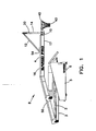
- FIG. 1 is a side view of a basketball goal.
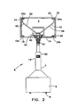
- FIG. 2 is a front view of the basketball goal.
- FIG. 3a is a rear perspective view of a backboard assembly including a rim assembly and a first and second yoke member.
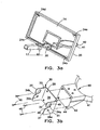
- FIG. 3b is a rear perspective view of a rim assembly and a first yoke member.
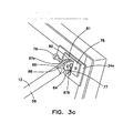
- FIG. 3c is a rear perspective detail view of one corner of the backboard showing a coupling between a corner bracket and a bracing member.
- FIG. 4 is a rear perspective view of the first yoke member decoupled from a second yoke member.
- FIG. 5 is a rear perspective view of the first yoke member coupled to a second yoke member of the example in FIG. 4 .
- FIG. 6a is a front perspective view of a first yoke member decoupled from a second yoke member of an alternative example.
- FIG. 6b is a front perspective view of a first yoke member decoupled from a second yoke member of an alternative example.
- FIG. 7 is a perspective view of a storage cart of an embodiment of the invention.
- FIG. 8 is a perspective view of a frame of the storage cart in FIG. 7 .
- FIG. 9a is a perspective view of a carrier unit of the storage cart in FIG. 7 .
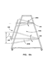
- FIG. 9b is a side view of the carrier unit of FIG. 9a depicting the pivotable motion of the carrier unit.
- FIG. 9c is a perspective view of another carrier unit coupled to the frame of the storage cart.
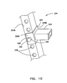
- FIG. 10 is a perspective view a second shelf coupled to the frame of the storage cart.
- FIG. 11a is side view of the storage cart within proximity of the basketball goal assembly depicting using the storage cart.
- FIG. 11b is side view of the storage cart within proximity of the basketball goal assembly depicting using the storage cart.
- FIGS. 1 and 2 shows a side view and a front view a basketball goal system 8 including an illustrative quick change backboard bracket system 10 having a backboard assembly 14 coupled to a basketball goal support assembly 16.
- the backboard assembly 14 can include a backboard 20, a rim assembly 40, and a first yoke member 30, as shown in FIG. 3a .
- the basketball goal support assembly 16 can include a second yoke member 60, bracing means 12 coupled on the upper portion 9 of the backboard 20 to support the basketball goal support assembly 16, and a basketball goal support 50.
- the basketball goal system 8 can be stationary or can be a mobile system.
- An illustrative basketball goal system 8 is a GARED Pro 5017 Portable Basketball Goal System shown in FIGS. 1 and 2 .
- the GARED Pro 5017 Portable Basketball Goal System includes a hydraulic portable backstop 2 for lowering and raising the system, a decreasing trapezoidal extension arm 4 for stability to the backboard 20 and the rim assembly 40, regulation glass competition backboard 20, the rim assembly 40 having a breakaway goal, a base 5, and a plurality of wheels 6 for rolling and maneuvering the system.
- one regulation glass competition backboard 20 is made of a fully tempered glass with a aluminum frame surrounding the glass, with the backboard 20 having a general dimension of about 1.2 m x 1.8 m (48 inches x 72 inches) and weighing about 100 kg (220 pounds).
- the quick change backboard bracket system 10 can allow for a quick and easy removal and replacement of the backboard assembly 14.
- the various components of the quick change backboard bracket system 10 are dimensioned to have tolerances to ensure that the basketball goal system as assembled has the desired stability in the case of a dunk shot or a player hanging on the rim. Furthermore, it is desired that no special tools be required for replacing the backboard assembly 14.
- the backboard 20 of the backboard assembly 14 has a peripheral frame 22 as shown in FIG. 2 .
- the backboard 20 is rectangular; however, the backboard 20 can be any shape known by one of ordinary skill in the art.
- the backboard 20 can be made of glass or other transparent materials or composites, while the peripheral frame 22 can be made in any metal known in the art, such as steel, aluminum or the like.
- the backboard 20 can also have apertures, not shown, that allow fasteners 46 to run through it.
- the backboard 20 can further include at least one bracket 23 that can couple to a bracing member 52.
- a bracket 23 that can couple to a bracing member 52.
- the brackets 23 are corner brackets 24; that is, four corner brackets with one corner bracket 24a being in the upper-right portion of the backboard 20, one corner bracket 24b being in the lower-right portion of the backboard 20, one corner bracket 24c being in the lower-left portion of the backboard 20, and one corner bracket 24d being in the upper-left portion of the backboard 20.
- the corner brackets 24 may be a corner gusset which may have a slot or opening 19 for engaging the bracing member 52.
- the bracing means 12 may have a single bracing member 52. Other embodiments of the bracing means 12 may have two or more bracing members 52.
- the bracing member 52 can have a basketball goal support coupling 54 on a connecting arm portion 17 of the basketball goal support assembly.
- the basketball goal support coupling 54 may be used to couple the backboard 20 to the basketball goal support 50.
- the bracing means 12 can comprise at least one or more supporting members 55, preferably two supporting members 55, 56.
- One embodiment of the bracing means 12 is two supporting members 55, 56, shown in FIG. 2 .
- the two supporting members 55, 56 extend vertically and frontward toward the backboard 20 to couple to the two corner brackets 24a, 24d of the upper portion 9 of the backboard 20 with a pin and hairpin clip retainer 75.
- the pin and hairpin clip retainer 75 preferably includes a supporting plate 81 fixed to each corner bracket 24.
- the supporting plate 81 has two vertically-oriented members 82, 84 extending away from the backboard 20.
- the vertically-oriented members 82, 84 are preferably separated by distance that is substantially the same or slightly greater than the lateral distance of an adjoining member 86 from the supporting members 55, 56 of the bracing means 12.
- the two vertically-oriented members 82, 84 also have an opening 87a, 87b that are axially align with a similar opening 88 in the adjoining member 86.
- the first yoke member 30 can include a central plate 32.
- the central plate 32 can have apertures 28.
- the apertures 28 can be for receiving fasteners 46, which pass through the mounting plate 42, backboard 20, and central plate 32.
- the first yoke member 30 can also include a left web 31 and a right web 33 fixed to the central plate 32.
- the left and right webs 31, 33 can extend rearward away from the backboard 20 in the vertical position, perpendicular to the backboard 20.
- Each web 31, 33 can have a slot 34a, 34b, at least one opening 36a, 36b, or both.
- Each slot 34a, 34b can have one direction or can be multidirectional.
- each slot 34a, 34b in FIG. 3b is bi-directional, with one portion 48 of the slot having a direction that is frontward and upwardly diagonal and with another portion 49 of the slot 34a, 34b having a direction that is upward or vertical and parallel to the backboard 20.
- the open ended slot 134' is bi-directional, with one portion 148 of the slot having a direction that is rearward and/or downwardly diagonal and with another portion 149 of the slot 134' having a direction that is downward or vertical and parallel to the backboard.
- each slot 34a, 34b can have only one direction that is upward, only one direction that is frontward or horizontal, or any other direction.
- each slot 34a, 34b can be created from the top side, from the bottom side, from the front side, or from the rear side of each web 31, 33.
- each slot 34a, 34b is created at the upper portion 35 and from the rear side 37 of each web 31, 33 as shown in FIG. 3b .
- each slot 134' is created at the lower portion 135 and from the front side 137 of each web 131 a, 131 b, 133a, or 133b.
- Each slot 34a, 34b can be dimensioned to receive a coupling shaft 64, as shown in FIG. 4 .
- each slot 34a, 34b can be axially aligned or can be positioned on each web 31, 33 so that each slot 34a, 34b is in mirror symmetry.
- each opening 36a, 36b can be dimensioned to receive a connecting pin 70, shown in FIG. 5 .
- Each opening 36a, 36b can be axially aligned, can be positioned on each web 31, 33, so that each slot 34a, 34b is in mirror symmetry, or both.
- the rim assembly 40 can include the mounting plate 42.
- the mounting plate 42 can have apertures 44 for receiving the fastener 46.
- apertures 44 for receiving the fastener 46.
- four apertures 44 with four fasteners 46 are shown in FIG. 3b .
- Fasteners 46 can be used to run through all these apertures to secure the mounting plate 42 to the back surface of the backboard 20, the backboard 20, and central plate 32 to the front surface of the backboard 20.
- Any suitable fastener known in the art can be used, such as screws, bolts, or rivets.
- the number of fasteners 46 should be the same as the number of apertures 46.
- the rim 41 is mounted so that the rim is in the conventional horizontal position.
- a net 43 as shown in FIGS. 1 and 2 , can be suspended from the rim 41 in the usual manner.
- the quick change backboard bracket system 10 may also include the second yoke member 60, with one embodiment shown in FIG. 4 .
- the second yoke member 60 can include a middle plate 62.
- the middle plate 62 of the second yoke member 60 may be coupled to and may extend from the basketball goal support 50 as shown in FIGS . 1 and 2 .
- the second yoke member 60 and the basketball goal support 50 may be one unit.
- the second yoke member 60 may be a single unit that can be attached to any basketball goal support.
- the second yoke member 60 can also include a left arm 61 and a right arm 63, which can be fixed to the middle plate 62.
- the left and right arms 61, 63 can extend frontward toward the backboard 20 in the vertical position, perpendicular to the backboard 20.
- Each arm 61, 63 can have a first 66a, 66b and a second aperture 68.
- Each first aperture 66a, 66b can be dimensioned to receive the coupling shaft 64, as shown in FIG. 4 .
- the coupling shaft 64 can be dimensioned to fit within and positioned through each first aperture 66a, 66b of the second yoke member 60 and to engage each slot 34a, 34b of the first yoke member 30.
- Means for attaching the coupling shaft 64 to each first aperture 66a, 66b can comprise of welding. Moreover, other means for attaching can include press fitting the coupling shaft 64 within each first aperture 66a, 66b, mechanically expanding the coupling shaft 64 with each first aperture 66a, 66b, or any other means known in the art by one of ordinary skill.
- each second aperture 68 can be dimensioned to receive the connecting pin 70, as shown in FIG. 5 .
- each second aperture 68 can have a circular edge; preferably, each second aperture 68 has an elliptical edge 80 that has a first cross sectional distance 85 in the horizontal direction greater than a second cross sectional distance 83 in the vertical direction, as shown in FIG. 4 .
- the elliptical edge 80 can have the first cross sectional distance 85 that is less than the second cross sectional distance 83. If each second aperture 68 has a circular edge, the second aperture should be slightly larger than the dimension of the opening 36a, 36b of the first yoke member 30.
- the slightly larger dimensioned second aperture or the elliptical edged second aperture would allow for some small margin in error in manufacturing and assembling when coupling the first yoke member 30 to the second yoke member 60.
- having one direction of each slot 34a, 34b be perpendicular to the predominant direction 83 or 85 of the elliptical edge 80 of each second aperture 68 can allow for easier assembly.
- the connecting pin 70 is dimensioned to engage each opening 36a, 36b of the first yoke member 30.
- Means 71 for engaging the connecting pin 70 to and from each opening 36a, 36b and each second aperture 68 can include a retainer pin 72, as shown in FIG. 5 .
- Other means 71 for engaging the connecting pin 70 can be a bolt/nut fastener, a bolt and retainer pin fastener, or any other means known by one of ordinary skill in the art. It is desired that whatever means for engaging the connecting pin 70 can also be quickly disengaged.
- One example is the retainer pin 72, which can be inserted through an opening 73 of the connecting pin 70, around the circumference of the connecting pin 70, or both.
- the first yoke member 30 and the second yoke member 60 can be constructed of a metal channel, e.g., a steel channel or iron channel.
- the first yoke member 30 and the second yoke member 60 can be constructed from multi-metal pieces welded or secured together by any means known by those skilled in the art.
- the arms 61, 63 of the second yoke member 60 can be separated by an outermost lateral distance 69 that is less than an innermost lateral distance 38 of the webs 31, 33 of the first yoke member 30.
- the coupling shaft 64 may have projecting ends 65 to engage each slot 34a, 34b of the first yoke member 30.
- the coupling shaft 64 may also have a lateral dimension greater than an outermost lateral distance 39 of the webs 31, 33 of the first yoke member 30.
- the webs 31, 33 of the first yoke member 30 can be separated by an outermost lateral distance 39 that is less than an innermost lateral distance 67 of the arms 61, 63 of the second yoke member 60.
- the quick change backboard bracket system 110 can include an alternative first yoke member 130 and second yoke member 160.
- the quick change backboard bracket system 110 can include all of the limitations described above.
- each yoke member 130, 160 can include a central plate 132a, 132b.
- Each yoke member 130, 160 can also include a left web 131 a, 131 b and a right web 133a, 133b affixed to the central plate 132a, 132b.
- the left webs 131 a, 131 b and right webs 133a, 133b may extend away from the central plate 132a, 132b.
- the left webs 131 a, 131 b and right webs 133a, 133b can have a first opening 134a, 134b, a second opening 136a, 136b, or both.
- the second openings 136a or 136b in the webs 131 a, 131 b, 133a, 133b of one of the first yoke member 130 and second yoke member 160 can be a closed-ended slot 180.
- the second openings 136a or 136b in the webs 131 a, 131 b, 133a, 133b of another of the first yoke member 130 and second yoke member 160 can be the open-ended slot 134'.
- the central plate 132a of the first yoke member 130 can be coupled through the backboard to a rim assembly, similar to what is shown in FIG. 3a .
- the left web 131 a and the right web 133a of the first yoke member 130 can be mounted in the vertical configuration and can extend away from the backboard.
- the central plate 132b of the second yoke member 160 can be coupled to a basketball goal support.
- Each web 131b, 133b of the second yoke member 160 can be mounted in the vertical configuration and can extend toward the backboard.
- a coupling shaft 164 can be dimensioned to fit within, and positioned through, each first opening 134a or 134b of one of the first yoke member 130 and second yoke member 160. Also, the coupling shaft 164 can be dimensioned to engage either each second opening 136a or 136b of another of the first yoke member 130 and second yoke member 160, whichever is the opposite of the one yoke member having the first openings engaged to the coupling shaft 164.
- a connecting pin 170 can be dimensioned to fit within and to engage to each first opening 134a or 134b of another of the first yoke member 130 and the second yoke member 160, whichever yoke member is opposite to the one that has the first openings engaged to the coupling shaft 164.
- the connecting pin 170 can also be dimensioned to fit within and to engage each second opening 136a or 136b of one of the first yoke member 130 and the second yoke member 160, whichever yoke member is opposite to the one that has the second openings to be engaged to the coupling shaft 164.
- This second opening 136a or 136b can have an elliptical edge.
- the coupling shaft 164 can be dimensioned to fit within, and positioned through, each first opening 134a of the webs 131a, 133a of the first yoke member 130, as shown in FIG. 6a . Additionally, the coupling shaft 164 can be dimensioned to engage each second opening 136b or open-ended slots 134' of the webs 131 b, 133b of the second yoke member 160. Likewise the connecting pin 170 can be dimensioned to fit within and to engage each second opening 136a or closed-ended slots 180 of the webs 131a, 133a of the first yoke member 130 and each first opening 134b of the webs 131 b, 133b of the second yoke member 160.
- the coupling shaft 164 can be dimensioned to fit within, and is positioned through, each first opening 134b of the webs 131b, 133b of the second yoke member 160. Additionally, the coupling shaft 164 can be dimensioned to engage each second opening 136a or open ended slots 134' of the webs 131 a, 133a of the first yoke member 130. Likewise the connecting pin 170 can be dimensioned to fit within and to engage each second opening 136b or closed-ended slot 180 of the webs 131 b, 133b of the second yoke member 160 and each first opening 134a of the webs 131a, 133a of the first yoke member 130.
- Another embodiment provides a method of replacing a backboard assembly 14 using the quick change backboard bracket system 10 or 110.
- the method of replacing is better illustrated by the difference in positions of the yoke members between FIG.4 and FIG.5 .
- the method can comprise the steps of providing a first backboard assembly 14, as described above, a second backboard assembly, not shown but substantially similar to the first backboard assembly 14, and a basketball goal support assembly 16, as described above.
- the connecting pin 70 can be disengaged from each opening 36a, 36b of the first backboard assembly 14 and each second aperture 68 of the basketball goal support assembly 16. If the connecting pin 70 includes a retainer pin 72, the retainer pin 72 is removed before the connecting pin 70 is removed from each opening 36a, 36b and each second aperture 68.
- the bracing member 52 of the basketball goal support assembly 16 can be decoupled from each bracket 23 of the first backboard assembly 14.
- Each slot 34a, 34b of the first backboard assembly 14 also can be disengaged from the coupling shaft 64 of the basketball goal support
- the first backboard assembly 14 can then be removed and set aside and can be replaced with the second backboard assembly.
- Each slot 34a, 34b of the second backboard assembly can be engaged to the coupling shaft 64 of the basketball goal support assembly 16.
- the connecting pin 70 can be engaged to each opening 36a, 36b of the second backboard assembly and each second aperture 68 of the basketball goal support assembly 16.
- the bracing member 52 of the basketball goal support assembly 16 can be coupled to each bracket 23 of the second backboard.
- these steps in combination with the quick change backboard braket system can be can be completed quickly. For instance, the steps may be capable of completion during a timeout or halftime.
- FIG. 7 illustrates a storage cart 200 for supporting the first backboard assembly 14 and used to facilitate replacement of the first backboard assembly 14.
- the storage cart 200 can include a frame 210 having a base 212 and a top 214.
- the base 212 and the top 214 shown in the Figures include one or more first lateral members attached to one or more first cross members.
- the top 214 in FIG. 8 includes a left and a right first cross member 216A, 216B and one first lateral member 218 attached to approximately the center of the left and right first cross members 216A, 216B.
- the base 212 includes a left and a right first cross member 220A, 220B and two first lateral members 222A, 222B attached to the left and right first cross members 220A, 220B.
- the base 212 and the top 214 can be interconnected by one or more first upright members.
- the base 212 and the top 214 are interconnected by four first upright members 224A-D.
- One pair of the first upright members 224A, 224B define a lateral side 228A of the frame 210, while another pair of the first upright members 224C, 224D define another lateral side 228B of the frame 210.
- the ends of the first upright members 224A-D attach to the respective ends of the first cross members 216A, 216B, 220A, 220B of the top 214 and the base 212 to form the lateral sides 228A, 228B.
- first upright members 224A, 224C define a front side 232 of the frame 210
- another pair of the first upright members 224B, 224D define a rear side 234 of the frame 210.
- the base 212 can have a depth that is greater than a depth of the top 214 to form a taper sized to permit the backboard assembly 14 to lean securably against the frame 210.
- the taper can be on at least one of the front side 232, the rear side 234, and the lateral sides 228A, 228B at an angle A of about 3 degrees to about 20 degrees, and preferably 5 degrees, from vertical.
- the front side 232, the rear side 234, or both may be angled toward the center of the frame 210.
- Attached to the base 212 of the frame 210 can be means for moving the storage cart 200 proximate the basketball goal support assembly 16.
- the means for moving can comprise a plurality of wheels 236.
- a wheel 236 can be attached at the four discrete corners of the base 212 of the frame 210, as shown in FIG. 7 .
- the first upright members 224A-D can include a plurality of holes 238 incrementally spaced.
- the spacing of the holes 238 of one first upright member 224B can correspond to the spacing of the holes 238 of another first upright member 224D in order for an attachment to be equally adjusted and level.
- the holes 238 of each of the first upright members 224A-D are equally spaced and aligned.
- the frame 210 is preferably constructed of metal square tubing. However, the frame 210 can be constructed of other materials and in other shapes such as channel, rectangle, angle, round, solid or hollow (tube) suitable to support the weight of one or more backboard assemblies. The material selected may be painted and labeled. Each members of the frame 210 can be attached through welding or the like and/or fasteners such as rivets or nut/bolts.
- the storage cart 200 can be sized to fit within a height of a standard door of about 2.03 m (80 inches) and within a width of about 0.91 m (36 inches) or more. The size of the storage cart 200 can be modified for larger entry ways, for example, for a total width of standard double doors of about 1.5 m (60 inches) or more.
- the storage cart 200 can support one or more backboard assemblies weighing as much as 100 kg (220 pounds). Thus, to support two backboard assemblies the storage cart 200 can support about 200 kg (440 pounds).
- a carrier unit 250 can be provided to support the backboard assembly 14 and move generally in vertical position, relative to the stationary basketball goal assembly 16, in order to facilitate the removal or replacement of the backboard assembly 14.
- the carrier unit 250 can include a shelf 252 that is configured to support the backboard assembly 14.
- a first portion 254 of the carrier unit 250 may be attached to the frame 210, while a second portion 256 may be attached to a lifting mechanism 257.
- FIG. 9a shows the carrier unit 250A having an upper pair of second cross members 260A, 260D and a lower pair of second cross members 260B, 260C which can be positioned adjacent to the lateral sides 228A, 228B of the frame 210.
- Each second cross member 260A-D includes a first end 262 pivotably connected to interior sides of the respective first upright members of the frame 210.
- Each second cross member 260A-D also has a second end 264 that may be attached to the shelf 252.
- the second end 264 of each second cross member 260A-D may be attached to a pair of second upright members 266A, 266B to define a front side 268 of the carrier unit 250A.
- the second end 264 is shown to be interposed between the interior side of the first upright member 224A and the exterior side of the second upright member 266A, as shown in FIG. 7 .
- each second cross member 260A-D can pivot about the respective second end 262, as represented by the arrows, in order for the carrier unit 250A to swing at a large radius of curvature.
- the shelf 252 can attach to a lower portion 271 of the second upright members 266A.
- Each second cross member can be raised and lower between an upper and a lower extreme, as shown by the dashed lines in FIG. 9b .
- the total distance X of vertical adjustment of the shelf 252 between the upper and lower extremes is about 14 inches, as shown in FIG. 9b , although distance X may vary suitably to a distance as determined by one ordinary skilled in the art.
- a physical stop 272 may be attached to the interior side of the first upright members 224A, 224C, as shown in FIG. 7 .
- the physical stop 272 functions as rest for the shelf 252 and/or carrier unit 250A when loaded with the backboard assembly 14.
- a top member 270 can attach to an upper portion 273 of each second upright member 266A, 266B.
- the top member 270 may extend laterally beyond the lateral sides 228A, 228B of the frame 210, and may include arms 274 at the end of the top member 270 configured to prevent lateral movement of the backboard assembly 14.
- the arms 274 can be configured as L-shaped ( FIG. 9a ), with one leg extending out to prevent lateral movement and another leg creating a separation between the backboard assembly 14 and the frame 210 to prevent scratching and/or fracturing of the backboard.
- Another configuration of the arms 274 can include C-shaped, with one leg to prevent lateral movement, one leg to prevent outward movement, and another leg creating a separation between the backboard assembly 14 and the frame 210 to prevent scratching and/or fracturing of the backboard. Padding or a soft material can be affixed to the arms 274 to cushion the backboard assembly 14.
- the arms 274 can be permanently affixed to the top member 270, removably attached with a set screw, or rotated or pivoted to reorient the legs of the arms 274. Clamps, ropes, tape, wire, adjustable locking straps, or the like may also be used for additional security and stability of the backboard assembly 14 to the frame 210.
- the carrier unit 250A may also include one or more second lateral members connecting the second cross members positioned at opposite lateral sides of the frame.
- FIG. 7 illustrates the ends of two second lateral members 276A, 276B attaching to the interior facing side of the second cross members 260B, 260C. At least one of the second lateral members 276A, 276B may attach to one portion of the lifting mechanism 257.
- the lifting mechanism 257 can be used to urge each second cross member 260A-D to pivot about the first end 262, thereby adjusting the vertical position of the second end 264 and/or the shelf 252.
- the lifting mechanism 257 can be configured to adjust the vertical position of the shelf 252 to engage or disengage the shelf 252 with the backboard assembly 14.
- the lifting mechanism 257 can include a lift jack 282.
- a manual crank 284 can be connected to the lift jack 282, and the manual crank 284 can be rotated to adjust the vertical position of a movable member of the lift jack 282.
- the lift jack 282 may be connected to electrical and/or hydraulic components that allow the lift jack to be operated with a controller.
- the shelf 252 can be used on at least one of the front side 232, the rear side 234, and the lateral sides 228A, 228B. It is appreciated that one of ordinary skill in the art could include the carrier unit 250A with the lifting mechanism 257 on at least one of the front side 232, the rear side 234, and the lateral sides 228A, 228B.
- the carrier unit 250B includes at least one pair of sleeve members 290 positioned at the exemplary first upright members 224A of the frame 210.
- the carrier unit 250B positioned at the first upright members 224B, 224D.
- the sleeve members 290 have an inner portion 292 slidably engaged with the first upright member 224A of the frame 210.
- the sleeve member 290 can also be constructed of square tubing have an interior cross-sectional area slightly larger than the exterior cross-sectional area of the first upright member 224A, in order for the sleeve member 290 to fit around the first upright member 224A.
- One side 294 of the sleeve member 290 includes the shelf 252' or a support member for the shelf 252'.
- One side 296A, or two sides 296A, 296B oppositely disposed, can include a hole 298 extending through the wall of the sleeve member 290.
- a pin (not shown) having a cross-sectional area slightly less than the hole(s) 298 is inserted therethrough in order for the pin to slide through the hole(s) 298 and into the aligned hole(s) 238 of the first upright member 224A of the frame 210.
- the pin can lock the sleeve member 290 into place to prevent the sleeve member 290 from sliding.
- the sleeve member 290 also can have an outer portion 299 extending outward to attach to a portion of the lifting mechanism 257'.
- the lifting mechanism 257' urges each sleeve member 290 to slide against the first upright member 224A of the frame 210, adjusting the vertical position of each sleeve member 290 and/or the shelf 252'.
- the lifting mechanism 257' can include a slidable base 298, which may be constructed similarly to the sleeve member 290.
- one side 300A, or two sides oppositely disposed, of the slidable base 298 can include a hole 302 extending through the wall of the slidable base 298.
- a pin 304 having a cross-sectional area slightly less than the hole(s) 302 is inserted therethrough in order for the pin 304 to slide through the hole(s) 302 and into the aligned hole(s) 238 of the first upright member 224A of the frame 210.
- the pin 304 can lock the slidable base 298 into place to prevent the slidable base 298 from sliding.
- the lifting mechanism 257' can include a threaded shaft 306 having one end 308 attached to a portion 299 of the sleeve member 290 and a free end 310.
- the threaded rod 306 extends through a rod and crank transmission 312, where a manual crank 314 is attached.
- the manual crank 314 has a portion configured to rotate the threaded shaft 306, allowing the manual crank 314 to be rotated to adjust the vertical position of threaded shaft 306.
- the vertical position of the threaded rod 306 can be adjusted, thereby adjusting the vertical position of the sleeve member 290. It is appreciated that one of ordinary skill in the art could include the carrier unit 250B with the lifting mechanism 257' on at least one of the front side 232, the rear side 234, and the lateral sides 228A, 228B.
- the cart 200 also includes a second shelf 320 positioned at the opposite side of the frame 210.
- a second shelf 320 positioned at the opposite side of the frame 210.
- one embodiment of the shelf 252 or 252' can be positioned along the front side of the frame while another embodiment of the shelf 320 can be positioned along the rear side of the frame.
- the second shelf 320 can be used to store an additional backboard assembly.
- the second shelf 320 can be vertically adjusted similarly to what is already described with the shelf 252.
- the second shelf 320 can be vertically adjusted by a pin-in-hole coupling 322.
- the second shelf 320 can include a base member 324 that engages the first upright member 224B.
- the base member 324 may be tubing that is sized to fit around the first upright member 224B.
- the base member 324 may be a channel that surrounds the first upright member 224B, as shown in FIG. 10 .
- One side 326A, or two sides 326A, 326B oppositely disposed, of the base member 324 of the second shelf 320 can include a hole 328 extending through the wall of the base member 324. Through this hole(s) 328, a pin 330 having a cross-sectional area slightly less than the hole(s) 328 is inserted therethrough in order for the pin 330 to slide through the hole(s) 328 into the aligned hole(s) 238 of the first upright member 224B of the frame 210. The pin 330 can lock the base member 324 of the second shelf 320 into place to prevent sliding.
- the second shelf 320 on at least one of the front side 232, the rear side 234, and the lateral sides 228A, 228B.
- Other embodiments can include at least one of the carrier unit 250A, the carrier unit 250B, and the second shelf 320 on at least one of the front side 232, the rear side 234, and the lateral sides 228A, 228B.
- a method of using the storage cart 200 and operating the storage cart 200 during replacement of the backboard assembly 14 is also provided.
- the backboard assembly 14 coupled to the basketball goal support assembly 16 of the basketball goal system 8 is lowered similar to a position shown in FIG. 1 .
- this can be accomplished by removing a locking pin connected at the hydraulic portable backstop 2 and pulling back a supporting member 3, thereby rotating the supporting member 3 about a pivot point.
- a safety mechanism such as a pin, is used to lock the position of the basketball goal support assembly 16.
- Other methods and systems may be employed to lower the backboard assembly 14.
- the storage cart 200 can be moved toward the basketball goal support assembly 16 and put in a position adjacent to the basketball goal support assembly 16, as shown in FIG. 11a .
- the shelf 320 can then be moved to engage the backboard assembly 14, with the new position represented by the dashed shelf in FIG. 11a .
- the first backboard assembly 14 can be removed similarly to what is described in relation to the quick change bracket backboard system 10, as described above.
- the pin 76 can be removed from each corner bracket of the backboard assembly 14, allowing the bracing means 12 to be removed from the backboard assembly 14.
- the bracing means 12 is rotated away, represented by arrow 330, from the backboard assembly 14, as shown in FIG. 11b .
- the connecting pin 70 can also be removed from each opening and each second aperture of the first and second yoke members, respectively.
- the backboard assembly 14 can then be raised to urge the slots of the first yoke member from the coupling shaft of the second yoke member, or vice versa. Once the slots are decoupled from the coupling shaft, the backboard assembly 14 can be rotated about the contacting point between the base of the backboard assembly 14 and the shelf 320 toward the storage cart 200. Because of the tapered configuration of the storage cart 200, the backboard assembly 14 is permitted to lean securably against the frame 210, with the rim assembly disposed inside of the storage cart. Usually a backboard assembly with a shattered backboard can be lifted by one or more persons and placed on the shelf 320.
- the backboard assembly 14 can then be examined and/or repaired while on the storage cart 200. Alternatively, the backboard assembly 14 can be moved away to a place where maintenance can occur.
- the shelf 252 may be positioned to accommodate two rim assemblies that are disposed toward the inside of the storage cart.
- FIGS. 11a-11b a new replacement backboard assembly 14' is stored and/or placed on the shelf 252.
- the original backboard assembly 14 can remain on the second shelf 320 or be removed entirely therefrom.
- FIG. 11b illustrates the backboard assembly 14 in a position where the rim assembly extends outward away from the storage cart. This type of position may require additional securable members such as clamps, ropes, tape, wire, adjustable locking straps, or the like. It may be desirable to position the rim assembly toward the inside of the storage cart in order to shift the center of gravity inward and to permit better maneuverability while being moved, especially through doors.
- the storage cart 200 is then rotated in either direction, represented by arrow 336, in order for the new replacement backboard assembly 14' to be put in a position to be coupled to the basketball goal support assembly 16.
- the shelf 252 can be raised by the lifting mechanism 257 to adjust the vertical position of shelf 252, represented by arrow 332, such that the backboard assembly 14' is put adjacent to a portion of the quick change bracket backboard system 10.
- the steps described above in relation to the removal of the backboard assembly 14, as described herein, can be reversed in order for the new replacement backboard assembly 14' to be coupled to the basketball goal support assembly 16.
- the backboard assembly 14' can be lowered to urge the slots of the first yoke member to couple with the shaft of the second yoke member.
- the storage cart can then be removed from the location and returned to storage.
- the basketball goal system is then returned to its operable position. Accordingly, instead of replacing a basketball goal system with a new one basketball goal system, the basketball goal of the instant basketball goal system is quickly replaced.
- various combinations described herein, and methods of use thereof, are within the scope of the present invention as appreciated by one of ordinary skill in the art.
- various embodiments of the storage cart can include one or various combinations of the carrier unit 250B with the lifting mechanism 257' on the any side; the carrier unit 250A with the lifting mechanism 257 on any side.
Landscapes
- Health & Medical Sciences (AREA)
- General Health & Medical Sciences (AREA)
- Physical Education & Sports Medicine (AREA)
- Engineering & Computer Science (AREA)
- Chemical & Material Sciences (AREA)
- Combustion & Propulsion (AREA)
- Transportation (AREA)
- Mechanical Engineering (AREA)
- Handcart (AREA)
Abstract
Description
- Technical Field. This invention relates to basketball goals generally consisting of a backboard assembly, a basketball goal support assembly, and a storage cart used to facilitate replacement of the backboard assembly. More particularly, the present invention relates to a system for replacing the backboard assembly using the storage cart.
- Background Information. The game of basketball is popular throughout the world. Part of its popularity may stem from the simplicity of equipment used, i.e., at least one elevated basket and a ball. More commonly, the equipment is at least one basketball goal, which includes a backboard, a rim assembly, a basketball goal support, and a basketball. Additionally, its popularity may stem from the fact that basketball can be played outdoors and indoors, which lends itself to be played year round.
- Notwithstanding, basketball goals are known to deteriorate, break, or even become dated. For example, a basketball player can exert enough force and torque on a basketball goal to distort permanently the rim assembly, shatter the backboard, or even break the basketball goal support mechanism. When this occurs, especially to the backboard and/or the rim assembly, the game, practice, or recreation of basketball must be stopped to permit facilities personnel to replace the old basketball goal with a new basketball goal. For movable basketball goal systems, regardless of what is in need of repair, the broken basketball goal is generally moved away on its wheels and replaced with a new basketball goal that is moved in and fixed to the floor. Yet, the cost and expense of having one or more replacement basketball goals in storage can be great in terms of equipment and inventory space.
- Alternatively, if only the backboard and/or rim assembly is in need of repair, it would be advantageous to only replace what is needed without moving the entire basketball goal and to do so quickly. Depending on the number of fasteners and couplings that engage the basketball goal to the basketball goal support, the time to replace the basketball goal can last for about twenty minutes to about one hour or more. During this hiatus, players can cool off, spectators can lose interest, and the total time for the game can be extended for an unreasonable period of time.
- Various basketball goals have been conceived to allow for a quicker replacement. Many involve only the rim assembly, and many of these involve only rim assemblies for the outdoors. Here, the rim assemblies generally include a rim and a mounting plate. The mounting plate would then attach via a fastener or shaft to a receiving plate that is attached to the backboard. Typically, the rim assemblies for the outdoors are more inexpensive and lesser in quality than the rim assemblies for the indoors. The rim assemblies for the indoors, including gymnasiums and arenas, are generally "commercial grade" because of the construction and materials used to account for the amount of use and mobility of basketball goals. Because of this higher quality, indoor basketball goals are more typically replaced with a whole new basketball goal system, instead of replacing the part on the spot.
- Accordingly, there remains a need for a basketball goal to be quickly replaced. In particular, there remains a need to replace the backboard and rim assembly on the spot during a timeout (a few minutes) or during a halftime (about twenty minutes). Furthermore, there remains a need to replace the backboard and rim assembly on the spot without having to replace the entire basketball goal. There is additionally a need for a cart that will facilitate both the storage and replacement of a backboard and rim assembly.
US 3 540 753 A discloses a hand truck including a generally horizontal and wheeled base assembly, a framework assembly attached to the base assembly and expending upward therefrom, a generally upright receiving rack having a supporting tip positioned adjacent its lower end portion, and a connecting member having forward and rearward end portions. The forward end portion of the connecting member is pivotally attached to the rack adjacent the lower end portion with the general plane of said rack extending laterally of the normal rolling movement of the base assembly and the rearward end portion is pivotally attached to the base assembly. The truck further includes lifting means extending between and attached to the framework assembly and the forward end portion of the connecting member whereby the rack may be raised and lowered. The rack is with the framework assembly to a forward loading and unloading position in which the lip is generally parallel and closely adjacent to the floor. - The present invention is defined by storage cart comprising the features of
claim 1. Preferred embodiments of this storage cart are represented in the dependent claims. - The shortcomings of the prior art are addressed generally by a basketball goal that can include one or more couplings that permit the quick change and replacement with another backboard assembly. The one or more couplings can also permit, during normal use and impact, the rim to be maintained at its conventional position and effective rigidity. Particularly, the basketball goal may include a quick change backboard bracket system. The quick change backboard bracket system can include a backboard, a first yoke member, a rim assembly, a second yoke member, bracing means for coupling the backboard to a basketball goal support, or any combination. The backboard can have a peripheral frame with a bracket. The first yoke member can include a central plate coupled to the backboard and a left web and a right web fixed to the central plate. The left and right webs can extend rearward and each web may have a slot, an opening, or both. The rim assembly can be coupled to the central plate of the first yoke member through the backboard. The second yoke member can include a middle plate coupled to a basketball goal support, a left arm and a right arm fixed to the middle plate, a coupling shaft, and a connecting pin. The left and right arms can extend frontward and each arm may have a first aperture and a second aperture. The coupling shaft can be dimensioned to fit within, and positioned through, each first aperture. Additionally, the coupling shaft can be dimensioned to engage the slot of the first yoke member. The connecting pin can be dimensioned to engage each opening of the first yoke member and each second aperture of the second yoke member. A bracing means can couple the backboard to the basketball goal support and a rim assembly can be coupled to the central plate of the first yoke member through the backboard.
- The quick change backboard bracket system described above can be used with a storage cart, which can support the backboard and rim assembly when being (de)coupled to the basketball goal support. Alternatively, the storage cart can be used with other basketball goal systems, where the backboard and rim assembly are removed for storage and/or maintenance. The storage cart can include a frame that has a base, a top, and a plurality of upright support members interconnecting the base and the top. The frame may also include means for moving the frame, such as a plurality of wheels. The means for moving the frame permits the storage cart to move from a storage place to the basketball goal assembly, and back to the storage place. The frame can also be easily rotated to allow each side of the frame to be used for storing the backboard and rim assembly. The base can have a depth that is greater than a depth of the top to form a taper. The taper is sized to permit the backboard to lean securably against the frame. The storage cart can also include a carrier unit and a lifting mechanism. The lifting mechanism, attached to the frame and to the carrier unit, is configured to adjust the vertical position of a shelf.
- The carrier unit, which is attached to the frame, can include the shelf sized to support the backboard. The storage cart also includes a second shelf positioned at the opposite side of the frame as the shelf. The second shelf can be vertically adjusted, and a pin-in-hole coupling can be used to couple the second shelf to the frame. Alternatively, the storage cart may be configured to include one or more carrier units on more than one side of the storage cart, or one or more second shelf configurations on more than one side.
- In one example, the carrier unit can include at least one pair of cross members positioned at lateral sides of the frame, with each cross member having a first end pivotably connected to the frame and a second end attached to the shelf. The pair of cross members can be an upper pair and a lower pair. In one aspect, the carrier unit can further include at least one lateral member connecting at least one pair of cross members positioned at opposite lateral sides of the frame. In another aspect, the carrier unit may further include a pair of upright members and a top member. Each upright member can attach to the second end of the cross members of the upper and the lower pairs to define a lateral edge of the carrier unit to permit each cross member to pivot about the respective second end. The top member, attached to an upper portion of each upright member, can extend laterally beyond the lateral sides of the frame. The top member may include arms at the ends that can be configured to prevent lateral movement of the backboard when placed on the shelf. The shelf can be attached to a lower portion of each upright member of the carrier unit. The lifting mechanism is configured to urge each cross member to pivot about the first end to adjust the vertical position of the second end and the shelf. The lifting mechanism may include a lift jack and a manual crank connected to the lift jack, where the manual crank can be rotated to adjust the vertical position of a movable member of the lift jack.
- In another example, the carrier unit can include at least one pair of sleeve members positioned at lateral sides of the frame. Each sleeve member can have an outer portion connected to the lifting mechanism and engaged with the shelf. Each sleeve may also have an inner portion slidably engaged with the frame. The lifting mechanism can urge each sleeve member to slide against the frame to adjust the vertical position of each sleeve member and the shelf. In one aspect, the lifting mechanism can include a threaded shaft having one end attached to the carrier unit and a free end, and a manual crank connected to the lifting mechanism having a portion configured to rotate the threaded shaft. The manual crank can be rotated to adjust the vertical position of threaded shaft.
- For the purposes of promoting an understanding of the principles of the invention, reference will now be made to the embodiments illustrated in the drawings, and specific language will be used to describe the same. It should nevertheless be understood that no limitation of the scope of the invention is thereby intended, such alterations and further modifications in the illustrated device, and such further applications of the principles of the invention as illustrated therein being contemplated as would normally occur to one skilled in the art to which the invention relates.
-
FIG. 1 is a side view of a basketball goal. -
FIG. 2 is a front view of the basketball goal. -
FIG. 3a is a rear perspective view of a backboard assembly including a rim assembly and a first and second yoke member. -
FIG. 3b is a rear perspective view of a rim assembly and a first yoke member. -
FIG. 3c is a rear perspective detail view of one corner of the backboard showing a coupling between a corner bracket and a bracing member. -
FIG. 4 is a rear perspective view of the first yoke member decoupled from a second yoke member. -
FIG. 5 is a rear perspective view of the first yoke member coupled to a second yoke member of the example inFIG. 4 . -
FIG. 6a is a front perspective view of a first yoke member decoupled from a second yoke member of an alternative example. -
FIG. 6b is a front perspective view of a first yoke member decoupled from a second yoke member of an alternative example. -
FIG. 7 is a perspective view of a storage cart of an embodiment of the invention. -
FIG. 8 is a perspective view of a frame of the storage cart inFIG. 7 . -
FIG. 9a is a perspective view of a carrier unit of the storage cart inFIG. 7 . -
FIG. 9b is a side view of the carrier unit ofFIG. 9a depicting the pivotable motion of the carrier unit. -
FIG. 9c is a perspective view of another carrier unit coupled to the frame of the storage cart. -
FIG. 10 is a perspective view a second shelf coupled to the frame of the storage cart. -
FIG. 11a is side view of the storage cart within proximity of the basketball goal assembly depicting using the storage cart. -
FIG. 11b is side view of the storage cart within proximity of the basketball goal assembly depicting using the storage cart. -
FIGS. 1 and2 shows a side view and a front view abasketball goal system 8 including an illustrative quick changebackboard bracket system 10 having abackboard assembly 14 coupled to a basketballgoal support assembly 16. Thebackboard assembly 14 can include a backboard 20, arim assembly 40, and afirst yoke member 30, as shown inFIG. 3a . The basketballgoal support assembly 16 can include asecond yoke member 60, bracing means 12 coupled on theupper portion 9 of the backboard 20 to support the basketballgoal support assembly 16, and abasketball goal support 50. Thebasketball goal system 8 can be stationary or can be a mobile system. An illustrativebasketball goal system 8 is a GARED Pro 5017 Portable Basketball Goal System shown inFIGS. 1 and2 . The GARED Pro 5017 Portable Basketball Goal System includes a hydraulicportable backstop 2 for lowering and raising the system, a decreasing trapezoidal extension arm 4 for stability to the backboard 20 and therim assembly 40, regulationglass competition backboard 20, therim assembly 40 having a breakaway goal, abase 5, and a plurality ofwheels 6 for rolling and maneuvering the system. For example, one regulationglass competition backboard 20 is made of a fully tempered glass with a aluminum frame surrounding the glass, with the backboard 20 having a general dimension of about 1.2 m x 1.8 m (48 inches x 72 inches) and weighing about 100 kg (220 pounds). - The quick change
backboard bracket system 10 can allow for a quick and easy removal and replacement of thebackboard assembly 14. The various components of the quick changebackboard bracket system 10 are dimensioned to have tolerances to ensure that the basketball goal system as assembled has the desired stability in the case of a dunk shot or a player hanging on the rim. Furthermore, it is desired that no special tools be required for replacing thebackboard assembly 14. - The
backboard 20 of thebackboard assembly 14 has a peripheral frame 22 as shown inFIG. 2 . Preferably, thebackboard 20 is rectangular; however, the backboard 20 can be any shape known by one of ordinary skill in the art. The backboard 20 can be made of glass or other transparent materials or composites, while the peripheral frame 22 can be made in any metal known in the art, such as steel, aluminum or the like. The backboard 20 can also have apertures, not shown, that allowfasteners 46 to run through it. - The backboard 20 can further include at least one
bracket 23 that can couple to a bracingmember 52. One embodiment of the backboard 20 and thebracket 23 is shown inFIG. 2 . Here, thebrackets 23 arecorner brackets 24; that is, four corner brackets with onecorner bracket 24a being in the upper-right portion of the backboard 20, onecorner bracket 24b being in the lower-right portion of the backboard 20, onecorner bracket 24c being in the lower-left portion of the backboard 20, and onecorner bracket 24d being in the upper-left portion of thebackboard 20. Thecorner brackets 24 may be a corner gusset which may have a slot or opening 19 for engaging the bracingmember 52. - The bracing means 12 may have a single bracing
member 52. Other embodiments of the bracing means 12 may have two or more bracingmembers 52. The bracingmember 52 can have a basketballgoal support coupling 54 on a connectingarm portion 17 of the basketball goal support assembly. The basketballgoal support coupling 54 may be used to couple the backboard 20 to thebasketball goal support 50. In addition, the bracing means 12 can comprise at least one or more supportingmembers 55, preferably two supportingmembers members FIG. 2 . Here, the two supportingmembers corner brackets upper portion 9 of the backboard 20 with a pin andhairpin clip retainer 75. - In
FIG. 3c ., the pin andhairpin clip retainer 75 preferably includes a supportingplate 81 fixed to eachcorner bracket 24. The supportingplate 81 has two vertically-orientedmembers backboard 20. The vertically-orientedmembers member 86 from the supportingmembers members opening similar opening 88 in the adjoiningmember 86. It is through theseopenings member 86 is positioned between the supportingmembers pin 76 is inserted therethrough. After thepin 76 is inserted, thehairpin clip 77 is affixed to thepin 76 to secure that portion of thebackboard 20. - Referring to
FIGS. 3-5 , thefirst yoke member 30 can include acentral plate 32. One embodiment of thefirst yoke member 30 is shown inFIG. 3a and in more detail inFIG. 3b . Here, thecentral plate 32 can haveapertures 28. Theapertures 28 can be for receivingfasteners 46, which pass through the mountingplate 42, backboard 20, andcentral plate 32. Thefirst yoke member 30 can also include aleft web 31 and aright web 33 fixed to thecentral plate 32. The left andright webs backboard 20. - Each
web slot opening slot slot FIG. 3b is bi-directional, with oneportion 48 of the slot having a direction that is frontward and upwardly diagonal and with anotherportion 49 of theslot backboard 20. In another example, as shown inFIG. 6a , the open ended slot 134' is bi-directional, with oneportion 148 of the slot having a direction that is rearward and/or downwardly diagonal and with anotherportion 149 of the slot 134' having a direction that is downward or vertical and parallel to the backboard. Alternatively, eachslot slot web slot upper portion 35 and from therear side 37 of eachweb FIG. 3b . Alternatively, inFIG. 6a each slot 134' is created at thelower portion 135 and from thefront side 137 of eachweb slot coupling shaft 64, as shown inFIG. 4 . Furthermore, eachslot web slot opening pin 70, shown inFIG. 5 . Eachopening web slot - Referring to
FIG. 3b , therim assembly 40 can include the mountingplate 42. The mountingplate 42 can have apertures 44 for receiving thefastener 46. For example, four apertures 44 with fourfasteners 46 are shown inFIG. 3b . It is desired that the apertures 44 of the mountingplate 42, the apertures (not shown) of the backboard 20, and theapertures 28 of thecentral plate 32 have a common longitudinal axis and be aligned.Fasteners 46 can be used to run through all these apertures to secure the mountingplate 42 to the back surface of the backboard 20, the backboard 20, andcentral plate 32 to the front surface of thebackboard 20. Any suitable fastener known in the art can be used, such as screws, bolts, or rivets. Preferably, the number offasteners 46 should be the same as the number ofapertures 46. Therim 41 is mounted so that the rim is in the conventional horizontal position. A net 43, as shown inFIGS. 1 and2 , can be suspended from therim 41 in the usual manner. - The quick change
backboard bracket system 10 may also include thesecond yoke member 60, with one embodiment shown inFIG. 4 . Thesecond yoke member 60 can include amiddle plate 62. Themiddle plate 62 of thesecond yoke member 60 may be coupled to and may extend from thebasketball goal support 50 as shown inFIGS. 1 and2 . Thesecond yoke member 60 and thebasketball goal support 50 may be one unit. Alternatively, thesecond yoke member 60 may be a single unit that can be attached to any basketball goal support. - The
second yoke member 60 can also include aleft arm 61 and aright arm 63, which can be fixed to themiddle plate 62. The left andright arms backboard 20. Eacharm second aperture 68. Eachfirst aperture coupling shaft 64, as shown inFIG. 4 . Thecoupling shaft 64 can be dimensioned to fit within and positioned through eachfirst aperture second yoke member 60 and to engage eachslot first yoke member 30. Means for attaching thecoupling shaft 64 to eachfirst aperture coupling shaft 64 within eachfirst aperture coupling shaft 64 with eachfirst aperture - Moreover, each
second aperture 68 can be dimensioned to receive the connectingpin 70, as shown inFIG. 5 . Though eachsecond aperture 68 can have a circular edge; preferably, eachsecond aperture 68 has anelliptical edge 80 that has a first crosssectional distance 85 in the horizontal direction greater than a second crosssectional distance 83 in the vertical direction, as shown inFIG. 4 . Alternatively, theelliptical edge 80 can have the first crosssectional distance 85 that is less than the second crosssectional distance 83. If eachsecond aperture 68 has a circular edge, the second aperture should be slightly larger than the dimension of theopening first yoke member 30. The slightly larger dimensioned second aperture or the elliptical edged second aperture would allow for some small margin in error in manufacturing and assembling when coupling thefirst yoke member 30 to thesecond yoke member 60. Furthermore, having one direction of eachslot predominant direction elliptical edge 80 of eachsecond aperture 68 can allow for easier assembly. - The connecting
pin 70 is dimensioned to engage eachopening first yoke member 30. Means 71 for engaging the connectingpin 70 to and from eachopening second aperture 68 can include aretainer pin 72, as shown inFIG. 5 . Other means 71 for engaging the connectingpin 70 can be a bolt/nut fastener, a bolt and retainer pin fastener, or any other means known by one of ordinary skill in the art. It is desired that whatever means for engaging the connectingpin 70 can also be quickly disengaged. One example is theretainer pin 72, which can be inserted through anopening 73 of the connectingpin 70, around the circumference of the connectingpin 70, or both. - The
first yoke member 30 and thesecond yoke member 60 can be constructed of a metal channel, e.g., a steel channel or iron channel. Alternatively, thefirst yoke member 30 and thesecond yoke member 60 can be constructed from multi-metal pieces welded or secured together by any means known by those skilled in the art. - Referring to
FIGS. 4 and 5 , thearms second yoke member 60 can be separated by anoutermost lateral distance 69 that is less than aninnermost lateral distance 38 of thewebs first yoke member 30. Thecoupling shaft 64 may have projecting ends 65 to engage eachslot first yoke member 30. Thecoupling shaft 64 may also have a lateral dimension greater than anoutermost lateral distance 39 of thewebs first yoke member 30. In another embodiment, thewebs first yoke member 30 can be separated by anoutermost lateral distance 39 that is less than aninnermost lateral distance 67 of thearms second yoke member 60. - In an another embodiment shown in
FIGS. 6a and 6b , the quick changebackboard bracket system 110 can include an alternativefirst yoke member 130 andsecond yoke member 160. The quick changebackboard bracket system 110 can include all of the limitations described above. For example, eachyoke member central plate yoke member left web right web central plate left webs right webs central plate left webs right webs first opening second opening second openings webs first yoke member 130 andsecond yoke member 160 can be a closed-endedslot 180. Optionally, thesecond openings webs first yoke member 130 andsecond yoke member 160 can be the open-ended slot 134'. - The
central plate 132a of thefirst yoke member 130 can be coupled through the backboard to a rim assembly, similar to what is shown inFIG. 3a . Referring back toFIGS. 6a and 6b , theleft web 131 a and theright web 133a of thefirst yoke member 130 can be mounted in the vertical configuration and can extend away from the backboard. Thecentral plate 132b of thesecond yoke member 160 can be coupled to a basketball goal support. Eachweb second yoke member 160 can be mounted in the vertical configuration and can extend toward the backboard. - A
coupling shaft 164 can be dimensioned to fit within, and positioned through, eachfirst opening first yoke member 130 andsecond yoke member 160. Also, thecoupling shaft 164 can be dimensioned to engage either eachsecond opening first yoke member 130 andsecond yoke member 160, whichever is the opposite of the one yoke member having the first openings engaged to thecoupling shaft 164. - A connecting
pin 170 can be dimensioned to fit within and to engage to eachfirst opening first yoke member 130 and thesecond yoke member 160, whichever yoke member is opposite to the one that has the first openings engaged to thecoupling shaft 164. The connectingpin 170 can also be dimensioned to fit within and to engage eachsecond opening first yoke member 130 and thesecond yoke member 160, whichever yoke member is opposite to the one that has the second openings to be engaged to thecoupling shaft 164. Thissecond opening - To illustrate, the
coupling shaft 164 can be dimensioned to fit within, and positioned through, eachfirst opening 134a of thewebs first yoke member 130, as shown inFIG. 6a . Additionally, thecoupling shaft 164 can be dimensioned to engage eachsecond opening 136b or open-ended slots 134' of thewebs second yoke member 160. Likewise the connectingpin 170 can be dimensioned to fit within and to engage eachsecond opening 136a or closed-endedslots 180 of thewebs first yoke member 130 and eachfirst opening 134b of thewebs second yoke member 160. - In another embodiment, referring to
FIG. 6b , thecoupling shaft 164 can be dimensioned to fit within, and is positioned through, eachfirst opening 134b of thewebs second yoke member 160. Additionally, thecoupling shaft 164 can be dimensioned to engage eachsecond opening 136a or open ended slots 134' of thewebs first yoke member 130. Likewise the connectingpin 170 can be dimensioned to fit within and to engage eachsecond opening 136b or closed-endedslot 180 of thewebs second yoke member 160 and eachfirst opening 134a of thewebs first yoke member 130. - Another embodiment provides a method of replacing a
backboard assembly 14 using the quick changebackboard bracket system FIG.4 and FIG.5 . The method can comprise the steps of providing afirst backboard assembly 14, as described above, a second backboard assembly, not shown but substantially similar to thefirst backboard assembly 14, and a basketballgoal support assembly 16, as described above. The connectingpin 70 can be disengaged from eachopening first backboard assembly 14 and eachsecond aperture 68 of the basketballgoal support assembly 16. If the connectingpin 70 includes aretainer pin 72, theretainer pin 72 is removed before the connectingpin 70 is removed from eachopening second aperture 68. The bracingmember 52 of the basketballgoal support assembly 16 can be decoupled from eachbracket 23 of thefirst backboard assembly 14. Eachslot first backboard assembly 14 also can be disengaged from thecoupling shaft 64 of the basketballgoal support assembly 16. - The
first backboard assembly 14 can then be removed and set aside and can be replaced with the second backboard assembly. Eachslot coupling shaft 64 of the basketballgoal support assembly 16. The connectingpin 70 can be engaged to eachopening second aperture 68 of the basketballgoal support assembly 16. The bracingmember 52 of the basketballgoal support assembly 16 can be coupled to eachbracket 23 of the second backboard. Preferably, these steps in combination with the quick change backboard braket system can be can be completed quickly. For instance, the steps may be capable of completion during a timeout or halftime. -
FIG. 7 illustrates astorage cart 200 for supporting thefirst backboard assembly 14 and used to facilitate replacement of thefirst backboard assembly 14. With reference toFIG. 8 , thestorage cart 200 can include aframe 210 having a base 212 and a top 214. Thebase 212 and the top 214 shown in the Figures include one or more first lateral members attached to one or more first cross members. For example, the top 214 inFIG. 8 includes a left and a rightfirst cross member first lateral member 218 attached to approximately the center of the left and rightfirst cross members FIG. 8 , thebase 212 includes a left and a rightfirst cross member lateral members first cross members - The
base 212 and the top 214 can be interconnected by one or more first upright members. For example, thebase 212 and the top 214 are interconnected by four firstupright members 224A-D. One pair of the firstupright members lateral side 228A of theframe 210, while another pair of the firstupright members lateral side 228B of theframe 210. The ends of the firstupright members 224A-D attach to the respective ends of thefirst cross members upright members front side 232 of theframe 210, while another pair of the firstupright members rear side 234 of theframe 210. The base 212 can have a depth that is greater than a depth of the top 214 to form a taper sized to permit thebackboard assembly 14 to lean securably against theframe 210. The taper can be on at least one of thefront side 232, therear side 234, and the lateral sides 228A, 228B at an angle A of about 3 degrees to about 20 degrees, and preferably 5 degrees, from vertical. As a result, thefront side 232, therear side 234, or both may be angled toward the center of theframe 210. - Attached to the
base 212 of theframe 210 can be means for moving thestorage cart 200 proximate the basketballgoal support assembly 16. The means for moving can comprise a plurality ofwheels 236. For example, awheel 236 can be attached at the four discrete corners of thebase 212 of theframe 210, as shown inFIG. 7 . The firstupright members 224A-D can include a plurality ofholes 238 incrementally spaced. The spacing of theholes 238 of onefirst upright member 224B can correspond to the spacing of theholes 238 of anotherfirst upright member 224D in order for an attachment to be equally adjusted and level. Preferably, theholes 238 of each of the firstupright members 224A-D are equally spaced and aligned. Theframe 210 is preferably constructed of metal square tubing. However, theframe 210 can be constructed of other materials and in other shapes such as channel, rectangle, angle, round, solid or hollow (tube) suitable to support the weight of one or more backboard assemblies. The material selected may be painted and labeled. Each members of theframe 210 can be attached through welding or the like and/or fasteners such as rivets or nut/bolts. Thestorage cart 200 can be sized to fit within a height of a standard door of about 2.03 m (80 inches) and within a width of about 0.91 m (36 inches) or more. The size of thestorage cart 200 can be modified for larger entry ways, for example, for a total width of standard double doors of about 1.5 m (60 inches) or more. Thestorage cart 200 can support one or more backboard assemblies weighing as much as 100 kg (220 pounds). Thus, to support two backboard assemblies thestorage cart 200 can support about 200 kg (440 pounds). - In
FIG. 7 , acarrier unit 250 can be provided to support thebackboard assembly 14 and move generally in vertical position, relative to the stationarybasketball goal assembly 16, in order to facilitate the removal or replacement of thebackboard assembly 14. Thecarrier unit 250 can include ashelf 252 that is configured to support thebackboard assembly 14. Afirst portion 254 of thecarrier unit 250 may be attached to theframe 210, while a second portion 256 may be attached to alifting mechanism 257. - One embodiment of the
carrier unit 250 is illustrated inFIG. 9a , which shows thecarrier unit 250A having an upper pair ofsecond cross members second cross members frame 210. Eachsecond cross member 260A-D includes afirst end 262 pivotably connected to interior sides of the respective first upright members of theframe 210. Eachsecond cross member 260A-D also has asecond end 264 that may be attached to theshelf 252. Optionally, thesecond end 264 of eachsecond cross member 260A-D may be attached to a pair of secondupright members front side 268 of thecarrier unit 250A. Thesecond end 264 is shown to be interposed between the interior side of thefirst upright member 224A and the exterior side of thesecond upright member 266A, as shown inFIG. 7 . - Referring to
FIG. 9b , eachsecond cross member 260A-D can pivot about the respectivesecond end 262, as represented by the arrows, in order for thecarrier unit 250A to swing at a large radius of curvature. Theshelf 252 can attach to alower portion 271 of the secondupright members 266A. Each second cross member can be raised and lower between an upper and a lower extreme, as shown by the dashed lines inFIG. 9b . In one non-limiting example, the total distance X of vertical adjustment of theshelf 252 between the upper and lower extremes is about 14 inches, as shown inFIG. 9b , although distance X may vary suitably to a distance as determined by one ordinary skilled in the art. Although a gap between the upright members and the face of the storage cart may exist, permitting the second cross members to extend past the face of the storage cart as shown inFIG. 9b , preferably, the gap does not exist and the upright members align with the face of the storage cart as shown inFIG. 7 . Aphysical stop 272 may be attached to the interior side of the firstupright members FIG. 7 . Thephysical stop 272 functions as rest for theshelf 252 and/orcarrier unit 250A when loaded with thebackboard assembly 14. - A
top member 270 can attach to anupper portion 273 of eachsecond upright member top member 270 may extend laterally beyond the lateral sides 228A, 228B of theframe 210, and may includearms 274 at the end of thetop member 270 configured to prevent lateral movement of thebackboard assembly 14. Thearms 274 can be configured as L-shaped (FIG. 9a ), with one leg extending out to prevent lateral movement and another leg creating a separation between thebackboard assembly 14 and theframe 210 to prevent scratching and/or fracturing of the backboard. Another configuration of thearms 274 can include C-shaped, with one leg to prevent lateral movement, one leg to prevent outward movement, and another leg creating a separation between thebackboard assembly 14 and theframe 210 to prevent scratching and/or fracturing of the backboard. Padding or a soft material can be affixed to thearms 274 to cushion thebackboard assembly 14. Thearms 274 can be permanently affixed to thetop member 270, removably attached with a set screw, or rotated or pivoted to reorient the legs of thearms 274. Clamps, ropes, tape, wire, adjustable locking straps, or the like may also be used for additional security and stability of thebackboard assembly 14 to theframe 210. - The
carrier unit 250A may also include one or more second lateral members connecting the second cross members positioned at opposite lateral sides of the frame.FIG. 7 illustrates the ends of twosecond lateral members second cross members lateral members lifting mechanism 257. - According to
FIG. 7 , thelifting mechanism 257 can be used to urge eachsecond cross member 260A-D to pivot about thefirst end 262, thereby adjusting the vertical position of thesecond end 264 and/or theshelf 252. Thelifting mechanism 257 can be configured to adjust the vertical position of theshelf 252 to engage or disengage theshelf 252 with thebackboard assembly 14. In one embodiment, thelifting mechanism 257 can include alift jack 282. A manual crank 284 can be connected to thelift jack 282, and the manual crank 284 can be rotated to adjust the vertical position of a movable member of thelift jack 282. Optionally, thelift jack 282 may be connected to electrical and/or hydraulic components that allow the lift jack to be operated with a controller. Alternatively, theshelf 252 can be used on at least one of thefront side 232, therear side 234, and the lateral sides 228A, 228B. It is appreciated that one of ordinary skill in the art could include thecarrier unit 250A with thelifting mechanism 257 on at least one of thefront side 232, therear side 234, and the lateral sides 228A, 228B. - In another embodiment of the
carrier unit 250, shown inFIG. 9c , thecarrier unit 250B includes at least one pair ofsleeve members 290 positioned at the exemplary firstupright members 224A of theframe 210. In addition, other embodiments can have thecarrier unit 250B positioned at the firstupright members sleeve members 290 have aninner portion 292 slidably engaged with thefirst upright member 224A of theframe 210. For example, when theframe 210 is constructed of square tubing, thesleeve member 290 can also be constructed of square tubing have an interior cross-sectional area slightly larger than the exterior cross-sectional area of thefirst upright member 224A, in order for thesleeve member 290 to fit around thefirst upright member 224A. Oneside 294 of thesleeve member 290 includes the shelf 252' or a support member for the shelf 252'. Oneside 296A, or twosides hole 298 extending through the wall of thesleeve member 290. Through this hole(s) 298, a pin (not shown) having a cross-sectional area slightly less than the hole(s) 298 is inserted therethrough in order for the pin to slide through the hole(s) 298 and into the aligned hole(s) 238 of thefirst upright member 224A of theframe 210. The pin can lock thesleeve member 290 into place to prevent thesleeve member 290 from sliding. Thesleeve member 290 also can have anouter portion 299 extending outward to attach to a portion of the lifting mechanism 257'. - According to
FIG. 9c , the lifting mechanism 257' urges eachsleeve member 290 to slide against thefirst upright member 224A of theframe 210, adjusting the vertical position of eachsleeve member 290 and/or the shelf 252'. The lifting mechanism 257' can include aslidable base 298, which may be constructed similarly to thesleeve member 290. For example, oneside 300A, or two sides oppositely disposed, of theslidable base 298 can include ahole 302 extending through the wall of theslidable base 298. Through this hole(s) 302, apin 304 having a cross-sectional area slightly less than the hole(s) 302 is inserted therethrough in order for thepin 304 to slide through the hole(s) 302 and into the aligned hole(s) 238 of thefirst upright member 224A of theframe 210. Thepin 304 can lock theslidable base 298 into place to prevent theslidable base 298 from sliding. - The lifting mechanism 257' can include a threaded
shaft 306 having oneend 308 attached to aportion 299 of thesleeve member 290 and afree end 310. The threadedrod 306 extends through a rod and cranktransmission 312, where amanual crank 314 is attached. Themanual crank 314 has a portion configured to rotate the threadedshaft 306, allowing the manual crank 314 to be rotated to adjust the vertical position of threadedshaft 306. By rotating the manual crank 314, the vertical position of the threadedrod 306 can be adjusted, thereby adjusting the vertical position of thesleeve member 290. It is appreciated that one of ordinary skill in the art could include thecarrier unit 250B with the lifting mechanism 257' on at least one of thefront side 232, therear side 234, and the lateral sides 228A, 228B. - In
FIGS. 7 and10 , thecart 200 also includes asecond shelf 320 positioned at the opposite side of theframe 210. For example, one embodiment of theshelf 252 or 252' can be positioned along the front side of the frame while another embodiment of theshelf 320 can be positioned along the rear side of the frame. Thesecond shelf 320 can be used to store an additional backboard assembly. Thesecond shelf 320 can be vertically adjusted similarly to what is already described with theshelf 252. Optionally, thesecond shelf 320 can be vertically adjusted by a pin-in-hole coupling 322. Thesecond shelf 320 can include abase member 324 that engages thefirst upright member 224B. Thebase member 324 may be tubing that is sized to fit around thefirst upright member 224B. Optionally, thebase member 324 may be a channel that surrounds thefirst upright member 224B, as shown inFIG. 10 . Oneside 326A, or twosides base member 324 of thesecond shelf 320 can include ahole 328 extending through the wall of thebase member 324. Through this hole(s) 328, apin 330 having a cross-sectional area slightly less than the hole(s) 328 is inserted therethrough in order for thepin 330 to slide through the hole(s) 328 into the aligned hole(s) 238 of thefirst upright member 224B of theframe 210. Thepin 330 can lock thebase member 324 of thesecond shelf 320 into place to prevent sliding. It is appreciated that one of ordinary skill in the art could include thesecond shelf 320 on at least one of thefront side 232, therear side 234, and the lateral sides 228A, 228B. Other embodiments can include at least one of thecarrier unit 250A, thecarrier unit 250B, and thesecond shelf 320 on at least one of thefront side 232, therear side 234, and the lateral sides 228A, 228B. - A method of using the
storage cart 200 and operating thestorage cart 200 during replacement of thebackboard assembly 14 is also provided. With reference to all of the Figures, thebackboard assembly 14 coupled to the basketballgoal support assembly 16 of thebasketball goal system 8 is lowered similar to a position shown inFIG. 1 . Typically, this can be accomplished by removing a locking pin connected at the hydraulicportable backstop 2 and pulling back a supporting member 3, thereby rotating the supporting member 3 about a pivot point. Once the trapezoidal extension arm 4 is lowered, a safety mechanism, such as a pin, is used to lock the position of the basketballgoal support assembly 16. Other methods and systems may be employed to lower thebackboard assembly 14. - According to one embodiment, the
storage cart 200 can be moved toward the basketballgoal support assembly 16 and put in a position adjacent to the basketballgoal support assembly 16, as shown inFIG. 11a . Theshelf 320 can then be moved to engage thebackboard assembly 14, with the new position represented by the dashed shelf inFIG. 11a . Thefirst backboard assembly 14 can be removed similarly to what is described in relation to the quick changebracket backboard system 10, as described above. For example, thepin 76 can be removed from each corner bracket of thebackboard assembly 14, allowing the bracing means 12 to be removed from thebackboard assembly 14. The bracing means 12 is rotated away, represented byarrow 330, from thebackboard assembly 14, as shown inFIG. 11b . The connectingpin 70 can also be removed from each opening and each second aperture of the first and second yoke members, respectively. Thebackboard assembly 14 can then be raised to urge the slots of the first yoke member from the coupling shaft of the second yoke member, or vice versa. Once the slots are decoupled from the coupling shaft, thebackboard assembly 14 can be rotated about the contacting point between the base of thebackboard assembly 14 and theshelf 320 toward thestorage cart 200. Because of the tapered configuration of thestorage cart 200, thebackboard assembly 14 is permitted to lean securably against theframe 210, with the rim assembly disposed inside of the storage cart. Usually a backboard assembly with a shattered backboard can be lifted by one or more persons and placed on theshelf 320. Thebackboard assembly 14 can then be examined and/or repaired while on thestorage cart 200. Alternatively, thebackboard assembly 14 can be moved away to a place where maintenance can occur. In storage, theshelf 252 may be positioned to accommodate two rim assemblies that are disposed toward the inside of the storage cart. - In
FIGS. 11a-11b , a new replacement backboard assembly 14' is stored and/or placed on theshelf 252. Theoriginal backboard assembly 14 can remain on thesecond shelf 320 or be removed entirely therefrom.FIG. 11b illustrates thebackboard assembly 14 in a position where the rim assembly extends outward away from the storage cart. This type of position may require additional securable members such as clamps, ropes, tape, wire, adjustable locking straps, or the like. It may be desirable to position the rim assembly toward the inside of the storage cart in order to shift the center of gravity inward and to permit better maneuverability while being moved, especially through doors. Thestorage cart 200 is then rotated in either direction, represented byarrow 336, in order for the new replacement backboard assembly 14' to be put in a position to be coupled to the basketballgoal support assembly 16. Theshelf 252 can be raised by thelifting mechanism 257 to adjust the vertical position ofshelf 252, represented byarrow 332, such that the backboard assembly 14' is put adjacent to a portion of the quick changebracket backboard system 10. - The steps described above in relation to the removal of the
backboard assembly 14, as described herein, can be reversed in order for the new replacement backboard assembly 14' to be coupled to the basketballgoal support assembly 16. For example, the backboard assembly 14' can be lowered to urge the slots of the first yoke member to couple with the shaft of the second yoke member. Once the replacement backboard assembly is coupled to the basketball goal, the storage cart can then be removed from the location and returned to storage. The basketball goal system is then returned to its operable position. Accordingly, instead of replacing a basketball goal system with a new one basketball goal system, the basketball goal of the instant basketball goal system is quickly replaced. Various combinations described herein, and methods of use thereof, are within the scope of the present invention as appreciated by one of ordinary skill in the art. For example, various embodiments of the storage cart can include one or various combinations of thecarrier unit 250B with the lifting mechanism 257' on the any side; thecarrier unit 250A with thelifting mechanism 257 on any side. - It is therefore intended that the foregoing detailed description be regarded as illustrative rather than limiting, and that it be understood that it is the following claims, including all equivalents, that are intended to define the scope of this invention.
Claims (14)
- A storage cart (200) supporting one or more backboards (14) comprising:a frame (20) having a base (212), a top (214), and a plurality of upright support members (224) interconnecting the base (212) and the top (214) generally to define a pair of lateral sides (228) and a front side (232) and a back side (234) of the frame (210), wherein the base (212) has a depth measured between the front (232) and back (234) sides of the frame (210) that is greater than a depth of the top (214) in order to form a taper sized to permit a backboard (14) to lean securably against the frame (210);a carrier unit (250) being vertically adjustable and attached to the frame (210), the carrier unit (250) comprising a first shelf (252) to support a backboard (14); anda lifting mechanism (257) attached to the frame (210) and to the carrier unit (250) and configured to adjust the vertical position of the first shelf (252) of the carrier unit (250);characterized bya second shelf (320) to support an additional backboard (14), the second shelf (320) coupled to the frame (210) and positioned at the opposite side of the frame (210) as the first shelf (252), wherein the second shelf (320) is vertically adjustable along the opposite side of the frame (210).
- The storage cart of claim 1, wherein the carrier unit (250) further comprises at least one pair of cross members (260) positioned along the lateral sides (228) of the frame (210), each cross member (260) having a first end pivotably connected to one of the upright support members (224) of the frame (210) and a second end attached to a portion of the carrier unit (250), wherein the lifting mechanism (257) is configured to urge each cross member (260) of the carrier unit (250) to pivot about the first end such that the position of the first shelf (252) is vertically adjusted.
- The storage cart of claim 2, wherein the carrier unit (250) further comprises at least one lateral member (276) extending laterally between the at least one pair of cross members (260) and attached thereto, wherein the lifting mechanism (257) is attached to a portion of the at least one lateral member (276) of the carrier unit (250).
- The storage cart as in any one of the preceding claims, wherein the lifting mechanism (257) comprises a lift jack (282) and a manual crank (284) connected thereto, the lift jack (282) having one end attached to the base (212) of the frame (210) and extending upward to attach to a portion of the carrier unit (250), the manual crank (284) rotatable to adjust the vertical position of a movable member of the lift jack (282) such that the position of the carrier unit (250) is vertically adjusted.
- The storage cart as in any one of the preceding claims, wherein the carrier unit (250) comprises an upper pair of cross members (260A, 260D) and a lower pair of cross members (260B, 260C) positioned along the lateral sides (228) of the frame (210), each cross member (260) having a first end pivotably connected to one of the upright members (224B, 224D) at the back side (234) of the frame (210) and a second end attached to a portion of the carrier unit (250) located at the front side (232) of the frame (210), wherein the lifting mechanism (257) is configured to urge each cross member (260) of the carrier unit (250) to pivot about the first end such that the position of the first shelf (252) is vertically adjusted.
- The storage cart of claim 5, wherein the carrier unit (250) comprises a pair of upright members (266) and a top member (270), the second end of each of the lower pair of cross members (260B, 260C) of the carrier unit (250) being attached to a lower portion (271) of the carrier unit upright members (266), the second end of each of the upper pair of cross members (260A, 260D) of the carrier unit (250) being attached to an upper portion (273) of the carrier unit upright members (266), the top member (270) being attached to the upper portion (273) of the carrier unit upright members (266) and sufficiently sized to extend laterally beyond the lateral sides of the frame (210).
- The storage cart of claim 6, wherein the top member (270) includes arms (274) at the ends of the top member (270), the arms (274) being configured to prevent lateral movement of the backboard (14).
- The storage cart of claim 6, wherein the first shelf (252) is attached to the lower portion (271) of each carrier unit upright member (266) such that the first shelf (252) extends along the front side (232) of the frame (210).
- The storage cart of claim 1, wherein the carrier unit (250) further comprises at least one pair of adjustable sleeve members (290) each having an outer portion (299) connected to a portion of the lifting mechanism (257) and coupled to the first shelf (252) and an inner portion (292) slidably engaged with one of the frame upright members (224), wherein the lifting mechanism (257) urges each adjustable sleeve member (290) to slide against the frame (210) such that the
position of the first shelf (252) is vertically adjusted. - The storage cart of claim 9, wherein the lifting mechanism (257) comprises a threaded shaft (306) having one end attached to the adjustable sleeve member (290) of the carrier unit (250) and a free end, and a manual crank (314) coupled to a sleeve member base (298) capable of temporary fixed engagement with one of the frame upright members (224) and spaced vertically from the adjustable sleeve member (290), the sleeve member base (298) having a portion (312) threadably engaged with the threaded shaft (306), where upon rotation of the manual crank (314) the position of the adjustable sleeve member (290) is vertically adjusted relative to the sleeve member base (298).
- The storage cart of claim 1, wherein the second shelf (320) is attachable to the frame (210).
- The storage cart of claim 11, wherein the frame upright members (224B, 224D) at the back side (234) of the frame (210) includes a series of holes (238) spaced vertically from each other, and wherein the second shelf (230) includes a base member (324) engageable with the frame upright members (224), the second shelf base member (324) having a hole (328) capable of alignment with the frame upright holes (238) for a pin-in-hole coupling.
- The storage cart of claim 1, wherein the lifting mechanism (257) is coupled to the second shelf (320) and configured to adjust the vertical position of the second shelf (320).
- The storage cart as in any one of the preceding claims, further comprising a plurality of wheels (236) attached to the base (212) of the frame (210).
Applications Claiming Priority (1)
| Application Number | Priority Date | Filing Date | Title |
|---|---|---|---|
| US12/351,557 US7967705B2 (en) | 2007-12-19 | 2009-01-09 | Backboard replacement system |
Publications (2)
| Publication Number | Publication Date |
|---|---|
| EP2206537A1 EP2206537A1 (en) | 2010-07-14 |
| EP2206537B1 true EP2206537B1 (en) | 2011-11-23 |
Family
ID=41820733
Family Applications (1)
| Application Number | Title | Priority Date | Filing Date |
|---|---|---|---|
| EP10075007A Not-in-force EP2206537B1 (en) | 2009-01-09 | 2010-01-05 | Storage cart for backboard replacement system |
Country Status (4)
| Country | Link |
|---|---|
| US (1) | US7967705B2 (en) |
| EP (1) | EP2206537B1 (en) |
| AT (1) | ATE534440T1 (en) |
| ES (1) | ES2377922T3 (en) |
Families Citing this family (8)
| Publication number | Priority date | Publication date | Assignee | Title |
|---|---|---|---|---|
| US10004963B2 (en) | 2013-02-15 | 2018-06-26 | Ghl Acquisition, Llc | Transportable basketball tournament system |
| CN104625565B (en) * | 2015-01-27 | 2018-10-30 | 宁波宏大电梯有限公司 | A kind of replacing options of machine-roomless lift car floor directive wheel |
| US10052540B2 (en) * | 2015-07-08 | 2018-08-21 | Indian Industries, Inc. | Basketball backboard assembly |
| US10898778B2 (en) | 2016-12-05 | 2021-01-26 | Michael Pack | Training device |
| US11160374B1 (en) * | 2019-10-11 | 2021-11-02 | Raymond E Davis | Height and angle adjustable commercial shelving |
| CN112451939B (en) * | 2020-10-30 | 2021-09-28 | 温州大学 | Novel adjustable electric basketball stand |
| CN114043192B (en) * | 2021-11-11 | 2023-05-02 | Tcl王牌电器(惠州)有限公司 | Positioning device for middle frame and backboard and method for assembling middle frame and backboard |
| US20230173361A1 (en) * | 2021-12-08 | 2023-06-08 | Implus Footcare, Llc | Stowable basketball rim |
Family Cites Families (30)
| Publication number | Priority date | Publication date | Assignee | Title |
|---|---|---|---|---|
| US1522957A (en) * | 1923-12-14 | 1925-01-13 | Kennedy Bert | Basket-ball goal |
| US2447150A (en) * | 1946-04-04 | 1948-08-17 | Thomas K Andersen | Material handling apparatus |
| US2939590A (en) * | 1958-03-07 | 1960-06-07 | Harry M Henry | Work hoist |
| US3339273A (en) * | 1963-02-11 | 1967-09-05 | Fosdick Machine Tool Co | Automatic tool changing apparatus for machine tools |
| US3305219A (en) * | 1965-10-23 | 1967-02-21 | Rhodes Frank | Building board lifter |
| US3540753A (en) * | 1969-01-27 | 1970-11-17 | Derrick S Hanson | Hand truck |
| US3891237A (en) * | 1974-03-29 | 1975-06-24 | Bill Allen | Trailer hitch |
| US3970304A (en) * | 1975-03-17 | 1976-07-20 | Gabriel Industries, Inc. | Basketball backboard and support |
| US3985249A (en) * | 1975-04-14 | 1976-10-12 | International Harvester Company | Quick change attachment |
| US4225265A (en) * | 1978-04-27 | 1980-09-30 | Hickory Springs Manufacturing Company | Interlocking bed frame members |
| US4480578A (en) * | 1982-09-16 | 1984-11-06 | Fisher Franklin D | Bracket for attaching demountable parts to vehicles and the like |
| DE3320762C2 (en) * | 1983-06-09 | 1994-10-27 | Trumpf Gmbh & Co | Punching machine with a stationary magazine |
| US4588188A (en) * | 1984-10-15 | 1986-05-13 | Mahoney Kenneth J | Backboard reinforcing apparatus |
| US4613135A (en) * | 1986-01-03 | 1986-09-23 | Rush Richard R | Quick change device for a basketball goal |
| US4747612A (en) * | 1986-03-26 | 1988-05-31 | Deere & Company | Quick attach coupling |
| US4854812A (en) * | 1986-06-20 | 1989-08-08 | J. I. Case Company | Quick coupler assembly |
| US4884938A (en) * | 1986-12-01 | 1989-12-05 | Kawasaki Jukogyo Kabushiki Kaisha | Apparatus for handling large-sized articles |
| US5022649A (en) * | 1989-08-18 | 1991-06-11 | Select Service & Supply Co., Inc. | Quick change device for a basketball hoop |
| US5067742A (en) * | 1990-08-09 | 1991-11-26 | Relja Frank S | Quick hitch assembly for coupling a vehicle and trailer |
| US5480139A (en) * | 1991-06-24 | 1996-01-02 | Aubrey J. Owen, Jr. | Basketball practice assembly |
| EP0591422A4 (en) * | 1991-06-24 | 1994-07-13 | Aubrey J Owen Jr | Basketball practice assembly |
| CA2077917C (en) * | 1992-09-10 | 1995-11-28 | Bruce C. Hewson | Swing-down bicycle carrier for vehicles |
| DE9410510U1 (en) | 1994-06-29 | 1994-09-29 | Jenkner, Erwin, 71083 Herrenberg | Plate transport trolley |
| US5647604A (en) * | 1995-06-07 | 1997-07-15 | Russell; Gregory A. | Trailer hitch |
| US5584635A (en) * | 1995-10-16 | 1996-12-17 | Stapelmann; Frank | Carriage for a construction panel |
| US5779569A (en) * | 1997-03-12 | 1998-07-14 | Townsend; Linn Edward | Directional ball return chute |
| US5947848A (en) * | 1997-08-01 | 1999-09-07 | Schelde International B.V. | Basketball-stand |
| US6505748B2 (en) * | 1999-12-23 | 2003-01-14 | Michael D. Ward | Modular storage rack for storing spooled material having arms and an axle for dispensing the spooled material |
| DE202005014934U1 (en) | 2005-09-21 | 2006-02-02 | Müller, Michael | Heater carrying trolley for exact point positioning, which can swivel and has hoist for vertical movement of heater |
| US7794342B2 (en) * | 2007-12-19 | 2010-09-14 | Gared Holdings, Llc | Quick change backboard bracket system |
-
2009
- 2009-01-09 US US12/351,557 patent/US7967705B2/en not_active Expired - Fee Related
-
2010
- 2010-01-05 EP EP10075007A patent/EP2206537B1/en not_active Not-in-force
- 2010-01-05 ES ES10075007T patent/ES2377922T3/en active Active
- 2010-01-05 AT AT10075007T patent/ATE534440T1/en active
Also Published As
| Publication number | Publication date |
|---|---|
| ES2377922T3 (en) | 2012-04-03 |
| US7967705B2 (en) | 2011-06-28 |
| EP2206537A1 (en) | 2010-07-14 |
| ATE534440T1 (en) | 2011-12-15 |
| US20090158572A1 (en) | 2009-06-25 |
Similar Documents
| Publication | Publication Date | Title |
|---|---|---|
| EP2206537A1 (en) | Backboard replacement system | |
| US7794342B2 (en) | Quick change backboard bracket system | |
| US6929250B2 (en) | Mobile appliance lift tool | |
| US7963865B2 (en) | Automated torsion driven sports goal practice backstop | |
| US6050922A (en) | Casters for treadmill runner | |
| JPS63272363A (en) | Training apparatus | |
| US4946163A (en) | Portable basketball backboard assembly | |
| US10004963B2 (en) | Transportable basketball tournament system | |
| US20050164847A1 (en) | Multi-station boxing center | |
| US5462272A (en) | Football training sled | |
| EP3415382A1 (en) | Portable trailer stand | |
| US5393069A (en) | Retractable backboard suspended not support | |
| US9162856B2 (en) | Lifting device for vehicle wheels | |
| US20150231475A1 (en) | Sports sled | |
| US8876637B2 (en) | Basketball return apparatus | |
| JP2002534171A (en) | Net system supported overhead | |
| US20040021280A1 (en) | Method and apparatus for moving shelf units including moving shelf units arranged in a gondola having the shelves fully loaded with goods | |
| US11760398B2 (en) | Modular gondola moving systems and methods | |
| US11015363B2 (en) | Shelters and team shelters having a repositionable canopy | |
| WO1998014246A1 (en) | Goal for ball games | |
| US10584500B2 (en) | Assembly for accessing an electronic display | |
| US20170056738A1 (en) | Portable Baseball Backstop | |
| US20060183574A1 (en) | Portable basketball system | |
| US6955367B1 (en) | Picnic table mover | |
| US6832769B2 (en) | Dolly for a snowmobile |
Legal Events
| Date | Code | Title | Description |
|---|---|---|---|
| PUAI | Public reference made under article 153(3) epc to a published international application that has entered the european phase |
Free format text: ORIGINAL CODE: 0009012 |
|
| AK | Designated contracting states |
Kind code of ref document: A1 Designated state(s): AT BE BG CH CY CZ DE DK EE ES FI FR GB GR HR HU IE IS IT LI LT LU LV MC MK MT NL NO PL PT RO SE SI SK SM TR |
|
| AX | Request for extension of the european patent |
Extension state: AL BA RS |
|
| 17P | Request for examination filed |
Effective date: 20110112 |
|
| RIC1 | Information provided on ipc code assigned before grant |
Ipc: A63B 71/02 20060101ALI20110401BHEP Ipc: A63B 71/00 20060101AFI20110401BHEP |
|
| RTI1 | Title (correction) |
Free format text: STORAGE CART FOR BACKBOARD REPLACEMENT SYSTEM |
|
| GRAP | Despatch of communication of intention to grant a patent |
Free format text: ORIGINAL CODE: EPIDOSNIGR1 |
|
| GRAS | Grant fee paid |
Free format text: ORIGINAL CODE: EPIDOSNIGR3 |
|
| GRAA | (expected) grant |
Free format text: ORIGINAL CODE: 0009210 |
|
| AK | Designated contracting states |
Kind code of ref document: B1 Designated state(s): AT BE BG CH CY CZ DE DK EE ES FI FR GB GR HR HU IE IS IT LI LT LU LV MC MK MT NL NO PL PT RO SE SI SK SM TR |
|
| REG | Reference to a national code |
Ref country code: GB Ref legal event code: FG4D |
|
| REG | Reference to a national code |
Ref country code: CH Ref legal event code: EP |
|
| REG | Reference to a national code |
Ref country code: IE Ref legal event code: FG4D |
|
| REG | Reference to a national code |
Ref country code: DE Ref legal event code: R096 Ref document number: 602010000432 Country of ref document: DE Effective date: 20120119 |
|
| REG | Reference to a national code |
Ref country code: NL Ref legal event code: VDEP Effective date: 20111123 |
|
| REG | Reference to a national code |
Ref country code: ES Ref legal event code: FG2A Ref document number: 2377922 Country of ref document: ES Kind code of ref document: T3 Effective date: 20120403 |
|
| LTIE | Lt: invalidation of european patent or patent extension |
Effective date: 20111123 |
|
| PG25 | Lapsed in a contracting state [announced via postgrant information from national office to epo] |
Ref country code: IS Free format text: LAPSE BECAUSE OF FAILURE TO SUBMIT A TRANSLATION OF THE DESCRIPTION OR TO PAY THE FEE WITHIN THE PRESCRIBED TIME-LIMIT Effective date: 20120323 Ref country code: NO Free format text: LAPSE BECAUSE OF FAILURE TO SUBMIT A TRANSLATION OF THE DESCRIPTION OR TO PAY THE FEE WITHIN THE PRESCRIBED TIME-LIMIT Effective date: 20120223 Ref country code: LT Free format text: LAPSE BECAUSE OF FAILURE TO SUBMIT A TRANSLATION OF THE DESCRIPTION OR TO PAY THE FEE WITHIN THE PRESCRIBED TIME-LIMIT Effective date: 20111123 |
|
| PG25 | Lapsed in a contracting state [announced via postgrant information from national office to epo] |
Ref country code: HR Free format text: LAPSE BECAUSE OF FAILURE TO SUBMIT A TRANSLATION OF THE DESCRIPTION OR TO PAY THE FEE WITHIN THE PRESCRIBED TIME-LIMIT Effective date: 20111123 Ref country code: GR Free format text: LAPSE BECAUSE OF FAILURE TO SUBMIT A TRANSLATION OF THE DESCRIPTION OR TO PAY THE FEE WITHIN THE PRESCRIBED TIME-LIMIT Effective date: 20120224 Ref country code: BE Free format text: LAPSE BECAUSE OF FAILURE TO SUBMIT A TRANSLATION OF THE DESCRIPTION OR TO PAY THE FEE WITHIN THE PRESCRIBED TIME-LIMIT Effective date: 20111123 Ref country code: SI Free format text: LAPSE BECAUSE OF FAILURE TO SUBMIT A TRANSLATION OF THE DESCRIPTION OR TO PAY THE FEE WITHIN THE PRESCRIBED TIME-LIMIT Effective date: 20111123 Ref country code: NL Free format text: LAPSE BECAUSE OF FAILURE TO SUBMIT A TRANSLATION OF THE DESCRIPTION OR TO PAY THE FEE WITHIN THE PRESCRIBED TIME-LIMIT Effective date: 20111123 Ref country code: LV Free format text: LAPSE BECAUSE OF FAILURE TO SUBMIT A TRANSLATION OF THE DESCRIPTION OR TO PAY THE FEE WITHIN THE PRESCRIBED TIME-LIMIT Effective date: 20111123 Ref country code: SE Free format text: LAPSE BECAUSE OF FAILURE TO SUBMIT A TRANSLATION OF THE DESCRIPTION OR TO PAY THE FEE WITHIN THE PRESCRIBED TIME-LIMIT Effective date: 20111123 Ref country code: PT Free format text: LAPSE BECAUSE OF FAILURE TO SUBMIT A TRANSLATION OF THE DESCRIPTION OR TO PAY THE FEE WITHIN THE PRESCRIBED TIME-LIMIT Effective date: 20120323 |
|
| PG25 | Lapsed in a contracting state [announced via postgrant information from national office to epo] |
Ref country code: CY Free format text: LAPSE BECAUSE OF FAILURE TO SUBMIT A TRANSLATION OF THE DESCRIPTION OR TO PAY THE FEE WITHIN THE PRESCRIBED TIME-LIMIT Effective date: 20111123 |
|
| PG25 | Lapsed in a contracting state [announced via postgrant information from national office to epo] |
Ref country code: BG Free format text: LAPSE BECAUSE OF FAILURE TO SUBMIT A TRANSLATION OF THE DESCRIPTION OR TO PAY THE FEE WITHIN THE PRESCRIBED TIME-LIMIT Effective date: 20120223 Ref country code: DK Free format text: LAPSE BECAUSE OF FAILURE TO SUBMIT A TRANSLATION OF THE DESCRIPTION OR TO PAY THE FEE WITHIN THE PRESCRIBED TIME-LIMIT Effective date: 20111123 Ref country code: EE Free format text: LAPSE BECAUSE OF FAILURE TO SUBMIT A TRANSLATION OF THE DESCRIPTION OR TO PAY THE FEE WITHIN THE PRESCRIBED TIME-LIMIT Effective date: 20111123 Ref country code: CZ Free format text: LAPSE BECAUSE OF FAILURE TO SUBMIT A TRANSLATION OF THE DESCRIPTION OR TO PAY THE FEE WITHIN THE PRESCRIBED TIME-LIMIT Effective date: 20111123 Ref country code: SK Free format text: LAPSE BECAUSE OF FAILURE TO SUBMIT A TRANSLATION OF THE DESCRIPTION OR TO PAY THE FEE WITHIN THE PRESCRIBED TIME-LIMIT Effective date: 20111123 |
|
| PG25 | Lapsed in a contracting state [announced via postgrant information from national office to epo] |
Ref country code: RO Free format text: LAPSE BECAUSE OF FAILURE TO SUBMIT A TRANSLATION OF THE DESCRIPTION OR TO PAY THE FEE WITHIN THE PRESCRIBED TIME-LIMIT Effective date: 20111123 Ref country code: MC Free format text: LAPSE BECAUSE OF NON-PAYMENT OF DUE FEES Effective date: 20120131 Ref country code: PL Free format text: LAPSE BECAUSE OF FAILURE TO SUBMIT A TRANSLATION OF THE DESCRIPTION OR TO PAY THE FEE WITHIN THE PRESCRIBED TIME-LIMIT Effective date: 20111123 |
|
| REG | Reference to a national code |
Ref country code: AT Ref legal event code: MK05 Ref document number: 534440 Country of ref document: AT Kind code of ref document: T Effective date: 20111123 |
|
| PLBE | No opposition filed within time limit |
Free format text: ORIGINAL CODE: 0009261 |
|
| STAA | Information on the status of an ep patent application or granted ep patent |
Free format text: STATUS: NO OPPOSITION FILED WITHIN TIME LIMIT |
|
| REG | Reference to a national code |
Ref country code: IE Ref legal event code: MM4A |
|
| 26N | No opposition filed |
Effective date: 20120824 |
|
| REG | Reference to a national code |
Ref country code: DE Ref legal event code: R097 Ref document number: 602010000432 Country of ref document: DE Effective date: 20120824 |
|
| PG25 | Lapsed in a contracting state [announced via postgrant information from national office to epo] |
Ref country code: IE Free format text: LAPSE BECAUSE OF NON-PAYMENT OF DUE FEES Effective date: 20120105 Ref country code: AT Free format text: LAPSE BECAUSE OF FAILURE TO SUBMIT A TRANSLATION OF THE DESCRIPTION OR TO PAY THE FEE WITHIN THE PRESCRIBED TIME-LIMIT Effective date: 20111123 |
|
| PG25 | Lapsed in a contracting state [announced via postgrant information from national office to epo] |
Ref country code: MK Free format text: LAPSE BECAUSE OF FAILURE TO SUBMIT A TRANSLATION OF THE DESCRIPTION OR TO PAY THE FEE WITHIN THE PRESCRIBED TIME-LIMIT Effective date: 20111123 |
|
| PG25 | Lapsed in a contracting state [announced via postgrant information from national office to epo] |
Ref country code: FI Free format text: LAPSE BECAUSE OF FAILURE TO SUBMIT A TRANSLATION OF THE DESCRIPTION OR TO PAY THE FEE WITHIN THE PRESCRIBED TIME-LIMIT Effective date: 20111123 |
|
| PG25 | Lapsed in a contracting state [announced via postgrant information from national office to epo] |
Ref country code: MT Free format text: LAPSE BECAUSE OF FAILURE TO SUBMIT A TRANSLATION OF THE DESCRIPTION OR TO PAY THE FEE WITHIN THE PRESCRIBED TIME-LIMIT Effective date: 20111123 |
|
| PG25 | Lapsed in a contracting state [announced via postgrant information from national office to epo] |
Ref country code: TR Free format text: LAPSE BECAUSE OF FAILURE TO SUBMIT A TRANSLATION OF THE DESCRIPTION OR TO PAY THE FEE WITHIN THE PRESCRIBED TIME-LIMIT Effective date: 20111123 |
|
| PG25 | Lapsed in a contracting state [announced via postgrant information from national office to epo] |
Ref country code: LU Free format text: LAPSE BECAUSE OF NON-PAYMENT OF DUE FEES Effective date: 20120105 Ref country code: SM Free format text: LAPSE BECAUSE OF FAILURE TO SUBMIT A TRANSLATION OF THE DESCRIPTION OR TO PAY THE FEE WITHIN THE PRESCRIBED TIME-LIMIT Effective date: 20111123 |
|
| PG25 | Lapsed in a contracting state [announced via postgrant information from national office to epo] |
Ref country code: HU Free format text: LAPSE BECAUSE OF FAILURE TO SUBMIT A TRANSLATION OF THE DESCRIPTION OR TO PAY THE FEE WITHIN THE PRESCRIBED TIME-LIMIT Effective date: 20100105 |
|
| REG | Reference to a national code |
Ref country code: CH Ref legal event code: PL |
|
| PG25 | Lapsed in a contracting state [announced via postgrant information from national office to epo] |
Ref country code: LI Free format text: LAPSE BECAUSE OF NON-PAYMENT OF DUE FEES Effective date: 20140131 Ref country code: CH Free format text: LAPSE BECAUSE OF NON-PAYMENT OF DUE FEES Effective date: 20140131 |
|
| REG | Reference to a national code |
Ref country code: FR Ref legal event code: PLFP Year of fee payment: 7 |
|
| REG | Reference to a national code |
Ref country code: FR Ref legal event code: PLFP Year of fee payment: 8 |
|
| REG | Reference to a national code |
Ref country code: FR Ref legal event code: PLFP Year of fee payment: 9 |
|
| PGFP | Annual fee paid to national office [announced via postgrant information from national office to epo] |
Ref country code: FR Payment date: 20171220 Year of fee payment: 9 |
|
| PGFP | Annual fee paid to national office [announced via postgrant information from national office to epo] |
Ref country code: GB Payment date: 20171228 Year of fee payment: 9 |
|
| PGFP | Annual fee paid to national office [announced via postgrant information from national office to epo] |
Ref country code: DE Payment date: 20180109 Year of fee payment: 9 Ref country code: ES Payment date: 20180202 Year of fee payment: 9 |
|
| PGFP | Annual fee paid to national office [announced via postgrant information from national office to epo] |
Ref country code: IT Payment date: 20180111 Year of fee payment: 9 |
|
| REG | Reference to a national code |
Ref country code: DE Ref legal event code: R119 Ref document number: 602010000432 Country of ref document: DE |
|
| GBPC | Gb: european patent ceased through non-payment of renewal fee |
Effective date: 20190105 |
|
| PG25 | Lapsed in a contracting state [announced via postgrant information from national office to epo] |
Ref country code: DE Free format text: LAPSE BECAUSE OF NON-PAYMENT OF DUE FEES Effective date: 20190801 Ref country code: FR Free format text: LAPSE BECAUSE OF NON-PAYMENT OF DUE FEES Effective date: 20190131 |
|
| PG25 | Lapsed in a contracting state [announced via postgrant information from national office to epo] |
Ref country code: GB Free format text: LAPSE BECAUSE OF NON-PAYMENT OF DUE FEES Effective date: 20190105 |
|
| PG25 | Lapsed in a contracting state [announced via postgrant information from national office to epo] |
Ref country code: IT Free format text: LAPSE BECAUSE OF NON-PAYMENT OF DUE FEES Effective date: 20190105 |
|
| REG | Reference to a national code |
Ref country code: ES Ref legal event code: FD2A Effective date: 20200309 |
|
| PG25 | Lapsed in a contracting state [announced via postgrant information from national office to epo] |
Ref country code: ES Free format text: LAPSE BECAUSE OF NON-PAYMENT OF DUE FEES Effective date: 20190106 |