EP2206085B1 - Correction of motion artefacts by landmark tracking - Google Patents
Correction of motion artefacts by landmark tracking Download PDFInfo
- Publication number
- EP2206085B1 EP2206085B1 EP08826771.1A EP08826771A EP2206085B1 EP 2206085 B1 EP2206085 B1 EP 2206085B1 EP 08826771 A EP08826771 A EP 08826771A EP 2206085 B1 EP2206085 B1 EP 2206085B1
- Authority
- EP
- European Patent Office
- Prior art keywords
- image
- bone
- images
- captured
- imaging system
- Prior art date
- Legal status (The legal status is an assumption and is not a legal conclusion. Google has not performed a legal analysis and makes no representation as to the accuracy of the status listed.)
- Active
Links
Images

Classifications
-
- G—PHYSICS
- G06—COMPUTING OR CALCULATING; COUNTING
- G06T—IMAGE DATA PROCESSING OR GENERATION, IN GENERAL
- G06T7/00—Image analysis
- G06T7/20—Analysis of motion
- G06T7/246—Analysis of motion using feature-based methods, e.g. the tracking of corners or segments
- G06T7/251—Analysis of motion using feature-based methods, e.g. the tracking of corners or segments involving models
-
- G—PHYSICS
- G06—COMPUTING OR CALCULATING; COUNTING
- G06T—IMAGE DATA PROCESSING OR GENERATION, IN GENERAL
- G06T7/00—Image analysis
- G06T7/30—Determination of transform parameters for the alignment of images, i.e. image registration
- G06T7/33—Determination of transform parameters for the alignment of images, i.e. image registration using feature-based methods
-
- A—HUMAN NECESSITIES
- A61—MEDICAL OR VETERINARY SCIENCE; HYGIENE
- A61B—DIAGNOSIS; SURGERY; IDENTIFICATION
- A61B6/00—Apparatus or devices for radiation diagnosis; Apparatus or devices for radiation diagnosis combined with radiation therapy equipment
- A61B6/58—Testing, adjusting or calibrating thereof
- A61B6/582—Calibration
- A61B6/583—Calibration using calibration phantoms
-
- G—PHYSICS
- G06—COMPUTING OR CALCULATING; COUNTING
- G06T—IMAGE DATA PROCESSING OR GENERATION, IN GENERAL
- G06T2207/00—Indexing scheme for image analysis or image enhancement
- G06T2207/10—Image acquisition modality
- G06T2207/10116—X-ray image
-
- G—PHYSICS
- G06—COMPUTING OR CALCULATING; COUNTING
- G06T—IMAGE DATA PROCESSING OR GENERATION, IN GENERAL
- G06T2207/00—Indexing scheme for image analysis or image enhancement
- G06T2207/30—Subject of image; Context of image processing
- G06T2207/30004—Biomedical image processing
- G06T2207/30008—Bone
-
- G—PHYSICS
- G06—COMPUTING OR CALCULATING; COUNTING
- G06T—IMAGE DATA PROCESSING OR GENERATION, IN GENERAL
- G06T2207/00—Indexing scheme for image analysis or image enhancement
- G06T2207/30—Subject of image; Context of image processing
- G06T2207/30204—Marker
Definitions
- the present invention relates to image processing, and in particular to methods and apparatus for processing images to compensate for any movement of a subject between images.
- imaging technologies are widely used in medical applications to capture images of internal structures of a body and particularly bones.
- it can be useful to capture multiple images of a body part.
- it does not matter if the body part moves between image captures.
- it can be important that the body part remains stationary between image captures.
- it can be important that there is no movement of the body part between image captures, otherwise, it can be difficult to determine whether a feature in the image is a genuine feature of the body part or an artefact created by movement of the body part between image captures.
- multiple X-ray images of the same body part can be used to instantiate a statistical shape model of the body part. If there is movement of the body part between X-ray image captures, then the instantiated model may be less accurate, as it is trying to fit to an artefact in the image data set, rather than to the pure image data.
- Fiducials with a known geometry can be used so that the position of the body part relative to the fiducials can be determined from captured images including the fiducials.
- the subject may move with respect to the fiducials that are to be used to register the image into one coordinate system. This may occur when imaging soft tissues, e.g . the heart, or when imaging extremities like legs or arms, if the fiducials are not rigidly attached to the object of interest.
- the calibration object can sometimes not be attached rigidly to the body part (especially in obese patients, or for the pelvis, the femur, humerus, etc.).
- the motion artefact may not easily be recognized, and an incorrect reconstruction of the imaging system geometry may occur.
- US 2006/0133564 describes a method and apparatus for reducing image artefacts arising in image reconstruction for dynamic objects under going periodic motion, such as the heart.
- An X-ray C-arm is used to capture a plurality of projection X-ray images of the heart from different directions over multiple cycles of the heart. This provides X-ray image of the heart at the same phase of its cycle but form different directions. The images for the same phase of the cycle are combined to provide a reconstructed image and the reconstructed image can then be pre-processed by filtering to remove certain image artefacts caused by the heart being in motion while the individual images were capture.
- Feature based processing can be used to determine estimates of the motion of the heart between each of the phases of its cycle and the motion estimates are used to warp or adapt a reconstruction grid used at each view angle.
- the projection images are then reconstructed using the respective warped reconstruction grid for each view angle position to generate the motion corrected reconstructions of the heart.
- XP11129442 describes a system and method for prospective motion correction of X-ray imaging of the heart.
- a C-arm is used to capture X-ray images of the heart from multiple different directions.
- a 3D + t coronary model is reconstructed from biplane coronary angiogram obtained during free breathing. The motion of the 3D coronary model is projected onto the image planes and used to compute a dewarping function for motion correcting the images.
- a method for correcting motion artefacts in captured projection images of a bone of a subject caused by movement of the bone relative to the co-ordinate system of an imaging system between capture of the images of the bone by the imaging system comprising: (i) obtaining a first image data set representing a first captured projection image of the bone for which the imaging system had a first geometry in the co-ordinate system; (ii) obtaining a second image data set representing a second captured projection image of the same bone for which the imaging system had a second geometry in the co-ordinate system, and in which the second captured projection image is from a different direction to the first captured projection image; (iii) identifying the position of at least a first anatomical landmark point of the bone in the first captured projection image from the first image data set; (iv) projecting the position of the first anatomical landmark point back as a ray in the 3D space of the co-ordinate system and defining maximum and minimum positions along the ray enclosing the image
- the present invention is based on the approach of correcting the imaging geometry according to the changes in position of the body part detectable in the captured images. This leaves the images unchanged and hence does not introduce artefacts as can occur in approaches based on correcting the images themselves.
- a plurality of different anatomical landmark points can be used. For example, at least three different anatomical landmark points for a given body part can be used.
- Projecting the position of the at least first anatomical landmark point can comprise transforming the position of the first anatomical landmark point in the first image into the 3D co-ordinate system of the imaging system. Projecting the position can further comprise transforming from the 3D co-ordinate system of the imaging system into positions in the second image.
- transformation matrices are used.
- Determining the transformation can include applying a parameterised transformation.
- the parameters can be varied during minimisation.
- the transformation can be applied using a transformation matrix.
- Angular rotations and/or translations can be parameterised.
- three rotation angles and three translations are parameterised.
- the method can further comprise using the positions in the captured images of orthogonal incidence of an X-ray beam of the imaging system on an imaging plane to determine the positions of the anatomical landmark in the first and second images.
- the method can be applied to images captured by various types of imaging systems.
- the imaging system can be an X-ray imaging system, and preferably a digital X-ray imaging system. Such systems are particularly suitable for imaging bones.
- the body part that was imaged includes at least a part, or the whole, of at least one joint of the subject's body.
- the body part can be a knee joint, ankle joint, hip joint, shoulder joint, spinal joint and similar.
- the method can further comprise instantiating a statistical shape model, using the first image data set, the second image data set and the transformation.
- the method can further comprise capturing the first image and the second image.
- a further aspect of the invention is a computer readable medium bearing computer program code executable by a data processing device to carry out the method aspect of the invention.
- a further aspect of the invention provides an image processing system for correcting motion artefacts in captured images of a bone of a subject caused by movement of the bone relative to the co-ordinate system of an imaging system between capture of the images by the imaging system according to independent claim 9.
- the method of the invention uses features of projection images of bones that are taken from different angles. Bone landmarks in the projection images are identified. For a known imaging geometry, the position of a landmark identified in one projection image, translates into a trajectory in each of the other projection images.
- imaging geometry means the relative position of the source of the projection image with respect to the image plate for each of the projection images.
- the method determines if the same landmarks lie on the trajectories that would be predicted by the imaging geometry. If not, then the imaging geometry was wrongly estimated. This can happen if a calibration object containing fiducials is not rigidly attached to the object of interest (e.g. a bone). Or, more generally, because the bone has moved with respect to the calibration object between two acquisitions.
- object of interest e.g. a bone
- the invention is interested in the spatial relationship between two, or more, images of the same bone, taken from different angles. If the bone moved with respect to the calibration object, then the transformation that describes this movement should be introduced into the imaging geometry. The parameters of the transformation are varied until the correct transformation is found (i.e. the transformation that results in landmarks of the second image being as close as possible to the trajectories calculated from landmarks of the first image). Hence, the correct transformation is related to how the bone must have moved in order for the two images to be of the same bone captured from different directions. The transformation can then be used in other applications that require the two images to be available in a common frame of reference, e.g. for instantiating a statistical shape model.
- the method of the invention differs from photogrammetric approaches in that the projection image shows not points on a surface, but a projection through the structure. It therefore leaves fewer structures with a clear correspondence in three-dimensional space between the images.
- the method also differs from alignment procedures using Fourier transform methods. Those methods rely on the assumption that the imaging geometry is similar between the images (e.g . an orthogonal projection geometry). However, the centre beam of the cone beam projection will not necessarily be part of the image.
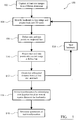
- Figure 1 shows a flow chart illustrating the image correction method 100 of the invention.
- Pre-operatively either immediately or some time before surgery, at least two images of the patient's body part are captured 102 from different directions by an imaging system.
- an imaging system By capturing at least two images from different directions of the same body part, three dimensional structural information about the body part can be obtained.
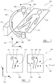
- FIG. 2 shows a schematic diagram illustrating a system 200 used to carry out the image capture step 102.
- An imaging system 202 in the form of a digital X-ray imaging system 202, includes an X-ray source 204 attached at a first end of a C-arm 206 and a digital X-ray image detector 208 at a second end of the C-arm.
- an analogue X-ray system can be used, and then the images from the X-ray films are digitised for processing.
- the C-arm is mounted on a housing 210 containing various electronics for controlling image capture and moving the C-arm about a circle as illustrated by double headed arrow 212.
- a patient 214 lies on a support surface 216, positioned so that the X-ray beam passes through the part of the patient being imaged, in the illustrated example, the patient's knee joint.
- An X-ray calibration phantom 218 is also located on the support surface adjacent the patient's knee so that the calibration phantom is also present in the captured images.
- X-ray calibration phantoms are generally known in the art and include a number of X-ray opaque fiducial markers having a known spatial arrangement, in terms of their relative positions and separations. The position of the X-ray source which captured an image including the fiducials of the phantom can be determined using geometry based on the appearance of the fiducials in the captured image in a manner generally understood in the art.
- a first X-ray image is captured with the X-ray source 204 and X-ray detector 208 in a first position, and then at least a second X-ray image is captured with the X-ray source 204' and X-ray detector 208' in a second position (as illustrated by dashed lines in Figure 2 ). Images from at least two different directions of the bone are captured, but the accuracy and reliability of the method can be improved by capturing images from more than two different directions.
- the arbitrary co-ordinate frame 220 for the imaging system is illustrated in Figure 2 . As can be seen, the C-arm pivots about the y-axis and two dimensional X-ray images are captured generally in the x-y plane.
- Figure 3 illustrates the of two radiographs 300 of the femoral head of a patient captured by the imaging system projected into the x-y plane 302.
- the first radiograph 304 was captured with the X-ray source in the first position and the second radiograph 306 was captured with the X-ray source in the second position.
- the first radiograph includes a first projection image of the femoral head 308 of the patient and the fiducials 310 of the calibration phantom 218.
- the second radiograph includes a second projection image of the femoral head 312 of the patient and the fiducials 314 of the calibration phantom 218.
- the point 318 marks the point in the x-y plane where the X-ray beam has orthogonal incidence on the imaging plane for the first image, and has co-ordinates (x 01 , y o1 ).
- the point 320 marks the point in the x-y plane where the X-ray beam has orthogonal incidence on the imaging plane for the second image, and has co-ordinates (x o2 , y o2 ), and may not actually fall in the captured image, as illustrated in Figure 3 .
- Also shown in Figure 3 are the positions of first and second anatomical landmark points 322 and 324, e.g. the centre of the femoral head and the tip of the greater trochanter, in the first image 304, and the positions of the same two anatomical landmark points 326, 328 in the second image 306.
- Figure 3 illustrates the scenario in which there has been no movement of the patient's body part between capture of the first and second images.
- the image plane does not rotate as the X-ray source is rotated about the y-axis. Rather the image plane simply translates in the x-y plane. From the positions of the fiducials 310, 314 in the images and the positions of the orthogonal points of incidence 318, 320 it is possible to back project for each image into the 3-D co-ordinate system to determine the position that the X-ray source must have been at in order to generate the image of the fiducials present in the captured image.
- any differences in the images of the bone must be due solely to the differences in the imaging geometry and the actual shape of the bone. Therefore, as the different imaging geometries can be determined from the fiducials, it is possible to use both images simultaneously to instantiate a 3-D statistical shape model of the bone for an accurate reconstruction of the 3-D shape of the bone.
- the position of the bone image 308 in the image 304 and the position of the bone image 312 in the image 306 is generally the same. That is there has been no shift in the position of the bone image between image captures. This means that certain movements of the bone have not occurred. However, if the bone has only translated in the x-direction between image captures, then it would not be possible to distinguish this movement of the bone within the images from the movement of the images themselves owing to rotation of the C-arm about the y-axis, which generally causes a translation of the imaging planes in the x-direction.
- Figure 4A shows a graphical representation of the imaging geometry 400 in the z-x plane
- Figure 4B shows corresponding captured first and second projected images 402 in the y-x plane, similar to those of Figure 3 , but omitting the fiducial points in the images and the positions of orthogonal incidence.
- the first image 404 was captured with the x-ray source in a first position 410 and the second image 406 with the x-ray source in a second position 408.
- Image 404 includes an image of the femur of the patient 412, and includes two anatomical landmarks, the centre of the femoral head 414 and the tip of the greater trochanter 416.
- the position of a number of anatomical landmarks in the captured bone image are identified, e.g . points 414 and 416.
- vectors include a leading unit element in order to facilitate the notation of matrix transformations for combined rotations and translations, i.e. using the homogeneous coordinate approach.
- the landmark point 416 in the image is projected back into 3D space to the position 410 of the X-ray source at step 104, as illustrated by line 418.
- the position of the X-ray source, 408, can be determined from the images of the fiducial points in the image 406, as described above.
- the maximum 420 and minimum positions 422 in 3D space are projected into the second image 406, and the points 424, 426 in the second image corresponding to the maximum and minimum positions define a line 428 in the second image.
- points 430 and 432 correspond to the same anatomical landmarks 414,416.
- the orthogonal distance 434 between the projected line 428 and the landmark is determined.
- the length of the orthogonal line 434 is normalised to length 1 for entering in a formula below. In this way, the scalar product of the normalised line with the vector pointing from the landmark to any point on the projected line yields the orthogonal distance.
- the normalised orthogonal line is referred to as "ortholine" in the formula below.
- return line 114 the above process is generally carried out for all n anatomical landmarks identified in the images at step 104.
- a transformation T 3D1-3D2 between the 3-D positions of bony landmarks for the first exposure and the second exposure is found that minimises the lengths of the orthogonal lines between all n landmark points in the second image and the corresponding projected lines, e.g. the length of orthogonal line 434 between line 428 and landmark 430, i.e.
- T 3 D 1 ⁇ 3 D 2 1 0 0 0 d x d y R ⁇ ⁇ ⁇ d z
- d is a displacement vector
- R is a rotation matrix with ⁇ , ⁇ , ⁇ the rotation angles around the x, y and z axes:
- R ⁇ cos ⁇ sin ⁇ 0 ⁇ sin ⁇ cos ⁇ 0 0 0 1 cos ⁇ 0 ⁇ sin ⁇ 0 1 0 sin ⁇ 0 cos ⁇ 1 0 0 0 cos ⁇ sin ⁇ 0 ⁇ sin ⁇ cos ⁇ sin ⁇ 0 ⁇ sin ⁇ cos ⁇
- the algorithm used for minimisation can be a standard algorithm for minimization, such as the Simplex algorithm.
- the resulting transformation parameters for the minimisation can be determined at step 118 and specify the transformation that will map the position of the imaged body part from the first exposure to the second exposure.
- patient body related motion artefacts can be removed from the captured image data so that the image data more accurately represents only the shape of the body part.
- the transformation parameters allow the true position of the X-ray source with respect to the bone when the second image was captured to be determined.
- the downward shift of the bone image in the second image 406 may be as a result of movement of the patient along the patient support in the y-direction between image captures.
- that patient motion artefact can effectively be included in the reconstruction of the imaging geometry, so that the significant differences between the bone images will reflect primarily the differences in the imaging geometry between acquisitions.
- the invention does not actually change the images themselves, but rather the imaging geometry reconstruction.
- Rotation about the x-axis has similar effects to a translation along the z-axis, but in practice a translation along the z-axis will be a very difficult movement for a patient to make and therefore unlikely to occur.
- Rotation about the z-axis will result in different sized landmark position changes in the second image depending on the position of the landmark. If the x coordinate of the landmark is close to the rotation axis then not much movement will be seen in the second image. If the x-coordinate of the landmark is further away from the rotation axis, then greater amounts of movement will be seen in the second image.
- a displacement along the z axis will be difficult to distinguish from a rotation around the x axis, but only one of those is likely to occur for a given bone structure to be imaged. Any displacement in the y axis, or rotation around x or z axes can be corrected for by this method.
- correction is applied to the recording of two X-rays from two different angles for creating a model of the proximal femur bone.
- the x-ray source is rotated around the body main axis for the second exposure.
- the parameters that can not be corrected are: lateral movement of the bone, vertical movement of the bone, and inward/outward rotation of the bone.
- the first two are unlikely to happen since the pelvis will rest firmly on the table during x-ray acquisition.
- Inward/outward rotation of the bone can be prevented by rotating inward before acquiring the x-ray (which is following a standard procedure), and fixing the leg in that rotation, e.g., at the feet.
- a flexion of the leg or an abduction are the most likely movement artefacts, both of which can be corrected using the described method.
- the number of landmarks that is needed for a successful correction depends on the application.
- the minimum number for correcting for the three degrees of freedom mentioned above is three landmarks.
- these landmarks could be: (I) the centre of the femoral head ; (ii) the medial portion of the tip of the greater trochanter; and (iii) the most proximal part of the lesser trochanter
- the transformation parameters are obtained at step 118.
- the first X-ray image is compared to a digitally reconstructed radiograph from the statistical shape model.
- the same motion artefact is applied during the projection, to reconstruct the actual imaging geometry as in the original X-ray capture of the second image.
- the invention is not limited to use with statistical shape models and can also be used in radiostereometric analysis (RSA) type methods to correct motion artefacts.
- RSA radiostereometric analysis
- the X-ray images do not need to be captured with the patient on a support.
- the X-ray images can be captured with the patient kneeling or standing.
- the X-ray images can be captured of any part of the anatomy that can be imaged by X-rays, or other imaging modalities, but is particularly suitable for bones and joints.
- the accuracy of the method can be increased if more landmarks are identified.
- the accuracy can also be increased by identifying landmarks using an automated image processing procedure. It is important, however, that the same landmark is projected on the two projection images. For example, this is not necessarily the case for bone contours. Depending on from where a bone is imaged, a different part of the bone surface may be prominent in the projection image.
- small implanted particles can be used that show in the projection image as bony landmarks. These particles can be automatically recognized using software that evaluates the images.
- the method of the invention can be embodied in an image processing system which has access to the data sets representing the digital images captured by the X-ray system.
- the image processing system can be provided as part of the X-ray imaging system or as a stand alone system or as part of another system, such as part of a computer assisted surgery system.
- the image processing system can be provided as part of a modelling system of a computer assisted surgery system and the image data and the transformation data generated by the method can be supplied to a statistical shape modelling method to generate a more accurate statistical shape model, based on the X-ray images and the true position of the bone relative to the imaging system when the images were captured.
- the image processing system can be implemented entirely in hardware, or as a combination of hardware and software.
Landscapes
- Engineering & Computer Science (AREA)
- Computer Vision & Pattern Recognition (AREA)
- Physics & Mathematics (AREA)
- General Physics & Mathematics (AREA)
- Theoretical Computer Science (AREA)
- Multimedia (AREA)
- Apparatus For Radiation Diagnosis (AREA)
- Image Processing (AREA)
- Image Analysis (AREA)
Description
- The present invention relates to image processing, and in particular to methods and apparatus for processing images to compensate for any movement of a subject between images.
- Various imaging technologies, whether analogue or digital, are widely used in medical applications to capture images of internal structures of a body and particularly bones. In some applications, it can be useful to capture multiple images of a body part. In some applications, it does not matter if the body part moves between image captures.
However, in other applications it can be important that the body part remains stationary between image captures. For example, in applications in which images of the same body part from different directions are required, it can be important that there is no movement of the body part between image captures, otherwise, it can be difficult to determine whether a feature in the image is a genuine feature of the body part or an artefact created by movement of the body part between image captures. - For example, multiple X-ray images of the same body part can be used to instantiate a statistical shape model of the body part. If there is movement of the body part between X-ray image captures, then the instantiated model may be less accurate, as it is trying to fit to an artefact in the image data set, rather than to the pure image data.
- Fiducials with a known geometry can be used so that the position of the body part relative to the fiducials can be determined from captured images including the fiducials. However, in the time that passes between the acquisition of two projection images, the subject may move with respect to the fiducials that are to be used to register the image into one coordinate system. This may occur when imaging soft tissues, e.g. the heart, or when imaging extremities like legs or arms, if the fiducials are not rigidly attached to the object of interest. For example, in pre-operative bone model calculation, the calibration object can sometimes not be attached rigidly to the body part (especially in obese patients, or for the pelvis, the femur, humerus, etc.).
- In the case of movement of a rigid body part, e.g. a bone, and few images, the motion artefact may not easily be recognized, and an incorrect reconstruction of the imaging system geometry may occur.
- US Patent application publication number
US 2005/0220264 A1 describes a technique in which projection images are corrected to nullify any motion. However, image correction often results in errors due to interpolation artefacts. -
US 2006/0133564 describes a method and apparatus for reducing image artefacts arising in image reconstruction for dynamic objects under going periodic motion, such as the heart. An X-ray C-arm is used to capture a plurality of projection X-ray images of the heart from different directions over multiple cycles of the heart. This provides X-ray image of the heart at the same phase of its cycle but form different directions. The images for the same phase of the cycle are combined to provide a reconstructed image and the reconstructed image can then be pre-processed by filtering to remove certain image artefacts caused by the heart being in motion while the individual images were capture. Feature based processing can be used to determine estimates of the motion of the heart between each of the phases of its cycle and the motion estimates are used to warp or adapt a reconstruction grid used at each view angle. The projection images are then reconstructed using the respective warped reconstruction grid for each view angle position to generate the motion corrected reconstructions of the heart. - "Prospective Motion Correction of X-Ray Images for Coronary Interventions", IEEE Transactions on Medical Imaging, Vol. 24, no. 4, 1st April 2005, pages 441-450, XP11129442 describes a system and method for prospective motion correction of X-ray imaging of the heart. A C-arm is used to capture X-ray images of the heart from multiple different directions. A 3D + t coronary model is reconstructed from biplane coronary angiogram obtained during free breathing. The motion of the 3D coronary model is projected onto the image planes and used to compute a dewarping function for motion correcting the images.
- Hence, it would be advantageous to be able to reduce the existence of artefacts in image data resulting from movement of a body part between image captures.
- According to a first aspect of the invention, there is provided a method for correcting motion artefacts in captured projection images of a bone of a subject caused by movement of the bone relative to the co-ordinate system of an imaging system between capture of the images of the bone by the imaging system, comprising: (i) obtaining a first image data set representing a first captured projection image of the bone for which the imaging system had a first geometry in the co-ordinate system; (ii) obtaining a second image data set representing a second captured projection image of the same bone for which the imaging system had a second geometry in the co-ordinate system, and in which the second captured projection image is from a different direction to the first captured projection image; (iii) identifying the position of at least a first anatomical landmark point of the bone in the first captured projection image from the first image data set; (iv) projecting the position of the first anatomical landmark point back as a ray in the 3D space of the co-ordinate system and defining maximum and minimum positions along the ray enclosing the image volume; (v) projecting the maximum and minimum positions of the at least first anatomical landmark point of the bone into the second captured projection image to define a line in the second captured projection image; (vi) determining the orthogonal distance between the line and the position of the same anatomical landmark point of the bone from the second image data set; and (vii) determining a transformation required to map the position of the same anatomical landmark point of the bone from the second image data set onto the projected position of the at least first anatomical landmark point of the bone by minimising the orthogonal distance, wherein the so determined transformation allows the true position of the bone relative to the imaging system when the second image was captured to be determined.
- Hence, the present invention is based on the approach of correcting the imaging geometry according to the changes in position of the body part detectable in the captured images. This leaves the images unchanged and hence does not introduce artefacts as can occur in approaches based on correcting the images themselves.
- Various minimisation algorithms can be used, such as the Simplex algorithm.
- A plurality of different anatomical landmark points can be used. For example, at least three different anatomical landmark points for a given body part can be used.
- Projecting the position of the at least first anatomical landmark point can comprise transforming the position of the first anatomical landmark point in the first image into the 3D co-ordinate system of the imaging system. Projecting the position can further comprise transforming from the 3D co-ordinate system of the imaging system into positions in the second image. Preferably, transformation matrices are used.
- Determining the transformation can include applying a parameterised transformation. The parameters can be varied during minimisation. The transformation can be applied using a transformation matrix.
- Angular rotations and/or translations can be parameterised. Preferably, three rotation angles and three translations are parameterised.
- The method can further comprise using the positions in the captured images of orthogonal incidence of an X-ray beam of the imaging system on an imaging plane to determine the positions of the anatomical landmark in the first and second images.
- The method can be applied to images captured by various types of imaging systems. The imaging system can be an X-ray imaging system, and preferably a digital X-ray imaging system. Such systems are particularly suitable for imaging bones.
- Preferably, the body part that was imaged includes at least a part, or the whole, of at least one joint of the subject's body. The body part can be a knee joint, ankle joint, hip joint, shoulder joint, spinal joint and similar.
- The method can further comprise instantiating a statistical shape model, using the first image data set, the second image data set and the transformation.
- The method can further comprise capturing the first image and the second image.
- A further aspect of the invention is a computer readable medium bearing computer program code executable by a data processing device to carry out the method aspect of the invention.
- A further aspect of the invention provides an image processing system for correcting motion artefacts in captured images of a bone of a subject caused by movement of the bone relative to the co-ordinate system of an imaging system between capture of the images by the imaging system according to independent claim 9.
- An embodiment of the invention will now be described, by way of example only, and with reference to the accompanying drawings, in which:
-
Figure 1 shows a flow chart illustrating an image correction method of the invention; -
Figure 2 shows a schematic perspective view of an X-ray imaging system capturing first and second images of a body part of a patient; -
Figure 3 shows a graphical representation of X-ray images of the same body part captured from different directions; -
Figure 4A shows a graphical representation of the imaging geometry during capture of the two images and illustrating part of the method ofFigure 1 ; andFigure 4B shows a graphical representation of the X-ray images ofFigure 4B . - Similar items in different Figures share common reference numerals unless indicated otherwise.
- Generally, the method of the invention uses features of projection images of bones that are taken from different angles. Bone landmarks in the projection images are identified. For a known imaging geometry, the position of a landmark identified in one projection image, translates into a trajectory in each of the other projection images. Herein, "imaging geometry" means the relative position of the source of the projection image with respect to the image plate for each of the projection images.
- If the same landmarks are identified in the second, and any further, images, then the method determines if the same landmarks lie on the trajectories that would be predicted by the imaging geometry. If not, then the imaging geometry was wrongly estimated. This can happen if a calibration object containing fiducials is not rigidly attached to the object of interest (e.g. a bone). Or, more generally, because the bone has moved with respect to the calibration object between two acquisitions.
- The invention is interested in the spatial relationship between two, or more, images of the same bone, taken from different angles. If the bone moved with respect to the calibration object, then the transformation that describes this movement should be introduced into the imaging geometry. The parameters of the transformation are varied until the correct transformation is found (i.e. the transformation that results in landmarks of the second image being as close as possible to the trajectories calculated from landmarks of the first image). Hence, the correct transformation is related to how the bone must have moved in order for the two images to be of the same bone captured from different directions. The transformation can then be used in other applications that require the two images to be available in a common frame of reference, e.g. for instantiating a statistical shape model.
- The method of the invention differs from photogrammetric approaches in that the projection image shows not points on a surface, but a projection through the structure. It therefore leaves fewer structures with a clear correspondence in three-dimensional space between the images.
- The method also differs from alignment procedures using Fourier transform methods. Those methods rely on the assumption that the imaging geometry is similar between the images (e.g. an orthogonal projection geometry). However, the centre beam of the cone beam projection will not necessarily be part of the image.
- Having described the method of the invention at high-level, a more detailed description will now be provided with reference to the Figures.
-
Figure 1 shows a flow chart illustrating theimage correction method 100 of the invention. Pre-operatively, either immediately or some time before surgery, at least two images of the patient's body part are captured 102 from different directions by an imaging system. By capturing at least two images from different directions of the same body part, three dimensional structural information about the body part can be obtained. -
Figure 2 shows a schematic diagram illustrating asystem 200 used to carry out theimage capture step 102. Animaging system 202, in the form of a digitalX-ray imaging system 202, includes anX-ray source 204 attached at a first end of a C-arm 206 and a digitalX-ray image detector 208 at a second end of the C-arm. In other embodiments, an analogue X-ray system can be used, and then the images from the X-ray films are digitised for processing. The C-arm is mounted on ahousing 210 containing various electronics for controlling image capture and moving the C-arm about a circle as illustrated by double headedarrow 212. - A
patient 214 lies on asupport surface 216, positioned so that the X-ray beam passes through the part of the patient being imaged, in the illustrated example, the patient's knee joint. AnX-ray calibration phantom 218 is also located on the support surface adjacent the patient's knee so that the calibration phantom is also present in the captured images. X-ray calibration phantoms are generally known in the art and include a number of X-ray opaque fiducial markers having a known spatial arrangement, in terms of their relative positions and separations. The position of the X-ray source which captured an image including the fiducials of the phantom can be determined using geometry based on the appearance of the fiducials in the captured image in a manner generally understood in the art. - As illustrated in
Figure 2 , a first X-ray image is captured with theX-ray source 204 andX-ray detector 208 in a first position, and then at least a second X-ray image is captured with the X-ray source 204' and X-ray detector 208' in a second position (as illustrated by dashed lines inFigure 2 ). Images from at least two different directions of the bone are captured, but the accuracy and reliability of the method can be improved by capturing images from more than two different directions. The arbitrary co-ordinateframe 220 for the imaging system is illustrated inFigure 2 . As can be seen, the C-arm pivots about the y-axis and two dimensional X-ray images are captured generally in the x-y plane. -
Figure 3 illustrates the of tworadiographs 300 of the femoral head of a patient captured by the imaging system projected into thex-y plane 302. Thefirst radiograph 304 was captured with the X-ray source in the first position and thesecond radiograph 306 was captured with the X-ray source in the second position. The first radiograph includes a first projection image of thefemoral head 308 of the patient and thefiducials 310 of thecalibration phantom 218. The second radiograph includes a second projection image of thefemoral head 312 of the patient and thefiducials 314 of thecalibration phantom 218. Thepoint 318 marks the point in the x-y plane where the X-ray beam has orthogonal incidence on the imaging plane for the first image, and has co-ordinates (x01, yo1). Thepoint 320 marks the point in the x-y plane where the X-ray beam has orthogonal incidence on the imaging plane for the second image, and has co-ordinates (xo2, yo2), and may not actually fall in the captured image, as illustrated inFigure 3 . Also shown inFigure 3 are the positions of first and second anatomical landmark points 322 and 324, e.g. the centre of the femoral head and the tip of the greater trochanter, in thefirst image 304, and the positions of the same two anatomical landmark points 326, 328 in thesecond image 306. -
Figure 3 illustrates the scenario in which there has been no movement of the patient's body part between capture of the first and second images. The image plane does not rotate as the X-ray source is rotated about the y-axis. Rather the image plane simply translates in the x-y plane. From the positions of thefiducials incidence reference frame 220 between images, then any differences in the images of the bone must be due solely to the differences in the imaging geometry and the actual shape of the bone. Therefore, as the different imaging geometries can be determined from the fiducials, it is possible to use both images simultaneously to instantiate a 3-D statistical shape model of the bone for an accurate reconstruction of the 3-D shape of the bone. - As illustrated in
Figure 3 , the position of thebone image 308 in theimage 304 and the position of thebone image 312 in theimage 306 is generally the same. That is there has been no shift in the position of the bone image between image captures. This means that certain movements of the bone have not occurred. However, if the bone has only translated in the x-direction between image captures, then it would not be possible to distinguish this movement of the bone within the images from the movement of the images themselves owing to rotation of the C-arm about the y-axis, which generally causes a translation of the imaging planes in the x-direction. -
Figure 4A shows a graphical representation of theimaging geometry 400 in the z-x plane, andFigure 4B shows corresponding captured first and second projectedimages 402 in the y-x plane, similar to those ofFigure 3 , but omitting the fiducial points in the images and the positions of orthogonal incidence. Thefirst image 404 was captured with the x-ray source in afirst position 410 and thesecond image 406 with the x-ray source in asecond position 408.Image 404 includes an image of the femur of thepatient 412, and includes two anatomical landmarks, the centre of thefemoral head 414 and the tip of thegreater trochanter 416. Atstep 104, the position of a number of anatomical landmarks in the captured bone image are identified, e.g.points - In the following formulae, vectors include a leading unit element in order to facilitate the notation of matrix transformations for combined rotations and translations, i.e. using the homogeneous coordinate approach.
- The position of the ith landmark on
image 1 is:
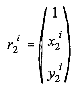
- The
landmark point 416 in the image is projected back into 3D space to theposition 410 of the X-ray source atstep 104, as illustrated byline 418. The position of the X-ray source, 408, can be determined from the images of the fiducial points in theimage 406, as described above. In practice, thepoint 416 in the first image is transformed into a common 3D co-ordinate system using the matrix:
- λ ∈ [0,1]
- and encodes the position on the
ray 418 from the point in the image to the x-ray source position. Thex-ray source 410 is considered to lie at point z = 0 on the z axis. The position of theimage plane 404 on the z axis, is denoted z0, and z1 and z2 are the heights enclosing the image volume of interest, as shown inFigure 4A , with z0 > z1 > z2. Atstep 106, maximum 420 and minimum 422 positions in 3D space along theline 418 are defined by setting λ to 0 and 1. - Then at
step 110 the maximum 420 andminimum positions 422 in 3D space are projected into thesecond image 406, and thepoints line 428 in the second image. In practice, the maximum andminimum positions 
- In the
second image 406, points 430 and 432 correspond to the same anatomical landmarks 414,416. Atstep 112 theorthogonal distance 434 between the projectedline 428 and the landmark is determined. The length of theorthogonal line 434 is normalised tolength 1 for entering in a formula below. In this way, the scalar product of the normalised line with the vector pointing from the landmark to any point on the projected line yields the orthogonal distance. The normalised orthogonal line is referred to as "ortholine" in the formula below. As illustrated byreturn line 114, the above process is generally carried out for all n anatomical landmarks identified in the images atstep 104. - Then at
step 116, a transformation T3D1-3D2 between the 3-D positions of bony landmarks for the first exposure and the second exposure is found that minimises the lengths of the orthogonal lines between all n landmark points in the second image and the corresponding projected lines, e.g. the length oforthogonal line 434 betweenline 428 andlandmark 430, i.e.


- The algorithm used for minimisation can be a standard algorithm for minimization, such as the Simplex algorithm. Hence, the resulting transformation parameters for the minimisation can be determined at
step 118 and specify the transformation that will map the position of the imaged body part from the first exposure to the second exposure. Hence, patient body related motion artefacts can be removed from the captured image data so that the image data more accurately represents only the shape of the body part. The transformation parameters allow the true position of the X-ray source with respect to the bone when the second image was captured to be determined. - For example, in
Figure 4B , the downward shift of the bone image in thesecond image 406 may be as a result of movement of the patient along the patient support in the y-direction between image captures. Using the transformation parameters, that patient motion artefact can effectively be included in the reconstruction of the imaging geometry, so that the significant differences between the bone images will reflect primarily the differences in the imaging geometry between acquisitions. The invention does not actually change the images themselves, but rather the imaging geometry reconstruction. - In general there are three rotations and three translations of the patient's body part that are possible. Assuming that the x-ray system is rotated around the y-axis before the second projection image, a translation in the x-direction cannot easily be identified as it is masked by the similar effect caused by the unknown positions of the landmarks on the back projection ray. Translations in the γ-direction will shift all landmarks up or down in the second image. Translations in the z-direction will increase or decrease spacing between landmarks. Rotations about the y-axis are difficult to detect as all landmarks will stay on the same line. Rotation about the x-axis has similar effects to a translation along the z-axis, but in practice a translation along the z-axis will be a very difficult movement for a patient to make and therefore unlikely to occur. Rotation about the z-axis will result in different sized landmark position changes in the second image depending on the position of the landmark. If the x coordinate of the landmark is close to the rotation axis then not much movement will be seen in the second image. If the x-coordinate of the landmark is further away from the rotation axis, then greater amounts of movement will be seen in the second image.
- Hence, displacements or rotations that happen in the same plane as the one affected by the rotation of the x-ray source will not be detected. For example, if the x-ray source rotates around the y axis, as illustrated in
Figure 1 , then a bone displacement along the x axis will be difficult to detect. Similarly, a bone rotation around the y axis will be difficult to detect. This is because a displacement that can be described by these parameters will result in a displacement of landmarks in the second image along the line of the projection of landmarks in the first image, with no component of that displacement perpendicular to that line. A displacement along the z axis will be difficult to distinguish from a rotation around the x axis, but only one of those is likely to occur for a given bone structure to be imaged. Any displacement in the y axis, or rotation around x or z axes can be corrected for by this method. - In the example application of the invention described above, correction is applied to the recording of two X-rays from two different angles for creating a model of the proximal femur bone. The x-ray source is rotated around the body main axis for the second exposure. For this case, the parameters that can not be corrected are: lateral movement of the bone, vertical movement of the bone, and inward/outward rotation of the bone. The first two are unlikely to happen since the pelvis will rest firmly on the table during x-ray acquisition. Inward/outward rotation of the bone can be prevented by rotating inward before acquiring the x-ray (which is following a standard procedure), and fixing the leg in that rotation, e.g., at the feet. In this situation, a flexion of the leg or an abduction are the most likely movement artefacts, both of which can be corrected using the described method.
- The number of landmarks that is needed for a successful correction depends on the application. The minimum number for correcting for the three degrees of freedom mentioned above is three landmarks. In the example of the proximal femur, these landmarks could be: (I) the centre of the femoral head ; (ii) the medial portion of the tip of the greater trochanter; and (iii) the most proximal part of the lesser trochanter
- If the X-ray images are to be used to instantiate a statistical shape model, then the transformation parameters are obtained at
step 118. The first X-ray image is compared to a digitally reconstructed radiograph from the statistical shape model. To create the second digitally reconstructed radiograph from the statistical shape model, the same motion artefact is applied during the projection, to reconstruct the actual imaging geometry as in the original X-ray capture of the second image. - The invention is not limited to use with statistical shape models and can also be used in radiostereometric analysis (RSA) type methods to correct motion artefacts.
- The X-ray images do not need to be captured with the patient on a support. For example, the X-ray images can be captured with the patient kneeling or standing. Further, the X-ray images can be captured of any part of the anatomy that can be imaged by X-rays, or other imaging modalities, but is particularly suitable for bones and joints.
- The accuracy of the method can be increased if more landmarks are identified. The accuracy can also be increased by identifying landmarks using an automated image processing procedure. It is important, however, that the same landmark is projected on the two projection images. For example, this is not necessarily the case for bone contours. Depending on from where a bone is imaged, a different part of the bone surface may be prominent in the projection image.
- In another embodiment small implanted particles can be used that show in the projection image as bony landmarks. These particles can be automatically recognized using software that evaluates the images.
- The method of the invention can be embodied in an image processing system which has access to the data sets representing the digital images captured by the X-ray system. The image processing system can be provided as part of the X-ray imaging system or as a stand alone system or as part of another system, such as part of a computer assisted surgery system. For example, the image processing system can be provided as part of a modelling system of a computer assisted surgery system and the image data and the transformation data generated by the method can be supplied to a statistical shape modelling method to generate a more accurate statistical shape model, based on the X-ray images and the true position of the bone relative to the imaging system when the images were captured. The image processing system can be implemented entirely in hardware, or as a combination of hardware and software.
- It will be appreciated that in the above description of the invention, reference has been made to various features of the images, such as a line in the image. However, it will be appreciated that there is no need for such features of the images to be generated and displayed. Rather all that is required is for such features to be represented by data, e.g. mathematically, for the invention to function and so the terms in the description and claims referring to such features should be construed accordingly.
Claims (9)
- A method (100) for correcting motion artefacts in captured projection images of a bone of a subject (214) caused by movement of the bone relative to the co-ordinate system (220) of an imaging system (202) between capture of the images of the bone by the imaging system (202), comprising:(i) obtaining (102) a first image data set representing a first captured projection image (404) of the bone for which the imaging system had a first geometry (410) in the co-ordinate system;(ii) obtaining (102) a second image data set representing a second captured projection image (406) of the same bone for which the imaging system had a second geometry (408) in the co-ordinate system, and in which the second captured projection image is from a different direction to the first captured projection image;(iii) identifying (104) the position (414, 416) of at least a first anatomical landmark point of the bone in the first captured projection image from the first image data set;(iv) projecting (104) the position of the first anatomical landmark point back as a ray (418) in the 3D space of the co-ordinate system and defining (106) maximum (420) and minimum (422) positions along the ray enclosing the image volume;(v) projecting (110) the maximum and minimum positions of the at least first anatomical landmark point of the bone into the second captured projection image (406) to define a line (428) in the second captured projection image;(vi) determining (112) the orthogonal distance (434) between the line (428) and the position (430) of the same anatomical landmark point of the bone from the second image data set; and(vii) determining (116) a transformation required to map the position of the same anatomical landmark point of the bone from the second image data set onto the projected position of the at least first anatomical landmark point of the bone by minimising the orthogonal distance, wherein the so determined transformation allows the true position of the bone relative to the imaging system when the second image was captured to be determined.
- The method as claimed in claim 1, wherein a plurality of different anatomical landmark points (414, 416, 430, 432) are used and wherein steps (iii) to (vi) are
carried out for each landmark (114) and step (vii) minimises the orthogonal distances for all the landmarks. - The method as claimed in claim 1, wherein determining the transformation (116) includes applying a parameterised transformation and the parameters are varied during minimisation.
- The method as claimed in claim 3, wherein three rotation angles and three translations are parameterised.
- The method as claimed in claim 1, and further comprising using the positions (318, 320) in the captured images of orthogonal incidence of an X-ray beam of the imaging system on an imaging plane to determine the positions of the anatomical landmark in the first and second images.
- The method as claimed in any preceding claim, wherein the imaging system (202) is an X-ray imaging system.
- The method as claimed in any preceding claim, and further comprising:instantiating a statistical shape model of the bone, using the first image data set, the second image data set and the transformation.
- A computer readable medium bearing computer program code executable by a data processing device to carry out the method of any of claims 1 to 7.
- An image processing system for correcting motion artefacts in captured projection images of a static bone of a subject caused by movement of the static bone relative to the co-ordinate system of an imaging system between capture of the images by the imaging system, the image processing system including:at least a first storage device storing a first image data set representing a first captured projection image of the bone when the imaging system had a first geometry in the co-ordinate system and a second image data set representing a second captured projection image of the same bone when the imaging system had a second geometry in the co-ordinate system, in which the second captured image is from a different direction to the first captured image; anda controller capable of carrying out the method of any of claims 1 to 7.
Applications Claiming Priority (2)
| Application Number | Priority Date | Filing Date | Title |
|---|---|---|---|
| GBGB0714940.4A GB0714940D0 (en) | 2007-08-01 | 2007-08-01 | Image processing |
| PCT/IB2008/002569 WO2009016509A2 (en) | 2007-08-01 | 2008-07-30 | Image processing of motion artefacts by landmark tracking |
Publications (2)
| Publication Number | Publication Date |
|---|---|
| EP2206085A2 EP2206085A2 (en) | 2010-07-14 |
| EP2206085B1 true EP2206085B1 (en) | 2017-01-11 |
Family
ID=38529083
Family Applications (1)
| Application Number | Title | Priority Date | Filing Date |
|---|---|---|---|
| EP08826771.1A Active EP2206085B1 (en) | 2007-08-01 | 2008-07-30 | Correction of motion artefacts by landmark tracking |
Country Status (8)
| Country | Link |
|---|---|
| US (1) | US8391580B2 (en) |
| EP (1) | EP2206085B1 (en) |
| JP (1) | JP5547070B2 (en) |
| CN (1) | CN101809620B (en) |
| AU (1) | AU2008281432B2 (en) |
| CA (1) | CA2695164C (en) |
| GB (1) | GB0714940D0 (en) |
| WO (1) | WO2009016509A2 (en) |
Families Citing this family (15)
| Publication number | Priority date | Publication date | Assignee | Title |
|---|---|---|---|---|
| JP5328979B2 (en) * | 2009-05-12 | 2013-10-30 | トヨタ自動車株式会社 | Object recognition method, object recognition device, autonomous mobile robot |
| US9826942B2 (en) | 2009-11-25 | 2017-11-28 | Dental Imaging Technologies Corporation | Correcting and reconstructing x-ray images using patient motion vectors extracted from marker positions in x-ray images |
| US9082182B2 (en) | 2009-11-25 | 2015-07-14 | Dental Imaging Technologies Corporation | Extracting patient motion vectors from marker positions in x-ray images |
| US9082177B2 (en) | 2009-11-25 | 2015-07-14 | Dental Imaging Technologies Corporation | Method for tracking X-ray markers in serial CT projection images |
| US9082036B2 (en) | 2009-11-25 | 2015-07-14 | Dental Imaging Technologies Corporation | Method for accurate sub-pixel localization of markers on X-ray images |
| US9020235B2 (en) * | 2010-05-21 | 2015-04-28 | Siemens Medical Solutions Usa, Inc. | Systems and methods for viewing and analyzing anatomical structures |
| US8488862B2 (en) * | 2010-06-09 | 2013-07-16 | Siemens Medical Solutions Usa, Inc. | Characterization of source trajectory for radiotherapy |
| US8675939B2 (en) | 2010-07-13 | 2014-03-18 | Stryker Leibinger Gmbh & Co. Kg | Registration of anatomical data sets |
| US20120078088A1 (en) * | 2010-09-28 | 2012-03-29 | Point of Contact, LLC. | Medical image projection and tracking system |
| EP2518690A1 (en) * | 2011-04-28 | 2012-10-31 | Koninklijke Philips Electronics N.V. | Medical image processing system and method |
| CN103315739B (en) * | 2013-05-22 | 2015-08-19 | 华东师范大学 | The nuclear magnetic resonance image method and system of motion artifacts is exempted based on Dynamic Tracing Technology |
| GB201502877D0 (en) * | 2015-02-20 | 2015-04-08 | Cydar Ltd | Digital image remapping |
| EP3421086B1 (en) * | 2017-06-28 | 2020-01-15 | OptiNav Sp. z o.o. | Determination of geometrical information about a medical treatment arrangement comprising a rotatable treatment radiation source unit |
| EP4014911B1 (en) * | 2020-12-21 | 2023-10-04 | Metamorphosis GmbH | Artificial-intelligence-based detection of invisible anatomical structures in 2d x-ray images |
| US12100174B2 (en) * | 2021-07-26 | 2024-09-24 | GE Precision Healthcare LLC | Methods and system for dynamically annotating medical images |
Family Cites Families (14)
| Publication number | Priority date | Publication date | Assignee | Title |
|---|---|---|---|---|
| US5799055A (en) * | 1996-05-15 | 1998-08-25 | Northwestern University | Apparatus and method for planning a stereotactic surgical procedure using coordinated fluoroscopy |
| WO1998047426A1 (en) * | 1997-04-21 | 1998-10-29 | Virtual Technologies, Inc. | Goniometer-based body-tracking device and method |
| DE19826994C1 (en) * | 1998-06-19 | 1999-11-25 | Forschungszentrum Juelich Gmbh | Image generation method for nuclear spin tomography |
| US7239908B1 (en) * | 1998-09-14 | 2007-07-03 | The Board Of Trustees Of The Leland Stanford Junior University | Assessing the condition of a joint and devising treatment |
| AU1122401A (en) * | 1999-11-01 | 2001-05-14 | Arthrovision, Inc. | Evaluating disease progression using magnetic resonance imaging |
| EP1322224B1 (en) * | 2000-09-14 | 2008-11-05 | The Board Of Trustees Of The Leland Stanford Junior University | Assessing condition of a joint and cartilage loss |
| GB2390792B (en) * | 2002-07-08 | 2005-08-31 | Vision Rt Ltd | Image processing system for use with a patient positioning device |
| DE102004016586A1 (en) | 2004-03-31 | 2005-11-03 | Siemens Ag | Image reconstruction device for an X-ray device and method for local 3D reconstruction of an object region |
| JP4438053B2 (en) | 2004-05-11 | 2010-03-24 | キヤノン株式会社 | Radiation imaging apparatus, image processing method, and computer program |
| GB2416101A (en) | 2004-07-06 | 2006-01-11 | Elekta Ab | Imaging internal structures and correcting for motion artifacts |
| US7782998B2 (en) * | 2004-12-21 | 2010-08-24 | General Electric Company | Method and apparatus for correcting motion in image reconstruction |
| JP2006175057A (en) * | 2004-12-22 | 2006-07-06 | Fuji Photo Film Co Ltd | Image processing apparatus, and its program and method |
| JP5639764B2 (en) * | 2007-03-08 | 2014-12-10 | シンク−アールエックス,リミティド | Imaging and tools for use with moving organs |
| WO2010058398A2 (en) * | 2007-03-08 | 2010-05-27 | Sync-Rx, Ltd. | Image processing and tool actuation for medical procedures |
-
2007
- 2007-08-01 GB GBGB0714940.4A patent/GB0714940D0/en not_active Ceased
-
2008
- 2008-07-30 CA CA2695164A patent/CA2695164C/en not_active Expired - Fee Related
- 2008-07-30 CN CN200880109688XA patent/CN101809620B/en not_active Expired - Fee Related
- 2008-07-30 JP JP2010518775A patent/JP5547070B2/en active Active
- 2008-07-30 US US12/671,662 patent/US8391580B2/en active Active
- 2008-07-30 AU AU2008281432A patent/AU2008281432B2/en not_active Ceased
- 2008-07-30 WO PCT/IB2008/002569 patent/WO2009016509A2/en not_active Ceased
- 2008-07-30 EP EP08826771.1A patent/EP2206085B1/en active Active
Also Published As
| Publication number | Publication date |
|---|---|
| US20110249882A1 (en) | 2011-10-13 |
| JP5547070B2 (en) | 2014-07-09 |
| CA2695164C (en) | 2016-12-20 |
| AU2008281432A1 (en) | 2009-02-05 |
| WO2009016509A3 (en) | 2009-06-04 |
| CA2695164A1 (en) | 2009-02-05 |
| US8391580B2 (en) | 2013-03-05 |
| CN101809620A (en) | 2010-08-18 |
| AU2008281432B2 (en) | 2012-10-18 |
| WO2009016509A2 (en) | 2009-02-05 |
| JP2010535051A (en) | 2010-11-18 |
| EP2206085A2 (en) | 2010-07-14 |
| GB0714940D0 (en) | 2007-09-12 |
| CN101809620B (en) | 2013-03-13 |
Similar Documents
| Publication | Publication Date | Title |
|---|---|---|
| US8391580B2 (en) | Image processing | |
| TWI836493B (en) | Method and navigation system for registering two-dimensional image data set with three-dimensional image data set of body of interest | |
| US11393110B2 (en) | Spatial registration of tracking system with an image using two-dimensional image projections | |
| US10426414B2 (en) | System for tracking an ultrasonic probe in a body part | |
| Penney et al. | Validation of a two‐to three‐dimensional registration algorithm for aligning preoperative CT images and intraoperative fluoroscopy images | |
| Guéziec et al. | Anatomy-based registration of CT-scan and intraoperative X-ray images for guiding a surgical robot | |
| JP5134957B2 (en) | Dynamic tracking of moving targets | |
| US6484049B1 (en) | Fluoroscopic tracking and visualization system | |
| US20190000564A1 (en) | System and method for medical imaging | |
| US20030130576A1 (en) | Fluoroscopic tracking and visualization system | |
| US20240320829A1 (en) | Correcting motion-related distortions in radiographic scans | |
| US20080300478A1 (en) | System and method for displaying real-time state of imaged anatomy during a surgical procedure | |
| US20030073901A1 (en) | Navigational guidance via computer-assisted fluoroscopic imaging | |
| WO2002000103A2 (en) | Method and apparatus for tracking a medical instrument based on image registration | |
| De Bruin et al. | Image-based RSA: Roentgen stereophotogrammetric analysis based on 2D–3D image registration | |
| Youn et al. | Iterative approach for 3D reconstruction of the femur from un-calibrated 2D radiographic images | |
| Abe et al. | Analysis of forearm rotational motion using biplane fluoroscopic intensity-based 2D–3D matching | |
| Wang et al. | Parallax-free long bone X-ray image stitching | |
| Gueziec | Assessing the registration of CT-scan data to intraoperative x rays by fusing x rays and preoperative information | |
| Yamazaki et al. | Development of three-dimensional kinematic analysis system for artificial knee implants using X-ray fluoroscopic imaging | |
| WO2026004090A1 (en) | Medical device, image processing method, computer program, and computer program product |
Legal Events
| Date | Code | Title | Description |
|---|---|---|---|
| PUAI | Public reference made under article 153(3) epc to a published international application that has entered the european phase |
Free format text: ORIGINAL CODE: 0009012 |
|
| 17P | Request for examination filed |
Effective date: 20100219 |
|
| AK | Designated contracting states |
Kind code of ref document: A2 Designated state(s): AT BE BG CH CY CZ DE DK EE ES FI FR GB GR HR HU IE IS IT LI LT LU LV MC MT NL NO PL PT RO SE SI SK TR |
|
| AX | Request for extension of the european patent |
Extension state: AL BA MK RS |
|
| 17Q | First examination report despatched |
Effective date: 20110523 |
|
| DAX | Request for extension of the european patent (deleted) | ||
| GRAP | Despatch of communication of intention to grant a patent |
Free format text: ORIGINAL CODE: EPIDOSNIGR1 |
|
| INTG | Intention to grant announced |
Effective date: 20160722 |
|
| GRAS | Grant fee paid |
Free format text: ORIGINAL CODE: EPIDOSNIGR3 |
|
| STAA | Information on the status of an ep patent application or granted ep patent |
Free format text: STATUS: GRANT OF PATENT IS INTENDED |
|
| GRAA | (expected) grant |
Free format text: ORIGINAL CODE: 0009210 |
|
| STAA | Information on the status of an ep patent application or granted ep patent |
Free format text: STATUS: THE PATENT HAS BEEN GRANTED |
|
| RAP1 | Party data changed (applicant data changed or rights of an application transferred) |
Owner name: JOHNSON & JOHNSON MEDICAL GMBH |
|
| AK | Designated contracting states |
Kind code of ref document: B1 Designated state(s): AT BE BG CH CY CZ DE DK EE ES FI FR GB GR HR HU IE IS IT LI LT LU LV MC MT NL NO PL PT RO SE SI SK TR |
|
| REG | Reference to a national code |
Ref country code: GB Ref legal event code: FG4D |
|
| REG | Reference to a national code |
Ref country code: CH Ref legal event code: EP |
|
| REG | Reference to a national code |
Ref country code: AT Ref legal event code: REF Ref document number: 861888 Country of ref document: AT Kind code of ref document: T Effective date: 20170115 |
|
| REG | Reference to a national code |
Ref country code: IE Ref legal event code: FG4D |
|
| REG | Reference to a national code |
Ref country code: DE Ref legal event code: R096 Ref document number: 602008048380 Country of ref document: DE |
|
| REG | Reference to a national code |
Ref country code: CH Ref legal event code: NV Representative=s name: E. BLUM AND CO. AG PATENT- UND MARKENANWAELTE , CH |
|
| REG | Reference to a national code |
Ref country code: LT Ref legal event code: MG4D |
|
| REG | Reference to a national code |
Ref country code: NL Ref legal event code: MP Effective date: 20170111 |
|
| REG | Reference to a national code |
Ref country code: FR Ref legal event code: PLFP Year of fee payment: 10 |
|
| REG | Reference to a national code |
Ref country code: AT Ref legal event code: MK05 Ref document number: 861888 Country of ref document: AT Kind code of ref document: T Effective date: 20170111 |
|
| PG25 | Lapsed in a contracting state [announced via postgrant information from national office to epo] |
Ref country code: NL Free format text: LAPSE BECAUSE OF FAILURE TO SUBMIT A TRANSLATION OF THE DESCRIPTION OR TO PAY THE FEE WITHIN THE PRESCRIBED TIME-LIMIT Effective date: 20170111 |
|
| PG25 | Lapsed in a contracting state [announced via postgrant information from national office to epo] |
Ref country code: FI Free format text: LAPSE BECAUSE OF FAILURE TO SUBMIT A TRANSLATION OF THE DESCRIPTION OR TO PAY THE FEE WITHIN THE PRESCRIBED TIME-LIMIT Effective date: 20170111 Ref country code: GR Free format text: LAPSE BECAUSE OF FAILURE TO SUBMIT A TRANSLATION OF THE DESCRIPTION OR TO PAY THE FEE WITHIN THE PRESCRIBED TIME-LIMIT Effective date: 20170412 Ref country code: IS Free format text: LAPSE BECAUSE OF FAILURE TO SUBMIT A TRANSLATION OF THE DESCRIPTION OR TO PAY THE FEE WITHIN THE PRESCRIBED TIME-LIMIT Effective date: 20170511 Ref country code: HR Free format text: LAPSE BECAUSE OF FAILURE TO SUBMIT A TRANSLATION OF THE DESCRIPTION OR TO PAY THE FEE WITHIN THE PRESCRIBED TIME-LIMIT Effective date: 20170111 Ref country code: NO Free format text: LAPSE BECAUSE OF FAILURE TO SUBMIT A TRANSLATION OF THE DESCRIPTION OR TO PAY THE FEE WITHIN THE PRESCRIBED TIME-LIMIT Effective date: 20170411 Ref country code: LT Free format text: LAPSE BECAUSE OF FAILURE TO SUBMIT A TRANSLATION OF THE DESCRIPTION OR TO PAY THE FEE WITHIN THE PRESCRIBED TIME-LIMIT Effective date: 20170111 |
|
| PG25 | Lapsed in a contracting state [announced via postgrant information from national office to epo] |
Ref country code: SE Free format text: LAPSE BECAUSE OF FAILURE TO SUBMIT A TRANSLATION OF THE DESCRIPTION OR TO PAY THE FEE WITHIN THE PRESCRIBED TIME-LIMIT Effective date: 20170111 Ref country code: AT Free format text: LAPSE BECAUSE OF FAILURE TO SUBMIT A TRANSLATION OF THE DESCRIPTION OR TO PAY THE FEE WITHIN THE PRESCRIBED TIME-LIMIT Effective date: 20170111 Ref country code: BG Free format text: LAPSE BECAUSE OF FAILURE TO SUBMIT A TRANSLATION OF THE DESCRIPTION OR TO PAY THE FEE WITHIN THE PRESCRIBED TIME-LIMIT Effective date: 20170411 Ref country code: LV Free format text: LAPSE BECAUSE OF FAILURE TO SUBMIT A TRANSLATION OF THE DESCRIPTION OR TO PAY THE FEE WITHIN THE PRESCRIBED TIME-LIMIT Effective date: 20170111 Ref country code: PT Free format text: LAPSE BECAUSE OF FAILURE TO SUBMIT A TRANSLATION OF THE DESCRIPTION OR TO PAY THE FEE WITHIN THE PRESCRIBED TIME-LIMIT Effective date: 20170511 Ref country code: ES Free format text: LAPSE BECAUSE OF FAILURE TO SUBMIT A TRANSLATION OF THE DESCRIPTION OR TO PAY THE FEE WITHIN THE PRESCRIBED TIME-LIMIT Effective date: 20170111 Ref country code: PL Free format text: LAPSE BECAUSE OF FAILURE TO SUBMIT A TRANSLATION OF THE DESCRIPTION OR TO PAY THE FEE WITHIN THE PRESCRIBED TIME-LIMIT Effective date: 20170111 |
|
| REG | Reference to a national code |
Ref country code: DE Ref legal event code: R097 Ref document number: 602008048380 Country of ref document: DE |
|
| PG25 | Lapsed in a contracting state [announced via postgrant information from national office to epo] |
Ref country code: SK Free format text: LAPSE BECAUSE OF FAILURE TO SUBMIT A TRANSLATION OF THE DESCRIPTION OR TO PAY THE FEE WITHIN THE PRESCRIBED TIME-LIMIT Effective date: 20170111 Ref country code: CZ Free format text: LAPSE BECAUSE OF FAILURE TO SUBMIT A TRANSLATION OF THE DESCRIPTION OR TO PAY THE FEE WITHIN THE PRESCRIBED TIME-LIMIT Effective date: 20170111 Ref country code: RO Free format text: LAPSE BECAUSE OF FAILURE TO SUBMIT A TRANSLATION OF THE DESCRIPTION OR TO PAY THE FEE WITHIN THE PRESCRIBED TIME-LIMIT Effective date: 20170111 Ref country code: EE Free format text: LAPSE BECAUSE OF FAILURE TO SUBMIT A TRANSLATION OF THE DESCRIPTION OR TO PAY THE FEE WITHIN THE PRESCRIBED TIME-LIMIT Effective date: 20170111 |
|
| PLBE | No opposition filed within time limit |
Free format text: ORIGINAL CODE: 0009261 |
|
| STAA | Information on the status of an ep patent application or granted ep patent |
Free format text: STATUS: NO OPPOSITION FILED WITHIN TIME LIMIT |
|
| PG25 | Lapsed in a contracting state [announced via postgrant information from national office to epo] |
Ref country code: DK Free format text: LAPSE BECAUSE OF FAILURE TO SUBMIT A TRANSLATION OF THE DESCRIPTION OR TO PAY THE FEE WITHIN THE PRESCRIBED TIME-LIMIT Effective date: 20170111 |
|
| 26N | No opposition filed |
Effective date: 20171012 |
|
| PG25 | Lapsed in a contracting state [announced via postgrant information from national office to epo] |
Ref country code: SI Free format text: LAPSE BECAUSE OF FAILURE TO SUBMIT A TRANSLATION OF THE DESCRIPTION OR TO PAY THE FEE WITHIN THE PRESCRIBED TIME-LIMIT Effective date: 20170111 |
|
| REG | Reference to a national code |
Ref country code: FR Ref legal event code: PLFP Year of fee payment: 11 |
|
| PG25 | Lapsed in a contracting state [announced via postgrant information from national office to epo] |
Ref country code: LU Free format text: LAPSE BECAUSE OF NON-PAYMENT OF DUE FEES Effective date: 20170730 |
|
| PG25 | Lapsed in a contracting state [announced via postgrant information from national office to epo] |
Ref country code: MT Free format text: LAPSE BECAUSE OF NON-PAYMENT OF DUE FEES Effective date: 20170730 |
|
| PG25 | Lapsed in a contracting state [announced via postgrant information from national office to epo] |
Ref country code: MC Free format text: LAPSE BECAUSE OF FAILURE TO SUBMIT A TRANSLATION OF THE DESCRIPTION OR TO PAY THE FEE WITHIN THE PRESCRIBED TIME-LIMIT Effective date: 20170111 Ref country code: HU Free format text: LAPSE BECAUSE OF FAILURE TO SUBMIT A TRANSLATION OF THE DESCRIPTION OR TO PAY THE FEE WITHIN THE PRESCRIBED TIME-LIMIT; INVALID AB INITIO Effective date: 20080730 |
|
| PG25 | Lapsed in a contracting state [announced via postgrant information from national office to epo] |
Ref country code: CY Free format text: LAPSE BECAUSE OF NON-PAYMENT OF DUE FEES Effective date: 20170111 |
|
| PG25 | Lapsed in a contracting state [announced via postgrant information from national office to epo] |
Ref country code: TR Free format text: LAPSE BECAUSE OF FAILURE TO SUBMIT A TRANSLATION OF THE DESCRIPTION OR TO PAY THE FEE WITHIN THE PRESCRIBED TIME-LIMIT Effective date: 20170111 |
|
| PGFP | Annual fee paid to national office [announced via postgrant information from national office to epo] |
Ref country code: IT Payment date: 20210610 Year of fee payment: 14 |
|
| PGFP | Annual fee paid to national office [announced via postgrant information from national office to epo] |
Ref country code: BE Payment date: 20210617 Year of fee payment: 14 |
|
| PGFP | Annual fee paid to national office [announced via postgrant information from national office to epo] |
Ref country code: DE Payment date: 20210630 Year of fee payment: 14 |
|
| REG | Reference to a national code |
Ref country code: DE Ref legal event code: R119 Ref document number: 602008048380 Country of ref document: DE |
|
| REG | Reference to a national code |
Ref country code: BE Ref legal event code: MM Effective date: 20220731 |
|
| PG25 | Lapsed in a contracting state [announced via postgrant information from national office to epo] |
Ref country code: DE Free format text: LAPSE BECAUSE OF NON-PAYMENT OF DUE FEES Effective date: 20230201 Ref country code: BE Free format text: LAPSE BECAUSE OF NON-PAYMENT OF DUE FEES Effective date: 20220731 |
|
| PG25 | Lapsed in a contracting state [announced via postgrant information from national office to epo] |
Ref country code: IT Free format text: LAPSE BECAUSE OF NON-PAYMENT OF DUE FEES Effective date: 20220730 |
|
| PGFP | Annual fee paid to national office [announced via postgrant information from national office to epo] |
Ref country code: GB Payment date: 20250605 Year of fee payment: 18 |
|
| PGFP | Annual fee paid to national office [announced via postgrant information from national office to epo] |
Ref country code: FR Payment date: 20250610 Year of fee payment: 18 |
|
| PGFP | Annual fee paid to national office [announced via postgrant information from national office to epo] |
Ref country code: IE Payment date: 20250610 Year of fee payment: 18 |
|
| PGFP | Annual fee paid to national office [announced via postgrant information from national office to epo] |
Ref country code: CH Payment date: 20250801 Year of fee payment: 18 |