EP2205510B1 - High speed selective can sorter - Google Patents
High speed selective can sorter Download PDFInfo
- Publication number
- EP2205510B1 EP2205510B1 EP08832913A EP08832913A EP2205510B1 EP 2205510 B1 EP2205510 B1 EP 2205510B1 EP 08832913 A EP08832913 A EP 08832913A EP 08832913 A EP08832913 A EP 08832913A EP 2205510 B1 EP2205510 B1 EP 2205510B1
- Authority
- EP
- European Patent Office
- Prior art keywords
- starwheel
- primary
- cans
- sorter
- vacuum
- Prior art date
- Legal status (The legal status is an assumption and is not a legal conclusion. Google has not performed a legal analysis and makes no representation as to the accuracy of the status listed.)
- Active
Links
Images


Classifications
-
- B—PERFORMING OPERATIONS; TRANSPORTING
- B21—MECHANICAL METAL-WORKING WITHOUT ESSENTIALLY REMOVING MATERIAL; PUNCHING METAL
- B21D—WORKING OR PROCESSING OF SHEET METAL OR METAL TUBES, RODS OR PROFILES WITHOUT ESSENTIALLY REMOVING MATERIAL; PUNCHING METAL
- B21D43/00—Feeding, positioning or storing devices combined with, or arranged in, or specially adapted for use in connection with, apparatus for working or processing sheet metal, metal tubes or metal profiles; Associations therewith of cutting devices
-
- B—PERFORMING OPERATIONS; TRANSPORTING
- B65—CONVEYING; PACKING; STORING; HANDLING THIN OR FILAMENTARY MATERIAL
- B65G—TRANSPORT OR STORAGE DEVICES, e.g. CONVEYORS FOR LOADING OR TIPPING, SHOP CONVEYOR SYSTEMS OR PNEUMATIC TUBE CONVEYORS
- B65G47/00—Article or material-handling devices associated with conveyors; Methods employing such devices
- B65G47/34—Devices for discharging articles or materials from conveyor
- B65G47/46—Devices for discharging articles or materials from conveyor and distributing, e.g. automatically, to desired points
- B65G47/51—Devices for discharging articles or materials from conveyor and distributing, e.g. automatically, to desired points according to unprogrammed signals, e.g. influenced by supply situation at destination
- B65G47/5104—Devices for discharging articles or materials from conveyor and distributing, e.g. automatically, to desired points according to unprogrammed signals, e.g. influenced by supply situation at destination for articles
- B65G47/515—First In-Last Out systems [FILO]; Last In-First Out systems [LIFO]
- B65G47/5154—First In-Last Out systems [FILO]; Last In-First Out systems [LIFO] using endless conveyors
-
- B—PERFORMING OPERATIONS; TRANSPORTING
- B65—CONVEYING; PACKING; STORING; HANDLING THIN OR FILAMENTARY MATERIAL
- B65G—TRANSPORT OR STORAGE DEVICES, e.g. CONVEYORS FOR LOADING OR TIPPING, SHOP CONVEYOR SYSTEMS OR PNEUMATIC TUBE CONVEYORS
- B65G47/00—Article or material-handling devices associated with conveyors; Methods employing such devices
- B65G47/74—Feeding, transfer, or discharging devices of particular kinds or types
- B65G47/84—Star-shaped wheels or devices having endless travelling belts or chains, the wheels or devices being equipped with article-engaging elements
- B65G47/846—Star-shaped wheels or wheels equipped with article-engaging elements
- B65G47/848—Star-shaped wheels or wheels equipped with article-engaging elements the article-engaging elements being suction or magnetic means
-
- B—PERFORMING OPERATIONS; TRANSPORTING
- B65—CONVEYING; PACKING; STORING; HANDLING THIN OR FILAMENTARY MATERIAL
- B65G—TRANSPORT OR STORAGE DEVICES, e.g. CONVEYORS FOR LOADING OR TIPPING, SHOP CONVEYOR SYSTEMS OR PNEUMATIC TUBE CONVEYORS
- B65G2201/00—Indexing codes relating to handling devices, e.g. conveyors, characterised by the type of product or load being conveyed or handled
- B65G2201/02—Articles
- B65G2201/0235—Containers
- B65G2201/0252—Cans
Definitions
- Belvac's necking system machinery As a manufacturer of high-speed rotational equipment, Belvac's necking system machinery has the ability to process containers at speeds in excess of 3000 containers/minute (@ 250 RPM). It is required of the container maker to periodically "sample” finished containers from the machine for quality assurance (QA) purposes, to ensure product specifications are maintained, and containers such as cans or bottles are obtained without processing damage (dents, scuffing etc). It is common for the container maker to stop the machine and remove a sequential series of containers equivalent to the number of processing stations per turret, or multiples thereof. The sequence relative to the station number is important: if quality assurance determines an adjustment is necessary, the specific station (or stations) where the adjustment is needed must be known. Because of the need to relate to a specific station, sample containers cannot be retrieved from conveyance downstream of the machine.
- DE 29 13 702 A1 describes a container machine including a control piston for transferring a container between first and second starwheels.
- a container machine comprising: an exit track for cans; a primary starwheel holding processed cans and moving the processed cans along a pitch line path toward the exit track; a sorter starwheel positioned adjacent to the primary starwheel and driven in phase synchronization with the primary starwheel; a sorter track for providing a path for cans held by the sorter starwheel; a can diverter mechanism to divert at least a selected one of the processed cans on the primary starwheel to a pocket of the sorter starwheel, the diverter mechanism including either a compressed air jet nozzle internal to a vacuum manifold, where the vacuum manifold communicates with each pocket of the primary starwheel, or a pair of blow-off nozzles, one on each side of the primary starwheel at a transfer area; and a timing device for causing the can diverter mechanism to operate while the primary starwheel is rotating at least at fifty percent of can production speed, or at least at ninety percent of the can production speed, or at least at can production speed.
- a minimum design gap to effect transfer of the cans without damage is provided between a pitch centerline of the primary starwheel and a pitch centerline of the sorter starwheel.
- an outer guide is provided in proximity to a dome end of the can and an outer guide in proximity to an open end of the can, the outer guide disposed to inhibit movement along an axis of the can.
- the timing device is programmable to eject a sequence of cans from a same pocket of the primary starwheel.
- the timing device is programmable to eject a sequence of cans from a plurality of pocket of the primary starwheel.
- an ink printer is provided for depositing in synchronization with the timing device an identification marking indicating a station number of origin.
- a tangential velocity of the sorter starwheel is substantially the same as a tangential velocity of the primary starwheel.
- the can production speed is approximately 3000 cans/minute.
- selected cans have been designated as rejects
- the timing device further comprises logic for transferring the reject cans to the sorter starwheel.
- an ink printer is provided for depositing in synchronization with the timing device an identification marking indicating a reject designation.
- the diverter mechanism is programmed to operate at a production speed up to at least 250 revolutions per minute.
- the primary starwheel is a transfer starwheel.
- a method for selecting and removing sample containers from a container machine comprising: holding by a primary starwheel processed cans and moving the processed cans along a pitch line path to toward an exit track; removing selected cans, using either a compressed air jet nozzle internal to a vacuum manifold, where the vacuum manifold communicates with each pocket of the primary starwheel, or a pair of blow-off nozzles, one on each side of the primary starwheel at a transfer area, from the primary starwheel prior to the exit track while the primary starwheel is rotating at least at fifty percent of can production speed or at least at can production speed; and placing the selected cans after removal on to a sorter track.
- a step is provided of driving a sorter vacuum starwheel positioned adjacent to the primary starwheel in phase synchronization with the primary starwheel; and wherein the removing step removes the selected cans to the sorter vacuum starwheel.
- the removing step comprises breaking a vacuum hold on at least a selected one of the cans on the primary starwheel and ejecting the selected one of the cans.
- the breaking vacuum step comprises directing a jet of a gas at the selected container with a timing designed to remove the container at a predetermined position.
- the removing step comprises breaking a magnetic hold on at least a selected one of the cans on the primary starwheel and ejecting the selected one of the cans.
- the removing step comprises electronically programming to automatically eject a sequence of cans from a same pocket of the primary starwheel.
- the removing step comprises electronically programming to automatically eject a sequence of cans from a plurality of pocket of the primary starwheel.
- a step is provided of depositing on the selected cans an identification marking indicating a station number of origin.
- a step is provided of maintaining a tangential velocity of a sorter vacuum starwheel that is positioned adjacent to the primary starwheel for receiving the selected containers substantially the same as a tangential velocity of the primary starwheel.
- certain containers have been designated as rejects, and further comprising driving a sorter vacuum starwheel positioned adjacent to the primary starwheel in phase synchronization with the primary starwheel; and wherein the removing step removes both the selected containers to the sorter vacuum starwheel and the containers designated as rejects.
- a vacuum is maintained on containers in individual pockets of the primary starwheel during the removing step.
- Fig. 1 is a schematic diagram illustrating one embodiment of the invention.
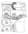
- Fig. 2 is a perspective view of a machine without tracks.
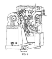
- Fig. 3 is a perspective view of a machine according to one embodiment.
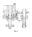
- Fig. 4 is a cross section of one embodiment of the primary and sorter starwheels illustrating the diverter mechanism and the vacuum manifold.
- Fig. 5 is a schematic block diagram illustrating one embodiment of the invention.
- sampling containers for quality assurance with the machine in the stopped condition does not accurately reflect containers processed at running speed conditions.
- the metal or other material bending/shaping may have subtle differences relative to containers running at production speed or at a significant reduction to production speed.
- the sample may not accurately reflect the container population.
- a linear deceleration from 200 RPM to stop in 10-seconds is the equivalent of approximately 17 revolutions, thus the last 17 process turrets are all at a reduced speed from the normal running line speed (in this example 200 RPM).
- a reduction of revolutions per minute to below fifty percent of production speed will not provide the material bending/shaping that would be obtained at production speed.
- the present invention in one embodiment retrieves containers from the machine at line speed in a sequential manner, without damaging the containers and while maintaining station integrity, thus ensuring the sample containers match the population processed.
- the machine would be operated at approximately production speed, e.g., at least ninety percent of production speed. In a further embodiment, the machine is operated at production speed.
- a container machine 10 comprises a processing turret 12 for processing containers.
- the processing turret may comprise a necker, flanger, reformer, reprofiler, inspection turret or other processing turret.
- the processing turret may or may not be included in the module containing the primary transfer starwheel that will be discussed next. Accordingly, the invention is not limited to modules containing a processing turret.
- a primary starwheel 14 is provided to receive containers from the processing turret 12.
- the primary starwheel 14 has ten pockets 16. Containers will be held in the pockets 16 and transferred along a normal pitch line transport path to an exit track 18.
- the machine of Fig. 1 further comprises a sorter starwheel 20 positioned adjacent to the primary starwheel 14 and driven in phase synchronization with the primary starwheel 14 for obtaining selected containers from the primary starwheel.
- the sorter starwheel 20 is shown having ten pockets 19, by way of example.
- the containers are held in the pockets 16 of the primary starwheel and pockets 19 of the sorter starwheel by vacuum provided through a manifold from a vacuum supply.
- containers that are ferromagnetic may be held in the pockets 16 and 19 by means of magnetization.
- the means for holding the containers in the pockets is not limiting on the invention.
- a sorter track 22 is provided as a path for containers held by the sorter vacuum starwheel.
- the design of the sorter starwheel may match the design features of the primary transfer starwheel.
- the sorter starwheel 20 may have the same pitch and number of pockets 19 as the primary starwheel 14. In this case with an equal pitch and number of pockets on the primary and sorter starwheels, a one-to-one drive mechanism will ensure the tangential velocity of the sorter starwheel to be substantially the same as the tangential velocity of the primary starwheel.
- the sorter starwheel may have a different number of pockets and/or have a different pitch diameter.
- a tangential velocity of the sorter starwheel in one embodiment is adjusted to be substantially the same as a tangential velocity of the primary starwheel.
- the drive for the sorter starwheel is not limiting on the invention, and may be implemented for example with timing belts, gearing, speed followers, or a secondary drive motor, etc.
- one or both of the primary starwheel and the sorter starwheel may be either quick-change or not quick-change.
- the quick-change feature would include a direct connection of the primary starwheel to a timing hub, so that starwheels with different sized pockets can be substituted to accommodate runs for containers with different height and diameter characteristics without timing adjustment. Additionally, adjustable tracks can be used to accommodate such different sized container runs.
- a diverter mechanism is provided to divert at least a selected one of the processed containers from its normal pitch line transport path on the primary starwheel to a pocket of the sorter starwheel at production speed and without damage to the container.
- the mechanism is designed to break a vacuum or magnetic hold on at least a selected one of the processed containers on the primary starwheel and eject the selected one of the processed containers to a pocket of the sorter starwheel.
- Fig. 4 is a cross section of the primary starwheel 14 and the sorter starwheel 20 with a vacuum manifold 40 and a vacuum port 42 to a pocket on the primary starwheel shown.
- a container 45 is held in the pocket for the primary starwheel 14 and the sorter starwheel 20 by means of a vacuum from the vacuum manifold.
- the diverter mechanism operates in one embodiment to break the vacuum from the primary starwheel 14 in a selected pocket 16, thereby allowing vacuum from the sorter starwheel to pull the container into the sorter starwheel pocket 19.
- Fig. 4 is a cross section of the primary starwheel 14 and the sorter starwheel 20 with a vacuum manifold 40 and a vacuum port 42 to a pocket on the primary starwheel shown.
- a container 45 is held in the pocket for the primary starwheel 14 and the sorter starwheel 20 by means of a vacuum from the vacuum manifold.
- the diverter mechanism operates in one embodiment to break the vacuum from the primary starwheel 14 in a selected pocket 16, thereby allowing vacuum from the sorter starwheel
- the mechanism to break the vacuum from the primary starwheel 14 comprises a compressed air jet (or nozzles) internal to the vacuum manifold 40 in the primary starwheel.
- this compressed air jet may be in communication with the primary starwheel.
- An air fitting 46 applies a compressed air jet from a compressed air source (not shown), by way of example, at 80 psi, to an opening 48 into the vacuum manifold with the jet angled toward the vacuum port 42.
- the air jet is activated by a fast response solenoid valve (not shown).
- the diverter mechanism may comprise a pair of blow-off nozzles on either side of the pocket of the primary starwheel to eject the container 45 into the sorter starwheel pocket 19 at the transfer point.
- the mechanism could comprise providing a significantly higher vacuum in the sorter starwheel pocket 19 relative to the vacuum holding the container in pocket 16 of the primary starwheel 14 to thereby break the vacuum hold and eject the container to pocket 19.
- a vacuum from a vacuum manifold that feeds both the primary and sorter starwheels may always be on/active and fed from the same vacuum source.
- a minimum design gap 26 between the pitch centerlines of the primary starwheel pocket and the sorter starwheel pocket may be necessary in some cases to ensure that the sorter starwheel vacuum does not overpower the normal transfer of containers during production (when the sorter is not engaged) and to further ensure that when containers are diverted, the transfer is made without damage to the container.
- the minimum design gap would be determined empirically in dependence on the machine design and the type and shape of the containers being processed, and could range from 0 to 2 millimeters, for example.
- the embodiment further comprises a timing device for causing the diverter mechanism to operate while the primary starwheel is rotating at production speed.
- a processor 50 is provided in one embodiment for generating timing signals to activate the diverter mechanism to generate the air jet or jets.
- a sorter container/product sequence may be programmed to obtain a single container from a discrete station, a series of containers from a discrete station (e.g. containers only from station #1), and a sequential series of containers from more than one station (e.g., a container sequence from stations 1,2,3,4).
- the sorter combinations are programmable for the timing of the break vacuum hold solenoid and a baseline pocket position determined by an encoder or resolver.
- a substantially vertical outer guide may be disposed in proximity to a dome end of the container and a substantially vertical outer guide may be disposed in proximity to an open end of the container at a transfer point between the primary starwheel and the sorter starwheel to inhibit movement along an axis of the containers.
- This is an optional feature that may be used to prevent container wobble during the transfer between the primary starwheel and the sorter starwheel pocket. Whether or not such a guide would be used would be dependent on such factors as the speed of the starwheels, and the container geometry (long narrow or short fat).
- an inspection turret e.g., light tester or vision system
- the reject containers so designated by the inspection turret may exit through the sorter starwheel 20, in substantially the same manner as a selected sorted container sequence obtained for quality control.
- Exit trackwork may have a "mouse-trap" design with a flapper plate ensuring that all rejected containers are routed through a track path that leads to scrapping.
- the "mouse-trap" flapper plate would be controlled by signals from the processor 50 connected to the inspection turret. It would operate to pass containers to the sorter track when electronically known to be in a QA sort routine.
- the timing device 50 may comprise logic for activating the diverter mechanism to transfer the rejected containers to the sorter starwheel 20.
- the air jets may be electrically timed at the same transfer point 24 to operate as a blow-off mechanism for the rejected containers. The rejected containers would then be directed to trackwork for scraping via the electronically controlled flapper plate.
- Controls such as light sensors or proximity sensors may be added to the system to ensure that a "design quantity of sorted containers" actually arrive through the sorter trackwork.
- An ink-printer system may be used to guarantee the proper sequenced containers (specific to station number) are retrieved.
- An ink-printer such as an ink jet may be utilized to deposit an identification marking on the containers (typically the dome end) indicating the station number the container came from and/or the fact that the container has been determined to be a reject.
- an ink printer 54 as shown in Fig. 5 may be included for depositing in synchronization with the timing device 50 an identification marking indicating a station number of origin.
- the ink printer may also be used for depositing in synchronization with the timing device an identification marking indicating a reject designation.
- the end user may collect the sorted containers manually or have them sent to an inspection location via automated conveyance mechanisms.
Landscapes
- Engineering & Computer Science (AREA)
- Mechanical Engineering (AREA)
- Specific Conveyance Elements (AREA)
Abstract
Description
- As a manufacturer of high-speed rotational equipment, Belvac's necking system machinery has the ability to process containers at speeds in excess of 3000 containers/minute (@ 250 RPM). It is required of the container maker to periodically "sample" finished containers from the machine for quality assurance (QA) purposes, to ensure product specifications are maintained, and containers such as cans or bottles are obtained without processing damage (dents, scuffing etc...). It is common for the container maker to stop the machine and remove a sequential series of containers equivalent to the number of processing stations per turret, or multiples thereof. The sequence relative to the station number is important: if quality assurance determines an adjustment is necessary, the specific station (or stations) where the adjustment is needed must be known. Because of the need to relate to a specific station, sample containers cannot be retrieved from conveyance downstream of the machine.
-
DE 29 13 702 A1 describes a container machine including a control piston for transferring a container between first and second starwheels. - According to the invention, a container machine is disclosed, comprising: an exit track for cans; a primary starwheel holding processed cans and moving the processed cans along a pitch line path toward the exit track; a sorter starwheel positioned adjacent to the primary starwheel and driven in phase synchronization with the primary starwheel; a sorter track for providing a path for cans held by the sorter starwheel; a can diverter mechanism to divert at least a selected one of the processed cans on the primary starwheel to a pocket of the sorter starwheel, the diverter mechanism including either a compressed air jet nozzle internal to a vacuum manifold, where the vacuum manifold communicates with each pocket of the primary starwheel, or a pair of blow-off nozzles, one on each side of the primary starwheel at a transfer area; and a timing device for causing the can diverter mechanism to operate while the primary starwheel is rotating at least at fifty percent of can production speed, or at least at ninety percent of the can production speed, or at least at can production speed.
- In a further embodiment, a minimum design gap to effect transfer of the cans without damage is provided between a pitch centerline of the primary starwheel and a pitch centerline of the sorter starwheel.
- In a yet further embodiment, at a transfer point between the primary starwheel and the sorter starwheel an outer guide is provided in proximity to a dome end of the can and an outer guide in proximity to an open end of the can, the outer guide disposed to inhibit movement along an axis of the can.
- In a yet further embodiment, the timing device is programmable to eject a sequence of cans from a same pocket of the primary starwheel.
- In a yet further embodiment, the timing device is programmable to eject a sequence of cans from a plurality of pocket of the primary starwheel.
- In a yet further embodiment, an ink printer is provided for depositing in synchronization with the timing device an identification marking indicating a station number of origin.
- In a yet further embodiment, a tangential velocity of the sorter starwheel is substantially the same as a tangential velocity of the primary starwheel. Preferably, the can production speed is approximately 3000 cans/minute.
- In a yet further embodiment, selected cans have been designated as rejects, and wherein the timing device further comprises logic for transferring the reject cans to the sorter starwheel.
- In a yet further embodiment, an ink printer is provided for depositing in synchronization with the timing device an identification marking indicating a reject designation.
- In a yet further embodiment, the diverter mechanism is programmed to operate at a production speed up to at least 250 revolutions per minute.
- In a yet further embodiment, the primary starwheel is a transfer starwheel.
- According to the invention, a method is disclosed for selecting and removing sample containers from a container machine, comprising: holding by a primary starwheel processed cans and moving the processed cans along a pitch line path to toward an exit track; removing selected cans, using either a compressed air jet nozzle internal to a vacuum manifold, where the vacuum manifold communicates with each pocket of the primary starwheel, or a pair of blow-off nozzles, one on each side of the primary starwheel at a transfer area, from the primary starwheel prior to the exit track while the primary starwheel is rotating at least at fifty percent of can production speed or at least at can production speed; and placing the selected cans after removal on to a sorter track.
- In a yet further embodiment, a step is provided of driving a sorter vacuum starwheel positioned adjacent to the primary starwheel in phase synchronization with the primary starwheel; and wherein the removing step removes the selected cans to the sorter vacuum starwheel.
- In a yet further embodiment, the removing step comprises breaking a vacuum hold on at least a selected one of the cans on the primary starwheel and ejecting the selected one of the cans.
- In a yet further embodiment, the breaking vacuum step comprises directing a jet of a gas at the selected container with a timing designed to remove the container at a predetermined position.
- In a yet further embodiment, the removing step comprises breaking a magnetic hold on at least a selected one of the cans on the primary starwheel and ejecting the selected one of the cans.
- In a yet further embodiment, the removing step comprises electronically programming to automatically eject a sequence of cans from a same pocket of the primary starwheel.
- In a yet further embodiment, the removing step comprises electronically programming to automatically eject a sequence of cans from a plurality of pocket of the primary starwheel.
- In a yet further embodiment, a step is provided of depositing on the selected cans an identification marking indicating a station number of origin.
- In a yet further embodiment, a step is provided of maintaining a tangential velocity of a sorter vacuum starwheel that is positioned adjacent to the primary starwheel for receiving the selected containers substantially the same as a tangential velocity of the primary starwheel.
- In a yet further embodiment, certain containers have been designated as rejects, and further comprising driving a sorter vacuum starwheel positioned adjacent to the primary starwheel in phase synchronization with the primary starwheel; and wherein the removing step removes both the selected containers to the sorter vacuum starwheel and the containers designated as rejects.
- In a yet further embodiment a vacuum is maintained on containers in individual pockets of the primary starwheel during the removing step.
-
Fig. 1 is a schematic diagram illustrating one embodiment of the invention. -
Fig. 2 is a perspective view of a machine without tracks. -
Fig. 3 is a perspective view of a machine according to one embodiment. -
Fig. 4 is a cross section of one embodiment of the primary and sorter starwheels illustrating the diverter mechanism and the vacuum manifold. -
Fig. 5 is a schematic block diagram illustrating one embodiment of the invention. - It has been discovered that sampling containers for quality assurance with the machine in the stopped condition does not accurately reflect containers processed at running speed conditions. During the time needed for the machine to decelerate from line speed to the stopped condition (typically a 10-second linear deceleration rate), the metal or other material bending/shaping may have subtle differences relative to containers running at production speed or at a significant reduction to production speed. Thus, the sample may not accurately reflect the container population. For example, a linear deceleration from 200 RPM to stop in 10-seconds is the equivalent of approximately 17 revolutions, thus the last 17 process turrets are all at a reduced speed from the normal running line speed (in this example 200 RPM). A reduction of revolutions per minute to below fifty percent of production speed will not provide the material bending/shaping that would be obtained at production speed.
- The present invention in one embodiment retrieves containers from the machine at line speed in a sequential manner, without damaging the containers and while maintaining station integrity, thus ensuring the sample containers match the population processed. In one embodiment, the machine would be operated at approximately production speed, e.g., at least ninety percent of production speed. In a further embodiment, the machine is operated at production speed.
- Referring now to
Figs. 1-3 , various embodiments of the invention are disclosed. Acontainer machine 10 is provided. Thecontainer machine 10 in one embodiment comprises aprocessing turret 12 for processing containers. By way of example, the processing turret may comprise a necker, flanger, reformer, reprofiler, inspection turret or other processing turret. Note however, that in modular machine designs, the processing turret may or may not be included in the module containing the primary transfer starwheel that will be discussed next. Accordingly, the invention is not limited to modules containing a processing turret. - A
primary starwheel 14 is provided to receive containers from theprocessing turret 12. In the example shown inFig. 1 , theprimary starwheel 14 has tenpockets 16. Containers will be held in thepockets 16 and transferred along a normal pitch line transport path to anexit track 18. - The machine of
Fig. 1 further comprises asorter starwheel 20 positioned adjacent to theprimary starwheel 14 and driven in phase synchronization with theprimary starwheel 14 for obtaining selected containers from the primary starwheel. Thesorter starwheel 20 is shown having tenpockets 19, by way of example. In one embodiment, the containers are held in thepockets 16 of the primary starwheel andpockets 19 of the sorter starwheel by vacuum provided through a manifold from a vacuum supply. In another embodiment, containers that are ferromagnetic may be held in thepockets sorter track 22 is provided as a path for containers held by the sorter vacuum starwheel. - In one embodiment, the design of the sorter starwheel may match the design features of the primary transfer starwheel. For example, the
sorter starwheel 20 may have the same pitch and number ofpockets 19 as theprimary starwheel 14. In this case with an equal pitch and number of pockets on the primary and sorter starwheels, a one-to-one drive mechanism will ensure the tangential velocity of the sorter starwheel to be substantially the same as the tangential velocity of the primary starwheel. Depending on space constraints, the sorter starwheel may have a different number of pockets and/or have a different pitch diameter. If the sorter starwheel has a different number of pockets and/or pitch diameter, then a tangential velocity of the sorter starwheel in one embodiment is adjusted to be substantially the same as a tangential velocity of the primary starwheel. The drive for the sorter starwheel is not limiting on the invention, and may be implemented for example with timing belts, gearing, speed followers, or a secondary drive motor, etc. Note that one or both of the primary starwheel and the sorter starwheel may be either quick-change or not quick-change. The quick-change feature would include a direct connection of the primary starwheel to a timing hub, so that starwheels with different sized pockets can be substituted to accommodate runs for containers with different height and diameter characteristics without timing adjustment. Additionally, adjustable tracks can be used to accommodate such different sized container runs. - A diverter mechanism is provided to divert at least a selected one of the processed containers from its normal pitch line transport path on the primary starwheel to a pocket of the sorter starwheel at production speed and without damage to the container. In one embodiment, the mechanism is designed to break a vacuum or magnetic hold on at least a selected one of the processed containers on the primary starwheel and eject the selected one of the processed containers to a pocket of the sorter starwheel.
- Referring to
Fig. 4 , an embodiment of the diverter mechanism is shown.Fig. 4 is a cross section of theprimary starwheel 14 and thesorter starwheel 20 with avacuum manifold 40 and avacuum port 42 to a pocket on the primary starwheel shown. Acontainer 45 is held in the pocket for theprimary starwheel 14 and thesorter starwheel 20 by means of a vacuum from the vacuum manifold. The diverter mechanism operates in one embodiment to break the vacuum from theprimary starwheel 14 in a selectedpocket 16, thereby allowing vacuum from the sorter starwheel to pull the container into thesorter starwheel pocket 19. In the embodiment ofFig. 4 , the mechanism to break the vacuum from theprimary starwheel 14 comprises a compressed air jet (or nozzles) internal to thevacuum manifold 40 in the primary starwheel. In one embodiment, this compressed air jet may be in communication with the primary starwheel. An air fitting 46 applies a compressed air jet from a compressed air source (not shown), by way of example, at 80 psi, to anopening 48 into the vacuum manifold with the jet angled toward thevacuum port 42. The air jet is activated by a fast response solenoid valve (not shown). - Alternatively, the diverter mechanism may comprise a pair of blow-off nozzles on either side of the pocket of the primary starwheel to eject the
container 45 into thesorter starwheel pocket 19 at the transfer point. Alternatively, the mechanism could comprise providing a significantly higher vacuum in thesorter starwheel pocket 19 relative to the vacuum holding the container inpocket 16 of theprimary starwheel 14 to thereby break the vacuum hold and eject the container topocket 19. - Note that in embodiments using the air jets, a vacuum from a vacuum manifold that feeds both the primary and sorter starwheels may always be on/active and fed from the same vacuum source. With this embodiment, there is no need for a high response vacuum supply solenoid supply to quickly turn on for a given
pocket 19 to overpower the vacuum hold inpocket 16, nor is there a need for a high speed evacuation system to quickly remove or reduce to regular vacuum on the nextpocket following pocket 19 which is not to be diverted. - Note that a
minimum design gap 26 between the pitch centerlines of the primary starwheel pocket and the sorter starwheel pocket may be necessary in some cases to ensure that the sorter starwheel vacuum does not overpower the normal transfer of containers during production (when the sorter is not engaged) and to further ensure that when containers are diverted, the transfer is made without damage to the container. The minimum design gap would be determined empirically in dependence on the machine design and the type and shape of the containers being processed, and could range from 0 to 2 millimeters, for example. - The embodiment further comprises a timing device for causing the diverter mechanism to operate while the primary starwheel is rotating at production speed. Although not limiting on the invention, some machines have production speeds on the order of 180-250 revolutions per minute. Referring to
Fig. 5 , a processor 50 is provided in one embodiment for generating timing signals to activate the diverter mechanism to generate the air jet or jets. For example, a sorter container/product sequence may be programmed to obtain a single container from a discrete station, a series of containers from a discrete station (e.g. containers only from station #1), and a sequential series of containers from more than one station (e.g., a container sequence from stations 1,2,3,4...). The sorter combinations are programmable for the timing of the break vacuum hold solenoid and a baseline pocket position determined by an encoder or resolver. - In one embodiment, a substantially vertical outer guide may be disposed in proximity to a dome end of the container and a substantially vertical outer guide may be disposed in proximity to an open end of the container at a transfer point between the primary starwheel and the sorter starwheel to inhibit movement along an axis of the containers. This is an optional feature that may be used to prevent container wobble during the transfer between the primary starwheel and the sorter starwheel pocket. Whether or not such a guide would be used would be dependent on such factors as the speed of the starwheels, and the container geometry (long narrow or short fat).
- In a case where an inspection turret (e.g., light tester or vision system) is the
adjacent process turret 12 to theprimary starwheel 14, the reject containers so designated by the inspection turret may exit through thesorter starwheel 20, in substantially the same manner as a selected sorted container sequence obtained for quality control. Exit trackwork may have a "mouse-trap" design with a flapper plate ensuring that all rejected containers are routed through a track path that leads to scrapping. The "mouse-trap" flapper plate would be controlled by signals from the processor 50 connected to the inspection turret. It would operate to pass containers to the sorter track when electronically known to be in a QA sort routine. Feedback from inspection electronics will determine if a "reject" container is part of a sampling/sorting sequence and will include appropriate operator communications as to the validity of containers in a sequence. Thus in one embodiment, where selected containers have been designated as rejects in an inspection station, the timing device 50 may comprise logic for activating the diverter mechanism to transfer the rejected containers to thesorter starwheel 20. For example, the air jets may be electrically timed at thesame transfer point 24 to operate as a blow-off mechanism for the rejected containers. The rejected containers would then be directed to trackwork for scraping via the electronically controlled flapper plate. - There are many ways to ensure a proper quantity of containers, as well as the validity of containers are obtained from a sampling event. Controls such as light sensors or proximity sensors may be added to the system to ensure that a "design quantity of sorted containers" actually arrive through the sorter trackwork. An ink-printer system may be used to guarantee the proper sequenced containers (specific to station number) are retrieved.
- An ink-printer such as an ink jet may be utilized to deposit an identification marking on the containers (typically the dome end) indicating the station number the container came from and/or the fact that the container has been determined to be a reject. Thus, an
ink printer 54 as shown inFig. 5 may be included for depositing in synchronization with the timing device 50 an identification marking indicating a station number of origin. The ink printer may also be used for depositing in synchronization with the timing device an identification marking indicating a reject designation. - The end user may collect the sorted containers manually or have them sent to an inspection location via automated conveyance mechanisms.
- It should be noted that although the description provided herein show a specific order of method steps, it is understood that the order of these steps may differ from what is depicted. Also two or more steps may be performed concurrently or with partial concurrence. Such variation will depend on the software and hardware systems chosen, and more generally, on designer choice. It is understood that all such variations are within the scope of the invention without departing from the scope of the appended claims. It should also be noted that the word "component" as used herein and in the claims is intended to encompass implementations using one or more lines of software code, and/or hardware implementations, and/or equipment for receiving manual inputs.
- The foregoing description of a preferred embodiments of the invention has been presented for purposes of illustration and description. It is not intended to be exhaustive nor to limit the invention to the precise form disclosed, and modifications and variations are possible in light of the above teachings or may be acquired from practice of the invention without departing from the scope of the appended claims. The embodiments were chosen and described in order to explain the principals of the invention and its practical application to enable one skilled in the art to utilize the invention in various embodiments and with various modifications as are suited to the particular use contemplated. It is intended that the scope of the invention be defined by the claims appended hereto.
Claims (15)
- A container machine (10), characterised by comprising:an exit track (18) for cans;a primary starwheel (14) holding processed cans and moving the processed cans along a pitch line path toward the exit track;a sorter starwheel (20) positioned adjacent to the primary starwheel and driven in phase synchronization with the primary starwheel;a sorter track (22) for providing a path for cans held by the sorter starwheel;a can diverter mechanism to divert at least a selected one of the processed cans on the primary starwheel to a pocket of the sorter starwheel, the can diverter mechanism including either a compressed air jet nozzle internal to a vacuum manifold (40), where the vacuum manifold communicates with each pocket (16) of the primary starwheel, or a pair of blow-off nozzles, one on each side of the primary starwheel at a transfer area; anda timing device (50) for causing the can diverter mechanism to operate while the primary starwheel is rotating at least at fifty percent of can production speed, or at least at ninety percent of the can production speed, or at least at can production speed.
- The machine as defined in claim 1, wherein a minimum design gap (26) to effect transfer of the cans without damage is provided between a pitch centerline of the primary starwheel and a pitch centerline of the sorter starwheel.
- The machine as defined in claim 1, further comprising at a transfer point (24) between the primary starwheel and the sorter starwheel an outer guide in proximity to a dome end of the can and an outer guide in proximity to an open end of the can, the outer guide disposed to inhibit movement along an axis of the can.
- The machine as defined in claim 1, further comprising
an ink printer (54) for depositing in synchronization with the timing device an identification marking indicating a reject designation or a station number of origin. - The machine as defined in claim 1, wherein a tangential velocity of the sorter starwheel is substantially the same as a tangential velocity of the primary starwheel, and
wherein the production speed is approximately 3000 cans/minute. - The machine as defined in claim 1, wherein selected cans have been designated as rejects, and wherein the timing device further comprises logic for transferring the reject cans to the sorter starwheel.
- A method for selecting and removing sample containers from a container machine (10), characterised by comprising the steps of:holding by a primary starwheel (14) processed cans and moving the processed cans along a pitch line path to toward an exit track (18);removing selected cans using either a compressesd air jet nozzle internal to a vacuum manifold (40), where the vacuum manifold communicates with each pocket (16) of the primary starwheel, or a pair of blow-off nozzles, one on each side of the primary starwheel at a transfer area, from the primary starwheel prior to the exit track while the primary starwheel is rotating at least at fifty percent of can production speed or at least at can production speed; andplacing the selected cans after removal on to a sorter track (22).
- The method as defined in claim 7, further comprising:driving a sorter vacuum starwheel (20) positioned adjacent to the primary starwheel in phase synchronization with the primary starwheel; andwherein the removing step removes the selected cans to the sorter vacuum starwheel.
- The method as defined in claim 7, wherein the removing step comprises at least one of breaking a vacuum hold on at least a selected one of the cans on the primary starwheel and ejecting the selected one of the cans or breaking a magnetic hold on at least a selected one of the cans on the primary starwheel and ejecting the selected one of the cans.
- The method as defined in claim 9, wherein the breaking vacuum step comprises directing a jet of a gas at the selected can with a timing designed to remove the can at a predetermined position and the breaking a magnetic hold step comprises directing a jet of a gas at the selected can with a timing designed to remove the can at a predetermined position.
- The method as defined in claim 7, wherein the removing step comprises electronically programming to automatically eject a sequence of cans from a same pocket or a plurality of pockets of the primary starwheel.
- The method as defined in claim 7, further comprising
depositing on the selected cans an identification marking indicating a station number of origin. - The method as defined in claim 7, further comprising:maintaining a tangential velocity of a sorter vacuum starwheel that is positioned adjacent to the primary starwheel for receiving the selected cans substantially the same as a tangential velocity of the primary starwheel.
- The method as defined in claim 7, wherein certain cans have been designated as rejects, and further comprising
driving a sorter vacuum starwheel positioned adjacent to the primary starwheel in phase synchronization with the primary starwheel; and
wherein the removing step removes both the selected cans to the sorter vacuum starwheel and the cans designated as rejects. - The method as defined in claim 7, further comprising maintaining a vacuum on cans in individual pockets of the primary starwheel during the removing step and wherein the production speed is approximately 3000 cans/minute.
Applications Claiming Priority (2)
| Application Number | Priority Date | Filing Date | Title |
|---|---|---|---|
| US11/859,318 US7568573B2 (en) | 2007-09-21 | 2007-09-21 | High speed selective container sorter |
| PCT/US2008/010837 WO2009042055A1 (en) | 2007-09-21 | 2008-09-18 | High speed selective container sorter |
Publications (2)
| Publication Number | Publication Date |
|---|---|
| EP2205510A1 EP2205510A1 (en) | 2010-07-14 |
| EP2205510B1 true EP2205510B1 (en) | 2012-06-13 |
Family
ID=40210847
Family Applications (1)
| Application Number | Title | Priority Date | Filing Date |
|---|---|---|---|
| EP08832913A Active EP2205510B1 (en) | 2007-09-21 | 2008-09-18 | High speed selective can sorter |
Country Status (3)
| Country | Link |
|---|---|
| US (1) | US7568573B2 (en) |
| EP (1) | EP2205510B1 (en) |
| WO (1) | WO2009042055A1 (en) |
Cited By (1)
| Publication number | Priority date | Publication date | Assignee | Title |
|---|---|---|---|---|
| EP3790683B1 (en) * | 2018-05-11 | 2025-03-05 | Stolle Machinery Company, LLC | Drive assembly |
Families Citing this family (9)
| Publication number | Priority date | Publication date | Assignee | Title |
|---|---|---|---|---|
| ITBO20050779A1 (en) * | 2005-12-22 | 2006-03-23 | Gd Spa | CONVEYING UNIT OF SMOKE ITEMS |
| US8601843B2 (en) | 2008-04-24 | 2013-12-10 | Crown Packaging Technology, Inc. | High speed necking configuration |
| US8297098B2 (en) * | 2009-02-26 | 2012-10-30 | Belvac Production Machinery, Inc. | Dual ram assembly for necker machine |
| WO2015076823A1 (en) | 2013-11-22 | 2015-05-28 | Silgan Containers Llc | Can-making apparatus with trimmer chute |
| PL3110576T3 (en) | 2014-02-27 | 2022-08-16 | Belvac Production Machinery, Inc. | Recirculation systems and methods for can and bottle making machinery |
| JP6716858B2 (en) * | 2015-01-15 | 2020-07-01 | 東洋製罐株式会社 | Filling and winding device and filling and winding method for can body |
| CN112105571B (en) * | 2018-05-11 | 2022-04-19 | 斯多里机械有限责任公司 | Quick change feature for a feed-in assembly |
| DE102019106075A1 (en) * | 2019-03-11 | 2020-09-17 | Khs Gmbh | Transport device and method for transporting containers around a vertical machine axis |
| CN113573994B (en) * | 2019-03-14 | 2023-10-27 | 费森尤斯卡比奥地利有限公司 | Facility and method for sorting containers |
Family Cites Families (12)
| Publication number | Priority date | Publication date | Assignee | Title |
|---|---|---|---|---|
| DE1084640B (en) | 1956-10-05 | 1960-06-30 | Crown Cork & Seal Co | Device for dividing containers delivered on a first conveyor onto two further conveyors |
| US2985008A (en) * | 1957-05-31 | 1961-05-23 | Nat Can Corp | Transfer mechanism |
| US3687285A (en) * | 1970-12-23 | 1972-08-29 | Clifford H Messervey | Positive two channel can discharge |
| GB1591158A (en) * | 1976-11-09 | 1981-06-17 | Cleamax Ltd | High speed can handling mechanism |
| DE2704614C2 (en) | 1977-02-04 | 1982-09-30 | Alcoa Deutschland Gmbh Maschinenbau, 6806 Viernheim | Device for distributing upright containers, in particular bottles |
| DE2913702C2 (en) | 1979-04-05 | 1982-08-12 | Alcoa Deutschland Gmbh Maschinenbau, 6806 Viernheim | Transport switch for upright containers, especially bottles |
| IT1150533B (en) * | 1981-04-25 | 1986-12-10 | Hauni Werke Koerber & Co Kg | TRANSPORT DEVICE, FOR TOBACCO WORKING INDUSTRY ITEMS |
| DE3141364C2 (en) * | 1981-10-17 | 1984-12-20 | Krones Ag Hermann Kronseder Maschinenfabrik, 8402 Neutraubling | Device for distributing upright vessels |
| FR2519887A1 (en) * | 1982-01-15 | 1983-07-22 | Saint Gobain Emballage | SORTING DEVICE ON A HORIZONTAL CONVEYOR |
| IT1245985B (en) | 1991-02-01 | 1994-11-07 | Gd Spa | DISTRIBUTOR DEVICE FOR THE FEEDING OF PRODUCTS APPLIED TO A USING MACHINE. |
| US5231926A (en) * | 1991-10-11 | 1993-08-03 | Sequa Corporation | Apparatus and method for substantially reducing can spacing and speed to match chain pins |
| US6523670B1 (en) * | 2001-05-17 | 2003-02-25 | Goldco Industries, Inc. | Article conveyance having line and/or spacing adjustment |
-
2007
- 2007-09-21 US US11/859,318 patent/US7568573B2/en active Active
-
2008
- 2008-09-18 EP EP08832913A patent/EP2205510B1/en active Active
- 2008-09-18 WO PCT/US2008/010837 patent/WO2009042055A1/en not_active Ceased
Cited By (1)
| Publication number | Priority date | Publication date | Assignee | Title |
|---|---|---|---|---|
| EP3790683B1 (en) * | 2018-05-11 | 2025-03-05 | Stolle Machinery Company, LLC | Drive assembly |
Also Published As
| Publication number | Publication date |
|---|---|
| US20090078716A1 (en) | 2009-03-26 |
| WO2009042055A1 (en) | 2009-04-02 |
| EP2205510A1 (en) | 2010-07-14 |
| US7568573B2 (en) | 2009-08-04 |
Similar Documents
| Publication | Publication Date | Title |
|---|---|---|
| US7568573B2 (en) | High speed selective container sorter | |
| EP2251114B1 (en) | Method and apparatus for trimming a can | |
| CN107599357B (en) | Inspection and ejector unit | |
| US10589453B2 (en) | Device and method for transporting preforms in the region of a blow-molding machine | |
| DE102014012528A1 (en) | Device and method for transporting preforms in the area of a blow molding machine | |
| US5383322A (en) | Single pack reject mechanism for cigarette packaging machine and method | |
| EP3246258B1 (en) | Can filling/seaming device and can filling/seaming method | |
| US3710937A (en) | Method and apparatus for transporting glassware | |
| JP6843729B2 (en) | Can manufacturing equipment | |
| EP0957028B1 (en) | Method for packaging articles into containers | |
| CN101553354A (en) | Method and apparatus for producing plastic packaging containers | |
| EP2382146B2 (en) | A conveyor for containers, such as bottles, to be processed and for processed containers for operating machines of the type with a rotary carrousel | |
| US5784855A (en) | Apparatus for the production of, in particular, cigarette packs | |
| US11155454B2 (en) | Container processing system | |
| US9579693B2 (en) | Method and system for arranging a plurality of articles moved in a mass flow | |
| US6401904B1 (en) | Method and apparatus for separating objects | |
| US11795010B2 (en) | Transport device and method for transporting containers in a manner revolving about a vertical machine axis | |
| US6536294B1 (en) | Inspection machine | |
| CN108369759B (en) | Testing device for testing coin blanks | |
| EP1695926B1 (en) | Work unit for conveying bottles between two stations and for rejecting faulty bottles | |
| JP2023044460A (en) | Container processing system | |
| JP7582398B1 (en) | Bottomed cylindrical body processing device | |
| US5669482A (en) | Trailing end air hold-up assembly | |
| CN105034571B (en) | Machine for printing hollow objects | |
| KR100392979B1 (en) | air-chute part for steel-can opener's auto arraying and feeding apparatus |
Legal Events
| Date | Code | Title | Description |
|---|---|---|---|
| PUAI | Public reference made under article 153(3) epc to a published international application that has entered the european phase |
Free format text: ORIGINAL CODE: 0009012 |
|
| 17P | Request for examination filed |
Effective date: 20100406 |
|
| AK | Designated contracting states |
Kind code of ref document: A1 Designated state(s): AT BE BG CH CY CZ DE DK EE ES FI FR GB GR HR HU IE IS IT LI LT LU LV MC MT NL NO PL PT RO SE SI SK TR |
|
| AX | Request for extension of the european patent |
Extension state: AL BA MK RS |
|
| DAX | Request for extension of the european patent (deleted) | ||
| 17Q | First examination report despatched |
Effective date: 20110210 |
|
| RTI1 | Title (correction) |
Free format text: HIGH SPEED SELECTIVE CAN SORTER |
|
| GRAP | Despatch of communication of intention to grant a patent |
Free format text: ORIGINAL CODE: EPIDOSNIGR1 |
|
| GRAS | Grant fee paid |
Free format text: ORIGINAL CODE: EPIDOSNIGR3 |
|
| GRAA | (expected) grant |
Free format text: ORIGINAL CODE: 0009210 |
|
| AK | Designated contracting states |
Kind code of ref document: B1 Designated state(s): AT BE BG CH CY CZ DE DK EE ES FI FR GB GR HR HU IE IS IT LI LT LU LV MC MT NL NO PL PT RO SE SI SK TR |
|
| REG | Reference to a national code |
Ref country code: GB Ref legal event code: FG4D |
|
| REG | Reference to a national code |
Ref country code: AT Ref legal event code: REF Ref document number: 561880 Country of ref document: AT Kind code of ref document: T Effective date: 20120615 Ref country code: CH Ref legal event code: EP |
|
| REG | Reference to a national code |
Ref country code: IE Ref legal event code: FG4D |
|
| REG | Reference to a national code |
Ref country code: DE Ref legal event code: R096 Ref document number: 602008016323 Country of ref document: DE Effective date: 20120816 |
|
| REG | Reference to a national code |
Ref country code: NL Ref legal event code: VDEP Effective date: 20120613 |
|
| PG25 | Lapsed in a contracting state [announced via postgrant information from national office to epo] |
Ref country code: CY Free format text: LAPSE BECAUSE OF FAILURE TO SUBMIT A TRANSLATION OF THE DESCRIPTION OR TO PAY THE FEE WITHIN THE PRESCRIBED TIME-LIMIT Effective date: 20120613 Ref country code: NO Free format text: LAPSE BECAUSE OF FAILURE TO SUBMIT A TRANSLATION OF THE DESCRIPTION OR TO PAY THE FEE WITHIN THE PRESCRIBED TIME-LIMIT Effective date: 20120913 Ref country code: FI Free format text: LAPSE BECAUSE OF FAILURE TO SUBMIT A TRANSLATION OF THE DESCRIPTION OR TO PAY THE FEE WITHIN THE PRESCRIBED TIME-LIMIT Effective date: 20120613 Ref country code: SE Free format text: LAPSE BECAUSE OF FAILURE TO SUBMIT A TRANSLATION OF THE DESCRIPTION OR TO PAY THE FEE WITHIN THE PRESCRIBED TIME-LIMIT Effective date: 20120613 Ref country code: LT Free format text: LAPSE BECAUSE OF FAILURE TO SUBMIT A TRANSLATION OF THE DESCRIPTION OR TO PAY THE FEE WITHIN THE PRESCRIBED TIME-LIMIT Effective date: 20120613 |
|
| REG | Reference to a national code |
Ref country code: AT Ref legal event code: MK05 Ref document number: 561880 Country of ref document: AT Kind code of ref document: T Effective date: 20120613 |
|
| REG | Reference to a national code |
Ref country code: LT Ref legal event code: MG4D Effective date: 20120613 |
|
| PG25 | Lapsed in a contracting state [announced via postgrant information from national office to epo] |
Ref country code: GR Free format text: LAPSE BECAUSE OF FAILURE TO SUBMIT A TRANSLATION OF THE DESCRIPTION OR TO PAY THE FEE WITHIN THE PRESCRIBED TIME-LIMIT Effective date: 20120914 Ref country code: LV Free format text: LAPSE BECAUSE OF FAILURE TO SUBMIT A TRANSLATION OF THE DESCRIPTION OR TO PAY THE FEE WITHIN THE PRESCRIBED TIME-LIMIT Effective date: 20120613 Ref country code: SI Free format text: LAPSE BECAUSE OF FAILURE TO SUBMIT A TRANSLATION OF THE DESCRIPTION OR TO PAY THE FEE WITHIN THE PRESCRIBED TIME-LIMIT Effective date: 20120613 Ref country code: HR Free format text: LAPSE BECAUSE OF FAILURE TO SUBMIT A TRANSLATION OF THE DESCRIPTION OR TO PAY THE FEE WITHIN THE PRESCRIBED TIME-LIMIT Effective date: 20120613 |
|
| PG25 | Lapsed in a contracting state [announced via postgrant information from national office to epo] |
Ref country code: SK Free format text: LAPSE BECAUSE OF FAILURE TO SUBMIT A TRANSLATION OF THE DESCRIPTION OR TO PAY THE FEE WITHIN THE PRESCRIBED TIME-LIMIT Effective date: 20120613 Ref country code: EE Free format text: LAPSE BECAUSE OF FAILURE TO SUBMIT A TRANSLATION OF THE DESCRIPTION OR TO PAY THE FEE WITHIN THE PRESCRIBED TIME-LIMIT Effective date: 20120613 Ref country code: RO Free format text: LAPSE BECAUSE OF FAILURE TO SUBMIT A TRANSLATION OF THE DESCRIPTION OR TO PAY THE FEE WITHIN THE PRESCRIBED TIME-LIMIT Effective date: 20120613 Ref country code: CZ Free format text: LAPSE BECAUSE OF FAILURE TO SUBMIT A TRANSLATION OF THE DESCRIPTION OR TO PAY THE FEE WITHIN THE PRESCRIBED TIME-LIMIT Effective date: 20120613 Ref country code: BE Free format text: LAPSE BECAUSE OF FAILURE TO SUBMIT A TRANSLATION OF THE DESCRIPTION OR TO PAY THE FEE WITHIN THE PRESCRIBED TIME-LIMIT Effective date: 20120613 Ref country code: AT Free format text: LAPSE BECAUSE OF FAILURE TO SUBMIT A TRANSLATION OF THE DESCRIPTION OR TO PAY THE FEE WITHIN THE PRESCRIBED TIME-LIMIT Effective date: 20120613 Ref country code: IS Free format text: LAPSE BECAUSE OF FAILURE TO SUBMIT A TRANSLATION OF THE DESCRIPTION OR TO PAY THE FEE WITHIN THE PRESCRIBED TIME-LIMIT Effective date: 20121013 |
|
| PG25 | Lapsed in a contracting state [announced via postgrant information from national office to epo] |
Ref country code: PL Free format text: LAPSE BECAUSE OF FAILURE TO SUBMIT A TRANSLATION OF THE DESCRIPTION OR TO PAY THE FEE WITHIN THE PRESCRIBED TIME-LIMIT Effective date: 20120613 Ref country code: PT Free format text: LAPSE BECAUSE OF FAILURE TO SUBMIT A TRANSLATION OF THE DESCRIPTION OR TO PAY THE FEE WITHIN THE PRESCRIBED TIME-LIMIT Effective date: 20121015 Ref country code: IT Free format text: LAPSE BECAUSE OF FAILURE TO SUBMIT A TRANSLATION OF THE DESCRIPTION OR TO PAY THE FEE WITHIN THE PRESCRIBED TIME-LIMIT Effective date: 20120613 |
|
| PG25 | Lapsed in a contracting state [announced via postgrant information from national office to epo] |
Ref country code: NL Free format text: LAPSE BECAUSE OF FAILURE TO SUBMIT A TRANSLATION OF THE DESCRIPTION OR TO PAY THE FEE WITHIN THE PRESCRIBED TIME-LIMIT Effective date: 20120613 |
|
| PLBE | No opposition filed within time limit |
Free format text: ORIGINAL CODE: 0009261 |
|
| STAA | Information on the status of an ep patent application or granted ep patent |
Free format text: STATUS: NO OPPOSITION FILED WITHIN TIME LIMIT |
|
| PG25 | Lapsed in a contracting state [announced via postgrant information from national office to epo] |
Ref country code: MC Free format text: LAPSE BECAUSE OF NON-PAYMENT OF DUE FEES Effective date: 20120930 Ref country code: ES Free format text: LAPSE BECAUSE OF FAILURE TO SUBMIT A TRANSLATION OF THE DESCRIPTION OR TO PAY THE FEE WITHIN THE PRESCRIBED TIME-LIMIT Effective date: 20120924 Ref country code: DK Free format text: LAPSE BECAUSE OF FAILURE TO SUBMIT A TRANSLATION OF THE DESCRIPTION OR TO PAY THE FEE WITHIN THE PRESCRIBED TIME-LIMIT Effective date: 20120613 |
|
| REG | Reference to a national code |
Ref country code: CH Ref legal event code: PL |
|
| 26N | No opposition filed |
Effective date: 20130314 |
|
| REG | Reference to a national code |
Ref country code: IE Ref legal event code: MM4A |
|
| REG | Reference to a national code |
Ref country code: DE Ref legal event code: R097 Ref document number: 602008016323 Country of ref document: DE Effective date: 20130314 |
|
| PG25 | Lapsed in a contracting state [announced via postgrant information from national office to epo] |
Ref country code: BG Free format text: LAPSE BECAUSE OF FAILURE TO SUBMIT A TRANSLATION OF THE DESCRIPTION OR TO PAY THE FEE WITHIN THE PRESCRIBED TIME-LIMIT Effective date: 20120913 Ref country code: CH Free format text: LAPSE BECAUSE OF NON-PAYMENT OF DUE FEES Effective date: 20120930 Ref country code: LI Free format text: LAPSE BECAUSE OF NON-PAYMENT OF DUE FEES Effective date: 20120930 Ref country code: IE Free format text: LAPSE BECAUSE OF NON-PAYMENT OF DUE FEES Effective date: 20120918 |
|
| PG25 | Lapsed in a contracting state [announced via postgrant information from national office to epo] |
Ref country code: MT Free format text: LAPSE BECAUSE OF FAILURE TO SUBMIT A TRANSLATION OF THE DESCRIPTION OR TO PAY THE FEE WITHIN THE PRESCRIBED TIME-LIMIT Effective date: 20120613 |
|
| PG25 | Lapsed in a contracting state [announced via postgrant information from national office to epo] |
Ref country code: TR Free format text: LAPSE BECAUSE OF FAILURE TO SUBMIT A TRANSLATION OF THE DESCRIPTION OR TO PAY THE FEE WITHIN THE PRESCRIBED TIME-LIMIT Effective date: 20120613 |
|
| PG25 | Lapsed in a contracting state [announced via postgrant information from national office to epo] |
Ref country code: LU Free format text: LAPSE BECAUSE OF NON-PAYMENT OF DUE FEES Effective date: 20120918 |
|
| PG25 | Lapsed in a contracting state [announced via postgrant information from national office to epo] |
Ref country code: HU Free format text: LAPSE BECAUSE OF FAILURE TO SUBMIT A TRANSLATION OF THE DESCRIPTION OR TO PAY THE FEE WITHIN THE PRESCRIBED TIME-LIMIT Effective date: 20080918 |
|
| REG | Reference to a national code |
Ref country code: FR Ref legal event code: PLFP Year of fee payment: 8 |
|
| PG25 | Lapsed in a contracting state [announced via postgrant information from national office to epo] |
Ref country code: IT Free format text: LAPSE BECAUSE OF FAILURE TO SUBMIT A TRANSLATION OF THE DESCRIPTION OR TO PAY THE FEE WITHIN THE PRESCRIBED TIME-LIMIT Effective date: 20120918 |
|
| REG | Reference to a national code |
Ref country code: FR Ref legal event code: PLFP Year of fee payment: 9 |
|
| PGRI | Patent reinstated in contracting state [announced from national office to epo] |
Ref country code: IT Effective date: 20170104 |
|
| REG | Reference to a national code |
Ref country code: FR Ref legal event code: PLFP Year of fee payment: 10 |
|
| REG | Reference to a national code |
Ref country code: FR Ref legal event code: PLFP Year of fee payment: 11 |
|
| P01 | Opt-out of the competence of the unified patent court (upc) registered |
Effective date: 20230524 |
|
| PGFP | Annual fee paid to national office [announced via postgrant information from national office to epo] |
Ref country code: DE Payment date: 20250919 Year of fee payment: 18 |
|
| PGFP | Annual fee paid to national office [announced via postgrant information from national office to epo] |
Ref country code: IT Payment date: 20250923 Year of fee payment: 18 |
|
| PGFP | Annual fee paid to national office [announced via postgrant information from national office to epo] |
Ref country code: GB Payment date: 20250918 Year of fee payment: 18 |
|
| PGFP | Annual fee paid to national office [announced via postgrant information from national office to epo] |
Ref country code: FR Payment date: 20250919 Year of fee payment: 18 |