EP2205042A1 - System, method and apparatus for pulsed induction heat removal of components from structural assemblies - Google Patents
System, method and apparatus for pulsed induction heat removal of components from structural assemblies Download PDFInfo
- Publication number
- EP2205042A1 EP2205042A1 EP09180743A EP09180743A EP2205042A1 EP 2205042 A1 EP2205042 A1 EP 2205042A1 EP 09180743 A EP09180743 A EP 09180743A EP 09180743 A EP09180743 A EP 09180743A EP 2205042 A1 EP2205042 A1 EP 2205042A1
- Authority
- EP
- European Patent Office
- Prior art keywords
- substrate
- tool
- adhesive
- component
- extender
- Prior art date
- Legal status (The legal status is an assumption and is not a legal conclusion. Google has not performed a legal analysis and makes no representation as to the accuracy of the status listed.)
- Granted
Links
- 230000006698 induction Effects 0.000 title claims abstract description 18
- 238000000034 method Methods 0.000 title claims description 30
- 230000000712 assembly Effects 0.000 title description 6
- 238000000429 assembly Methods 0.000 title description 6
- 239000000758 substrate Substances 0.000 claims abstract description 55
- 239000000853 adhesive Substances 0.000 claims abstract description 43
- 230000001070 adhesive effect Effects 0.000 claims abstract description 43
- 238000010438 heat treatment Methods 0.000 claims abstract description 20
- 239000004606 Fillers/Extenders Substances 0.000 claims description 23
- 239000000463 material Substances 0.000 claims description 10
- 239000000523 sample Substances 0.000 claims description 10
- 238000007790 scraping Methods 0.000 claims description 5
- 230000000295 complement effect Effects 0.000 claims description 4
- 230000000881 depressing effect Effects 0.000 claims description 4
- 238000001816 cooling Methods 0.000 claims description 3
- 239000000306 component Substances 0.000 claims description 2
- 238000013021 overheating Methods 0.000 abstract description 4
- 239000002131 composite material Substances 0.000 description 20
- 230000008901 benefit Effects 0.000 description 5
- 238000010420 art technique Methods 0.000 description 3
- 239000002184 metal Substances 0.000 description 3
- 229910052751 metal Inorganic materials 0.000 description 3
- XEEYBQQBJWHFJM-UHFFFAOYSA-N Iron Chemical compound [Fe] XEEYBQQBJWHFJM-UHFFFAOYSA-N 0.000 description 2
- 238000009529 body temperature measurement Methods 0.000 description 2
- 238000009434 installation Methods 0.000 description 2
- 230000000873 masking effect Effects 0.000 description 2
- 229920001296 polysiloxane Polymers 0.000 description 2
- 238000003825 pressing Methods 0.000 description 2
- 229910000831 Steel Inorganic materials 0.000 description 1
- 230000032798 delamination Effects 0.000 description 1
- 238000010586 diagram Methods 0.000 description 1
- 229910052742 iron Inorganic materials 0.000 description 1
- 238000004519 manufacturing process Methods 0.000 description 1
- 238000000926 separation method Methods 0.000 description 1
- 239000010959 steel Substances 0.000 description 1
Images




Classifications
-
- H—ELECTRICITY
- H05—ELECTRIC TECHNIQUES NOT OTHERWISE PROVIDED FOR
- H05B—ELECTRIC HEATING; ELECTRIC LIGHT SOURCES NOT OTHERWISE PROVIDED FOR; CIRCUIT ARRANGEMENTS FOR ELECTRIC LIGHT SOURCES, IN GENERAL
- H05B3/00—Ohmic-resistance heating
- H05B3/40—Heating elements having the shape of rods or tubes
- H05B3/42—Heating elements having the shape of rods or tubes non-flexible
-
- H—ELECTRICITY
- H05—ELECTRIC TECHNIQUES NOT OTHERWISE PROVIDED FOR
- H05B—ELECTRIC HEATING; ELECTRIC LIGHT SOURCES NOT OTHERWISE PROVIDED FOR; CIRCUIT ARRANGEMENTS FOR ELECTRIC LIGHT SOURCES, IN GENERAL
- H05B6/00—Heating by electric, magnetic or electromagnetic fields
- H05B6/02—Induction heating
- H05B6/06—Control, e.g. of temperature, of power
-
- H—ELECTRICITY
- H05—ELECTRIC TECHNIQUES NOT OTHERWISE PROVIDED FOR
- H05B—ELECTRIC HEATING; ELECTRIC LIGHT SOURCES NOT OTHERWISE PROVIDED FOR; CIRCUIT ARRANGEMENTS FOR ELECTRIC LIGHT SOURCES, IN GENERAL
- H05B6/00—Heating by electric, magnetic or electromagnetic fields
- H05B6/02—Induction heating
- H05B6/10—Induction heating apparatus, other than furnaces, for specific applications
- H05B6/14—Tools, e.g. nozzles, rollers, calenders
-
- H—ELECTRICITY
- H05—ELECTRIC TECHNIQUES NOT OTHERWISE PROVIDED FOR
- H05B—ELECTRIC HEATING; ELECTRIC LIGHT SOURCES NOT OTHERWISE PROVIDED FOR; CIRCUIT ARRANGEMENTS FOR ELECTRIC LIGHT SOURCES, IN GENERAL
- H05B6/00—Heating by electric, magnetic or electromagnetic fields
- H05B6/02—Induction heating
- H05B6/36—Coil arrangements
-
- H—ELECTRICITY
- H05—ELECTRIC TECHNIQUES NOT OTHERWISE PROVIDED FOR
- H05B—ELECTRIC HEATING; ELECTRIC LIGHT SOURCES NOT OTHERWISE PROVIDED FOR; CIRCUIT ARRANGEMENTS FOR ELECTRIC LIGHT SOURCES, IN GENERAL
- H05B6/00—Heating by electric, magnetic or electromagnetic fields
- H05B6/02—Induction heating
- H05B6/36—Coil arrangements
- H05B6/40—Establishing desired heat distribution, e.g. to heat particular parts of workpieces
-
- H—ELECTRICITY
- H05—ELECTRIC TECHNIQUES NOT OTHERWISE PROVIDED FOR
- H05B—ELECTRIC HEATING; ELECTRIC LIGHT SOURCES NOT OTHERWISE PROVIDED FOR; CIRCUIT ARRANGEMENTS FOR ELECTRIC LIGHT SOURCES, IN GENERAL
- H05B2213/00—Aspects relating both to resistive heating and to induction heating, covered by H05B3/00 and H05B6/00
- H05B2213/07—Heating plates with temperature control means
Definitions
- the present invention relates in general to removing components from structural assemblies and, in particular, to an improved system, method and apparatus for pulsed induction heat removal of adhesively-bonded components from structural assemblies.
- the parts used to build structural assemblies are formed from different types of materials. These parts may be joined or fastened together in various ways including, for example, conventional nuts and bolts, nutplates that are secured with adhesives, or still other types of fasteners or other assembly elements known by those of ordinary skill in the art.
- substrates formed from composite materials may be damaged by the removal of nutplates or other assembly elements that are bonded to them with strong adhesives.
- One technique for removing elements from substrates involves physically striking or knocking off the elements from the underlying structure or substrate. When such blows are inflicted at room temperature, they can cause delamination of the composite material.
- composite parts can be damaged when personnel use power grinders to removed the residual adhesive left behind on the underlying structure after removal of the elements.
- thermocouples Prior to heating, thermocouples are installed close to the bond line of the adhesive, and custom-cut silicone masking is installed around the removal site to shield the surrounding elements from the hot air.
- Some manufacturers of fastener elements e.g., Click Bond, Inc., also provide removal techniques.
- the invention comprises a kit containing a heating element, a plurality of removable and interchangeable coils that are pre-formed to fit many types and sizes of fastener elements, a surface temperature probe and thermometer, and a non-metallic scraper to avoid damaging the structural assemblies during removal of the fastener elements and residual adhesive.
- the heating element may comprise a modified, handheld induction heating tool that is used to heat the target element and substrate prior to removal of the element.
- the tool has a time delay relay to deliver short, intermittent heated pulses that are followed by brief, non-heated wait periods. This cycle reduces the likelihood of overheating the components and allows time for the operator to measure the temperature between the heated pulses.
- the tool also has a signal light to notify the operator when the tool is delivering a heated pulse.
- the operator initially selects one of the coils that closely fits around the adhesive base of the element to be removed.
- the leads of the coil are installed or inserted into the tool, and the loop on the end of the coil is placed around the adhesive base of the element, substantially flush with the underlying substrate.
- Short pulses off power are then delivered to the loop via the tool, which heats the target element and substrate by induction.
- the temperature of the substrate may be monitored with a surface thermocouple probe. When the substrate reaches the target temperature, the adhesive is sufficiently softened such that the component and adhesive are easily scraped off.
- the invention is helpful for the removal of fastener elements from composite, metal and other forms of substrates in some applications, and for the removal of other small bonded parts, such as studs, standoffs, mounts, cable ties, bushings, inserts, etc.
- a method of removing a component that is adhesively bonded to a substrate comprising (a) providing a tool with pulsed induction heating and a selection of coils that are mountable to the tool, (b) selecting one of the coils having a loop that fits around an adhesive base of the component to be removed from the substrate, (c) inserting leads of the selected coil into the tool and positioning the loop around the component, adjacent to a surface of the substrate, (d) pulsing the tool to heat the component, substrate and adhesive, (e) detecting a temperature of the substrate, (f) repeating steps (d) and (e) until the substrate reaches a target temperature and the adhesive is softened, and then (g) scraping the component and adhesive from the substrate.
- Step (d) may comprise depressing and releasing a trigger on the tool to deliver a single pulse of heat to the coil.
- Step (d) may comprise depressing and holding a trigger on the tool to deliver multiple pulses of heat to the coil.
- Step (d) may comprise pulsing the coil for approximately five-second pulses of heat, each of which may be interrupted by approximately four-second, non-heated wait periods until the trigger is released.
- Step (e) may comprise positioning a tip of a surface temperature probe on the substrate just outside of the adhesive.
- Step (f) may comprise terminating heating of the substrate when a temperature thereof reaches or exceeds about 200°F, or after about 12 pulses of heat, whichever comes first.
- a temperature range for the substrate may be approximately 175 - 225°F, not to exceed a maximum allowable temperature for the substrate material.
- Step (g) may comprise completing scraping within about 5 to 10 seconds of step (f).
- the method may further comprise cooling the substrate if the adhesive is not removed with the component after step (g).
- Step (c) may further comprise mounting an extender directly to the component, between the loop and the component, such that the loop inductively heats the extender.
- the extender may be formed from a material that is readily heated by induction, the extender being formed from a single piece of material, and the extender having lower and inner surfaces that are complementary in shape to the component.
- FIG. 1 is an exploded isometric view of one embodiment of a tool constructed in accordance with the invention
- FIG. 2 is an isometric view depicting various embodiments of coils for the tool of FIG. 1 and is constructed in accordance with the invention
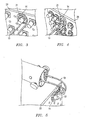
- FIGS. 3 - 5 are isometric views of various embodiments of coils for the tool of FIG. 1 in operation and are constructed in accordance with the invention
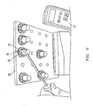
- FIG. 6 is an isometric view of one embodiment of a temperature probe in operation and is constructed in accordance with the invention.
- FIG. 7 is a sectional side view of a nutplate mounted to a composite substrate
- FIGS. 8 and 9 are top views of a nutplate before and after being removed from a composite substrate with a scraper in accordance with the invention.
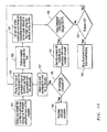
- FIG. 10 is a high level flow diagram of one embodiment of a method in accordance with the invention.
- FIGS. 11 and 12 are sectional side views of alternate embodiments of a system, tool and method constructed in accordance with the invention.
- FIG. 1 depicts one embodiment of a heating element or tool 11 that comprises part of a kit or system for use with a method or process of the invention.
- the kit may include tool 11, a plurality of removable and interchangeable coils 13 (e.g., six shown in FIG. 2 ) that are pre-formed to fit the most common nutplate types and sizes, a surface temperature probe 15 and thermometer 17 ( FIG. 6 ), and a plastic scraper 19 ( FIGS. 8 and 9 ) to avoid damaging the underlying structure.
- the kit may contain multiple coil sizes, one designed for each nutplate size (e.g., -3 through -6) and type (e.g., open, domed).
- the heating element 11 may comprise, for example, a modified version of a tool known as a Mim-Ductor, which is sold commercially by Induction Innovations, Inc.
- the tool 11 is a handheld, induction heating device that is used to heat fastener components (see, e.g., nutplates 21 in FIGS. 3, 4 and 7 ), underlying substrates 23 (e.g., composite substrates) and the adhesive 25 that bonds them, prior to separation.
- the tool is modified with a time delay relay to deliver short, intermittent heated pulses (e.g., five seconds each) that are followed by brief, non-heated wait periods (e.g., four seconds each). Both the pulse time and the wait time are adjustable for different applications.
- the tool may be provided with a switch or trigger 30 and a signal light 31 (e.g., an LED) to notify the operator when the tool 11 is delivering a heated pulse.
- a signal light 31 e.g., an LED
- the operator initially selects one of the coils 13 (see, e.g., FIG. 2 ) that closely fits around the adhesive base 25 of the nutplate 21 to be removed (step 101 in FIG. 10 ). For example, compare the sizes of the various loops 14 on coils 13 in FIG. 2 . A coil 13 with a loop 14 is selected so that it is just large enough to fit around the adhesive base 25 of the nutplate 21. For each nutplate 21, the coil loop 14 is selected that best fits, even if that coil is designed for another nutplate size and/or type.
- the coils may be provided with double loops.
- the coil loop 14 should not interfere with surrounding nutplates 21 or structure so that it can be as flush as possible with the surface of the composite substrate 23 (step 103). Heating will be less effective if the coil loop is not held flush with the surface. In areas where the nutplate 21 cannot be easily accessed from the front side (see, e.g., FIG. 5 ), the leads of the coil 13 may be bent back 180 degrees to access the nutplate 21 from the back side of the composite 23. To extend the life of the coil 13, a large bend radius should be used.
- the straight leads of one coil 13 are installed or inserted into the tool 11 (see, e.g., FIG. 5 ), and the loop 14 on the end of the coil 13 is placed around the adhesive base 25 of the nutplate 21, flush with the substrate 23 (see, e.g., FIGS. 3 - 5 ).
- Short pulses of power are delivered to the loop 14 via the tool 11 (stop 105), which heats the target nutplate 21, substrate 23 and adhesive bond 25 by induction with a magnetic field.
- the temperature of the substrate 23 may be monitored with a surface thermocouple probe 15 ( FIG. 6 ). See, e.g., step 107 in FIG. 10 .
- the adhesive 25 is sufficiently softened such that the nutplate 21 and adhesive 25 can be easily scraped off with the plastic scraper 19 (step 111).
- a single pulse of heat may be delivered by pressing and releasing the trigger button 30 ( FIG. 1 ) on tool 11. This action initiates, for example, a five-second pulse of heat.
- the LED indicator 31 is illuminated whenever the tool 11 is delivering a pulse. Consecutive pulses may be delivered by pressing and holding the trigger button 30. The tool 11 then cycles between five-second pulses and four-second "off' periods until the button 30 is released.
- the tip of the surface temperature probe 15 should be placed on the composite surface 23 just outside the adhesive base 25 of the nutplate 21. If the nutplate 21 is near an edge of the part, the temperature on the side closest to the edge of the part should be measured. This area is where the temperature will be hottest. Multiple spots on the composite 23 should be probed to find the highest temperature.
- the operator should stop heating when the temperature of the composite reaches or exceeds about 200°F, or after about 12 pulses (e.g., step 113), whichever comes first.
- the allowable range for removal is approximately 175 - 225°F, and should not exceed the maximum allowable temperature for the substrate material.
- the operator should apply heat for a limited number of cycles to prevent the tool from overheating (e.g., step 114). If after about 12 pulses the temperature, has not reached 200°F but is at least about 175°F, the operator should still attempt, to scrape off the nutplate 21 and adhesive 25, in some embodiments.
- the scraper 19 is preferably non-metallic to avoid damage to the composite substrates.
- the edge of the scraper 19 is placed flush with the composite surface 23 at the edge of the adhesive base 25.
- the adhesive base 25 and nutplate 21 are then simultaneously scraped off. If heated properly, the adhesive and nutplate should scrape off with a moderate amount of pressure. Larger nutplates (e.g., sizes -5 and -6) may require greater pressure. For larger nutplates it may be easier to first knock off the heated nutplate then scrape the adhesive base. Multiple passes with the scraper may be required to remove as much adhesive as possible. Since composite parts cool quickly, scraping should be finished within about 5 to 10 seconds of heating (step 119). If all adhesive is not removed with the nutplate on the first attempt (step 115), the composite and adhesive may be reheated after cooling (step 117) and scraped by the same process.
- FIGS. 11 and 12 illustrate alternate embodiments of the invention for still other types of applications where the bonded part (e.g., the stud, nutplate, etc.) and/or the substrate are not easily heated by induction.
- an adapter or extender 31 may be used to facilitate part removal.
- the extender 31 may be formed from a material that is readily heated by induction, such as an iron-based metal (e.g., steel).
- the extender is formed from a single piece of material, and may be formed in a shape that is complementary to the target component to be removed (e.g., cylindrical in the case of the stud extender 31).
- the extender 31 may be mounted directly to the bonded part, e.g., stud 33 in FIG. 11 ,
- the loop 14 of the coil 13 is placed around the extender 31, and the extender 31 and substrate 23 are heated by induction. Heat is transferred from the extender 31 to the bonded part 33 and adhesive base 33 by conduction until the target temperature for removal is reached.
- the extender 31 may incorporate internal threads such that it can be threaded onto the stud 33.
- the base of the extender 31 is configured in shape and size to make direct contact with the entire base of the stud 33, nutplate, etc.
- the extender 31 need not encapsulate the entire fastener component.
- the primary objective is to heat the adhesive 35 at the extended base of the stud 33. Heating the top of the fastener component is not necessarily required.
- FIG. 12 depicts an embodiment of the extender 41 for a domed nutplate 43 that is bonded with adhesive 45 to suhstrate 23.
- the features and advantages of the invention described herein apply equally to this embodiment.
- the internal and lower surfaces of the extender 41 may be configured complementary in shape and form to the target part 43 to be removed.
- the invention has numerous advantages. Temperature measurement with the invention is simpler and more accurate than that provided by prior art techniques. Thermocouples no longer need to be installed at the bond line of the adhesive; rather, the quick-response surface temperature probe is simply pressed against the composite surface between the heated pulses. Also, unlike prior art techniques, there is no excess hot air discharged on the probe to distort its temperature readings. No silicone or metallic masking or shielding is required since heating is isolated to within the loop of the coil. Heating of surrounding nutplates and structure is negligible, so the surrounding structure is unlikely to be damaged and is not a safety hazard.
- the invention also reduces the overall process for nutplate removal to only a few minutes.
- prior art techniques require a much longer and extensive set up for installation of thermocouple, fabrication of shielding, and require more time for heating by hot air.
- the invention exposes the composite substrate to high temperatures for a shorter period of time than with hot air, thereby making damage to the composite less likely.
- the handheld tool and flexible coils can preach and heat fasteners in tight or limited access locations where a hot air gun cannot reach,
- the invention is helpful for the removal of fastener elements from composite, metal and other forms of substrates in some applications, and for the removal of other small bonded parts, such as studs, standoffs, mounts, cable ties, bushings, inserts, etc.
Landscapes
- Physics & Mathematics (AREA)
- Electromagnetism (AREA)
- General Induction Heating (AREA)
- Automatic Assembly (AREA)
- Electric Connection Of Electric Components To Printed Circuits (AREA)
Abstract
Description
- This application claims priority to and the benefit of: 1)
U.S. Pat. App. No. 61/207,867, filed December 29, 2008 U.S. Pat. App. No. 12/407,005, filed March 19, 2009 - The present invention relates in general to removing components from structural assemblies and, in particular, to an improved system, method and apparatus for pulsed induction heat removal of adhesively-bonded components from structural assemblies.
- In some industrial applications, the parts used to build structural assemblies are formed from different types of materials. These parts may be joined or fastened together in various ways including, for example, conventional nuts and bolts, nutplates that are secured with adhesives, or still other types of fasteners or other assembly elements known by those of ordinary skill in the art.
- It is sometimes necessary to remove fasteners or assembly elements, such as to replace incorrect installations or rework the components. Some parts can be damaged during such procedures. For example, substrates formed from composite materials may be damaged by the removal of nutplates or other assembly elements that are bonded to them with strong adhesives. One technique for removing elements from substrates involves physically striking or knocking off the elements from the underlying structure or substrate. When such blows are inflicted at room temperature, they can cause delamination of the composite material In addition, composite parts can be damaged when personnel use power grinders to removed the residual adhesive left behind on the underlying structure after removal of the elements.
- Another technique for removal of sdhesively-bonded assembly elements uses a hot air gun to heat the parts and substrate. Prior to heating, thermocouples are installed close to the bond line of the adhesive, and custom-cut silicone masking is installed around the removal site to shield the surrounding elements from the hot air. Some manufacturers of fastener elements, e.g., Click Bond, Inc., also provide removal techniques. Although each of these solutions is workable for some applications, an improved system, method and apparatus for removal of assembly elements from structural assemblies would be desirable.
- Embodiments of a system, method and apparatus for pulsed induction heat removal of assembly elements from structures are disclosed. In one embodiment, the invention comprises a kit containing a heating element, a plurality of removable and interchangeable coils that are pre-formed to fit many types and sizes of fastener elements, a surface temperature probe and thermometer, and a non-metallic scraper to avoid damaging the structural assemblies during removal of the fastener elements and residual adhesive.
- In one embodiment, the heating element may comprise a modified, handheld induction heating tool that is used to heat the target element and substrate prior to removal of the element. The tool has a time delay relay to deliver short, intermittent heated pulses that are followed by brief, non-heated wait periods. This cycle reduces the likelihood of overheating the components and allows time for the operator to measure the temperature between the heated pulses. The tool also has a signal light to notify the operator when the tool is delivering a heated pulse.
- In one embodiment of a method of the invention, the operator initially selects one of the coils that closely fits around the adhesive base of the element to be removed. The leads of the coil are installed or inserted into the tool, and the loop on the end of the coil is placed around the adhesive base of the element, substantially flush with the underlying substrate. Short pulses off power are then delivered to the loop via the tool, which heats the target element and substrate by induction. The temperature of the substrate may be monitored with a surface thermocouple probe. When the substrate reaches the target temperature, the adhesive is sufficiently softened such that the component and adhesive are easily scraped off. The invention is helpful for the removal of fastener elements from composite, metal and other forms of substrates in some applications, and for the removal of other small bonded parts, such as studs, standoffs, mounts, cable ties, bushings, inserts, etc.
- The foregoing and other objects and advantages of the present invention will be apparent to those skilled in the art, in view of the following detailed description of the present invention, taken in conjunction with the appended claims and the accompanying drawings.
- According to a first aspect of the invention, we provide a method of removing a component that is adhesively bonded to a substrate, comprising (a) providing a tool with pulsed induction heating and a selection of coils that are mountable to the tool, (b) selecting one of the coils having a loop that fits around an adhesive base of the component to be removed from the substrate, (c) inserting leads of the selected coil into the tool and positioning the loop around the component, adjacent to a surface of the substrate, (d) pulsing the tool to heat the component, substrate and adhesive, (e) detecting a temperature of the substrate, (f) repeating steps (d) and (e) until the substrate reaches a target temperature and the adhesive is softened, and then (g) scraping the component and adhesive from the substrate.
- Step (d) may comprise depressing and releasing a trigger on the tool to deliver a single pulse of heat to the coil.
- Step (d) may comprise depressing and holding a trigger on the tool to deliver multiple pulses of heat to the coil.
- Step (d) may comprise pulsing the coil for approximately five-second pulses of heat, each of which may be interrupted by approximately four-second, non-heated wait periods until the trigger is released.
- Step (e) may comprise positioning a tip of a surface temperature probe on the substrate just outside of the adhesive.
- Step (f) may comprise terminating heating of the substrate when a temperature thereof reaches or exceeds about 200°F, or after about 12 pulses of heat, whichever comes first.
- A temperature range for the substrate may be approximately 175 - 225°F, not to exceed a maximum allowable temperature for the substrate material.
- Step (g) may comprise completing scraping within about 5 to 10 seconds of step (f).
- The method may further comprise cooling the substrate if the adhesive is not removed with the component after step (g).
- Step (c) may further comprise mounting an extender directly to the component, between the loop and the component, such that the loop inductively heats the extender.
- The extender may be formed from a material that is readily heated by induction, the extender being formed from a single piece of material, and the extender having lower and inner surfaces that are complementary in shape to the component.
- So that the manner in which the features and advantages of the present invention are attained and can be understood in more detail, a more particular description of the invention briefly summarized above may be had by reference to the embodiments thereof that are illustrated in the appended drawings. However, the drawings illustrate only some embodiment of the invention and therefore are not to be considered limiting of its scope as the invention may admit to other equally effective embodiments.
-
FIG. 1 is an exploded isometric view of one embodiment of a tool constructed in accordance with the invention; -
FIG. 2 is an isometric view depicting various embodiments of coils for the tool ofFIG. 1 and is constructed in accordance with the invention; -
FIGS. 3 - 5 are isometric views of various embodiments of coils for the tool ofFIG. 1 in operation and are constructed in accordance with the invention; -
FIG. 6 is an isometric view of one embodiment of a temperature probe in operation and is constructed in accordance with the invention; -
FIG. 7 is a sectional side view of a nutplate mounted to a composite substrate; -
FIGS. 8 and 9 are top views of a nutplate before and after being removed from a composite substrate with a scraper in accordance with the invention; -
FIG. 10 is a high level flow diagram of one embodiment of a method in accordance with the invention; and -
FIGS. 11 and 12 are sectional side views of alternate embodiments of a system, tool and method constructed in accordance with the invention. - Referring to
FIGS. 1 - 12 , embodiments of a system, method and apparatus for pulsed induction heat removal of assembly elements from structures are disclosed.FIG. 1 depicts one embodiment of a heating element ortool 11 that comprises part of a kit or system for use with a method or process of the invention. The kit may includetool 11, a plurality of removable and interchangeable coils 13 (e.g., six shown inFIG. 2 ) that are pre-formed to fit the most common nutplate types and sizes, asurface temperature probe 15 and thermometer 17 (FIG. 6 ), and a plastic scraper 19 (FIGS. 8 and 9 ) to avoid damaging the underlying structure. The kit may contain multiple coil sizes, one designed for each nutplate size (e.g., -3 through -6) and type (e.g., open, domed). - The
heating element 11 may comprise, for example, a modified version of a tool known as a Mim-Ductor, which is sold commercially by Induction Innovations, Inc. Thetool 11 is a handheld, induction heating device that is used to heat fastener components (see, e.g.,nutplates 21 inFIGS. 3, 4 and7 ), underlying substrates 23 (e.g., composite substrates) and theadhesive 25 that bonds them, prior to separation. The tool is modified with a time delay relay to deliver short, intermittent heated pulses (e.g., five seconds each) that are followed by brief, non-heated wait periods (e.g., four seconds each). Both the pulse time and the wait time are adjustable for different applications. This cycle reduces the likelihood of overheating the underlyingsubstrate 23 and allows time for the operator to measure the temperature between the heated pulses. As shown inFIG. 1 . the tool may be provided with a switch or trigger 30 and a signal light 31 (e.g., an LED) to notify the operator when thetool 11 is delivering a heated pulse. - In one embodiment of a method of the invention (see, e.g.,
FIG. 10 ), the operator initially selects one of the coils 13 (see, e.g.,FIG. 2 ) that closely fits around theadhesive base 25 of thenutplate 21 to be removed (step 101 inFIG. 10 ). For example, compare the sizes of thevarious loops 14 oncoils 13 inFIG. 2 . Acoil 13 with aloop 14 is selected so that it is just large enough to fit around theadhesive base 25 of thenutplate 21. For each nutplate 21, thecoil loop 14 is selected that best fits, even if that coil is designed for another nutplate size and/or type. The coils may be provided with double loops. Thecoil loop 14 should not interfere with surroundingnutplates 21 or structure so that it can be as flush as possible with the surface of the composite substrate 23 (step 103). Heating will be less effective if the coil loop is not held flush with the surface. In areas where thenutplate 21 cannot be easily accessed from the front side (see, e.g.,FIG. 5 ), the leads of thecoil 13 may be bent back 180 degrees to access thenutplate 21 from the back side of the composite 23. To extend the life of thecoil 13, a large bend radius should be used. - The straight leads of one
coil 13 are installed or inserted into the tool 11 (see, e.g.,FIG. 5 ), and theloop 14 on the end of thecoil 13 is placed around theadhesive base 25 of thenutplate 21, flush with the substrate 23 (see, e.g.,FIGS. 3 - 5 ). Short pulses of power are delivered to theloop 14 via the tool 11 (stop 105), which heats thetarget nutplate 21,substrate 23 andadhesive bond 25 by induction with a magnetic field. The temperature of thesubstrate 23 may be monitored with a surface thermocouple probe 15 (FIG. 6 ). See, e.g.,step 107 inFIG. 10 . When thesubstrate 23 reaches the target temperature (step 109), the adhesive 25 is sufficiently softened such that thenutplate 21 and adhesive 25 can be easily scraped off with the plastic scraper 19 (step 111). - A single pulse of heat may be delivered by pressing and releasing the trigger button 30 (
FIG. 1 ) ontool 11. This action initiates, for example, a five-second pulse of heat. TheLED indicator 31 is illuminated whenever thetool 11 is delivering a pulse. Consecutive pulses may be delivered by pressing and holding thetrigger button 30. Thetool 11 then cycles between five-second pulses and four-second "off' periods until thebutton 30 is released. - During temperature measurement (see, e.g.,
FIG. 6 ), the tip of thesurface temperature probe 15 should be placed on thecomposite surface 23 just outside theadhesive base 25 of thenutplate 21. If thenutplate 21 is near an edge of the part, the temperature on the side closest to the edge of the part should be measured. This area is where the temperature will be hottest. Multiple spots on the composite 23 should be probed to find the highest temperature. - In one embodiment, the operator should stop heating when the temperature of the composite reaches or exceeds about 200°F, or after about 12 pulses (e.g., step 113), whichever comes first. The allowable range for removal is approximately 175 - 225°F, and should not exceed the maximum allowable temperature for the substrate material. The operator should apply heat for a limited number of cycles to prevent the tool from overheating (e.g., step 114). If after about 12 pulses the temperature, has not reached 200°F but is at least about 175°F, the operator should still attempt, to scrape off the
nutplate 21 and adhesive 25, in some embodiments. - Referring again to
FIGS. 8 and 9 , thescraper 19 is preferably non-metallic to avoid damage to the composite substrates. The edge of thescraper 19 is placed flush with thecomposite surface 23 at the edge of theadhesive base 25. Theadhesive base 25 andnutplate 21 are then simultaneously scraped off. If heated properly, the adhesive and nutplate should scrape off with a moderate amount of pressure. Larger nutplates (e.g., sizes -5 and -6) may require greater pressure. For larger nutplates it may be easier to first knock off the heated nutplate then scrape the adhesive base. Multiple passes with the scraper may be required to remove as much adhesive as possible. Since composite parts cool quickly, scraping should be finished within about 5 to 10 seconds of heating (step 119). If all adhesive is not removed with the nutplate on the first attempt (step 115), the composite and adhesive may be reheated after cooling (step 117) and scraped by the same process. -
FIGS. 11 and 12 illustrate alternate embodiments of the invention for still other types of applications where the bonded part (e.g., the stud, nutplate, etc.) and/or the substrate are not easily heated by induction. For these types of applications, an adapter orextender 31 may be used to facilitate part removal. Theextender 31 may be formed from a material that is readily heated by induction, such as an iron-based metal (e.g., steel). In some embodiments, the extender is formed from a single piece of material, and may be formed in a shape that is complementary to the target component to be removed (e.g., cylindrical in the case of the stud extender 31). - The
extender 31 may be mounted directly to the bonded part, e.g.,stud 33 inFIG. 11 , Theloop 14 of thecoil 13 is placed around theextender 31, and theextender 31 andsubstrate 23 are heated by induction. Heat is transferred from theextender 31 to the bondedpart 33 andadhesive base 33 by conduction until the target temperature for removal is reached. In the case of bonded stud 33 (e.g.,FIG. 11 ), theextender 31 may incorporate internal threads such that it can be threaded onto thestud 33. For improved heat transfer, the base of theextender 31 is configured in shape and size to make direct contact with the entire base of thestud 33, nutplate, etc. Theextender 31 need not encapsulate the entire fastener component. The primary objective is to heat the adhesive 35 at the extended base of thestud 33. Heating the top of the fastener component is not necessarily required. -
FIG. 12 depicts an embodiment of the extender 41 for adomed nutplate 43 that is bonded with adhesive 45 tosuhstrate 23. The features and advantages of the invention described herein apply equally to this embodiment. Again, the internal and lower surfaces of the extender 41 may be configured complementary in shape and form to thetarget part 43 to be removed. - The invention has numerous advantages. Temperature measurement with the invention is simpler and more accurate than that provided by prior art techniques. Thermocouples no longer need to be installed at the bond line of the adhesive; rather, the quick-response surface temperature probe is simply pressed against the composite surface between the heated pulses. Also, unlike prior art techniques, there is no excess hot air discharged on the probe to distort its temperature readings. No silicone or metallic masking or shielding is required since heating is isolated to within the loop of the coil. Heating of surrounding nutplates and structure is negligible, so the surrounding structure is unlikely to be damaged and is not a safety hazard.
- The invention also reduces the overall process for nutplate removal to only a few minutes. In contrast, prior art techniques require a much longer and extensive set up for installation of thermocouple, fabrication of shielding, and require more time for heating by hot air. By using induction heating, the invention exposes the composite substrate to high temperatures for a shorter period of time than with hot air, thereby making damage to the composite less likely. The handheld tool and flexible coils can preach and heat fasteners in tight or limited access locations where a hot air gun cannot reach, The invention is helpful for the removal of fastener elements from composite, metal and other forms of substrates in some applications, and for the removal of other small bonded parts, such as studs, standoffs, mounts, cable ties, bushings, inserts, etc.
- While the invention has been shown or described in only some of its forms, it should be apparent to those skilled in the art that it is not so limited, but is susceptible to various changes without departing from the scope of the invention.
Claims (11)
- A method of removing a component that is adhesively bonded to a substrate, comprising:(a) providing a tool with pulsed induction heating and a selection of coils that are mountable to the tool;(b) selecting one of the coils having a loop that fits around an adhesive base of the component to be removed from the substrate;(c) inserting leads of the selected coil into the tool and positioning the loop around the component, adjacent to a surface of the substrate;(d) pulsing the tool to heat the component, substrate and adhesive;(e) detecting a temperature of the substrate;(f) repeating steps (d) and (e) until the substrate reaches a target temperature and the adhesive is softened; and then(g) scraping the component and adhesive from the substrate.
- A method according to Claim 1, wherein step (d) comprises depressing and releasing a trigger on the tool to deliver a single pulse of heat to the coil.
- A method according to Claim 1, wherein step (d) comprises depressing and holding a trigger on the tool to deliver multiple pulses of heat to the coil.
- A method according to Claim 3, wherein step (d) comprises pulsing the coil for approximately five-second pulses of heat, each of which is interrupted by approximately four-second, non-heated wait periods until the trigger is released.
- A method according to any one of the preceding claims, wherein step (e) comprises positioning a tip of a surface temperature probe on the substrate just outside of the adhesive.
- A method according to any one of the preceding claims, wherein step (f) comprises terminating heating of the substrate when a temperature thereof reaches or exceeds about 200°F, or after about 12 pulses of heat, whichever comes first.
- A method according to Claim 6, wherein a temperature range for the substrate is approximately 175 - 225°F, not to exceed a maximum allowable temperature for the substrate material.
- A method according to any one of the preceding claims, wherein step (g) comprise completing scraping within about 5 to 10 seconds of step (f).
- A method according to Claim 8, further comprising cooling the substrate if the adhesive is not removed with the component after step (g).
- A method according to any one of the preceding claims, wherein step (c) further comprises mounting an extender directly to the component, between the loop and the component, such that the loop inductively heats the extender.
- A method according to Claim 10, wherein the extender is formed from a material that is readily heated by induction, the extender is formed from a single piece of material, and the extender has lower and inner surfaces that are complementary in shape to the component.
Applications Claiming Priority (2)
| Application Number | Priority Date | Filing Date | Title |
|---|---|---|---|
| US20786708P | 2008-12-29 | 2008-12-29 | |
| US12/407,005 US9402282B2 (en) | 2008-12-29 | 2009-03-19 | System, method and apparatus for pulsed induction heat removal of components from structural assemblies |
Publications (2)
| Publication Number | Publication Date |
|---|---|
| EP2205042A1 true EP2205042A1 (en) | 2010-07-07 |
| EP2205042B1 EP2205042B1 (en) | 2012-06-13 |
Family
ID=42026166
Family Applications (1)
| Application Number | Title | Priority Date | Filing Date |
|---|---|---|---|
| EP09180743A Not-in-force EP2205042B1 (en) | 2008-12-29 | 2009-12-24 | System, method and apparatus for pulsed induction heat removal of components from structural assemblies |
Country Status (8)
| Country | Link |
|---|---|
| US (1) | US9402282B2 (en) |
| EP (1) | EP2205042B1 (en) |
| JP (1) | JP5632159B2 (en) |
| KR (1) | KR101629014B1 (en) |
| AU (1) | AU2009251164B2 (en) |
| CA (1) | CA2689184A1 (en) |
| DK (1) | DK2205042T3 (en) |
| ES (1) | ES2385284T3 (en) |
Cited By (2)
| Publication number | Priority date | Publication date | Assignee | Title |
|---|---|---|---|---|
| EP2809127A1 (en) * | 2013-05-28 | 2014-12-03 | IDTools B.V. | Induction heating tool and method for assembling a front module to an induction heating tool |
| US10349470B2 (en) * | 2015-10-29 | 2019-07-09 | Sarge Holdings Company, LLC | Portable induction heater |
Families Citing this family (5)
| Publication number | Priority date | Publication date | Assignee | Title |
|---|---|---|---|---|
| US20160014851A1 (en) * | 2014-07-14 | 2016-01-14 | Sarge Holding Co., LLC | Induction heater coil accessory |
| US20170118804A1 (en) * | 2015-10-23 | 2017-04-27 | Z PRODUX, Inc | Inductive Cosmetic Depotting Device and Method |
| US11229089B2 (en) * | 2016-05-18 | 2022-01-18 | Physical Systems, Inc. | Self fixturing heater and method for accelerating nutplate adhesive curing |
| US11039507B2 (en) * | 2017-02-23 | 2021-06-15 | General Electric Company | Method of brazing a treatment area of a load-bearing component |
| US12356530B1 (en) * | 2024-06-04 | 2025-07-08 | General Electric Company | Method of removing an insert from a substrate |
Citations (3)
| Publication number | Priority date | Publication date | Assignee | Title |
|---|---|---|---|---|
| US4690724A (en) * | 1986-04-24 | 1987-09-01 | Outlaw William F | Electrically heated decal stripping tool |
| US6563096B1 (en) * | 2000-11-27 | 2003-05-13 | Pacholok David R | Eddy current/hysteretic heater apparatus and method of use |
| US20040099659A1 (en) * | 1997-02-28 | 2004-05-27 | Johnson Robert H. | Adhesive or sealant composition including high efficiency heating agents and methods of use |
Family Cites Families (10)
| Publication number | Priority date | Publication date | Assignee | Title |
|---|---|---|---|---|
| US3428769A (en) * | 1966-07-26 | 1969-02-18 | Mc Donnell Douglas Corp | Induction heating tool |
| US3593001A (en) * | 1969-12-31 | 1971-07-13 | Nasa | Stud-bonding gun |
| US4055744A (en) * | 1975-07-16 | 1977-10-25 | Fortune William S | Electrically heated soldering-desoldering instruments |
| US5079791A (en) * | 1989-06-26 | 1992-01-14 | Grech George J | Tool for snap fasteners |
| US5374809A (en) * | 1993-05-12 | 1994-12-20 | The United States Of America As Represented By The Administrator Of The National Aeronautics And Space Administration | Induction heating coupler and annealer |
| US6038754A (en) * | 1997-12-15 | 2000-03-21 | Fairchild Holding Corp. | Nut removal and installation tool |
| US6559428B2 (en) * | 2001-01-16 | 2003-05-06 | General Electric Company | Induction heating tool |
| CA2392078C (en) * | 1999-11-03 | 2005-02-22 | Nexicor Llc | Hand held induction tool |
| US20060075617A1 (en) * | 2004-10-07 | 2006-04-13 | Toosky Rahmatollah F | Performance enhancing repair tool |
| US7705272B2 (en) * | 2006-08-03 | 2010-04-27 | Power House Tool, Inc. | Bolt heater assembly unit having junction housing configuration |
-
2009
- 2009-03-19 US US12/407,005 patent/US9402282B2/en active Active
- 2009-12-23 CA CA2689184A patent/CA2689184A1/en not_active Abandoned
- 2009-12-23 AU AU2009251164A patent/AU2009251164B2/en not_active Ceased
- 2009-12-24 EP EP09180743A patent/EP2205042B1/en not_active Not-in-force
- 2009-12-24 DK DK09180743.8T patent/DK2205042T3/en active
- 2009-12-24 ES ES09180743T patent/ES2385284T3/en active Active
- 2009-12-28 JP JP2009297092A patent/JP5632159B2/en not_active Expired - Fee Related
- 2009-12-29 KR KR1020090132545A patent/KR101629014B1/en not_active Expired - Fee Related
Patent Citations (3)
| Publication number | Priority date | Publication date | Assignee | Title |
|---|---|---|---|---|
| US4690724A (en) * | 1986-04-24 | 1987-09-01 | Outlaw William F | Electrically heated decal stripping tool |
| US20040099659A1 (en) * | 1997-02-28 | 2004-05-27 | Johnson Robert H. | Adhesive or sealant composition including high efficiency heating agents and methods of use |
| US6563096B1 (en) * | 2000-11-27 | 2003-05-13 | Pacholok David R | Eddy current/hysteretic heater apparatus and method of use |
Cited By (3)
| Publication number | Priority date | Publication date | Assignee | Title |
|---|---|---|---|---|
| EP2809127A1 (en) * | 2013-05-28 | 2014-12-03 | IDTools B.V. | Induction heating tool and method for assembling a front module to an induction heating tool |
| WO2014193225A1 (en) * | 2013-05-28 | 2014-12-04 | Id Tools B.V. | Induction heating tool and method for assembling a front module to an induction heating tool |
| US10349470B2 (en) * | 2015-10-29 | 2019-07-09 | Sarge Holdings Company, LLC | Portable induction heater |
Also Published As
| Publication number | Publication date |
|---|---|
| US20100237054A1 (en) | 2010-09-23 |
| JP5632159B2 (en) | 2014-11-26 |
| JP2010155341A (en) | 2010-07-15 |
| US9402282B2 (en) | 2016-07-26 |
| ES2385284T3 (en) | 2012-07-20 |
| AU2009251164B2 (en) | 2015-04-16 |
| KR20100080426A (en) | 2010-07-08 |
| EP2205042B1 (en) | 2012-06-13 |
| CA2689184A1 (en) | 2010-06-29 |
| DK2205042T3 (en) | 2012-09-24 |
| KR101629014B1 (en) | 2016-06-09 |
| AU2009251164A1 (en) | 2010-07-15 |
Similar Documents
| Publication | Publication Date | Title |
|---|---|---|
| EP2205042B1 (en) | System, method and apparatus for pulsed induction heat removal of components from structural assemblies | |
| US7679032B2 (en) | Soldering or desoldering iron | |
| KR101876776B1 (en) | System and method for testing of bonds of a semiconductor assembly | |
| US20070144653A1 (en) | Methods and systems for debonding substrates | |
| TW200832583A (en) | In-situ wafer temperature measurement and control | |
| EP1794462B1 (en) | Affixing an anchor in a drilled hole | |
| CN102939161A (en) | A non contact real time micro polymerase chain reaction system and method thereof | |
| KR20110126050A (en) | Junction Test System and Method of Semiconductor Assembly | |
| WO2007093744A3 (en) | Method and device for characterizing, using active pyrometry, a thin-layer material arranged on a substrate | |
| JPH09502405A (en) | Butt welding equipment for plastic joints, especially pipes | |
| JP4930713B2 (en) | Thermal cycle test apparatus and thermal cycle test method | |
| KR101340424B1 (en) | AlN hot plate for high temperature processing | |
| US20130133770A1 (en) | Apparatus and method for repairing damaged pipes | |
| EP3199294A1 (en) | System and method for fixing/detaching parts on a machine tool via a reversible adhesive, and use of said reversible adhesive | |
| US20160263638A1 (en) | Temperature Measurement Device for Metal Sheet | |
| EP2896943A1 (en) | Temperature sensor for sensing a temperature of a cooking pot | |
| JP2005030792A (en) | Temperature measuring wafer | |
| JP2006142443A (en) | Shrink fit device and heating method | |
| US20220334320A1 (en) | Optical fiber installation tool | |
| JP2006314761A (en) | Method for casting restoration metallic material for dental use, electromagnetic wave heat generation furnace, and investing material | |
| JP2008086408A (en) | Standby device used for working tool for bone-joining plate | |
| Klausner et al. | Liquid crystal thermography in boiling heat transfer | |
| JP2006138870A (en) | Device for testing thermal shock | |
| PL164141B1 (en) | Method of connecting a heat output measuring system temperature sensors to spot-welder thin steel sheet radiators with build in temperature sensor for connection to a head output measuring system | |
| KR20050019593A (en) | Heating apparatus using electromagnetic inductive heating |
Legal Events
| Date | Code | Title | Description |
|---|---|---|---|
| PUAI | Public reference made under article 153(3) epc to a published international application that has entered the european phase |
Free format text: ORIGINAL CODE: 0009012 |
|
| AK | Designated contracting states |
Kind code of ref document: A1 Designated state(s): AT BE BG CH CY CZ DE DK EE ES FI FR GB GR HR HU IE IS IT LI LT LU LV MC MK MT NL NO PL PT RO SE SI SK SM TR |
|
| AX | Request for extension of the european patent |
Extension state: AL BA RS |
|
| 17P | Request for examination filed |
Effective date: 20101027 |
|
| GRAP | Despatch of communication of intention to grant a patent |
Free format text: ORIGINAL CODE: EPIDOSNIGR1 |
|
| RIC1 | Information provided on ipc code assigned before grant |
Ipc: H05B 6/02 20060101AFI20111214BHEP Ipc: H05B 6/36 20060101ALI20111214BHEP Ipc: H05B 6/14 20060101ALI20111214BHEP Ipc: H05B 6/40 20060101ALI20111214BHEP |
|
| GRAS | Grant fee paid |
Free format text: ORIGINAL CODE: EPIDOSNIGR3 |
|
| GRAA | (expected) grant |
Free format text: ORIGINAL CODE: 0009210 |
|
| AK | Designated contracting states |
Kind code of ref document: B1 Designated state(s): AT BE BG CH CY CZ DE DK EE ES FI FR GB GR HR HU IE IS IT LI LT LU LV MC MK MT NL NO PL PT RO SE SI SK SM TR |
|
| REG | Reference to a national code |
Ref country code: GB Ref legal event code: FG4D |
|
| REG | Reference to a national code |
Ref country code: AT Ref legal event code: REF Ref document number: 562476 Country of ref document: AT Kind code of ref document: T Effective date: 20120615 Ref country code: CH Ref legal event code: EP |
|
| REG | Reference to a national code |
Ref country code: IE Ref legal event code: FG4D |
|
| REG | Reference to a national code |
Ref country code: ES Ref legal event code: FG2A Ref document number: 2385284 Country of ref document: ES Kind code of ref document: T3 Effective date: 20120720 |
|
| REG | Reference to a national code |
Ref country code: NL Ref legal event code: T3 |
|
| REG | Reference to a national code |
Ref country code: DE Ref legal event code: R096 Ref document number: 602009007544 Country of ref document: DE Effective date: 20120809 |
|
| REG | Reference to a national code |
Ref country code: DK Ref legal event code: T3 |
|
| REG | Reference to a national code |
Ref country code: NO Ref legal event code: T2 Effective date: 20120613 |
|
| PG25 | Lapsed in a contracting state [announced via postgrant information from national office to epo] |
Ref country code: CY Free format text: LAPSE BECAUSE OF FAILURE TO SUBMIT A TRANSLATION OF THE DESCRIPTION OR TO PAY THE FEE WITHIN THE PRESCRIBED TIME-LIMIT Effective date: 20120613 Ref country code: LT Free format text: LAPSE BECAUSE OF FAILURE TO SUBMIT A TRANSLATION OF THE DESCRIPTION OR TO PAY THE FEE WITHIN THE PRESCRIBED TIME-LIMIT Effective date: 20120613 Ref country code: FI Free format text: LAPSE BECAUSE OF FAILURE TO SUBMIT A TRANSLATION OF THE DESCRIPTION OR TO PAY THE FEE WITHIN THE PRESCRIBED TIME-LIMIT Effective date: 20120613 Ref country code: SE Free format text: LAPSE BECAUSE OF FAILURE TO SUBMIT A TRANSLATION OF THE DESCRIPTION OR TO PAY THE FEE WITHIN THE PRESCRIBED TIME-LIMIT Effective date: 20120613 |
|
| REG | Reference to a national code |
Ref country code: AT Ref legal event code: MK05 Ref document number: 562476 Country of ref document: AT Kind code of ref document: T Effective date: 20120613 |
|
| REG | Reference to a national code |
Ref country code: LT Ref legal event code: MG4D Effective date: 20120613 |
|
| PG25 | Lapsed in a contracting state [announced via postgrant information from national office to epo] |
Ref country code: HR Free format text: LAPSE BECAUSE OF FAILURE TO SUBMIT A TRANSLATION OF THE DESCRIPTION OR TO PAY THE FEE WITHIN THE PRESCRIBED TIME-LIMIT Effective date: 20120613 Ref country code: SI Free format text: LAPSE BECAUSE OF FAILURE TO SUBMIT A TRANSLATION OF THE DESCRIPTION OR TO PAY THE FEE WITHIN THE PRESCRIBED TIME-LIMIT Effective date: 20120613 Ref country code: GR Free format text: LAPSE BECAUSE OF FAILURE TO SUBMIT A TRANSLATION OF THE DESCRIPTION OR TO PAY THE FEE WITHIN THE PRESCRIBED TIME-LIMIT Effective date: 20120914 Ref country code: LV Free format text: LAPSE BECAUSE OF FAILURE TO SUBMIT A TRANSLATION OF THE DESCRIPTION OR TO PAY THE FEE WITHIN THE PRESCRIBED TIME-LIMIT Effective date: 20120613 |
|
| PG25 | Lapsed in a contracting state [announced via postgrant information from national office to epo] |
Ref country code: IS Free format text: LAPSE BECAUSE OF FAILURE TO SUBMIT A TRANSLATION OF THE DESCRIPTION OR TO PAY THE FEE WITHIN THE PRESCRIBED TIME-LIMIT Effective date: 20121013 Ref country code: CZ Free format text: LAPSE BECAUSE OF FAILURE TO SUBMIT A TRANSLATION OF THE DESCRIPTION OR TO PAY THE FEE WITHIN THE PRESCRIBED TIME-LIMIT Effective date: 20120613 Ref country code: AT Free format text: LAPSE BECAUSE OF FAILURE TO SUBMIT A TRANSLATION OF THE DESCRIPTION OR TO PAY THE FEE WITHIN THE PRESCRIBED TIME-LIMIT Effective date: 20120613 Ref country code: EE Free format text: LAPSE BECAUSE OF FAILURE TO SUBMIT A TRANSLATION OF THE DESCRIPTION OR TO PAY THE FEE WITHIN THE PRESCRIBED TIME-LIMIT Effective date: 20120613 Ref country code: RO Free format text: LAPSE BECAUSE OF FAILURE TO SUBMIT A TRANSLATION OF THE DESCRIPTION OR TO PAY THE FEE WITHIN THE PRESCRIBED TIME-LIMIT Effective date: 20120613 Ref country code: SK Free format text: LAPSE BECAUSE OF FAILURE TO SUBMIT A TRANSLATION OF THE DESCRIPTION OR TO PAY THE FEE WITHIN THE PRESCRIBED TIME-LIMIT Effective date: 20120613 |
|
| PG25 | Lapsed in a contracting state [announced via postgrant information from national office to epo] |
Ref country code: PT Free format text: LAPSE BECAUSE OF FAILURE TO SUBMIT A TRANSLATION OF THE DESCRIPTION OR TO PAY THE FEE WITHIN THE PRESCRIBED TIME-LIMIT Effective date: 20121015 Ref country code: PL Free format text: LAPSE BECAUSE OF FAILURE TO SUBMIT A TRANSLATION OF THE DESCRIPTION OR TO PAY THE FEE WITHIN THE PRESCRIBED TIME-LIMIT Effective date: 20120613 |
|
| PLBE | No opposition filed within time limit |
Free format text: ORIGINAL CODE: 0009261 |
|
| STAA | Information on the status of an ep patent application or granted ep patent |
Free format text: STATUS: NO OPPOSITION FILED WITHIN TIME LIMIT |
|
| 26N | No opposition filed |
Effective date: 20130314 |
|
| REG | Reference to a national code |
Ref country code: DE Ref legal event code: R097 Ref document number: 602009007544 Country of ref document: DE Effective date: 20130314 |
|
| PG25 | Lapsed in a contracting state [announced via postgrant information from national office to epo] |
Ref country code: BG Free format text: LAPSE BECAUSE OF FAILURE TO SUBMIT A TRANSLATION OF THE DESCRIPTION OR TO PAY THE FEE WITHIN THE PRESCRIBED TIME-LIMIT Effective date: 20120913 Ref country code: MC Free format text: LAPSE BECAUSE OF NON-PAYMENT OF DUE FEES Effective date: 20121231 |
|
| REG | Reference to a national code |
Ref country code: IE Ref legal event code: MM4A |
|
| PG25 | Lapsed in a contracting state [announced via postgrant information from national office to epo] |
Ref country code: IE Free format text: LAPSE BECAUSE OF NON-PAYMENT OF DUE FEES Effective date: 20121224 |
|
| PG25 | Lapsed in a contracting state [announced via postgrant information from national office to epo] |
Ref country code: MT Free format text: LAPSE BECAUSE OF FAILURE TO SUBMIT A TRANSLATION OF THE DESCRIPTION OR TO PAY THE FEE WITHIN THE PRESCRIBED TIME-LIMIT Effective date: 20120613 |
|
| PG25 | Lapsed in a contracting state [announced via postgrant information from national office to epo] |
Ref country code: LU Free format text: LAPSE BECAUSE OF NON-PAYMENT OF DUE FEES Effective date: 20121224 Ref country code: SM Free format text: LAPSE BECAUSE OF FAILURE TO SUBMIT A TRANSLATION OF THE DESCRIPTION OR TO PAY THE FEE WITHIN THE PRESCRIBED TIME-LIMIT Effective date: 20120613 |
|
| PG25 | Lapsed in a contracting state [announced via postgrant information from national office to epo] |
Ref country code: HU Free format text: LAPSE BECAUSE OF FAILURE TO SUBMIT A TRANSLATION OF THE DESCRIPTION OR TO PAY THE FEE WITHIN THE PRESCRIBED TIME-LIMIT Effective date: 20091224 |
|
| REG | Reference to a national code |
Ref country code: CH Ref legal event code: PL |
|
| PG25 | Lapsed in a contracting state [announced via postgrant information from national office to epo] |
Ref country code: CH Free format text: LAPSE BECAUSE OF NON-PAYMENT OF DUE FEES Effective date: 20131231 Ref country code: LI Free format text: LAPSE BECAUSE OF NON-PAYMENT OF DUE FEES Effective date: 20131231 |
|
| PGFP | Annual fee paid to national office [announced via postgrant information from national office to epo] |
Ref country code: ES Payment date: 20141226 Year of fee payment: 6 Ref country code: DK Payment date: 20141230 Year of fee payment: 6 Ref country code: GB Payment date: 20141229 Year of fee payment: 6 |
|
| PGFP | Annual fee paid to national office [announced via postgrant information from national office to epo] |
Ref country code: NL Payment date: 20141226 Year of fee payment: 6 Ref country code: FR Payment date: 20141217 Year of fee payment: 6 |
|
| PGFP | Annual fee paid to national office [announced via postgrant information from national office to epo] |
Ref country code: IT Payment date: 20141220 Year of fee payment: 6 |
|
| PGFP | Annual fee paid to national office [announced via postgrant information from national office to epo] |
Ref country code: NO Payment date: 20141231 Year of fee payment: 6 Ref country code: DE Payment date: 20141230 Year of fee payment: 6 |
|
| PGFP | Annual fee paid to national office [announced via postgrant information from national office to epo] |
Ref country code: BE Payment date: 20141229 Year of fee payment: 6 |
|
| PG25 | Lapsed in a contracting state [announced via postgrant information from national office to epo] |
Ref country code: MK Free format text: LAPSE BECAUSE OF FAILURE TO SUBMIT A TRANSLATION OF THE DESCRIPTION OR TO PAY THE FEE WITHIN THE PRESCRIBED TIME-LIMIT Effective date: 20120613 |
|
| PGFP | Annual fee paid to national office [announced via postgrant information from national office to epo] |
Ref country code: TR Payment date: 20131224 Year of fee payment: 5 |
|
| PG25 | Lapsed in a contracting state [announced via postgrant information from national office to epo] |
Ref country code: BE Free format text: LAPSE BECAUSE OF NON-PAYMENT OF DUE FEES Effective date: 20151231 |
|
| REG | Reference to a national code |
Ref country code: DE Ref legal event code: R119 Ref document number: 602009007544 Country of ref document: DE |
|
| REG | Reference to a national code |
Ref country code: DK Ref legal event code: EBP Effective date: 20151231 |
|
| REG | Reference to a national code |
Ref country code: NO Ref legal event code: MMEP |
|
| GBPC | Gb: european patent ceased through non-payment of renewal fee |
Effective date: 20151224 |
|
| REG | Reference to a national code |
Ref country code: NL Ref legal event code: MM Effective date: 20160101 |
|
| REG | Reference to a national code |
Ref country code: FR Ref legal event code: ST Effective date: 20160831 |
|
| PG25 | Lapsed in a contracting state [announced via postgrant information from national office to epo] |
Ref country code: DE Free format text: LAPSE BECAUSE OF NON-PAYMENT OF DUE FEES Effective date: 20160701 Ref country code: NL Free format text: LAPSE BECAUSE OF NON-PAYMENT OF DUE FEES Effective date: 20160101 Ref country code: GB Free format text: LAPSE BECAUSE OF NON-PAYMENT OF DUE FEES Effective date: 20151224 Ref country code: NO Free format text: LAPSE BECAUSE OF NON-PAYMENT OF DUE FEES Effective date: 20151231 |
|
| PG25 | Lapsed in a contracting state [announced via postgrant information from national office to epo] |
Ref country code: FR Free format text: LAPSE BECAUSE OF NON-PAYMENT OF DUE FEES Effective date: 20151231 |
|
| PG25 | Lapsed in a contracting state [announced via postgrant information from national office to epo] |
Ref country code: IT Free format text: LAPSE BECAUSE OF NON-PAYMENT OF DUE FEES Effective date: 20151224 |
|
| REG | Reference to a national code |
Ref country code: ES Ref legal event code: FD2A Effective date: 20170126 |
|
| PG25 | Lapsed in a contracting state [announced via postgrant information from national office to epo] |
Ref country code: DK Free format text: LAPSE BECAUSE OF NON-PAYMENT OF DUE FEES Effective date: 20151231 |
|
| PG25 | Lapsed in a contracting state [announced via postgrant information from national office to epo] |
Ref country code: ES Free format text: LAPSE BECAUSE OF NON-PAYMENT OF DUE FEES Effective date: 20151225 |
|
| PG25 | Lapsed in a contracting state [announced via postgrant information from national office to epo] |
Ref country code: TR Free format text: LAPSE BECAUSE OF NON-PAYMENT OF DUE FEES Effective date: 20151224 |
|
| P01 | Opt-out of the competence of the unified patent court (upc) registered |
Effective date: 20230613 |