EP2204819A1 - Debris filter for use in a nuclear fuel assembly - Google Patents
Debris filter for use in a nuclear fuel assembly Download PDFInfo
- Publication number
- EP2204819A1 EP2204819A1 EP08306029A EP08306029A EP2204819A1 EP 2204819 A1 EP2204819 A1 EP 2204819A1 EP 08306029 A EP08306029 A EP 08306029A EP 08306029 A EP08306029 A EP 08306029A EP 2204819 A1 EP2204819 A1 EP 2204819A1
- Authority
- EP
- European Patent Office
- Prior art keywords
- walls
- deflector
- debris filter
- longitudinal direction
- deflectors
- Prior art date
- Legal status (The legal status is an assumption and is not a legal conclusion. Google has not performed a legal analysis and makes no representation as to the accuracy of the status listed.)
- Granted
Links
- 239000003758 nuclear fuel Substances 0.000 title claims description 14
- 239000000446 fuel Substances 0.000 claims abstract description 66
- 239000002826 coolant Substances 0.000 claims description 15
- 239000012530 fluid Substances 0.000 claims description 13
- 238000005192 partition Methods 0.000 description 6
- XLYOFNOQVPJJNP-UHFFFAOYSA-N water Substances O XLYOFNOQVPJJNP-UHFFFAOYSA-N 0.000 description 5
- 125000006850 spacer group Chemical group 0.000 description 3
- 238000009835 boiling Methods 0.000 description 2
- 238000005253 cladding Methods 0.000 description 2
- 238000001914 filtration Methods 0.000 description 2
- 230000037431 insertion Effects 0.000 description 2
- 238000003780 insertion Methods 0.000 description 2
- 239000000463 material Substances 0.000 description 2
- 230000000712 assembly Effects 0.000 description 1
- 238000000429 assembly Methods 0.000 description 1
- 238000010276 construction Methods 0.000 description 1
- 230000004992 fission Effects 0.000 description 1
- 238000002955 isolation Methods 0.000 description 1
- 230000014759 maintenance of location Effects 0.000 description 1
- 239000008188 pellet Substances 0.000 description 1
- 230000003094 perturbing effect Effects 0.000 description 1
- 238000011144 upstream manufacturing Methods 0.000 description 1
Images



Classifications
-
- G—PHYSICS
- G21—NUCLEAR PHYSICS; NUCLEAR ENGINEERING
- G21C—NUCLEAR REACTORS
- G21C3/00—Reactor fuel elements and their assemblies; Selection of substances for use as reactor fuel elements
- G21C3/30—Assemblies of a number of fuel elements in the form of a rigid unit
- G21C3/32—Bundles of parallel pin-, rod-, or tube-shaped fuel elements
- G21C3/3206—Means associated with the fuel bundle for filtering the coolant, e.g. nozzles, grids
-
- G—PHYSICS
- G21—NUCLEAR PHYSICS; NUCLEAR ENGINEERING
- G21C—NUCLEAR REACTORS
- G21C19/00—Arrangements for treating, for handling, or for facilitating the handling of, fuel or other materials which are used within the reactor, e.g. within its pressure vessel
- G21C19/28—Arrangements for introducing fluent material into the reactor core; Arrangements for removing fluent material from the reactor core
- G21C19/30—Arrangements for introducing fluent material into the reactor core; Arrangements for removing fluent material from the reactor core with continuous purification of circulating fluent material, e.g. by extraction of fission products deterioration or corrosion products, impurities, e.g. by cold traps
- G21C19/307—Arrangements for introducing fluent material into the reactor core; Arrangements for removing fluent material from the reactor core with continuous purification of circulating fluent material, e.g. by extraction of fission products deterioration or corrosion products, impurities, e.g. by cold traps specially adapted for liquids
-
- Y—GENERAL TAGGING OF NEW TECHNOLOGICAL DEVELOPMENTS; GENERAL TAGGING OF CROSS-SECTIONAL TECHNOLOGIES SPANNING OVER SEVERAL SECTIONS OF THE IPC; TECHNICAL SUBJECTS COVERED BY FORMER USPC CROSS-REFERENCE ART COLLECTIONS [XRACs] AND DIGESTS
- Y02—TECHNOLOGIES OR APPLICATIONS FOR MITIGATION OR ADAPTATION AGAINST CLIMATE CHANGE
- Y02E—REDUCTION OF GREENHOUSE GAS [GHG] EMISSIONS, RELATED TO ENERGY GENERATION, TRANSMISSION OR DISTRIBUTION
- Y02E30/00—Energy generation of nuclear origin
- Y02E30/30—Nuclear fission reactors
Definitions
- the present invention relates to a debris filter for use in a nuclear fuel assembly comprising a bundle of fuel rods to be supplied with a coolant fluid flow, of the type comprising a plurality of flow ducts extending in a longitudinal direction and each delimited between a pair of walls.
- a nuclear fuel assembly for light water reactor conventionally comprises a bundle of elongated fuel rods extending parallel to each other. In use, the fuel assembly is oriented vertically in a nuclear reactor core and a coolant fluid is caused to flow upwardly between the fuel rods.
- Debris might be present in the coolant fluid and damage the fuel rods thus requiring removing or replacing the fuel assembly or damaged fuel rods.
- a debris trap or filter is placed upstream the bundle of fuel rods to trap debris.
- EP 0 455 010 discloses a debris filter having a plurality of flow ducts for allowing coolant fluid to flow upwardly through the debris filter, the ducts being curved to trap debris.
- An object of the invention is to provide a debris filter allowing improved debris trapping namely debris in the form of flexible wires.
- the invention proposes a debris filter for nuclear fuel assembly of the above-mentioned type, wherein the filter comprise deflectors protruding into each duct alternately from the pair of walls with overlapping in the longitudinal direction to define a zigzag shaped flow channel and provided with at least one set of holes aligned in the longitudinal direction to define through the overlapping deflectors a passage for accommodating a lower end pin of a fuel rod.
- the debris filter comprises one or several of the following features, taken in isolation or in any technically feasible combination:
- the invention also relates to a nuclear fuel assembly comprising a bundle of fuel rods extending in a longitudinal direction and each comprising a pin at a lower end and a debris filter as defined above, the pin of each fuel rod being accommodated in one passage.
- the nuclear fuel assembly comprises a grid-shaped support plate disposed below the debris filter, said support plate comprising bars defining between them openings, bars being arranged for supporting the fuel rods extending through the passages and openings being arranged to allow coolant flow though the support plate into the channels of the filter.
- the nuclear fuel assembly 2 of Figure 1 comprises a bundle of fuel rods 4, a debris filter 6 for filtering debris contained in a coolant fluid supplied to the bundle of fuel rods 4 and a support plate 8 for supporting the filter 6 and the fuel rods 4.
- the fuel rods 4 are elongated and extend parallel to each other in a longitudinal direction L.
- the fuel rods 4 are arranged in a lattice (e.g. a 10x10 lattice) and spaced transversely to allow coolant fluid flow between them mainly in the longitudinal direction L.
- the fuel assembly 2 is placed in a nuclear reactor core with the longitudinal direction L substantially vertical and a coolant fluid is supplied to flow mainly upwardly in the longitudinal direction L as illustrated by arrow F on Figure 1 .
- a coolant fluid is supplied to flow mainly upwardly in the longitudinal direction L as illustrated by arrow F on Figure 1 .
- the terms relating to orientation refer to the position of the fuel assembly 2 as used in a nuclear reactor core.
- Each fuel rod 4 comprises a tubular cladding 10 for receiving a stack of nuclear fuel pellets (not shown), a bottom end cap 12 for closing the bottom end of the cladding 10 and a lower pin 14 projecting downwardly from the bottom end cap 12 and of smaller diameter than the bottom end cap 12. Only the lower end portions of four fuel rods 4 are visible on Figure 1 .
- the filter 6 is disposed at the bottom end of the bundle of fuel rods 4 and extends transversely. It comprises a lower face 16 and an upper face 18.
- the filter 6 comprises walls 20 distributed in a first transverse direction T1 in spaced relationship with a constant pitch P ( Figure 2 ), each pair of adjacent walls 20 defining between them a duct 22 allowing coolant fluid to flow upwardly through the filter 6.
- the walls 20 are elongated and extend parallel to each other in a second transverse direction T2 ( Figure 3 ) perpendicular to the first transverse direction T1 (i.e. perpendicular to the plane of Figure 1 ).
- each wall 20 is provided with deflectors 24, 26, 28 protruding from the wall 20 transversely towards each adjacent wall 20.
- each duct 22 The deflectors 24, 26, 28 protruding in each duct 22 from the pair of confronting adjacent walls 20 defining the duct 22 intermesh with overlapping in the longitudinal direction L to define inside the duct 22 a zigzag shaped flow channel 30.
- zigzag shaped refers in the context of the invention in a general manner to a non-linear channel having successive sections inclined relative to the longitudinal direction L and extending alternately from one wall of the pair of walls towards the other wall (on the Figure 2 from right to left and left to right).
- each duct 22 The deflectors 24, 26, 28 protruding in each duct 22 are alternated along the longitudinal direction L between one deflector of one wall 20 and one deflector of the other wall 20 of the pair of adjacent and confronting walls 20 defining the duct 22.
- Each intermediate wall 20 separating two adjacent ducts 22 is provided with one upper deflector 24 and one lower deflector 26 protruding on one face of the wall 20 with a longitudinal spacing between them, and one intermediate deflector 28 protruding on the opposite face of the wall 20, at a level intermediate that of the upper and lower deflectors 24, 26.
- Walls 20 delimiting one single duct 22 comprise either one lower deflector 26 and one upper deflector 24 or one intermediate deflector 28, as illustrated on the right and left on Figure 1 .
- Such walls 20 are provided e.g. at the ends of the filter 6 or adjacent openings for water channels in the case of a filter to be used in a BWR (Boiling Water Reactor) fuel assembly.
- BWR Biting Water Reactor
- the pitch P is set such that each intermediate deflector 28 of one wall 20 is inserted between the upper and lower deflectors 24, 26 of one adjacent partition wall 20 with overlapping in the longitudinal direction L.
- the deflectors 24, 26, 28 protruding in each duct 22 are spaced longitudinally such that the width W of the channel 30 (defined as the distance between confronting faces of the deflectors 24, 26, 28 defining one channel 30) is smaller that the pitch P.
- Each channel 30 comprises two inclined sections 32, 34 extending at an angle relative to the longitudinal direction L.
- the channel 30 comprises a lower inclined section 32 extending upwardly and laterally on a first side (on the left on Figure 2 ) from the lower face 16 and an upper inclined section 34 extending upwardly and laterally on the opposite side (on the right on Figure 2 ) from the lower inclined section 32.
- each channel 30 is defined between one lower deflector 26 and one intermediate deflector 28 of one pair of adjacent walls 20, and its upper inclined section 34 is defined between one intermediate deflector 28 and one upper deflector 24 of the pair of adjacent walls 20.
- the overlapping deflectors 24, 26, 28 are provided with sets of holes 36 aligned in along a longitudinal axis A to define through the overlapping deflectors 24, 26, 28 passages 38 each for accommodating the pin 14 of a respective fuel rod 4.
- Each set of aligned holes 36 defines one passage 38.
- Passages 38 are distributed in the ducts 22 of the filter 6 correspondingly to the fuel rods 4. Namely, sets of aligned holes 36 are distributed in the overlapping deflectors 24, 26, 28 in each duct 22 along the second transverse direction T2.
- the diameter of the holes 36 is adapted such that the pins 14 are received with a clearance in the holes 36 relative to the axis A of the passage 38. An annular flow path is thus defined around each pin 14.
- Each inclined section 32, 34 of each channel 30 intersects the passages 38 extending through the deflectors 24, 26, 28 defining the channel 30.
- Each channel 30 thus intersects twice the corresponding passages 38.
- Each intermediate wall 20 separating two adjacent ducts 22 is made up of two metallic sheets 40, 42 mutually secured, the deflectors 24, 26, 28 of the partition wall 20 being made up of folds of the sheets 40, 42.
- Each such wall 20 comprises a hollow cavity 44 delimited between the folds of the two sheets 40, 42.
- Each end wall 20 delimiting one single duct 22 is made up of one metallic sheet or two metallic sheets, one of them being provided with at least one deflector fold.
- the filter 6 comprises connection strips 46 interlaced at 90° with the walls 20 and conferring to the filter 6 a grid-shaped or latticed structure.
- connection strips 46 and the walls 20 are provided with confronting slots 48 ( Figure 3 ) of their edges for interlocking the strips 46 with the walls 20.
- the walls 20 comprise upper portions 50 extending upwardly from the deflectors 24, 26, 28.
- the upper portions 50 define with the connection strips 46 a lattice of square shaped cells 52 ( Figure 4 ). Each cell 52 is aligned with a respective passage 38 and adapted to receive the bottom end cap 12 of a respective fuel rod 4.
- the upper portion 50 of the walls 20 and the connection strips 46 are provided with springs respectively 54, 56 for transversely supporting the bottom end caps 12 received in the cells 52 and avoiding lift-off of the fuel rods 4.
- the springs 54, 56 are cut out in the faces of each cell 52 defined by the partition walls 20 and the connection strips 46. One spring 54, 56 is provided on each face of the cell 52.
- each cell 52 is provided with at least two springs in order to secure the fuel rods 4 against undesired vertical movements, partial length BWR fuel rods included.
- each cell 52 is provided with one single annular spring assembled to the walls 20 and/or connection strips 46.
- the bottom end caps 12 of the fuel rods 4 are provided with annular grooves 57 and the springs 54, 56 are adapted to extend into the grooves 57.
- connection strip 46 extends downwardly to the lower edge of the walls 20.
- the connection strips 46 thus subdivide each channel 30 between each passage 38.
- the deflectors 24, 26, 28 of each wall 20 are provided with openings 58 ( Figure 3 ) located between the holes 36.
- the support plate 8 is disposed below the filter 6. It is grid-shaped and comprises bars 60 defining between them openings 62.
- Bars 60 of the support plate 8 extend in register with the passages 38 and the pins 14 extending through the passages 38.
- the bars 60 provide an axial abutment to the pins 14 of the fuel rods 4 and are designed to carry the load of the fuel rods 4, whereby the support plate 8 supports the fuel rods 4.
- the passages 38 and the channels 30 are configured such that the coolant fluid supplied through the openings 62 of the support plate 8 to the lower face 16 of the filter 6 will flow into the channels 30 (arrow F1) and the annular flow paths defined inside the passages 38 around the pins 14 (arrows F2).
- the dimensions are chosen such that the flow resistance of the channels 30 and that of the annular flow paths are comparable, taking into account the zigzag shape of the channels 30, the width W of the channels 30, the partial obstruction provided by the pins 14 into the channels 30 depending on the diameter of the pins 14, and the clearance between the holes 36 and the pins 14.
- the pin diameter is of approximately 3.5 mm
- the diameter of the holes 36 is approximately of 6.5 mm
- the width W of the channels 30 is of approximately 2.8 mm
- the pitch P is of approximately 12.65 mm.
- the coolant fluid is supplied to the lower face 16 of the filter 6 and flows mainly upwardly in the longitudinal direction L, as illustrated by arrow F on Figure 1 .
- the coolant fluid flows in each duct 22 by entering the channel 30 (arrow F1) and the annular flow paths (arrow F2) defined in each passage 38 around the pins 14.
- the baffled shape of the channels 30 allows catching debris.
- each annular flow path interferes with the stream flowing through the corresponding channel 30. This avoids imparting any preferred orientation to the debris inside the channel 30 and allows enhanced debris retention.
- the pins 14 extending in each channel 30 form obstacles perturbing fluid flow in the channel 30 and avoiding clear orientation of the debris.
- the fuel rods 4 are secured against lateral shuddering and longitudinal lift-off by the springs 54, 56 provided in each cell 52 defined by the upper portions 50 of the partition walls 20 and the connection strips 46 above the channels 30.
- the anti lift-off function is enhanced by the groove 57 for receiving the springs 54, 56 while allowing easy insertion of the fuel rods 4 when assembling the fuel assembly 2.
- the pins 14 of the fuel rods 4 accommodated in the passages 38 provided in the filter 6 also contribute to securing the fuel rods against lateral shuddering and longitudinal lift-off.
- the cavities 44 defined between the folded deflectors 24, 26, 28 of the sheets 40, 42 also allow trapping debris.
- connection strips 46 subdividing each channel 30 enhance trapping elongated debris oriented in the second transverse direction T2.
- the filtering function and the supporting function are operated by the same structure (filter 6) having reduced height.
- the height of the pin 14 may typically be of approximately 15 mm.
- the debris filter 6 also fixes the fuel rods 4, it is possible to suppress the conventional first spacer grid located at a distance above the lower end debris filter 6, thus saving costs.
- the filter 6 arranged on top of the support plate 8 and adapted to receive the lower end portion of the fuel rods 4 allows providing fuel rods 4 with additional length which could serve as fission gas plenum and/or for increasing the total amount of fissile material of the assembly 2.
- Each wall 20 is obtained by providing initially flat sheets 40, 42 pierced with series of holes 36, subsequently folding the sheets 40, 42 to define the deflectors 24, 26, 28 and securing the sheets 40, 42 together.
- the sheets 40, 42 provided with one single fold are of smaller height than the sheets 40, 42 provided with two folds.
- FIG. 5 differs from that of Figures 1 - 4 namely by the structure of the walls delimiting the ducts and the deflectors.
- each wall 20 extends parallel to the longitudinal direction L and is provided with two deflector plates 72 interlaced at an angle relative to the wall 20 such that each deflector plate 72 defines two deflectors 74 ( Figure 6 ) protruding on each side of the wall 20.
- the two deflector plates 72 are parallel and spaced longitudinally.
- each deflector plate 72 intersects the walls 20 at an angle inferior to 90° such that each deflector plate 72 defines one deflector 74 extending upwardly on one side of the wall 20 (on the right on Figure 6 ) and one deflector 74 extending downwardly on the opposite side of the wall 20 (on the left on Figure 6 ).
- each duct 22 downwardly extending deflectors 74 provided on one wall 20 of the pair of adjacent walls 20 delimiting the duct 22 intermeshes and overlaps in the longitudinal direction L with the upwardly extending deflectors 74 provided on the other wall 20 of the pair of adjacent walls 20.
- Each channel 30 defined between two adjacent walls 20 is thus zigzag shaped and comprises three inclined sections including one intermediate section extending downwardly.
- the deflectors 74 are provided with sets of holes 76 aligned along longitudinal axis A to define passages 38 for receiving the pins 14.
- the filter 6 of the second embodiment has connection strips 46 of smaller height than the walls 20. They are interlocked on the upper edges of the walls 20 and end before the deflectors 74.
- the upper portions 50 of the walls 20 and the connection strips 46 are provided with springs 54, 56 for laterally supporting bottom end caps 12 received in cells 52 defined between them and preventing lift-off of the fuel rods 4.
- springs 54, 56 for laterally supporting bottom end caps 12 received in cells 52 defined between them and preventing lift-off of the fuel rods 4.
- the walls 20 and the deflector plates 72 are provided with confronting interlocking slots 78 extending on half their length in the second transverse direction T2.
- Each deflector plate 72 is provided with two parallel series of holes 76, each one extending in a lateral portion of the deflector plate 72 defining a deflector 74, i.e. on each side of the interlocking slot 78.
- the filter 6 further comprises additional connection strips 80 interlocked on the lower edges of the walls 20 via confronting interlocking slots 82 provided on the lower edges of the walls 20 and the upper edges of the additional connection strips 80.
- the filter 6 of Figures 5 - 8 offers the same advantages as that of Figures 1 - 4 with respect to debris catching, except that the walls 20 are deprived of internal cavities.
- the filter 6 of Figures 5 - 8 is obtainable simply, at low cost and with good reproducibility from essentially flat metallic sheets.
- the sections of the channels of the embodiments of Figures 1 - 4 and 5 - 8 are inclined at an angle inferior or superior to 90° relative to the longitudinal direction L. Alternately, at least one section or each section of a channel is at an angle of 90° relative to the longitudinal direction L. This may be obtained in a variant of the filter of Figures 5 - 8 by providing deflectors on the walls of each pair of adjacent walls arranged at an angle of 90° relative to the longitudinal direction L and offset in the longitudinal direction L.
- the number of sections of the channels of the embodiments of Figures 1 - 4 and Figures 5 - 8 is not limited to two or three. Alternately or in option, at least one or each channel has a different number of sections, namely two sections, three sections or more than four sections.
- the walls 20 extend upwardly from the deflectors 24, 26, 28; 74. This allows defining cells 52 for accommodating the bottom end caps 12 and providing springs 54, 56 for laterally supporting said bottom end caps 12.
- the partition walls are deprived of such springs and in such case, the upper portions of the partition walls can be made shorter above the deflector for limiting the height of the trap while allowing interlocking with connection strips.
- the filter is disposed on top of the support plate and the fuel rods extend through the filter and abut onto bars of the support plate.
- the filter may be disposed below the support plate.
- holes for defining passages for accommodating the lower end portions of the fuel rods and/or the upper portions of the walls extending above the deflectors may be omitted.
- bars of the support plate are arranged to support the lower end portions of the fuel rods and openings of the support plate are arranged to allow coolant to flow out from the channels of the filter.
- an additional spacer grid corresponding to the upper portions of the walls may be added on top of the support plate for providing lateral support to the lower end portions of the fuel rods.
- Filters such as that of Figures 1 - 4 and 5 - 8 but deprived of passages for the fuel rods and/or springs for lateral support of the fuel rods still have the advantage of a simple and low cost construction.
- a Pressurized Water Reactor (PWR) fuel assembly comprises guide tubes for accommodating cluster rods and may comprise an instrumentation tube for accommodating the core instrumentation.
- Such tubes replacing some of the fuel rods in the lattice do not comprise fissile material and the filter is adapted to provide specific positions for receiving the tubes.
- a fuel assembly for a BWR conventionally comprises at least one water channel replacing one or several fuel rods in the lattice of fuel rods and the filter is adapted for allowing passage of such water channel through the filter as in spacer grids distributed along the fuel rods.
- the filter of the invention is usable for fuel assembly of various types, such as fuel assemblies for use in BWR (Boiling Water Reactor) or PWR (Pressurized Water Reactor).
Landscapes
- Physics & Mathematics (AREA)
- Engineering & Computer Science (AREA)
- Plasma & Fusion (AREA)
- General Engineering & Computer Science (AREA)
- High Energy & Nuclear Physics (AREA)
- Filtration Of Liquid (AREA)
Abstract
Description
- The present invention relates to a debris filter for use in a nuclear fuel assembly comprising a bundle of fuel rods to be supplied with a coolant fluid flow, of the type comprising a plurality of flow ducts extending in a longitudinal direction and each delimited between a pair of walls.
- A nuclear fuel assembly for light water reactor conventionally comprises a bundle of elongated fuel rods extending parallel to each other. In use, the fuel assembly is oriented vertically in a nuclear reactor core and a coolant fluid is caused to flow upwardly between the fuel rods.
- Debris might be present in the coolant fluid and damage the fuel rods thus requiring removing or replacing the fuel assembly or damaged fuel rods. In a known manner, a debris trap or filter is placed upstream the bundle of fuel rods to trap debris.
-
EP 0 455 010 - An object of the invention is to provide a debris filter allowing improved debris trapping namely debris in the form of flexible wires.
- To this end, the invention proposes a debris filter for nuclear fuel assembly of the above-mentioned type, wherein the filter comprise deflectors protruding into each duct alternately from the pair of walls with overlapping in the longitudinal direction to define a zigzag shaped flow channel and provided with at least one set of holes aligned in the longitudinal direction to define through the overlapping deflectors a passage for accommodating a lower end pin of a fuel rod.
- In other embodiments, the debris filter comprises one or several of the following features, taken in isolation or in any technically feasible combination:
- it comprises in each duct in register in the longitudinal direction with each passage one cell for accommodating a bottom end cap of a fuel rod;
- it comprises at least one spring provided in each cell for transversely and/or longitudinally supporting a bottom end cap accommodated in the cell;
- it comprises walls each made up of at least one metallic sheet provided with at least one deflector fold for forming one deflector;
- it comprises intermediate walls separating two adjacent ducts and each made up of two metallic sheets provided with deflector folds protruding on opposite faces of the wall;
- each intermediate walls is provided with one deflector fold protruding from one of the opposed faces of the wall at a level intermediate two deflector folds protruding from the other one of the opposed faces of the wall;
- it comprises deflectors formed by plates secured to the walls at an angle;
- it comprises intermediate walls separating two adjacent ducts each provided with at least one deflector plate interlocked with the intermediate wall to form two deflectors each protruding on a respective face of the wall;
- it comprises at least one pair of adjacent intermediate walls provided with deflector plates intersecting the corresponding intermediate walls at the same level; and
- it comprises connection strips interlocked perpendicularly with the walls.
- The invention also relates to a nuclear fuel assembly comprising a bundle of fuel rods extending in a longitudinal direction and each comprising a pin at a lower end and a debris filter as defined above, the pin of each fuel rod being accommodated in one passage.
- In one embodiment, the nuclear fuel assembly comprises a grid-shaped support plate disposed below the debris filter, said support plate comprising bars defining between them openings, bars being arranged for supporting the fuel rods extending through the passages and openings being arranged to allow coolant flow though the support plate into the channels of the filter.
- The invention and its advantages will be better understood on reading the following description given solely by way of example and with reference to the appended drawings, in which:
-
Figure 1 is a partial sectional view of a lower end portion of a nuclear fuel assembly illustrating a debris filter of the nuclear fuel assembly ; -
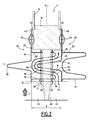
Figure 2 is an enlarged view of the nuclear fuel assembly lower end portion ofFigure 1 ; -
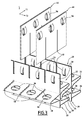
Figure 3 and4 are partial perspective views, respectively exploded and assembled, of the debris filter ofFigure 1 ; and -
Figure 5 - 8 are views similar to that ofFigures 1 - 4 , illustrating another embodiment of a debris filter. - The
nuclear fuel assembly 2 ofFigure 1 comprises a bundle offuel rods 4, adebris filter 6 for filtering debris contained in a coolant fluid supplied to the bundle offuel rods 4 and asupport plate 8 for supporting thefilter 6 and thefuel rods 4. - The
fuel rods 4 are elongated and extend parallel to each other in a longitudinal direction L. Thefuel rods 4 are arranged in a lattice (e.g. a 10x10 lattice) and spaced transversely to allow coolant fluid flow between them mainly in the longitudinal direction L. - In use, the
fuel assembly 2 is placed in a nuclear reactor core with the longitudinal direction L substantially vertical and a coolant fluid is supplied to flow mainly upwardly in the longitudinal direction L as illustrated by arrow F onFigure 1 . In the following, the terms relating to orientation refer to the position of thefuel assembly 2 as used in a nuclear reactor core. - Each
fuel rod 4 comprises atubular cladding 10 for receiving a stack of nuclear fuel pellets (not shown), abottom end cap 12 for closing the bottom end of thecladding 10 and alower pin 14 projecting downwardly from thebottom end cap 12 and of smaller diameter than thebottom end cap 12. Only the lower end portions of fourfuel rods 4 are visible onFigure 1 . - The
filter 6 is disposed at the bottom end of the bundle offuel rods 4 and extends transversely. It comprises alower face 16 and anupper face 18. - The
filter 6 compriseswalls 20 distributed in a first transverse direction T1 in spaced relationship with a constant pitch P (Figure 2 ), each pair ofadjacent walls 20 defining between them aduct 22 allowing coolant fluid to flow upwardly through thefilter 6. - The
walls 20 are elongated and extend parallel to each other in a second transverse direction T2 (Figure 3 ) perpendicular to the first transverse direction T1 (i.e. perpendicular to the plane ofFigure 1 ). - As illustrated on
Figure 2 , eachwall 20 is provided withdeflectors wall 20 transversely towards eachadjacent wall 20. - The
deflectors duct 22 from the pair of confrontingadjacent walls 20 defining theduct 22 intermesh with overlapping in the longitudinal direction L to define inside the duct 22 a zigzag shapedflow channel 30. - The expression "zigzag shaped" refers in the context of the invention in a general manner to a non-linear channel having successive sections inclined relative to the longitudinal direction L and extending alternately from one wall of the pair of walls towards the other wall (on the
Figure 2 from right to left and left to right). - The
deflectors duct 22 are alternated along the longitudinal direction L between one deflector of onewall 20 and one deflector of theother wall 20 of the pair of adjacent and confrontingwalls 20 defining theduct 22. - Each
intermediate wall 20 separating twoadjacent ducts 22 is provided with oneupper deflector 24 and onelower deflector 26 protruding on one face of thewall 20 with a longitudinal spacing between them, and oneintermediate deflector 28 protruding on the opposite face of thewall 20, at a level intermediate that of the upper andlower deflectors -
Walls 20 delimiting onesingle duct 22 comprise either onelower deflector 26 and oneupper deflector 24 or oneintermediate deflector 28, as illustrated on the right and left onFigure 1 .Such walls 20 are provided e.g. at the ends of thefilter 6 or adjacent openings for water channels in the case of a filter to be used in a BWR (Boiling Water Reactor) fuel assembly. - Back to
Figure 2 , the pitch P is set such that eachintermediate deflector 28 of onewall 20 is inserted between the upper andlower deflectors adjacent partition wall 20 with overlapping in the longitudinal direction L. - The
deflectors duct 22 are spaced longitudinally such that the width W of the channel 30 (defined as the distance between confronting faces of thedeflectors - Each
channel 30 comprises twoinclined sections channel 30 comprises a lowerinclined section 32 extending upwardly and laterally on a first side (on the left onFigure 2 ) from thelower face 16 and an upperinclined section 34 extending upwardly and laterally on the opposite side (on the right onFigure 2 ) from the lowerinclined section 32. - The lower
inclined section 32 of eachchannel 30 is defined between onelower deflector 26 and oneintermediate deflector 28 of one pair ofadjacent walls 20, and its upperinclined section 34 is defined between oneintermediate deflector 28 and oneupper deflector 24 of the pair ofadjacent walls 20. - In each
duct 22, theoverlapping deflectors holes 36 aligned in along a longitudinal axis A to define through the overlappingdeflectors passages 38 each for accommodating thepin 14 of arespective fuel rod 4. Each set of alignedholes 36 defines onepassage 38. -
Passages 38 are distributed in theducts 22 of thefilter 6 correspondingly to thefuel rods 4. Namely, sets of alignedholes 36 are distributed in the overlappingdeflectors duct 22 along the second transverse direction T2. - The diameter of the
holes 36 is adapted such that thepins 14 are received with a clearance in theholes 36 relative to the axis A of thepassage 38. An annular flow path is thus defined around eachpin 14. - Each
inclined section channel 30 intersects thepassages 38 extending through thedeflectors channel 30. Eachchannel 30 thus intersects twice thecorresponding passages 38. - Each
intermediate wall 20 separating twoadjacent ducts 22 is made up of twometallic sheets deflectors partition wall 20 being made up of folds of thesheets such wall 20 comprises ahollow cavity 44 delimited between the folds of the twosheets - Each
end wall 20 delimiting onesingle duct 22 is made up of one metallic sheet or two metallic sheets, one of them being provided with at least one deflector fold. - As illustrated on
Figures 3 and4 , thefilter 6 comprisesconnection strips 46 interlaced at 90° with thewalls 20 and conferring to the filter 6 a grid-shaped or latticed structure. - The
connection strips 46 and thewalls 20 are provided with confronting slots 48 (Figure 3 ) of their edges for interlocking thestrips 46 with thewalls 20. - The
walls 20 compriseupper portions 50 extending upwardly from thedeflectors upper portions 50 define with the connection strips 46 a lattice of square shaped cells 52 (Figure 4 ). Eachcell 52 is aligned with arespective passage 38 and adapted to receive thebottom end cap 12 of arespective fuel rod 4. - The
upper portion 50 of thewalls 20 and theconnection strips 46 are provided with springs respectively 54, 56 for transversely supporting thebottom end caps 12 received in thecells 52 and avoiding lift-off of thefuel rods 4. - The
springs cell 52 defined by thepartition walls 20 and theconnection strips 46. Onespring cell 52. - Preferably, each
cell 52 is provided with at least two springs in order to secure thefuel rods 4 against undesired vertical movements, partial length BWR fuel rods included. In an alternative embodiment, eachcell 52 is provided with one single annular spring assembled to thewalls 20 and/or connection strips 46. - As illustrated on
Figure 4 , the bottom end caps 12 of thefuel rods 4 are provided withannular grooves 57 and thesprings grooves 57. - Each
connection strip 46 extends downwardly to the lower edge of thewalls 20. The connection strips 46 thus subdivide eachchannel 30 between eachpassage 38. To allow insertions of the connection strips 46, thedeflectors wall 20 are provided with openings 58 (Figure 3 ) located between theholes 36. - As illustrated on
Figure 1 , thesupport plate 8 is disposed below thefilter 6. It is grid-shaped and comprisesbars 60 defining between themopenings 62. -
Bars 60 of thesupport plate 8 extend in register with thepassages 38 and thepins 14 extending through thepassages 38. Thebars 60 provide an axial abutment to thepins 14 of thefuel rods 4 and are designed to carry the load of thefuel rods 4, whereby thesupport plate 8 supports thefuel rods 4. - As illustrated on
Figure 2 , thepassages 38 and thechannels 30 are configured such that the coolant fluid supplied through theopenings 62 of thesupport plate 8 to thelower face 16 of thefilter 6 will flow into the channels 30 (arrow F1) and the annular flow paths defined inside thepassages 38 around the pins 14 (arrows F2). - Preferably, the dimensions are chosen such that the flow resistance of the
channels 30 and that of the annular flow paths are comparable, taking into account the zigzag shape of thechannels 30, the width W of thechannels 30, the partial obstruction provided by thepins 14 into thechannels 30 depending on the diameter of thepins 14, and the clearance between theholes 36 and thepins 14. - In one example, the pin diameter is of approximately 3.5 mm, the diameter of the
holes 36 is approximately of 6.5 mm, the radial clearance of approximately 1.5 mm, the width W of thechannels 30 is of approximately 2.8 mm, and the pitch P is of approximately 12.65 mm. - In use, the coolant fluid is supplied to the
lower face 16 of thefilter 6 and flows mainly upwardly in the longitudinal direction L, as illustrated by arrow F onFigure 1 . The coolant fluid flows in eachduct 22 by entering the channel 30 (arrow F1) and the annular flow paths (arrow F2) defined in eachpassage 38 around thepins 14. - The baffled shape of the
channels 30 allows catching debris. - The stream flowing through each annular flow path interferes with the stream flowing through the corresponding
channel 30. This avoids imparting any preferred orientation to the debris inside thechannel 30 and allows enhanced debris retention. - The
pins 14 extending in eachchannel 30 form obstacles perturbing fluid flow in thechannel 30 and avoiding clear orientation of the debris. - The
fuel rods 4 are secured against lateral shuddering and longitudinal lift-off by thesprings cell 52 defined by theupper portions 50 of thepartition walls 20 and the connection strips 46 above thechannels 30. - The anti lift-off function is enhanced by the
groove 57 for receiving thesprings fuel rods 4 when assembling thefuel assembly 2. - The
pins 14 of thefuel rods 4 accommodated in thepassages 38 provided in thefilter 6 also contribute to securing the fuel rods against lateral shuddering and longitudinal lift-off. - The
cavities 44 defined between the foldeddeflectors sheets - The connection strips 46 subdividing each
channel 30 enhance trapping elongated debris oriented in the second transverse direction T2. - The filtering function and the supporting function are operated by the same structure (filter 6) having reduced height. The height of the
pin 14 may typically be of approximately 15 mm. - Since the
debris filter 6 also fixes thefuel rods 4, it is possible to suppress the conventional first spacer grid located at a distance above the lowerend debris filter 6, thus saving costs. - The
filter 6 arranged on top of thesupport plate 8 and adapted to receive the lower end portion of thefuel rods 4 allows providingfuel rods 4 with additional length which could serve as fission gas plenum and/or for increasing the total amount of fissile material of theassembly 2. - Each
wall 20 is obtained by providing initiallyflat sheets holes 36, subsequently folding thesheets deflectors sheets sheets sheets - The embodiment illustrated on
Figure 5 differs from that ofFigures 1 - 4 namely by the structure of the walls delimiting the ducts and the deflectors. - In this embodiment, each
wall 20 extends parallel to the longitudinal direction L and is provided with twodeflector plates 72 interlaced at an angle relative to thewall 20 such that eachdeflector plate 72 defines two deflectors 74 (Figure 6 ) protruding on each side of thewall 20. The twodeflector plates 72 are parallel and spaced longitudinally. - As illustrated on
Figure 6 , thedeflector plates 72 intersect thewalls 20 at an angle inferior to 90° such that eachdeflector plate 72 defines onedeflector 74 extending upwardly on one side of the wall 20 (on the right onFigure 6 ) and onedeflector 74 extending downwardly on the opposite side of the wall 20 (on the left onFigure 6 ). - In each
duct 22, downwardly extendingdeflectors 74 provided on onewall 20 of the pair ofadjacent walls 20 delimiting theduct 22 intermeshes and overlaps in the longitudinal direction L with the upwardly extendingdeflectors 74 provided on theother wall 20 of the pair ofadjacent walls 20. - Each
channel 30 defined between twoadjacent walls 20 is thus zigzag shaped and comprises three inclined sections including one intermediate section extending downwardly. - The
deflectors 74 are provided with sets ofholes 76 aligned along longitudinal axis A to definepassages 38 for receiving thepins 14. - As illustrated on
Figure 7 , thefilter 6 of the second embodiment has connection strips 46 of smaller height than thewalls 20. They are interlocked on the upper edges of thewalls 20 and end before thedeflectors 74. - The
upper portions 50 of thewalls 20 and the connection strips 46 are provided withsprings cells 52 defined between them and preventing lift-off of thefuel rods 4. For providingsprings walls 20 or on the connection strips 46, there are formed e.g. of two sheets. - The
walls 20 and thedeflector plates 72 are provided with confronting interlockingslots 78 extending on half their length in the second transverse direction T2. - Each
deflector plate 72 is provided with two parallel series ofholes 76, each one extending in a lateral portion of thedeflector plate 72 defining adeflector 74, i.e. on each side of the interlockingslot 78. - The length of the
walls 20,plates 72, interlockingslots 78 and the number ofholes 76 are limited onFigure 7 for the sake of clarity and correspond in practice to the number offuel rods 4 in the lattice. - The
filter 6 further comprises additional connection strips 80 interlocked on the lower edges of thewalls 20 via confronting interlockingslots 82 provided on the lower edges of thewalls 20 and the upper edges of the additional connection strips 80. - The
filter 6 ofFigures 5 - 8 offers the same advantages as that ofFigures 1 - 4 with respect to debris catching, except that thewalls 20 are deprived of internal cavities. - The
filter 6 ofFigures 5 - 8 is obtainable simply, at low cost and with good reproducibility from essentially flat metallic sheets. - The sections of the channels of the embodiments of
Figures 1 - 4 and5 - 8 are inclined at an angle inferior or superior to 90° relative to the longitudinal direction L. Alternately, at least one section or each section of a channel is at an angle of 90° relative to the longitudinal direction L. This may be obtained in a variant of the filter ofFigures 5 - 8 by providing deflectors on the walls of each pair of adjacent walls arranged at an angle of 90° relative to the longitudinal direction L and offset in the longitudinal direction L. - The number of sections of the channels of the embodiments of
Figures 1 - 4 andFigures 5 - 8 is not limited to two or three. Alternately or in option, at least one or each channel has a different number of sections, namely two sections, three sections or more than four sections. - In the embodiments of
Figures 1 - 4 andFigures 5 - 8 , thewalls 20 extend upwardly from thedeflectors cells 52 for accommodating the bottom end caps 12 and providingsprings - In a variant, the partition walls are deprived of such springs and in such case, the upper portions of the partition walls can be made shorter above the deflector for limiting the height of the trap while allowing interlocking with connection strips.
- In the embodiments of
Figures 1 - 4 and5 - 8 , the filter is disposed on top of the support plate and the fuel rods extend through the filter and abut onto bars of the support plate. The filter may be disposed below the support plate. In such case, holes for defining passages for accommodating the lower end portions of the fuel rods and/or the upper portions of the walls extending above the deflectors may be omitted. Besides, bars of the support plate are arranged to support the lower end portions of the fuel rods and openings of the support plate are arranged to allow coolant to flow out from the channels of the filter. In option, an additional spacer grid corresponding to the upper portions of the walls may be added on top of the support plate for providing lateral support to the lower end portions of the fuel rods. - Filters such as that of
Figures 1 - 4 and5 - 8 but deprived of passages for the fuel rods and/or springs for lateral support of the fuel rods still have the advantage of a simple and low cost construction. - The filters of
Figures 1 - 4 and5 - 8 are described for the sake of clarity for a lattice of fuel rods. - In a known manner, a Pressurized Water Reactor (PWR) fuel assembly comprises guide tubes for accommodating cluster rods and may comprise an instrumentation tube for accommodating the core instrumentation. Such tubes replacing some of the fuel rods in the lattice do not comprise fissile material and the filter is adapted to provide specific positions for receiving the tubes.
- A fuel assembly for a BWR conventionally comprises at least one water channel replacing one or several fuel rods in the lattice of fuel rods and the filter is adapted for allowing passage of such water channel through the filter as in spacer grids distributed along the fuel rods.
- The filter of the invention is usable for fuel assembly of various types, such as fuel assemblies for use in BWR (Boiling Water Reactor) or PWR (Pressurized Water Reactor).
Claims (12)
- Debris filter (6) for use in a nuclear fuel assembly (2) comprising a bundle of fuel rods (4) to be supplied with a coolant fluid flow, of the type comprising a plurality of flow ducts (22) extending in a longitudinal direction (L) and each delimited between a pair of walls (20),
wherein the filter (6) comprises deflectors (24, 26, 28; 74) protruding into each duct (22) alternately from the pair of walls (20) with overlapping in the longitudinal direction (L) to define a zigzag shaped flow channel (30) and provided with at least one set of holes (36) aligned in the longitudinal direction (L) to define through the overlapping deflectors (24, 26, 28; 74) a passage (38) for accommodating a lower end pin (14) of a fuel rod (4). - Debris filter according to claim 1, comprising in each duct (22) in register in the longitudinal direction (L) with each passage (38) one cell (52) for accommodating a bottom end cap (12) of a fuel rod (4).
- Debris filter according to claim 2, comprising at least one spring (54, 56) provided in each cell (52) for transversely and/or longitudinally supporting a bottom end cap (12) accommodated in the cell (52).
- Debris filter according to any one of the preceding claims, comprising walls (20) each made up of at least one metallic sheet (40, 42) provided with at least one deflector fold for forming one deflector (24, 26, 28).
- Debris filter according to claim 4, comprising intermediate walls (20) separating two adjacent ducts (22) and each made up of two metallic sheets (40, 42) provided with deflector folds protruding on opposite faces of the wall (20).
- Debris filter according to claim 5, wherein each intermediate walls (20) is provided with one deflector fold protruding from one of the opposed faces of the wall (20) at a level intermediate two deflector folds protruding from the other one of the opposed faces of the wall (20).
- Debris filter according to any one of the preceding claims, comprising deflectors (74) formed by plates (72) secured to the walls (20) at an angle.
- Debris filter according to claim 7, comprising intermediate walls (20) separating two adjacent ducts (22) each provided with at least one deflector plate (72) interlocked with the intermediate wall (20) to form two deflectors (74) each protruding on a respective face of the wall (20).
- Debris filter according to claim 8, comprising at least one pair of adjacent intermediate walls (20) provided with deflector plates (72) intersecting the corresponding intermediate walls (20) at the same level.
- Debris filter according to any one of the preceding claims, comprising connection strips (46, 80) interlocked perpendicularly with the walls (20).
- Nuclear fuel assembly (2) comprising a bundle of fuel rods (4) extending in a longitudinal direction (L) and each comprising a pin (14) at a lower end and a debris filter (6) as any one of the preceding claims 1 to 10, the pin (14) of each fuel rod (4) being accommodated in one passage (38).
- Nuclear fuel assembly (2) according to claim 11, comprising a grid-shaped support plate (8) disposed below the debris filter (6), said support plate (8) comprising bars (60) defining between them openings (62), bars (60) being arranged for supporting the fuel rods (4) extending through the passages (38) and openings (62) being arranged to allow coolant flow though the support plate (8) into the channels (30) of the filter (6).
Priority Applications (4)
| Application Number | Priority Date | Filing Date | Title |
|---|---|---|---|
| EP08306029.3A EP2204819B1 (en) | 2008-12-31 | 2008-12-31 | Debris filter for use in a nuclear fuel assembly |
| ES08306029.3T ES2490818T3 (en) | 2008-12-31 | 2008-12-31 | Waste filter for use in a nuclear fuel assembly |
| US13/143,015 US8824621B2 (en) | 2008-12-31 | 2009-12-29 | Debris filter for use in a nuclear fuel assembly |
| PCT/EP2009/067980 WO2010076315A2 (en) | 2008-12-31 | 2009-12-29 | Debris filter for use in a nuclear fuel assembly |
Applications Claiming Priority (1)
| Application Number | Priority Date | Filing Date | Title |
|---|---|---|---|
| EP08306029.3A EP2204819B1 (en) | 2008-12-31 | 2008-12-31 | Debris filter for use in a nuclear fuel assembly |
Publications (2)
| Publication Number | Publication Date |
|---|---|
| EP2204819A1 true EP2204819A1 (en) | 2010-07-07 |
| EP2204819B1 EP2204819B1 (en) | 2014-06-04 |
Family
ID=41351561
Family Applications (1)
| Application Number | Title | Priority Date | Filing Date |
|---|---|---|---|
| EP08306029.3A Not-in-force EP2204819B1 (en) | 2008-12-31 | 2008-12-31 | Debris filter for use in a nuclear fuel assembly |
Country Status (4)
| Country | Link |
|---|---|
| US (1) | US8824621B2 (en) |
| EP (1) | EP2204819B1 (en) |
| ES (1) | ES2490818T3 (en) |
| WO (1) | WO2010076315A2 (en) |
Cited By (4)
| Publication number | Priority date | Publication date | Assignee | Title |
|---|---|---|---|---|
| EP2525362A1 (en) * | 2011-05-20 | 2012-11-21 | Areva NP | Debris filter for nuclear reactor installation and nucluar fuel assembly comprising such a debris filter |
| CN103337262A (en) * | 2013-06-18 | 2013-10-02 | 中国核动力研究设计院 | A kind of bottom nozzle with filtration foreign matter function |
| WO2021064171A1 (en) | 2019-10-04 | 2021-04-08 | Framatome | Nuclear fuel assembly bottom end part debris filter and method of manufacturing such a debris filter |
| WO2021064170A1 (en) | 2019-10-04 | 2021-04-08 | Framatome | Debris filter for a nuclear fuel assembly bottom end part and method of manufacturing such a debris filter |
Families Citing this family (6)
| Publication number | Priority date | Publication date | Assignee | Title |
|---|---|---|---|---|
| US9767927B2 (en) | 2011-12-12 | 2017-09-19 | Dominion Engineering, Inc. | Particulate removal system |
| EP3596735B1 (en) * | 2017-03-17 | 2024-01-24 | Westinghouse Electric Company Llc | Nuclear fuel assembly debris filtering bottom nozzle |
| US10923237B2 (en) * | 2017-08-28 | 2021-02-16 | Global Nuclear Fuel—Americas, LLC | Debris filters for nuclear fuel assembly and method of using the same |
| AR113747A1 (en) * | 2017-10-06 | 2020-06-10 | Candu Energy Inc | METHOD AND APPARATUS FOR FILTERING FLUIDS IN NUCLEAR ENERGY GENERATION |
| SI3709310T1 (en) * | 2019-03-12 | 2022-01-31 | Westinghouse Electric Sweden Ab | A filter and a fuel assembly for a nuclear plant |
| CN113362976A (en) * | 2021-06-04 | 2021-09-07 | 中国核动力研究设计院 | Efficient filtering lower pipe seat, fuel assembly and nuclear reactor |
Citations (3)
| Publication number | Priority date | Publication date | Assignee | Title |
|---|---|---|---|---|
| US5030412A (en) * | 1990-05-04 | 1991-07-09 | Advanced Nuclear Fuels Corporation | Fuel assembly debris screen |
| DE19504612A1 (en) * | 1994-02-15 | 1995-08-17 | Gen Electric | Large surface area sieve plate for a boiling water nuclear reactor |
| DE29615575U1 (en) * | 1996-09-06 | 1997-01-16 | Siemens AG, 80333 München | Fuel element with debris filter |
Family Cites Families (29)
| Publication number | Priority date | Publication date | Assignee | Title |
|---|---|---|---|---|
| US3439650A (en) * | 1965-07-12 | 1969-04-22 | Borg Warner | Information transfer and ink particle refining system |
| US3820226A (en) * | 1970-06-01 | 1974-06-28 | Continental Oil Co | Method of assembling nuclear reactor fuel element spacer assembly |
| US3746617A (en) * | 1970-06-01 | 1973-07-17 | Continental Oil Co | Nuclear reactor fuel element spacer assembly |
| US3820225A (en) * | 1970-06-01 | 1974-06-28 | Continental Oil Co | Method of assembling nuclear reactor fuel element spacer assembly |
| US3814666A (en) * | 1971-01-04 | 1974-06-04 | Combustion Eng | Staggered cone deflectors |
| US3809609A (en) * | 1972-06-27 | 1974-05-07 | Combustion Eng | Twisted tape flow deflector in a nuclear reactor fuel assembly |
| DE2364928A1 (en) | 1973-12-28 | 1975-07-03 | Wilfried Picard | Crane lifting spreader - allows load to be tilted to desired angle |
| US4039379A (en) * | 1975-02-28 | 1977-08-02 | Exxon Nuclear Company, Inc. | Mixing vane grid spacer |
| US4165256A (en) * | 1975-03-03 | 1979-08-21 | The Babcock & Wilcox Company | Fuel element grid plate with corrugation and bosses |
| US4135972A (en) * | 1976-03-29 | 1979-01-23 | Combustion Engineering, Inc. | Nuclear reactor spacer assembly |
| US4077843A (en) * | 1976-05-21 | 1978-03-07 | Exxon Nuclear Company, Inc. | Nuclear reactor spring strip grid spacer |
| US4125435A (en) * | 1977-02-25 | 1978-11-14 | The Babcock & Wilcox Company | Grid lattice with sliding strap |
| US4692302A (en) * | 1983-12-30 | 1987-09-08 | Westinghouse Electric Corp. | Coolant flow mixer grid for a nuclear reactor fuel assembly |
| FR2572837B1 (en) * | 1984-11-05 | 1989-05-05 | Fragema Framatome & Cogema | GRILLE WITH MIXED FINS FOR NUCLEAR FUEL ASSEMBLY |
| US4684495A (en) * | 1984-11-16 | 1987-08-04 | Westinghouse Electric Corp. | Fuel assembly bottom nozzle with integral debris trap |
| US4684496A (en) * | 1984-11-16 | 1987-08-04 | Westinghouse Electric Corp. | Debris trap for a pressurized water nuclear reactor |
| US4654194A (en) * | 1985-09-09 | 1987-03-31 | The United States Of America As Represented By The United States Department Of Energy | Inlet nozzle assembly |
| US4844860A (en) * | 1986-06-20 | 1989-07-04 | Combustion Engineering, Inc. | Support grid with integral vanes |
| FR2603497B1 (en) * | 1986-09-10 | 1991-10-04 | Commissariat Energie Atomique | COLD LIQUID METAL PURIFICATION TRAP CONTAINING DISSOLVED IMPURITIES |
| US4775510A (en) * | 1986-12-22 | 1988-10-04 | Combustion Engineering, Inc. | Nuclear fuel assembly hollow flow deflector |
| US4781884A (en) * | 1987-03-02 | 1988-11-01 | Combustion Engineering, Inc. | Debris catching strainer grid |
| US4913875A (en) * | 1987-09-24 | 1990-04-03 | General Electric Company | Swirl vanes integral with spacer grid |
| US5390220A (en) * | 1993-11-29 | 1995-02-14 | General Electric Company | Lower tie plate strainers including helical spring strainers for boiling water reactors |
| US5345483A (en) * | 1993-12-02 | 1994-09-06 | General Electric Company | Lower tie plate strainers having double plate with offset holes for boiling water reactors |
| US5479461A (en) * | 1994-06-30 | 1995-12-26 | Siemens Power Corporation | Attachable debris filter for BWR nuclear fuel assemblies |
| US5528640A (en) * | 1994-11-07 | 1996-06-18 | General Electric Company | Low pressure double offset plate catcher for a nuclear reactor |
| JP3044338B2 (en) * | 1996-09-13 | 2000-05-22 | 原子燃料工業株式会社 | PWR fuel assembly |
| SE521610C2 (en) * | 2001-01-22 | 2003-11-18 | Westinghouse Atom Ab | Filters and fuel cartridge for a light-water nuclear plant |
| US8317035B2 (en) * | 2004-12-30 | 2012-11-27 | Global Nuclear Fuel-Americas, Llc. | Debris filter |
-
2008
- 2008-12-31 EP EP08306029.3A patent/EP2204819B1/en not_active Not-in-force
- 2008-12-31 ES ES08306029.3T patent/ES2490818T3/en active Active
-
2009
- 2009-12-29 WO PCT/EP2009/067980 patent/WO2010076315A2/en not_active Ceased
- 2009-12-29 US US13/143,015 patent/US8824621B2/en not_active Expired - Fee Related
Patent Citations (4)
| Publication number | Priority date | Publication date | Assignee | Title |
|---|---|---|---|---|
| US5030412A (en) * | 1990-05-04 | 1991-07-09 | Advanced Nuclear Fuels Corporation | Fuel assembly debris screen |
| EP0455010A1 (en) | 1990-05-04 | 1991-11-06 | Siemens Aktiengesellschaft | Fuel assembly debris screen |
| DE19504612A1 (en) * | 1994-02-15 | 1995-08-17 | Gen Electric | Large surface area sieve plate for a boiling water nuclear reactor |
| DE29615575U1 (en) * | 1996-09-06 | 1997-01-16 | Siemens AG, 80333 München | Fuel element with debris filter |
Cited By (14)
| Publication number | Priority date | Publication date | Assignee | Title |
|---|---|---|---|---|
| US9583222B2 (en) | 2011-05-20 | 2017-02-28 | Areva Np | Debris filter for nuclear reactor installation and nuclear fuel assembly comprising such a debris filter |
| WO2012160000A1 (en) * | 2011-05-20 | 2012-11-29 | Areva Np | Debris filter for nuclear reactor installation and nuclear fuel assembly comprising such a debris filter |
| EP2525362A1 (en) * | 2011-05-20 | 2012-11-21 | Areva NP | Debris filter for nuclear reactor installation and nucluar fuel assembly comprising such a debris filter |
| CN103548088A (en) * | 2011-05-20 | 2014-01-29 | 阿海珐核能公司 | Debris filter for nuclear reactor installation and nuclear fuel assembly comprising such a debris filter |
| US20140056397A1 (en) * | 2011-05-20 | 2014-02-27 | Areva Np | Debris filter for nuclear reactor installation and nuclear fuel assembly comprising such a debris filter |
| KR20140031306A (en) * | 2011-05-20 | 2014-03-12 | 아레바 엔피 | Debris filter for nuclear reactor installation and nuclear fuel assembly comprising such a debris filter |
| CN103548088B (en) * | 2011-05-20 | 2016-08-17 | 阿海珐核能公司 | Debris filter and the nuclear fuel assembly including this debris filter for nuclear reactor facility |
| GB2524455B (en) * | 2013-06-18 | 2020-04-15 | Nuclear Power Inst China | Lower tube socket with foreign matter filtering function |
| CN103337262A (en) * | 2013-06-18 | 2013-10-02 | 中国核动力研究设计院 | A kind of bottom nozzle with filtration foreign matter function |
| WO2014201818A1 (en) * | 2013-06-18 | 2014-12-24 | 中国核动力研究设计院 | Lower tube socket with foreign matter filtering function |
| GB2524455A (en) * | 2013-06-18 | 2015-09-23 | Nuclear Power Inst China | Lower tube socket with foreign matter filtering function |
| WO2021064170A1 (en) | 2019-10-04 | 2021-04-08 | Framatome | Debris filter for a nuclear fuel assembly bottom end part and method of manufacturing such a debris filter |
| WO2021064171A1 (en) | 2019-10-04 | 2021-04-08 | Framatome | Nuclear fuel assembly bottom end part debris filter and method of manufacturing such a debris filter |
| US12412673B2 (en) | 2019-10-04 | 2025-09-09 | Framatome | Debris filter for a nuclear fuel assembly bottom end part and method of manufacturing such a debris filter |
Also Published As
| Publication number | Publication date |
|---|---|
| WO2010076315A2 (en) | 2010-07-08 |
| US8824621B2 (en) | 2014-09-02 |
| US20110268240A1 (en) | 2011-11-03 |
| EP2204819B1 (en) | 2014-06-04 |
| ES2490818T3 (en) | 2014-09-04 |
| WO2010076315A3 (en) | 2010-08-26 |
Similar Documents
| Publication | Publication Date | Title |
|---|---|---|
| EP2204819B1 (en) | Debris filter for use in a nuclear fuel assembly | |
| EP2031599B1 (en) | Debris shield for upper tie plate in a nuclear fuel bundle and method for filtering debris | |
| US9583222B2 (en) | Debris filter for nuclear reactor installation and nuclear fuel assembly comprising such a debris filter | |
| US4775509A (en) | Spacer grid for a nuclear fuel assembly | |
| EP0906628B1 (en) | Nuclear fuel assembly | |
| KR910001978B1 (en) | Support grid with integral vanes | |
| CN1860554B (en) | Nuclear Fuel Assemblies Containing Internal Stiffeners | |
| EP2710602B1 (en) | Nuclear fuel assembly tie plate, upper nozzle and nuclear fuel assembly comprising such a tie plate | |
| ES2992519T3 (en) | Nuclear fuel assembly bottom debris filter and manufacturing process for such debris filter | |
| US4134791A (en) | Plate-type fuel assembly for a nuclear reactor | |
| TW201312590A (en) | Nuclear fuel assembly tie plate, upper nozzle and nuclear fuel assembly comprising such a tie plate | |
| KR102939021B1 (en) | Nuclear fuel assembly with reinforcement device | |
| ES2992486T3 (en) | Nuclear fuel assembly and method of manufacturing said nuclear fuel assembly | |
| JP2005172748A (en) | Foreign matter filter for reactor and fuel assembly | |
| EP0846327B1 (en) | Spacer for a fuel assembly and a fuel assembly | |
| KR100981669B1 (en) | Support grid with insert curved spring plate | |
| KR101062786B1 (en) | Support grid of nuclear fuel rods |
Legal Events
| Date | Code | Title | Description |
|---|---|---|---|
| PUAI | Public reference made under article 153(3) epc to a published international application that has entered the european phase |
Free format text: ORIGINAL CODE: 0009012 |
|
| AK | Designated contracting states |
Kind code of ref document: A1 Designated state(s): AT BE BG CH CY CZ DE DK EE ES FI FR GB GR HR HU IE IS IT LI LT LU LV MC MT NL NO PL PT RO SE SI SK TR |
|
| AX | Request for extension of the european patent |
Extension state: AL BA MK RS |
|
| 17P | Request for examination filed |
Effective date: 20101124 |
|
| 17Q | First examination report despatched |
Effective date: 20110119 |
|
| AKX | Designation fees paid |
Designated state(s): AT BE BG CH CY CZ DE DK EE ES FI FR GB GR HR HU IE IS IT LI LT LU LV MC MT NL NO PL PT RO SE SI SK TR |
|
| GRAP | Despatch of communication of intention to grant a patent |
Free format text: ORIGINAL CODE: EPIDOSNIGR1 |
|
| INTG | Intention to grant announced |
Effective date: 20131022 |
|
| GRAS | Grant fee paid |
Free format text: ORIGINAL CODE: EPIDOSNIGR3 |
|
| GRAA | (expected) grant |
Free format text: ORIGINAL CODE: 0009210 |
|
| RAP1 | Party data changed (applicant data changed or rights of an application transferred) |
Owner name: AREVA NP |
|
| AK | Designated contracting states |
Kind code of ref document: B1 Designated state(s): AT BE BG CH CY CZ DE DK EE ES FI FR GB GR HR HU IE IS IT LI LT LU LV MC MT NL NO PL PT RO SE SI SK TR |
|
| REG | Reference to a national code |
Ref country code: GB Ref legal event code: FG4D |
|
| REG | Reference to a national code |
Ref country code: CH Ref legal event code: EP |
|
| REG | Reference to a national code |
Ref country code: AT Ref legal event code: REF Ref document number: 671471 Country of ref document: AT Kind code of ref document: T Effective date: 20140615 |
|
| REG | Reference to a national code |
Ref country code: IE Ref legal event code: FG4D |
|
| REG | Reference to a national code |
Ref country code: DE Ref legal event code: R096 Ref document number: 602008032548 Country of ref document: DE Effective date: 20140717 |
|
| REG | Reference to a national code |
Ref country code: SE Ref legal event code: TRGR |
|
| REG | Reference to a national code |
Ref country code: ES Ref legal event code: FG2A Ref document number: 2490818 Country of ref document: ES Kind code of ref document: T3 Effective date: 20140904 |
|
| REG | Reference to a national code |
Ref country code: AT Ref legal event code: MK05 Ref document number: 671471 Country of ref document: AT Kind code of ref document: T Effective date: 20140604 |
|
| REG | Reference to a national code |
Ref country code: NL Ref legal event code: VDEP Effective date: 20140604 |
|
| PG25 | Lapsed in a contracting state [announced via postgrant information from national office to epo] |
Ref country code: GR Free format text: LAPSE BECAUSE OF FAILURE TO SUBMIT A TRANSLATION OF THE DESCRIPTION OR TO PAY THE FEE WITHIN THE PRESCRIBED TIME-LIMIT Effective date: 20140905 Ref country code: NO Free format text: LAPSE BECAUSE OF FAILURE TO SUBMIT A TRANSLATION OF THE DESCRIPTION OR TO PAY THE FEE WITHIN THE PRESCRIBED TIME-LIMIT Effective date: 20140904 Ref country code: FI Free format text: LAPSE BECAUSE OF FAILURE TO SUBMIT A TRANSLATION OF THE DESCRIPTION OR TO PAY THE FEE WITHIN THE PRESCRIBED TIME-LIMIT Effective date: 20140604 Ref country code: LT Free format text: LAPSE BECAUSE OF FAILURE TO SUBMIT A TRANSLATION OF THE DESCRIPTION OR TO PAY THE FEE WITHIN THE PRESCRIBED TIME-LIMIT Effective date: 20140604 Ref country code: CY Free format text: LAPSE BECAUSE OF FAILURE TO SUBMIT A TRANSLATION OF THE DESCRIPTION OR TO PAY THE FEE WITHIN THE PRESCRIBED TIME-LIMIT Effective date: 20140604 |
|
| REG | Reference to a national code |
Ref country code: LT Ref legal event code: MG4D |
|
| PG25 | Lapsed in a contracting state [announced via postgrant information from national office to epo] |
Ref country code: LV Free format text: LAPSE BECAUSE OF FAILURE TO SUBMIT A TRANSLATION OF THE DESCRIPTION OR TO PAY THE FEE WITHIN THE PRESCRIBED TIME-LIMIT Effective date: 20140604 Ref country code: HR Free format text: LAPSE BECAUSE OF FAILURE TO SUBMIT A TRANSLATION OF THE DESCRIPTION OR TO PAY THE FEE WITHIN THE PRESCRIBED TIME-LIMIT Effective date: 20140604 Ref country code: AT Free format text: LAPSE BECAUSE OF FAILURE TO SUBMIT A TRANSLATION OF THE DESCRIPTION OR TO PAY THE FEE WITHIN THE PRESCRIBED TIME-LIMIT Effective date: 20140604 |
|
| PG25 | Lapsed in a contracting state [announced via postgrant information from national office to epo] |
Ref country code: CZ Free format text: LAPSE BECAUSE OF FAILURE TO SUBMIT A TRANSLATION OF THE DESCRIPTION OR TO PAY THE FEE WITHIN THE PRESCRIBED TIME-LIMIT Effective date: 20140604 Ref country code: EE Free format text: LAPSE BECAUSE OF FAILURE TO SUBMIT A TRANSLATION OF THE DESCRIPTION OR TO PAY THE FEE WITHIN THE PRESCRIBED TIME-LIMIT Effective date: 20140604 Ref country code: PT Free format text: LAPSE BECAUSE OF FAILURE TO SUBMIT A TRANSLATION OF THE DESCRIPTION OR TO PAY THE FEE WITHIN THE PRESCRIBED TIME-LIMIT Effective date: 20141006 Ref country code: RO Free format text: LAPSE BECAUSE OF FAILURE TO SUBMIT A TRANSLATION OF THE DESCRIPTION OR TO PAY THE FEE WITHIN THE PRESCRIBED TIME-LIMIT Effective date: 20140604 Ref country code: SK Free format text: LAPSE BECAUSE OF FAILURE TO SUBMIT A TRANSLATION OF THE DESCRIPTION OR TO PAY THE FEE WITHIN THE PRESCRIBED TIME-LIMIT Effective date: 20140604 |
|
| PG25 | Lapsed in a contracting state [announced via postgrant information from national office to epo] |
Ref country code: IS Free format text: LAPSE BECAUSE OF FAILURE TO SUBMIT A TRANSLATION OF THE DESCRIPTION OR TO PAY THE FEE WITHIN THE PRESCRIBED TIME-LIMIT Effective date: 20141004 Ref country code: NL Free format text: LAPSE BECAUSE OF FAILURE TO SUBMIT A TRANSLATION OF THE DESCRIPTION OR TO PAY THE FEE WITHIN THE PRESCRIBED TIME-LIMIT Effective date: 20140604 Ref country code: PL Free format text: LAPSE BECAUSE OF FAILURE TO SUBMIT A TRANSLATION OF THE DESCRIPTION OR TO PAY THE FEE WITHIN THE PRESCRIBED TIME-LIMIT Effective date: 20140604 |
|
| REG | Reference to a national code |
Ref country code: DE Ref legal event code: R097 Ref document number: 602008032548 Country of ref document: DE |
|
| PLBE | No opposition filed within time limit |
Free format text: ORIGINAL CODE: 0009261 |
|
| STAA | Information on the status of an ep patent application or granted ep patent |
Free format text: STATUS: NO OPPOSITION FILED WITHIN TIME LIMIT |
|
| PG25 | Lapsed in a contracting state [announced via postgrant information from national office to epo] |
Ref country code: IT Free format text: LAPSE BECAUSE OF FAILURE TO SUBMIT A TRANSLATION OF THE DESCRIPTION OR TO PAY THE FEE WITHIN THE PRESCRIBED TIME-LIMIT Effective date: 20140604 Ref country code: DK Free format text: LAPSE BECAUSE OF FAILURE TO SUBMIT A TRANSLATION OF THE DESCRIPTION OR TO PAY THE FEE WITHIN THE PRESCRIBED TIME-LIMIT Effective date: 20140604 |
|
| 26N | No opposition filed |
Effective date: 20150305 |
|
| REG | Reference to a national code |
Ref country code: DE Ref legal event code: R097 Ref document number: 602008032548 Country of ref document: DE Effective date: 20150305 |
|
| PG25 | Lapsed in a contracting state [announced via postgrant information from national office to epo] |
Ref country code: BE Free format text: LAPSE BECAUSE OF FAILURE TO SUBMIT A TRANSLATION OF THE DESCRIPTION OR TO PAY THE FEE WITHIN THE PRESCRIBED TIME-LIMIT Effective date: 20140604 |
|
| REG | Reference to a national code |
Ref country code: DE Ref legal event code: R119 Ref document number: 602008032548 Country of ref document: DE |
|
| PG25 | Lapsed in a contracting state [announced via postgrant information from national office to epo] |
Ref country code: SI Free format text: LAPSE BECAUSE OF FAILURE TO SUBMIT A TRANSLATION OF THE DESCRIPTION OR TO PAY THE FEE WITHIN THE PRESCRIBED TIME-LIMIT Effective date: 20140604 Ref country code: LU Free format text: LAPSE BECAUSE OF FAILURE TO SUBMIT A TRANSLATION OF THE DESCRIPTION OR TO PAY THE FEE WITHIN THE PRESCRIBED TIME-LIMIT Effective date: 20141231 |
|
| REG | Reference to a national code |
Ref country code: CH Ref legal event code: PL |
|
| REG | Reference to a national code |
Ref country code: IE Ref legal event code: MM4A |
|
| REG | Reference to a national code |
Ref country code: FR Ref legal event code: ST Effective date: 20150831 |
|
| PG25 | Lapsed in a contracting state [announced via postgrant information from national office to epo] |
Ref country code: LI Free format text: LAPSE BECAUSE OF NON-PAYMENT OF DUE FEES Effective date: 20141231 Ref country code: DE Free format text: LAPSE BECAUSE OF NON-PAYMENT OF DUE FEES Effective date: 20150701 Ref country code: IE Free format text: LAPSE BECAUSE OF NON-PAYMENT OF DUE FEES Effective date: 20141231 Ref country code: CH Free format text: LAPSE BECAUSE OF NON-PAYMENT OF DUE FEES Effective date: 20141231 |
|
| PG25 | Lapsed in a contracting state [announced via postgrant information from national office to epo] |
Ref country code: FR Free format text: LAPSE BECAUSE OF NON-PAYMENT OF DUE FEES Effective date: 20141231 |
|
| PG25 | Lapsed in a contracting state [announced via postgrant information from national office to epo] |
Ref country code: BG Free format text: LAPSE BECAUSE OF FAILURE TO SUBMIT A TRANSLATION OF THE DESCRIPTION OR TO PAY THE FEE WITHIN THE PRESCRIBED TIME-LIMIT Effective date: 20140604 Ref country code: MC Free format text: LAPSE BECAUSE OF FAILURE TO SUBMIT A TRANSLATION OF THE DESCRIPTION OR TO PAY THE FEE WITHIN THE PRESCRIBED TIME-LIMIT Effective date: 20140604 |
|
| PG25 | Lapsed in a contracting state [announced via postgrant information from national office to epo] |
Ref country code: MT Free format text: LAPSE BECAUSE OF FAILURE TO SUBMIT A TRANSLATION OF THE DESCRIPTION OR TO PAY THE FEE WITHIN THE PRESCRIBED TIME-LIMIT Effective date: 20140604 Ref country code: HU Free format text: LAPSE BECAUSE OF FAILURE TO SUBMIT A TRANSLATION OF THE DESCRIPTION OR TO PAY THE FEE WITHIN THE PRESCRIBED TIME-LIMIT; INVALID AB INITIO Effective date: 20081231 Ref country code: TR Free format text: LAPSE BECAUSE OF FAILURE TO SUBMIT A TRANSLATION OF THE DESCRIPTION OR TO PAY THE FEE WITHIN THE PRESCRIBED TIME-LIMIT Effective date: 20140604 |
|
| PGFP | Annual fee paid to national office [announced via postgrant information from national office to epo] |
Ref country code: GB Payment date: 20210419 Year of fee payment: 13 Ref country code: ES Payment date: 20210607 Year of fee payment: 13 Ref country code: SE Payment date: 20210518 Year of fee payment: 13 |
|
| GBPC | Gb: european patent ceased through non-payment of renewal fee |
Effective date: 20211231 |
|
| REG | Reference to a national code |
Ref country code: SE Ref legal event code: EUG |
|
| PG25 | Lapsed in a contracting state [announced via postgrant information from national office to epo] |
Ref country code: SE Free format text: LAPSE BECAUSE OF NON-PAYMENT OF DUE FEES Effective date: 20220101 Ref country code: GB Free format text: LAPSE BECAUSE OF NON-PAYMENT OF DUE FEES Effective date: 20211231 |
|
| REG | Reference to a national code |
Ref country code: ES Ref legal event code: FD2A Effective date: 20230303 |
|
| PG25 | Lapsed in a contracting state [announced via postgrant information from national office to epo] |
Ref country code: ES Free format text: LAPSE BECAUSE OF NON-PAYMENT OF DUE FEES Effective date: 20220101 |