EP2204644A1 - Crosscut testing method, and cross-cut testing device - Google Patents
Crosscut testing method, and cross-cut testing device Download PDFInfo
- Publication number
- EP2204644A1 EP2204644A1 EP08834400A EP08834400A EP2204644A1 EP 2204644 A1 EP2204644 A1 EP 2204644A1 EP 08834400 A EP08834400 A EP 08834400A EP 08834400 A EP08834400 A EP 08834400A EP 2204644 A1 EP2204644 A1 EP 2204644A1
- Authority
- EP
- European Patent Office
- Prior art keywords
- cuts
- cut
- coating film
- cross
- intervals
- Prior art date
- Legal status (The legal status is an assumption and is not a legal conclusion. Google has not performed a legal analysis and makes no representation as to the accuracy of the status listed.)
- Withdrawn
Links
- 238000012360 testing method Methods 0.000 title claims abstract description 81
- 239000011248 coating agent Substances 0.000 claims abstract description 117
- 238000000576 coating method Methods 0.000 claims abstract description 117
- 239000000463 material Substances 0.000 claims abstract description 50
- 238000000034 method Methods 0.000 claims abstract description 40
- 230000001788 irregular Effects 0.000 claims abstract description 22
- 230000015572 biosynthetic process Effects 0.000 claims description 4
- 230000003247 decreasing effect Effects 0.000 claims description 4
- 238000005259 measurement Methods 0.000 description 15
- 239000002390 adhesive tape Substances 0.000 description 12
- 229920001343 polytetrafluoroethylene Polymers 0.000 description 7
- 239000004810 polytetrafluoroethylene Substances 0.000 description 7
- 229920002312 polyamide-imide Polymers 0.000 description 5
- 239000004962 Polyamide-imide Substances 0.000 description 4
- 230000000052 comparative effect Effects 0.000 description 3
- 238000011161 development Methods 0.000 description 3
- XEEYBQQBJWHFJM-UHFFFAOYSA-N Iron Chemical compound [Fe] XEEYBQQBJWHFJM-UHFFFAOYSA-N 0.000 description 2
- 238000011156 evaluation Methods 0.000 description 2
- SZVJSHCCFOBDDC-UHFFFAOYSA-N ferrosoferric oxide Chemical compound O=[Fe]O[Fe]O[Fe]=O SZVJSHCCFOBDDC-UHFFFAOYSA-N 0.000 description 2
- 239000007888 film coating Substances 0.000 description 2
- 238000009501 film coating Methods 0.000 description 2
- 239000007769 metal material Substances 0.000 description 2
- 238000002360 preparation method Methods 0.000 description 2
- 238000005245 sintering Methods 0.000 description 2
- 125000006850 spacer group Chemical group 0.000 description 2
- 229910000975 Carbon steel Inorganic materials 0.000 description 1
- KRHYYFGTRYWZRS-UHFFFAOYSA-M Fluoride anion Chemical compound [F-] KRHYYFGTRYWZRS-UHFFFAOYSA-M 0.000 description 1
- PNEYBMLMFCGWSK-UHFFFAOYSA-N aluminium oxide Inorganic materials [O-2].[O-2].[O-2].[Al+3].[Al+3] PNEYBMLMFCGWSK-UHFFFAOYSA-N 0.000 description 1
- 239000010962 carbon steel Substances 0.000 description 1
- 229910003460 diamond Inorganic materials 0.000 description 1
- 239000010432 diamond Substances 0.000 description 1
- 239000000945 filler Substances 0.000 description 1
- 239000011521 glass Substances 0.000 description 1
- CPSYWNLKRDURMG-UHFFFAOYSA-L hydron;manganese(2+);phosphate Chemical compound [Mn+2].OP([O-])([O-])=O CPSYWNLKRDURMG-UHFFFAOYSA-L 0.000 description 1
- 239000000203 mixture Substances 0.000 description 1
- 230000003287 optical effect Effects 0.000 description 1
- -1 polytetrafluoroethylene Polymers 0.000 description 1
- 238000004663 powder metallurgy Methods 0.000 description 1
- 102200082816 rs34868397 Human genes 0.000 description 1
- 239000007921 spray Substances 0.000 description 1
- 238000010998 test method Methods 0.000 description 1
- XLYOFNOQVPJJNP-UHFFFAOYSA-N water Chemical compound O XLYOFNOQVPJJNP-UHFFFAOYSA-N 0.000 description 1
Images


Classifications
-
- G—PHYSICS
- G01—MEASURING; TESTING
- G01N—INVESTIGATING OR ANALYSING MATERIALS BY DETERMINING THEIR CHEMICAL OR PHYSICAL PROPERTIES
- G01N19/00—Investigating materials by mechanical methods
- G01N19/04—Measuring adhesive force between materials, e.g. of sealing tape, of coating
-
- G—PHYSICS
- G01—MEASURING; TESTING
- G01N—INVESTIGATING OR ANALYSING MATERIALS BY DETERMINING THEIR CHEMICAL OR PHYSICAL PROPERTIES
- G01N1/00—Sampling; Preparing specimens for investigation
- G01N1/02—Devices for withdrawing samples
- G01N1/04—Devices for withdrawing samples in the solid state, e.g. by cutting
-
- G—PHYSICS
- G01—MEASURING; TESTING
- G01N—INVESTIGATING OR ANALYSING MATERIALS BY DETERMINING THEIR CHEMICAL OR PHYSICAL PROPERTIES
- G01N1/00—Sampling; Preparing specimens for investigation
- G01N1/28—Preparing specimens for investigation including physical details of (bio-)chemical methods covered elsewhere, e.g. G01N33/50, C12Q
- G01N1/286—Preparing specimens for investigation including physical details of (bio-)chemical methods covered elsewhere, e.g. G01N33/50, C12Q involving mechanical work, e.g. chopping, disintegrating, compacting, homogenising
-
- G—PHYSICS
- G01—MEASURING; TESTING
- G01N—INVESTIGATING OR ANALYSING MATERIALS BY DETERMINING THEIR CHEMICAL OR PHYSICAL PROPERTIES
- G01N33/00—Investigating or analysing materials by specific methods not covered by groups G01N1/00 - G01N31/00
- G01N33/0096—Testing material properties on thin layers or coatings
Definitions
- the present invention relates to device and method for obtaining quantitative measurement results in a cross-cut test for measuring coating adhesion to a base material.
- a cross-cut test (cross-cut technique) according to Japanese Industrial Standards (JIS) K 5600-5-6 is a test where, after horizontal and vertical cuts are formed at regular intervals in a coating film applied on a base material, an adhesive tape is adhered on and removed from the surface, thereby determining coating adhesion depending on the number of peeled cells.
- Patent Document 1 discloses that a coating on a base material is cut in a grid pattern, and a jig is bonded to each of the formed cells to apply tensile stress, thereby evaluating adhesion strength of the coating based on its peeling load.
- PATENT DOCUMENT 1 Japanese Patent Publication No. 06-16744
- the cross-cut test generally determines the coating adhesion to the base material based on whether or not the coating film is peeled off, and therefore it is difficult to quantitatively measure the coating adhesion.
- material such as fluororesin to which an adhesive tape is hardly adhered, and non-flat material, it is difficult to remove the tape with good reproducibility.
- Patent Document 1 it is necessary to bond the jig to the base material, resulting in the increased number of working processes. Consequently, the measurement cannot be easily performed.
- the present invention has been made in view of the foregoing, and it is an object of the present invention to quantitatively measure the coating adhesion to the base material in the cross-cut test, and to reduce the complicated working processes.
- a first aspect of the invention is intended for a cross-cut testing method sequentially performing a cut forming process for vertically and horizontally forming cuts (12) in a coating film (11) applied to a base material (10); a peeling process for making a peeling force act on the coating film (11) after the formation of the cuts (12); and an evaluating process for evaluating adhesion of the coating film (11) based on a peeling state of the coating film (11) after the peeling process.
- the cut forming process of the cross-cut testing method is characterized by forming first cuts (12a) in one of the groups of vertical and horizontal cuts at regular or irregular intervals; and forming second cuts (12b, 12c) in the other group of vertical and horizontal cuts at irregular intervals.
- the peeling process may be a process performed by using adhesive tapes, etc., or may be a process in which the intervals between the cuts (12) are narrowed, resulting in the coating film (11) being naturally peeled off by the peeling force acting between such cuts (12). That is, the peeling process may be performed at approximately the same time as the cut forming process. If the thickness of the coating film (11) is nonuniform at each evaluation, the adhesion is changed. Thus, it is preferred that the thickness of the coating film (11) is uniform.
- a narrower interval between the cuts (12) generates weaker adhesion of the coating film (11) to the base material (10).
- the coating film (11) tends to be peeled off in a portion having a narrower interval between the cuts (12) as compared to a portion having a wider interval between the cuts (12).
- the intervals between the cuts (12), at which cells of the coating film (11) are peeled off, are evaluated, thereby determining the adhesion of the coating film (11).
- a second aspect of the invention is intended for the cross-cut testing method of the first aspect of the invention, in which the cut forming process includes forming the first cuts (12a) at regular intervals, and forming the second cuts (12b, 12c) at irregular intervals.
- a narrower interval between the second cuts (12b, 12c) generates weaker adhesion of the coating film (11) to the base material (10).
- the coating film (11) tends to be peeled off in a portion having a narrower interval between the second cuts (12b, 12c) as compared to a portion having a wider interval between the second cuts (12b, 12c).
- the intervals between the second cuts (12b, 12c), at which cells of the coating film (11) are peeled off, are evaluated, thereby determining the adhesion of the coating film (11).
- a third aspect of the invention is intended for the cross-cut testing method of the first or second aspect of the invention, in which the cut forming process includes forming the second cuts (12b, 12c) so that the intervals are gradually increased or decreased from one end to the other end.
- the intervals between the second cuts (12b, 12c) are gradually changed from one end to the other end. If narrow and wide intervals between the second cuts (12b, 12c) are mixed, peeled portions may be also scattered. However, in the present invention, the peeling is concentrated in portions having smaller intervals between the second cuts (12b, 12c).
- a fourth aspect of the invention is intended for a cross-cut testing device for performing a cross-cut test for a coating film (11), which includes a cut forming mechanism (20) for vertically and horizontally forming cuts (12) in the coating film (11) applied to a base material (10); and a peeling mechanism (20) for making a peeling force act on the coating film (11) in which the cuts (12) are formed.
- the cut forming mechanism (20) of the cross-cut testing device is characterized by including first cutting means (20a) for forming first cuts (12a) in one of the groups of vertical and horizontal cuts at regular or irregular intervals; and second cutting means (20b) for forming second cuts (12b, 12c) in the other group of vertical and horizontal cuts at irregular intervals.
- the peeling mechanism (20) may be a mechanism for purposely peeling the coating film (11) by using adhesive tapes, etc., or may be a mechanism using a peeling force which naturally acts on the coating film (11) between the cuts (12) by narrowing the intervals by the cut forming mechanism (20) (i.e., a structure in which the cut forming mechanism (20) also serves as the peeling mechanism (20)).
- a narrower interval between the cuts (12) formed by the cut forming mechanism (20) generates weaker adhesion of the coating film (11) to the base material (10).
- the coating film (11) tends to be peeled off in a portion having a narrower interval between the cuts (12) as compared to a portion having a wider interval between the cuts (12).
- the intervals between the cuts (12), at which cells of the coating film (11) are peeled off, are evaluated, thereby determining the adhesion of the coating film (11).
- a fifth aspect of the invention is intended for the cross-cut testing device of the fourth aspect of the invention, in which the first cutting means (20a) forms the first cuts (12a) at regular intervals.
- a narrower interval between the second cuts (12b, 12c) formed by the cut forming mechanism (20) generates weaker adhesion of the coating film (11) to the base material (10).
- the coating film (11) tends to be peeled off in a portion having a narrower interval between the second cuts (12b, 12c) as compared to a portion having a wider interval between the second cuts (12b, 12c).
- the intervals between the second cuts (12b, 12c), at which cells of the coating film (11) are peeled off, are evaluated, thereby determining the adhesion of the coating film (11).
- a sixth aspect of the invention is intended for the cross-cut testing device of the fourth or fifth aspect of the invention, in which the second cutting means (20b) forms the second cuts (12b, 12c) in the coating film (11) so that the intervals are gradually increased or decreased from one end to the other end.
- the intervals between the second cuts (12b, 12c) are gradually changed from one end to the other end. If narrow and wide intervals between the second cuts (12b, 12c) are mixed, peeled portions may be also scattered. However, in the present invention, the peeling is concentrated in portions having smaller intervals between the second cuts (12b, 12c).
- a seventh aspect of the invention is intended for the cross-cut testing device of the fifth or sixth aspect of the invention, in which the cut forming mechanism (20) is intended to form the cuts in the coating film (11) formed on the cylindrical base material (10); the first cutting means (20a) forms the first cuts (12a) in an axial direction at regular intervals; and the second cutting means (20b) forms the second cuts (12b, 12c) in a circumferential direction at irregular intervals.
- a eighth aspect of the invention is intended for the cross-cut testing device of the seventh aspect of the invention, in which the second cutting means (20b) forms a plurality of second cuts (12b) which are continuous in the circumferential direction, and which are discontinuous in the axial direction.
- a ninth aspect of the invention is intended for the cross-cut testing device of the seventh aspect of the invention, in which the second cutting means (20b) forms a second cut (12c) which is a single spiral continuous in the circumferential and axial directions, and a torsion angle of which is gradually changed.
- adhesion of such a coating can be determined based on the first cuts (12a) formed at regular intervals in the axial direction, and the second cuts (12b, 12c) formed at irregular intervals in the circumferential direction. If the cross-cut test of the present invention is performed on the cylindrical base materials (10) as described above for relative comparison, it is preferred that shapes (inner diameters) of the cylinders are identical.
- the intervals between the cuts (12) formed in the coating film (11) applied to the base material (10) are differentiated, thereby changing the tendency of the coating film (11) to be peeled off (adhesion). Consequently, the coating film (11) tends to be peeled off in the portion having the narrower interval between the cuts (12) as compared to the portion having the wider interval between the cuts (12).
- the intervals between the cuts (12), at which the cells of the coating film (11) are peeled off are evaluated, thereby quantitatively determining the adhesion of the coating film (11). Consequently, the adhesion of the coating film (11) can be more accurately evaluated as compared to a conventional way.
- the adhesion of the coating film (11) can be determined without using adhesive tapes.
- the present invention is suitable for using material with poor adhesion, e.g., fluororesin, as the coating film (11), the adhesion of which is evaluated.
- the first cuts (12a) are formed at regular intervals, and the second cuts (12b, 12c) are formed at irregular intervals, thereby achieving the advantages as in the first aspect of the invention.
- the intervals between the second cuts (12b, 12c) are gradually changed from one end to the other end. If the narrow and wide intervals between the second cuts (12b, 12c) are mixed, the peeled portions may be also scattered. Thus, it may be difficult to evaluate the adhesion. However, in the present invention, the peeling is concentrated in the portions between the second cuts (12b, 12c), which have the shorter intervals, thereby easily determining the adhesion.
- the narrower interval between the cuts (12) formed by the cut forming mechanism (20) generates the weaker adhesion of the coating film (11) to the base material (10).
- the coating film (11) tends to be peeled off in the portion having the narrower interval between the cuts (12) as compared to the portion having the wider interval between the cuts (12).
- the intervals between the cuts (12), at which the cells of the coating film (11) are peeled off, are evaluated, thereby quantitatively determining the adhesion of the coating film (11). Consequently, the adhesion of the coating film (11) can be more accurately evaluated as compared to a conventional way.
- the first cuts (12a) are formed at regular intervals, and the second cuts (12b, 12c) are formed at irregular intervals, thereby achieving the advantages as in the fourth aspect of the invention.
- the intervals between the second cuts (12b, 12c) are gradually changed from one end to the other end. If the narrow and wide intervals between the second cuts (12b, 12c) are mixed, the peeled portions may be also scattered. Thus, it may be difficult to evaluate the adhesion. However, in the present invention, the peeling is concentrated in the portions between the second cuts (12b, 12c), which have the shorter intervals, thereby easily determining the adhesion.
- the adhesion of such a coating can be easily determined based on the first cuts (12a) formed at regular intervals in the axial direction, and the second cuts (12b, 12c) formed at irregular intervals in the circumferential direction.
- a cross-cut test of the present invention is referred to as a "quantitative cross-cut test" in the present embodiment.
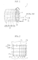
- FIG. 1 is a schematic view of a structure of a quantitative cross-cut testing device (1) of the present embodiment.
- the quantitative cross-cut testing device (1) includes a cut forming mechanism (20) for horizontally and vertically forming cuts (12) in a coating film (11) applied on an inner surface of a sliding bearing (cylindrical base material) to be a work (10).
- the inner circumferential surface of the work (10) is coated with the coating film (11) as described above.
- the quantitative cross-cut testing device (1) is configured so that the work (10) rotates about a shaft center.
- the cut forming mechanism (20) includes a rod-like body (21) arranged parallel to an axial direction of the work (10); and a cut forming section (22) provided with a blade edge protruding from a tip end of the body (21) in a direction perpendicular thereto.
- the body (21) is movable in the axial direction, and is movable in a direction perpendicular to the axial direction between points where the blade edge of the cut forming section (22) is pressed against and is retracted from the inner surface of the work (10).
- first axial cuts (12a) are formed at regular intervals in the coating film (11) (first cutting means (20a)). That is, while intermittently rotating the work (10), the first axial (vertical) cuts (12a) are formed at regular intervals.
- the blade edge is slightly cut into the inner surface of the work (10) with the body (21) of the cut forming mechanism (20) being inserted all the way through the work (10), and then second circumferential (horizontal) cuts (12b) are formed by rotating the work (10) at least one revolution.
- the body (21) of the cut forming mechanism (20) moves so that the blade edge is retracted from the work (10). Subsequently, the body (21) moves back a predetermined distance.
- the blade edge is again pressed against the inner surface of the work (10) at such a position, and then the work (10) rotates to form another second circumferential cut (12b).
- the second circumferential cuts (12b) are intermittently formed.
- FIG. 2 is a development view of the inner surface of the work (10), and illustrates that the first cuts (12a) in one of the groups of vertical and horizontal cuts (12) are formed at regular intervals (L), and the second cuts (12b) in the other group of vertical and horizontal cuts (12) are formed at irregular intervals (W1-W5).
- a peeling process in which a peeling force acts on the coating film (11) after the formation of the cuts (12) is performed by a peeling mechanism (20).
- the peeling mechanism (20) is configured by using the peeling force which naturally acts on the coating film (11) between the second cuts (12b) by narrowing the intervals between the second circumferential cuts (12b) in the formation of the cuts (12). That is, in the quantitative cross-cut testing device (1), the cut forming mechanism (20) also serves as the peeling mechanism (20), and the peeling process is performed at approximately the same time as a cut forming process.
- the intervals between the second cuts (12b) of the coating film (11) peeled off by forming the cuts (12) in the coating film (11) as described above are measured.
- An evaluating process is performed, in which adhesion of the coating film (11) is evaluated based on a peeling state of the coating film (11).
- the intervals between the second cuts (12b) may be measured by using, e.g., a microscope.
- the intervals between the second cuts (12b) formed in the coating film (11) on the work (10) are differentiated, thereby changing a tendency of the coating film (11) to be peeled off (adhesion). Consequently, the coating film (11) tends to be peeled off in a portion having a narrower interval between the second cuts (12b) as compared to a portion having a wider interval between the second cuts (12b).
- the intervals between the second cuts (12b), at which the cells of the coating film (11) are peeled off are evaluated, thereby quantitatively determining the adhesion of the coating film (11). Consequently, the adhesion of the coating film (11) can be more accurately evaluated as compared to a conventional way.
- the intervals between the second cuts (12b) are gradually changed from one end to the other end. If narrow and wide intervals between the second cuts (12b) are mixed, peeled portions are also scattered. Thus, it may be difficult to evaluate the adhesion.
- the peeling is caused in portions between the second cuts (12b), which have the shorter intervals, thereby easily determining the adhesion. That is, a smaller cell where the coating film (11) is peeled off, generates higher adhesion of the coating film (11) to the work (10).
- the second circumferential cuts (12b) are a plurality of second cuts (12b) which are arranged parallel to each other, and which are discontinuous in the axial direction.
- a single second spiral cut (12c) which is continuous in the circumferential and axial directions, and a torsion angle of which is gradually changed may be formed so as to narrow the intervals between the portions of the second cut (12c) from one end to the other end.
- this continuously forms the second circumferential cut (12c), thereby facilitating the working processes.
- the foregoing embodiment may have the following structures.
- the example has been described, where the sliding bearing is used as the work (10).
- the work (10) base material
- the present invention may be applied in order to evaluate adhesion of a coating film (11) formed on a tabular or concave-convex base material.
- circumferential cuts may be formed at regular intervals, and axial cuts may be formed at irregular intervals.
- the cells are changed from a square shape to a rectangular shape.
- cells may be formed in a diamond shape to change the intervals between the cuts (12).
- the cut forming mechanism (20) serves as the peeling mechanism (20) in order not to purposely peel off the coating film (11) by adhesive tapes, etc.
- Such structure is particularly preferred when material such as fluororesin to which a tape is hardly adhered is used as the coating film (11).
- a peeling mechanism (20) only for providing a peeling force by using adhesive tapes, etc. may be provided to perform a peeling process.
- the first cuts (12a) are formed at regular intervals, and the second cuts (12b) are formed at irregular intervals.
- the first cuts (12a) are not necessarily formed at regular intervals, and may be formed at irregular intervals (L1-L5).
- the adhesion of the coating film (11) can be also quantitatively evaluated based on the intervals between the cuts (12a, 12b), at which the cells of the coating film (11) are peeled off.
- FIG. 5 illustrates an example where the first cuts (12a) and the second cuts (12b) are formed so that the intervals therebetween are gradually changed from one end to the other end.
- the way to change the intervals may be altered as necessary.
- the adhesion of the coating film (11) can be also quantitatively determined by measuring the intervals between the cuts (12a, 12b) in the evaluating process.
- a coating film (11) made of polyamide imide (PAI) and polytetrafluoroethylene (PTFE) is applied to an inner circumferential surface of a base material (10) formed by applying a manganese phosphate film coating treatment to cylindrical carbon steel (S45C) material, followed by burning thereof.
- the base material with the prepared coating is used as a test specimen (A).
- a coating film (11) made of PAI and PTFE is applied to an inner circumferential surface of a base material (sintered metal material) (10) formed by sintering iron powder, followed by burning thereof.
- the base material with the prepared coating is used as a test specimen (B).
- a stem treatment is applied to a base material (sintered metal material) (10) formed by sintering iron powder, and then a coating film (11) made of PAI and PTFE is applied to an inner circumferential surface of the base material (10), followed by burning thereof.
- the base material with the prepared coating is used as a test specimen (C).
- an oxide film is formed on a surface of the base material (10) by the steam treatment as described later, and the coating film (11) made of PAI and PTFE is formed thereon.
- test specimens (A), (B), and (C) are examined by both of the quantitative cross-cut test of the present invention, and a cross-cut test according to JIS K 5600-5-6, thereby measuring adhesion of the coating film (11). Specific examples such as sample preparation, testing devices, and.measurement conditions will be described here. Note that vertical and horizontal intervals between cuts (12) are 1 mm in the cross-cut technique according to JIS K 5600-5-6.
- the base material is formed in a cylindrical shape with an inner diameter ⁇ of 34 mm, an outer diameter ⁇ of 44 mm, and a length of 30 mm. Such dimensions are an example, and may be varied.
- a composition of the coating film contains PTFE in an amount of 20-45% by mass.
- the coating film may contain third and fourth fillers such as fluoride and alumina.
- the coating film is formed by a coating technique such as a spray technique and a dispenser technique.
- the thickness upon the burning is 100-150 ⁇ m, and the thickness is reduced to 40-60 ⁇ m by a cutting.
- the burning is performed at 200-300°C for 30-60 minutes.
- the steam treatment is performed in order to form an oxide film on a surface of the sintered material.
- the sintered material is heated within a predetermined temperature range (e.g., 500-560°C) in a water-vapor atmosphere furnace, thereby forming a black oxide film made of Fe 3 O 4 with a predetermined uniform thickness (approximately several microns).
- the sintered material is porous, and the oxide film having the uniform thickness is also formed on inner surfaces of microscopic holes exposed in the surface of the sintered material.
- the coating film (11) made of PAI and PTFE is formed thereon.
- a cutting tool (cut forming section) (22) of a testing device (1) has a blade edge in a good condition.
- a regular-interval spacer with a guide may be used when using a single cutting tool (22).
- adhesive tapes When removing a coating film (11) with no adhesion force, adhesive tapes may be used (e.g., adhesive tapes having an adhesion strength of 10 ⁇ 1N for each 25 mm of width). An approximately 100-300 power optical microscope may be used as an observation instrument used in an evaluating process.
- Shapes of the test specimens are not defined. However, it is desirable to perform a test in three different portions which are more than 5 mm apart from ends of the test specimen. The test specimen having the uniform thickness is desirable.
- the test is performed in at least three different portions of the test specimen, unless otherwise specified, at a temperature of 23 ⁇ 2°C and a relative humidity of 50 ⁇ 5%.
- the test specimen is cured at a temperature of 23 ⁇ 2°C and a relative humidity of 50 ⁇ 5% for at least 16 hours immediately before the test.
- Cuts are formed in the test specimen at an interval of 1 mm in an X direction of a grid pattern, and at intervals of 5-0.1 mm in a Y direction. This forms 4 cuts in the X direction, and 51 cuts in the Y direction, resulting in a grid having the total of 150 cells.
- test specimen is fixed with a vise.
- cuts are manually formed according to specified procedures. Note that a blade portion is checked before the test, and is exchanged to maintain its condition.
- the cutting tool is held so that the blade is perpendicular to a surface of the test specimen. Uniform pressure is added to the cutting tool, and the specified number of cuts are formed in the film-coating portion at a constant cutting rate by using a suitable spacer as necessary.
- the cuts are formed in the X and Y directions at the above-described intervals. All of the cuts should reach the surface of the base material through the coating film. If it is difficult to form the cuts at the interval of 0.1 mm, cuts may be formed without precise measurements so that the intervals therebetween gradually becomes narrower, followed by precisely measuring such intervals by a magnifying glass.
- Adhesive tapes may be used in order to remove the coating film with no adhesion force. The adhesive tapes may be kept for observation.
- Measurement results are evaluated immediately after the coating film with no adhesion is removed. At this point, the peeled coating film is observed from above by using the observation instrument. Intervals where the cells of the coating film are peeled off, and intervals where the cells of the coating film are not peeled off are quantified. Two numerical values are used as necessary to obtain the measurement results. A shorter interval in the peeled portion generates higher adhesion.
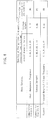
- the measurement results are indicated in a table of FIG. 4 . Peeling widths in the quantitative cross-cut test as shown in the table are measured by using a digital microscope. Each numerical value is an average value of three measurements.
- the quantitative cross-cut test of the present invention results in the test specimen (C) in the example having the peeling width narrower than those of the test specimen (A) and the test specimen (B) in the comparative examples.
- results show stronger adhesion of the coating film (11) to the test specimen (C), and the adhesion strength as compared to the test specimen (A) and the test specimen (B).
- the cross-cut technique according to JIS K 5600-5-6 results in the peeling being caused in the test specimens (A) and (B), and the peeling being not caused in the test specimen (C).
- results show the adhesion strength as in the quantitative cross-cut test of the present invention.
- the cross-cut technique according to JIS K 5600-5-6 can only determine the results as "NG (with peeling)” or “OK (without peeling),” whereas the quantitative cross-cut test of the present embodiment can measure the peeling width to quantify and measure the adhesion.
- the present invention is useful for device and method for obtaining quantitative measurement results in a cross-cut test for measuring coating adhesion to a base material.
Landscapes
- Chemical & Material Sciences (AREA)
- Health & Medical Sciences (AREA)
- Life Sciences & Earth Sciences (AREA)
- Immunology (AREA)
- Analytical Chemistry (AREA)
- Biochemistry (AREA)
- General Health & Medical Sciences (AREA)
- General Physics & Mathematics (AREA)
- Physics & Mathematics (AREA)
- Pathology (AREA)
- Engineering & Computer Science (AREA)
- Food Science & Technology (AREA)
- Medicinal Chemistry (AREA)
- Application Of Or Painting With Fluid Materials (AREA)
- Adhesive Tapes (AREA)
- Sampling And Sample Adjustment (AREA)
Abstract
Description
- The present invention relates to device and method for obtaining quantitative measurement results in a cross-cut test for measuring coating adhesion to a base material.
- A cross-cut test (cross-cut technique) according to Japanese Industrial Standards (JIS) K 5600-5-6 is a test where, after horizontal and vertical cuts are formed at regular intervals in a coating film applied on a base material, an adhesive tape is adhered on and removed from the surface, thereby determining coating adhesion depending on the number of peeled cells.
- For example,
Patent Document 1 discloses that a coating on a base material is cut in a grid pattern, and a jig is bonded to each of the formed cells to apply tensile stress, thereby evaluating adhesion strength of the coating based on its peeling load. - PATENT DOCUMENT 1: Japanese Patent Publication No.
06-16744 - The cross-cut test generally determines the coating adhesion to the base material based on whether or not the coating film is peeled off, and therefore it is difficult to quantitatively measure the coating adhesion. In addition, as for material such as fluororesin to which an adhesive tape is hardly adhered, and non-flat material, it is difficult to remove the tape with good reproducibility.
- In
Patent Document 1, it is necessary to bond the jig to the base material, resulting in the increased number of working processes. Consequently, the measurement cannot be easily performed. - The present invention has been made in view of the foregoing, and it is an object of the present invention to quantitatively measure the coating adhesion to the base material in the cross-cut test, and to reduce the complicated working processes.
- A first aspect of the invention is intended for a cross-cut testing method sequentially performing a cut forming process for vertically and horizontally forming cuts (12) in a coating film (11) applied to a base material (10); a peeling process for making a peeling force act on the coating film (11) after the formation of the cuts (12); and an evaluating process for evaluating adhesion of the coating film (11) based on a peeling state of the coating film (11) after the peeling process.
- The cut forming process of the cross-cut testing method is characterized by forming first cuts (12a) in one of the groups of vertical and horizontal cuts at regular or irregular intervals; and forming second cuts (12b, 12c) in the other group of vertical and horizontal cuts at irregular intervals. The peeling process may be a process performed by using adhesive tapes, etc., or may be a process in which the intervals between the cuts (12) are narrowed, resulting in the coating film (11) being naturally peeled off by the peeling force acting between such cuts (12). That is, the peeling process may be performed at approximately the same time as the cut forming process. If the thickness of the coating film (11) is nonuniform at each evaluation, the adhesion is changed. Thus, it is preferred that the thickness of the coating film (11) is uniform.
- In the first aspect of the invention, a narrower interval between the cuts (12) generates weaker adhesion of the coating film (11) to the base material (10). The coating film (11) tends to be peeled off in a portion having a narrower interval between the cuts (12) as compared to a portion having a wider interval between the cuts (12). Thus, the intervals between the cuts (12), at which cells of the coating film (11) are peeled off, are evaluated, thereby determining the adhesion of the coating film (11).
- A second aspect of the invention is intended for the cross-cut testing method of the first aspect of the invention, in which the cut forming process includes forming the first cuts (12a) at regular intervals, and forming the second cuts (12b, 12c) at irregular intervals.
- In the second aspect of the invention, a narrower interval between the second cuts (12b, 12c) generates weaker adhesion of the coating film (11) to the base material (10). The coating film (11) tends to be peeled off in a portion having a narrower interval between the second cuts (12b, 12c) as compared to a portion having a wider interval between the second cuts (12b, 12c). Thus, the intervals between the second cuts (12b, 12c), at which cells of the coating film (11) are peeled off, are evaluated, thereby determining the adhesion of the coating film (11).
- A third aspect of the invention is intended for the cross-cut testing method of the first or second aspect of the invention, in which the cut forming process includes forming the second cuts (12b, 12c) so that the intervals are gradually increased or decreased from one end to the other end.
- In the third aspect of the invention, the intervals between the second cuts (12b, 12c) are gradually changed from one end to the other end. If narrow and wide intervals between the second cuts (12b, 12c) are mixed, peeled portions may be also scattered. However, in the present invention, the peeling is concentrated in portions having smaller intervals between the second cuts (12b, 12c).
- A fourth aspect of the invention is intended for a cross-cut testing device for performing a cross-cut test for a coating film (11), which includes a cut forming mechanism (20) for vertically and horizontally forming cuts (12) in the coating film (11) applied to a base material (10); and a peeling mechanism (20) for making a peeling force act on the coating film (11) in which the cuts (12) are formed.
- In addition, the cut forming mechanism (20) of the cross-cut testing device is characterized by including first cutting means (20a) for forming first cuts (12a) in one of the groups of vertical and horizontal cuts at regular or irregular intervals; and second cutting means (20b) for forming second cuts (12b, 12c) in the other group of vertical and horizontal cuts at irregular intervals. In such a structure, the peeling mechanism (20) may be a mechanism for purposely peeling the coating film (11) by using adhesive tapes, etc., or may be a mechanism using a peeling force which naturally acts on the coating film (11) between the cuts (12) by narrowing the intervals by the cut forming mechanism (20) (i.e., a structure in which the cut forming mechanism (20) also serves as the peeling mechanism (20)).
- In the fourth aspect of the invention, a narrower interval between the cuts (12) formed by the cut forming mechanism (20) generates weaker adhesion of the coating film (11) to the base material (10). The coating film (11) tends to be peeled off in a portion having a narrower interval between the cuts (12) as compared to a portion having a wider interval between the cuts (12). Thus, the intervals between the cuts (12), at which cells of the coating film (11) are peeled off, are evaluated, thereby determining the adhesion of the coating film (11).
- A fifth aspect of the invention is intended for the cross-cut testing device of the fourth aspect of the invention, in which the first cutting means (20a) forms the first cuts (12a) at regular intervals.
- In the fifth aspect of the invention, a narrower interval between the second cuts (12b, 12c) formed by the cut forming mechanism (20) generates weaker adhesion of the coating film (11) to the base material (10). The coating film (11) tends to be peeled off in a portion having a narrower interval between the second cuts (12b, 12c) as compared to a portion having a wider interval between the second cuts (12b, 12c). Thus, the intervals between the second cuts (12b, 12c), at which cells of the coating film (11) are peeled off, are evaluated, thereby determining the adhesion of the coating film (11).
- A sixth aspect of the invention is intended for the cross-cut testing device of the fourth or fifth aspect of the invention, in which the second cutting means (20b) forms the second cuts (12b, 12c) in the coating film (11) so that the intervals are gradually increased or decreased from one end to the other end.
- In the sixth aspect of the invention, the intervals between the second cuts (12b, 12c) are gradually changed from one end to the other end. If narrow and wide intervals between the second cuts (12b, 12c) are mixed, peeled portions may be also scattered. However, in the present invention, the peeling is concentrated in portions having smaller intervals between the second cuts (12b, 12c).
- A seventh aspect of the invention is intended for the cross-cut testing device of the fifth or sixth aspect of the invention, in which the cut forming mechanism (20) is intended to form the cuts in the coating film (11) formed on the cylindrical base material (10); the first cutting means (20a) forms the first cuts (12a) in an axial direction at regular intervals; and the second cutting means (20b) forms the second cuts (12b, 12c) in a circumferential direction at irregular intervals.
- A eighth aspect of the invention is intended for the cross-cut testing device of the seventh aspect of the invention, in which the second cutting means (20b) forms a plurality of second cuts (12b) which are continuous in the circumferential direction, and which are discontinuous in the axial direction.
- A ninth aspect of the invention is intended for the cross-cut testing device of the seventh aspect of the invention, in which the second cutting means (20b) forms a second cut (12c) which is a single spiral continuous in the circumferential and axial directions, and a torsion angle of which is gradually changed.
- In the seventh to ninth aspects of the invention, e.g., if a coating having smaller friction resistance is formed on a sliding bearing or a bush as machine elements, adhesion of such a coating can be determined based on the first cuts (12a) formed at regular intervals in the axial direction, and the second cuts (12b, 12c) formed at irregular intervals in the circumferential direction. If the cross-cut test of the present invention is performed on the cylindrical base materials (10) as described above for relative comparison, it is preferred that shapes (inner diameters) of the cylinders are identical.
- According to the present invention, the intervals between the cuts (12) formed in the coating film (11) applied to the base material (10) are differentiated, thereby changing the tendency of the coating film (11) to be peeled off (adhesion). Consequently, the coating film (11) tends to be peeled off in the portion having the narrower interval between the cuts (12) as compared to the portion having the wider interval between the cuts (12). Thus, the intervals between the cuts (12), at which the cells of the coating film (11) are peeled off, are evaluated, thereby quantitatively determining the adhesion of the coating film (11). Consequently, the adhesion of the coating film (11) can be more accurately evaluated as compared to a conventional way. In addition, in the present embodiment, it is not necessary to adhere jigs on the base material (10), resulting in a simple measurement. Further, in the present invention, the adhesion of the coating film (11) can be determined without using adhesive tapes. Thus, the present invention is suitable for using material with poor adhesion, e.g., fluororesin, as the coating film (11), the adhesion of which is evaluated.
- According to the second aspect of the invention, the first cuts (12a) are formed at regular intervals, and the second cuts (12b, 12c) are formed at irregular intervals, thereby achieving the advantages as in the first aspect of the invention.
- According to the third aspect of the invention, the intervals between the second cuts (12b, 12c) are gradually changed from one end to the other end. If the narrow and wide intervals between the second cuts (12b, 12c) are mixed, the peeled portions may be also scattered. Thus, it may be difficult to evaluate the adhesion. However, in the present invention, the peeling is concentrated in the portions between the second cuts (12b, 12c), which have the shorter intervals, thereby easily determining the adhesion.
- According to the fourth aspect of the invention, the narrower interval between the cuts (12) formed by the cut forming mechanism (20) generates the weaker adhesion of the coating film (11) to the base material (10). The coating film (11) tends to be peeled off in the portion having the narrower interval between the cuts (12) as compared to the portion having the wider interval between the cuts (12). Thus, the intervals between the cuts (12), at which the cells of the coating film (11) are peeled off, are evaluated, thereby quantitatively determining the adhesion of the coating film (11). Consequently, the adhesion of the coating film (11) can be more accurately evaluated as compared to a conventional way. In addition, in the present invention, it is not necessary to adhere the jigs on the base material (10), resulting in the simple measurement.
- According to the fifth aspect of the invention, the first cuts (12a) are formed at regular intervals, and the second cuts (12b, 12c) are formed at irregular intervals, thereby achieving the advantages as in the fourth aspect of the invention.
- According to the sixth aspect of the invention, the intervals between the second cuts (12b, 12c) are gradually changed from one end to the other end. If the narrow and wide intervals between the second cuts (12b, 12c) are mixed, the peeled portions may be also scattered. Thus, it may be difficult to evaluate the adhesion. However, in the present invention, the peeling is concentrated in the portions between the second cuts (12b, 12c), which have the shorter intervals, thereby easily determining the adhesion.
- According to the seventh to ninth aspects of the invention, if the coating having smaller friction resistance is formed on the sliding bearing, the adhesion of such a coating can be easily determined based on the first cuts (12a) formed at regular intervals in the axial direction, and the second cuts (12b, 12c) formed at irregular intervals in the circumferential direction.
-
- [
FIG. 1] FIG. 1 is a schematic view of a structure of a quantitative cross-cut testing device of an embodiment of the present invention. - [
FIG. 2] FIG. 2 is a development view of an inner surface of a work. - [
FIG. 3] FIG. 3 is a schematic view of a structure of a quantitative cross-cut testing device, which illustrates a variation ofFIG. 1 . - [
FIG. 4] FIG. 4 is a table showing measurement results of an example. - [
FIG. 5] FIG. 5 is a development view of an inner surface of a work of other embodiment. -
- 1
- Cross-Cut Testing Device
- 10
- Base Material
- 11
- Coating Film
- 12
- Cut
- 12a
- Axial (Vertical) Cut (First Cut)
- 12b
- Circumferential (Horizontal) Cut (Second Cut)
- 12c
- Spiral Cut (Second Cut)
- 20
- Cut Forming Mechanism (Peeling Mechanism)
- 20a
- First Cutting Means
- 20b
- Second Cutting Means
- Embodiments of the present invention will be described in detail hereinafter with reference to the drawings. A cross-cut test of the present invention is referred to as a "quantitative cross-cut test" in the present embodiment.
-
FIG. 1 is a schematic view of a structure of a quantitative cross-cut testing device (1) of the present embodiment. The quantitative cross-cut testing device (1) includes a cut forming mechanism (20) for horizontally and vertically forming cuts (12) in a coating film (11) applied on an inner surface of a sliding bearing (cylindrical base material) to be a work (10). The inner circumferential surface of the work (10) is coated with the coating film (11) as described above. Although not illustrated in the figure, the quantitative cross-cut testing device (1) is configured so that the work (10) rotates about a shaft center. - The cut forming mechanism (20) includes a rod-like body (21) arranged parallel to an axial direction of the work (10); and a cut forming section (22) provided with a blade edge protruding from a tip end of the body (21) in a direction perpendicular thereto. The body (21) is movable in the axial direction, and is movable in a direction perpendicular to the axial direction between points where the blade edge of the cut forming section (22) is pressed against and is retracted from the inner surface of the work (10).
- In the quantitative cross-cut testing device (1), an operation is repeated, in which the body (21) of the cut forming mechanism (20) moves back and forth in the axial direction at a position where the blade edge is slightly cut into the inner surface of the work (10) with the work (10) being stopped, and the work (10) rotates at a predetermined angle. Consequently, first axial cuts (12a) are formed at regular intervals in the coating film (11) (first cutting means (20a)). That is, while intermittently rotating the work (10), the first axial (vertical) cuts (12a) are formed at regular intervals.
- Next, the blade edge is slightly cut into the inner surface of the work (10) with the body (21) of the cut forming mechanism (20) being inserted all the way through the work (10), and then second circumferential (horizontal) cuts (12b) are formed by rotating the work (10) at least one revolution. After a single second circumferential cut (12b) is formed, the body (21) of the cut forming mechanism (20) moves so that the blade edge is retracted from the work (10). Subsequently, the body (21) moves back a predetermined distance. The blade edge is again pressed against the inner surface of the work (10) at such a position, and then the work (10) rotates to form another second circumferential cut (12b). As described above, the second circumferential cuts (12b) are intermittently formed. At this point, the distance between the second cuts (12b), over which the body (21) moves back, is gradually shortened, thereby forming the second circumferential cuts (12b) at irregular intervals so that the intervals are gradually narrowed from back to front of the work (10) (second cutting means (20b)).
- As described above, a plurality of unequally-spaced second cuts (12b) continuing in the circumferential direction; and a plurality of equally-spaced first cuts (12a) continuing in the axial direction are formed in the work (10).
FIG. 2 is a development view of the inner surface of the work (10), and illustrates that the first cuts (12a) in one of the groups of vertical and horizontal cuts (12) are formed at regular intervals (L), and the second cuts (12b) in the other group of vertical and horizontal cuts (12) are formed at irregular intervals (W1-W5). - A peeling process in which a peeling force acts on the coating film (11) after the formation of the cuts (12) is performed by a peeling mechanism (20). In the present embodiment, the peeling mechanism (20) is configured by using the peeling force which naturally acts on the coating film (11) between the second cuts (12b) by narrowing the intervals between the second circumferential cuts (12b) in the formation of the cuts (12). That is, in the quantitative cross-cut testing device (1), the cut forming mechanism (20) also serves as the peeling mechanism (20), and the peeling process is performed at approximately the same time as a cut forming process.
- Next, the intervals between the second cuts (12b) of the coating film (11) peeled off by forming the cuts (12) in the coating film (11) as described above are measured. An evaluating process is performed, in which adhesion of the coating film (11) is evaluated based on a peeling state of the coating film (11). At this point, the intervals between the second cuts (12b) may be measured by using, e.g., a microscope.
- According to the present embodiment, the intervals between the second cuts (12b) formed in the coating film (11) on the work (10) are differentiated, thereby changing a tendency of the coating film (11) to be peeled off (adhesion). Consequently, the coating film (11) tends to be peeled off in a portion having a narrower interval between the second cuts (12b) as compared to a portion having a wider interval between the second cuts (12b). Thus, the intervals between the second cuts (12b), at which the cells of the coating film (11) are peeled off, are evaluated, thereby quantitatively determining the adhesion of the coating film (11). Consequently, the adhesion of the coating film (11) can be more accurately evaluated as compared to a conventional way. In addition, in the present embodiment, it is not necessary to adhere jigs or adhesive tapes on the work (10), resulting in a particularly simple measurement.
- In the present embodiment, the intervals between the second cuts (12b) are gradually changed from one end to the other end. If narrow and wide intervals between the second cuts (12b) are mixed, peeled portions are also scattered. Thus, it may be difficult to evaluate the adhesion. However, in the present embodiment, the peeling is caused in portions between the second cuts (12b), which have the shorter intervals, thereby easily determining the adhesion. That is, a smaller cell where the coating film (11) is peeled off, generates higher adhesion of the coating film (11) to the work (10).
- In the example illustrated in
FIG. 1 , the second circumferential cuts (12b) are a plurality of second cuts (12b) which are arranged parallel to each other, and which are discontinuous in the axial direction. However, as illustrated inFIG. 3 , instead of forming the second cuts (12b) parallel to each other in the circumferential direction, and discontinuously forming them in the axial direction, a single second spiral cut (12c) which is continuous in the circumferential and axial directions, and a torsion angle of which is gradually changed may be formed so as to narrow the intervals between the portions of the second cut (12c) from one end to the other end. - In addition to achieve the advantages as in the foregoing embodiment, this continuously forms the second circumferential cut (12c), thereby facilitating the working processes.
- The foregoing embodiment may have the following structures.
- In the foregoing embodiment, the example has been described, where the sliding bearing is used as the work (10). However, the work (10) (base material) does not necessarily have the cylindrical shape, and the present invention may be applied in order to evaluate adhesion of a coating film (11) formed on a tabular or concave-convex base material. Even if the present invention is applied to the cylindrical work (10), circumferential cuts may be formed at regular intervals, and axial cuts may be formed at irregular intervals.
- It is preferred that the cells are changed from a square shape to a rectangular shape. However, cells may be formed in a diamond shape to change the intervals between the cuts (12).
- In the foregoing embodiment, the cut forming mechanism (20) serves as the peeling mechanism (20) in order not to purposely peel off the coating film (11) by adhesive tapes, etc. Such structure is particularly preferred when material such as fluororesin to which a tape is hardly adhered is used as the coating film (11). However, depending on materials of the coating film (11), a peeling mechanism (20) only for providing a peeling force by using adhesive tapes, etc. may be provided to perform a peeling process.
- In the foregoing embodiment, the first cuts (12a) are formed at regular intervals, and the second cuts (12b) are formed at irregular intervals. However, as illustrated in
FIG. 5 , the first cuts (12a) are not necessarily formed at regular intervals, and may be formed at irregular intervals (L1-L5). In such a case, the adhesion of the coating film (11) can be also quantitatively evaluated based on the intervals between the cuts (12a, 12b), at which the cells of the coating film (11) are peeled off.FIG. 5 illustrates an example where the first cuts (12a) and the second cuts (12b) are formed so that the intervals therebetween are gradually changed from one end to the other end. However, the way to change the intervals may be altered as necessary. In such a case, the adhesion of the coating film (11) can be also quantitatively determined by measuring the intervals between the cuts (12a, 12b) in the evaluating process. - The foregoing embodiments have been set forth merely for purposes of preferred examples in nature, and are not intended to limit the applications, and use of the invention.
- In a comparative example (A), a coating film (11) made of polyamide imide (PAI) and polytetrafluoroethylene (PTFE) is applied to an inner circumferential surface of a base material (10) formed by applying a manganese phosphate film coating treatment to cylindrical carbon steel (S45C) material, followed by burning thereof. The base material with the prepared coating is used as a test specimen (A).
- In a comparative example (B), a coating film (11) made of PAI and PTFE is applied to an inner circumferential surface of a base material (sintered metal material) (10) formed by sintering iron powder, followed by burning thereof. The base material with the prepared coating is used as a test specimen (B).
- In an example, a stem treatment is applied to a base material (sintered metal material) (10) formed by sintering iron powder, and then a coating film (11) made of PAI and PTFE is applied to an inner circumferential surface of the base material (10), followed by burning thereof. The base material with the prepared coating is used as a test specimen (C). In such a case, an oxide film is formed on a surface of the base material (10) by the steam treatment as described later, and the coating film (11) made of PAI and PTFE is formed thereon.
- The test specimens (A), (B), and (C) are examined by both of the quantitative cross-cut test of the present invention, and a cross-cut test according to JIS K 5600-5-6, thereby measuring adhesion of the coating film (11). Specific examples such as sample preparation, testing devices, and.measurement conditions will be described here. Note that vertical and horizontal intervals between cuts (12) are 1 mm in the cross-cut technique according to JIS K 5600-5-6.
- Material equivalent to Japan Powder Metallurgy Association (JPMA) SMF 4040 is used as the sintered material. The base material is formed in a cylindrical shape with an inner diameter ϕ of 34 mm, an outer diameter ϕ of 44 mm, and a length of 30 mm. Such dimensions are an example, and may be varied.
- A composition of the coating film contains PTFE in an amount of 20-45% by mass. The coating film may contain third and fourth fillers such as fluoride and alumina.
- The coating film is formed by a coating technique such as a spray technique and a dispenser technique. The thickness upon the burning is 100-150 µm, and the thickness is reduced to 40-60 µm by a cutting. The burning is performed at 200-300°C for 30-60 minutes.
- As for the test specimen (C) of the example, the steam treatment is performed in order to form an oxide film on a surface of the sintered material. Specifically, the sintered material is heated within a predetermined temperature range (e.g., 500-560°C) in a water-vapor atmosphere furnace, thereby forming a black oxide film made of Fe3O4 with a predetermined uniform thickness (approximately several microns). The sintered material is porous, and the oxide film having the uniform thickness is also formed on inner surfaces of microscopic holes exposed in the surface of the sintered material. The coating film (11) made of PAI and PTFE is formed thereon.
- It is necessary that a cutting tool (cut forming section) (22) of a testing device (1) has a blade edge in a good condition. In order to form cuts at regular intervals, a regular-interval spacer with a guide may be used when using a single cutting tool (22).
- When removing a coating film (11) with no adhesion force, adhesive tapes may be used (e.g., adhesive tapes having an adhesion strength of 10±1N for each 25 mm of width). An approximately 100-300 power optical microscope may be used as an observation instrument used in an evaluating process.
- Shapes of the test specimens are not defined. However, it is desirable to perform a test in three different portions which are more than 5 mm apart from ends of the test specimen. The test specimen having the uniform thickness is desirable.
- As described above, the test is performed in at least three different portions of the test specimen, unless otherwise specified, at a temperature of 23±2°C and a relative humidity of 50±5%. In addition, unless otherwise specified, the test specimen is cured at a temperature of 23±2°C and a relative humidity of 50±5% for at least 16 hours immediately before the test.
- Cuts are formed in the test specimen at an interval of 1 mm in an X direction of a grid pattern, and at intervals of 5-0.1 mm in a Y direction. This forms 4 cuts in the X direction, and 51 cuts in the Y direction, resulting in a grid having the total of 150 cells.
- First, the test specimen is fixed with a vise. Next, cuts are manually formed according to specified procedures. Note that a blade portion is checked before the test, and is exchanged to maintain its condition.
- The cutting tool is held so that the blade is perpendicular to a surface of the test specimen. Uniform pressure is added to the cutting tool, and the specified number of cuts are formed in the film-coating portion at a constant cutting rate by using a suitable spacer as necessary.
- The cuts are formed in the X and Y directions at the above-described intervals. All of the cuts should reach the surface of the base material through the coating film. If it is difficult to form the cuts at the interval of 0.1 mm, cuts may be formed without precise measurements so that the intervals therebetween gradually becomes narrower, followed by precisely measuring such intervals by a magnifying glass.
- Adhesive tapes may be used in order to remove the coating film with no adhesion force. The adhesive tapes may be kept for observation.
- Measurement results are evaluated immediately after the coating film with no adhesion is removed. At this point, the peeled coating film is observed from above by using the observation instrument. Intervals where the cells of the coating film are peeled off, and intervals where the cells of the coating film are not peeled off are quantified. Two numerical values are used as necessary to obtain the measurement results. A shorter interval in the peeled portion generates higher adhesion.
- The measurement results are indicated in a table of
FIG. 4 . Peeling widths in the quantitative cross-cut test as shown in the table are measured by using a digital microscope. Each numerical value is an average value of three measurements. - As shown in the table, the quantitative cross-cut test of the present invention results in the test specimen (C) in the example having the peeling width narrower than those of the test specimen (A) and the test specimen (B) in the comparative examples. Thus, such results show stronger adhesion of the coating film (11) to the test specimen (C), and the adhesion strength as compared to the test specimen (A) and the test specimen (B). The cross-cut technique according to JIS K 5600-5-6 results in the peeling being caused in the test specimens (A) and (B), and the peeling being not caused in the test specimen (C). Thus, such results show the adhesion strength as in the quantitative cross-cut test of the present invention. However, the cross-cut technique according to JIS K 5600-5-6 can only determine the results as "NG (with peeling)" or "OK (without peeling)," whereas the quantitative cross-cut test of the present embodiment can measure the peeling width to quantify and measure the adhesion.
- As described above, the present invention is useful for device and method for obtaining quantitative measurement results in a cross-cut test for measuring coating adhesion to a base material.
Claims (9)
- A cross-cut testing method sequentially performing a cut forming process for vertically and horizontally forming cuts (12) in a coating film (11) applied to a base material (10); a peeling process for making a peeling force act on the coating film (11) after the formation of the cuts (12); and an evaluating process for evaluating adhesion of the coating film (11) based on a peeling state of the coating film (11) after the peeling process, the cross-cut testing method characterized in that:the cut forming process includes forming first cuts (12a) in one of the groups of vertical and horizontal cuts at regular or irregular intervals, and forming second cuts (12b, 12c) in the other group of vertical and horizontal cuts at irregular intervals.
- The cross-cut testing method of claim 1, wherein
the cut forming process includes forming the first cuts (12a) at regular intervals, and for forming the second cuts (12b, 12c) at irregular intervals. - The cross-cut testing method of claim 1 or 2, wherein
the cut forming process includes forming the second cuts (12b, 12c) so that the intervals are gradually increased or decreased from one end to the other end. - A cross-cut testing device for performing a cross-cut test for a coating film (11), which includes a cut forming mechanism (20) for vertically and horizontally forming cuts (12) in the coating film (11) applied to a base material (10); and a peeling mechanism (20) for making a peeling force act on the coating film (11) in which the cuts (12) are formed, the cross-cut testing device characterized in that:the cut forming mechanism (20) includes first cutting means (20a) for forming first cuts (12a) in one of the groups of vertical and horizontal cuts at regular or irregular intervals; and second cutting means (20b) for forming second cuts (12b, 12c) in the other group of vertical and horizontal cuts at irregular intervals.
- The cross-cut testing device of claim 4, wherein
the first cutting means (20a) forms the first cuts (12a) at regular intervals. - The cross-cut testing device of claim 4 or 5, wherein
the second cutting means (20b) forms the second cuts (12b, 12c) in the coating film (11) so that the intervals are gradually increased or decreased from one end to the other end. - The cross-cut testing device of claim 5 or 6, wherein
the cut forming mechanism (20) is intended to form the cuts in the coating film (11) formed on the cylindrical base material (10);
the first cutting means (20a) forms the first cuts (12a) in an axial direction at regular intervals; and
the second cutting means (20b) forms the second cuts (12b, 12c) in a circumferential direction at irregular intervals. - The cross-cut testing device of claim 7, wherein
the second cutting means (20b) forms a plurality of second cuts (12b) which are continuous in the circumferential direction, and which are discontinuous in the axial direction. - The cross-cut testing device of claim 7, wherein
the second cutting means (20b) forms a second cut (12c) which is a single spiral continuous in the circumferential and axial directions, and a torsion angle of which is gradually changed.
Applications Claiming Priority (3)
| Application Number | Priority Date | Filing Date | Title |
|---|---|---|---|
| JP2007251588 | 2007-09-27 | ||
| JP2008047589A JP4962353B2 (en) | 2007-09-27 | 2008-02-28 | Cross-cut test method and cross-cut test apparatus |
| PCT/JP2008/002555 WO2009040999A1 (en) | 2007-09-27 | 2008-09-17 | Crosscut testing method, and cross-cut testing device |
Publications (2)
| Publication Number | Publication Date |
|---|---|
| EP2204644A1 true EP2204644A1 (en) | 2010-07-07 |
| EP2204644A4 EP2204644A4 (en) | 2015-08-05 |
Family
ID=40510907
Family Applications (1)
| Application Number | Title | Priority Date | Filing Date |
|---|---|---|---|
| EP08834400.7A Withdrawn EP2204644A4 (en) | 2007-09-27 | 2008-09-17 | QUADRILLAGE TEST METHOD, AND QUADRILLAGE TEST DEVICE |
Country Status (4)
| Country | Link |
|---|---|
| EP (1) | EP2204644A4 (en) |
| JP (1) | JP4962353B2 (en) |
| CN (1) | CN101802590B (en) |
| WO (1) | WO2009040999A1 (en) |
Families Citing this family (5)
| Publication number | Priority date | Publication date | Assignee | Title |
|---|---|---|---|---|
| CN102494999A (en) * | 2011-12-06 | 2012-06-13 | 余姚市供电局 | Method for detecting adhesion of copper coating layer of grounding rod |
| CN102543791A (en) * | 2012-01-20 | 2012-07-04 | 中国科学院上海技术物理研究所 | Film adhesive force quantitative test method with HgCdTe serving as substrate |
| CN103674831A (en) * | 2013-11-28 | 2014-03-26 | 湖州龙鹰电线电缆有限公司 | Method for detecting firmness of aluminum alloy surface coating through utility knife |
| CN111220541A (en) * | 2020-03-17 | 2020-06-02 | 广东省新材料研究所 | Method for testing bonding strength and quality of laser cladding layer |
| CN112304863A (en) * | 2020-11-23 | 2021-02-02 | 西安热工研究院有限公司 | Method for evaluating adhesion of oxide skin on inner wall of superheater reheater pipe of thermal power plant |
Family Cites Families (7)
| Publication number | Priority date | Publication date | Assignee | Title |
|---|---|---|---|---|
| US3389463A (en) * | 1966-10-07 | 1968-06-25 | Gerek Gene | Scoring device for coatings |
| JPS60196640A (en) * | 1984-03-13 | 1985-10-05 | ロバ−ト・マンシン | Coupler for watertightness test of radiator, etc. |
| JPS60196644A (en) * | 1984-03-21 | 1985-10-05 | Toshiba Corp | Adhesion evaluating method |
| JPH01185430A (en) * | 1988-01-21 | 1989-07-25 | Toshiba Corp | Method for evaluating bonding strength of thin film |
| JPH0666996U (en) * | 1993-02-26 | 1994-09-20 | 日本鋼管株式会社 | Automatic cross-cutting device for coating and coating layer of plated steel sheet |
| JP2003098063A (en) * | 2001-09-25 | 2003-04-03 | Sharp Corp | Inspection jig |
| CN1912576A (en) * | 2005-08-12 | 2007-02-14 | 山东大学 | Detection method and device for thick coating adhesion force |
-
2008
- 2008-02-28 JP JP2008047589A patent/JP4962353B2/en not_active Expired - Fee Related
- 2008-09-17 WO PCT/JP2008/002555 patent/WO2009040999A1/en not_active Ceased
- 2008-09-17 CN CN2008801081136A patent/CN101802590B/en not_active Expired - Fee Related
- 2008-09-17 EP EP08834400.7A patent/EP2204644A4/en not_active Withdrawn
Non-Patent Citations (1)
| Title |
|---|
| See references of WO2009040999A1 * |
Also Published As
| Publication number | Publication date |
|---|---|
| WO2009040999A1 (en) | 2009-04-02 |
| CN101802590A (en) | 2010-08-11 |
| JP2009098113A (en) | 2009-05-07 |
| JP4962353B2 (en) | 2012-06-27 |
| CN101802590B (en) | 2012-11-14 |
| EP2204644A4 (en) | 2015-08-05 |
Similar Documents
| Publication | Publication Date | Title |
|---|---|---|
| KR20180127095A (en) | Estimation Apparatus and Method of Creep Crack Rate and Relevant Growth Fracture Parameters for Small Punch Specimen with a Micro Groove | |
| JP4962353B2 (en) | Cross-cut test method and cross-cut test apparatus | |
| JP2009098113A5 (en) | ||
| US10481052B2 (en) | Quality control process to assess the aluminized coating characteristics of hot stamped parts | |
| CN114279785B (en) | Crack resistance evaluation method of laser cladding coating | |
| EP3550280A1 (en) | Apparatus and method for evaluating electrode embrittlement | |
| Zhang et al. | Improving the shear test to determine shear fracture limits for thin stainless steel sheet by shape optimisation | |
| CN112067462A (en) | Method and device for prefabricating cracks on ultrathin brittle material | |
| CN111386456B (en) | Engraving device and method for generating and measuring stress crack corrosion on surface-coated test pieces | |
| JP2010160113A (en) | Reagent and test material and method for detecting cobalt | |
| CN118484890A (en) | Erosion fatigue coupling life prediction method based on defect size | |
| CN115541332A (en) | A preparation and characterization method for surface samples of ball or ring metal parts | |
| Simkulet et al. | Evaluation of tribological characteristics of material prepared by DMLS technology | |
| JP2008292234A (en) | Young's modulus calculation, analysis and calibrating method utilizing instrumented indentation test | |
| Willert et al. | Size effect in micro machining of steel depending on the material state | |
| US20030230138A1 (en) | Method and device for in situ layer thickness determination | |
| Ichikawa et al. | Fracture behavior of micro-sized Ni-P amorphous alloy specimens | |
| CN104458463B (en) | Method for evaluating material sub-surface machining damage layer thickness | |
| Radek et al. | Tribological properties of electro-spark deposited coatings after laser treatment | |
| RU2624616C1 (en) | Method for determining strength of coating adhesion to metal base | |
| KR102230401B1 (en) | Method of manufacturing CuO upon Cu deposition substrate | |
| Abeni et al. | Micro-manufacturing of Powder Bed Fused stainless steel: Micro-machining and Micro-electrical discharge machining | |
| JP3081794B2 (en) | Test Method for Evaluation of Peeling Resistance of Film and Test Piece for Evaluation Test | |
| JPH11300688A (en) | Cutting blade | |
| EP1927848A1 (en) | Method of evaluating press formability of zinc-based plated steel sheet |
Legal Events
| Date | Code | Title | Description |
|---|---|---|---|
| PUAI | Public reference made under article 153(3) epc to a published international application that has entered the european phase |
Free format text: ORIGINAL CODE: 0009012 |
|
| 17P | Request for examination filed |
Effective date: 20100422 |
|
| AK | Designated contracting states |
Kind code of ref document: A1 Designated state(s): AT BE BG CH CY CZ DE DK EE ES FI FR GB GR HR HU IE IS IT LI LT LU LV MC MT NL NO PL PT RO SE SI SK TR |
|
| AX | Request for extension of the european patent |
Extension state: AL BA MK RS |
|
| DAX | Request for extension of the european patent (deleted) | ||
| RA4 | Supplementary search report drawn up and despatched (corrected) |
Effective date: 20150703 |
|
| RIC1 | Information provided on ipc code assigned before grant |
Ipc: G01N 1/04 20060101ALI20150629BHEP Ipc: G01N 19/04 20060101AFI20150629BHEP Ipc: G01N 1/28 20060101ALI20150629BHEP |
|
| STAA | Information on the status of an ep patent application or granted ep patent |
Free format text: STATUS: THE APPLICATION IS DEEMED TO BE WITHDRAWN |
|
| 18D | Application deemed to be withdrawn |
Effective date: 20160202 |