EP2204565A1 - Engine generator set control - Google Patents
Engine generator set control Download PDFInfo
- Publication number
- EP2204565A1 EP2204565A1 EP09015614A EP09015614A EP2204565A1 EP 2204565 A1 EP2204565 A1 EP 2204565A1 EP 09015614 A EP09015614 A EP 09015614A EP 09015614 A EP09015614 A EP 09015614A EP 2204565 A1 EP2204565 A1 EP 2204565A1
- Authority
- EP
- European Patent Office
- Prior art keywords
- engine
- voltage
- function
- selected frequency
- generator
- Prior art date
- Legal status (The legal status is an assumption and is not a legal conclusion. Google has not performed a legal analysis and makes no representation as to the accuracy of the status listed.)
- Withdrawn
Links
- 238000000034 method Methods 0.000 claims description 13
- 230000006870 function Effects 0.000 description 10
- 230000001681 protective effect Effects 0.000 description 9
- 230000006399 behavior Effects 0.000 description 2
- 230000005540 biological transmission Effects 0.000 description 2
- 239000000446 fuel Substances 0.000 description 2
- 238000009434 installation Methods 0.000 description 2
- 230000003287 optical effect Effects 0.000 description 2
- RYGMFSIKBFXOCR-UHFFFAOYSA-N Copper Chemical compound [Cu] RYGMFSIKBFXOCR-UHFFFAOYSA-N 0.000 description 1
- 230000004913 activation Effects 0.000 description 1
- 230000006978 adaptation Effects 0.000 description 1
- 230000008859 change Effects 0.000 description 1
- 238000002485 combustion reaction Methods 0.000 description 1
- 230000000694 effects Effects 0.000 description 1
- 239000000835 fiber Substances 0.000 description 1
- 239000007789 gas Substances 0.000 description 1
- 230000006698 induction Effects 0.000 description 1
- 230000007246 mechanism Effects 0.000 description 1
- 238000012986 modification Methods 0.000 description 1
- 230000004048 modification Effects 0.000 description 1
- 238000005457 optimization Methods 0.000 description 1
- 238000010248 power generation Methods 0.000 description 1
Images

Classifications
-
- F—MECHANICAL ENGINEERING; LIGHTING; HEATING; WEAPONS; BLASTING
- F02—COMBUSTION ENGINES; HOT-GAS OR COMBUSTION-PRODUCT ENGINE PLANTS
- F02D—CONTROLLING COMBUSTION ENGINES
- F02D41/00—Electrical control of supply of combustible mixture or its constituents
- F02D41/0002—Controlling intake air
- F02D41/0007—Controlling intake air for control of turbo-charged or super-charged engines
-
- F—MECHANICAL ENGINEERING; LIGHTING; HEATING; WEAPONS; BLASTING
- F02—COMBUSTION ENGINES; HOT-GAS OR COMBUSTION-PRODUCT ENGINE PLANTS
- F02D—CONTROLLING COMBUSTION ENGINES
- F02D41/00—Electrical control of supply of combustible mixture or its constituents
- F02D41/02—Circuit arrangements for generating control signals
- F02D41/0205—Circuit arrangements for generating control signals using an auxiliary engine speed control
-
- H—ELECTRICITY
- H02—GENERATION; CONVERSION OR DISTRIBUTION OF ELECTRIC POWER
- H02P—CONTROL OR REGULATION OF ELECTRIC MOTORS, ELECTRIC GENERATORS OR DYNAMO-ELECTRIC CONVERTERS; CONTROLLING TRANSFORMERS, REACTORS OR CHOKE COILS
- H02P9/00—Arrangements for controlling electric generators for the purpose of obtaining a desired output
- H02P9/04—Control effected upon non-electric prime mover and dependent upon electric output value of the generator
-
- F—MECHANICAL ENGINEERING; LIGHTING; HEATING; WEAPONS; BLASTING
- F02—COMBUSTION ENGINES; HOT-GAS OR COMBUSTION-PRODUCT ENGINE PLANTS
- F02D—CONTROLLING COMBUSTION ENGINES
- F02D2400/00—Control systems adapted for specific engine types; Special features of engine control systems not otherwise provided for; Power supply, connectors or cabling for engine control systems
- F02D2400/14—Power supply for engine control systems
-
- Y—GENERAL TAGGING OF NEW TECHNOLOGICAL DEVELOPMENTS; GENERAL TAGGING OF CROSS-SECTIONAL TECHNOLOGIES SPANNING OVER SEVERAL SECTIONS OF THE IPC; TECHNICAL SUBJECTS COVERED BY FORMER USPC CROSS-REFERENCE ART COLLECTIONS [XRACs] AND DIGESTS
- Y02—TECHNOLOGIES OR APPLICATIONS FOR MITIGATION OR ADAPTATION AGAINST CLIMATE CHANGE
- Y02T—CLIMATE CHANGE MITIGATION TECHNOLOGIES RELATED TO TRANSPORTATION
- Y02T10/00—Road transport of goods or passengers
- Y02T10/10—Internal combustion engine [ICE] based vehicles
- Y02T10/12—Improving ICE efficiencies
Definitions
- This disclosure relates generally to power generation and distribution systems and, particularly, to a generator set frequency control.
- Engine generator sets are used to produce electric power to power electric loads in a variety of applications and locations.
- a generator and an engine are mounted together along with other accessories on an anchor platform to form an integral unit commonly termed a genset.
- a mechanical rotation is created that drives the generator to produce AC electrical power.
- the frequency of the AC power produced is a direct result of the engine speed and number of rotors on the generator shaft.
- genset manufacturers and distributors desire that gensets be capable of operating at any frequency or voltage rating a customer may require with a minimum of adaptation.
- U.S. Patent No. 6,710,467 issued to Braun et al. discloses a method and apparatus for changing the rating of an engine generator set by selecting a generator set rating using a rating selector included in the generator set control system.
- the generator set rating includes at least an engine rating and voltage.
- Engines typically include a turbocharger.
- a turbocharger that is efficient at one engine speed may not be efficient at another engine speed.
- the turbocharger may not be sized for the alternative frequency. This may result in the engine not receiving the optimum amount of air or in inefficiencies in turbocharger operation.
- a genset manufacturer will either oversize the turbocharger to allow the engine to operate at different speeds, or will recommend that different size turbochargers be used when the genset is operating at different frequencies.
- Variable geometry turbochargers have been developed which use adjustable vanes, nozzles, or the like, to control across a turbine.
- the exhaust flow may be adjusted at the inlet of a turbine through moving vanes to different positions to vary the angle and flow of air as the air hits the turbine blades.
- An engine generator set (genset) control system includes an engine, a generator, a frequency selection interface, a voltage regulator, and a controller.
- the engine includes a variable geometry turbocharger (VGT) and a crankshaft.
- the generator is mechanically coupled to the crankshaft.
- the voltage regulator controls the generator voltage as a function of a selected frequency.
- the controller generates a signal indicative of a desired VGT configuration as a function of the selected frequency.
- a genset control method includes selecting a frequency, configuring a VGT as a function of the selected frequency, controlling an engine speed as a function of the selected frequency, and controlling a generator voltage as a function of the selected frequency.
- the genset control system 100 may include and engine 102, a generator 108, a circuit breaker 110, a controller 114, a frequency selection interface 116, a voltage regulator 122, and protective relays 124, 126, 128, and 130.
- the genset control system 100 may be electrically coupled to an electric load 112.
- electrically coupled means that one member is connected to another member such that electric power flows from that one member to the other.
- cables may electrically connect a load 112 to a power source.
- the connection may also be through a busbar, a circuit breaker 110, or any other electric connector that may be known to an ordinary person skilled in the art now or in the future.
- the engine 102 may be an internal combustion engine.
- the engine 102 may include a variable geometry turbocharger (VGT) 106 and a crankshaft 132.
- VVT variable geometry turbocharger
- the engine 102 may have a speed.
- the VGT may include any turbocharger equipped with one or more devices which may direct and/or control the exhaust flow from the engine 102 onto the turbine blades.
- the devices include aerodynamically-shaped movable vanes in turbine housing near a turbine inlet which may direct exhaust flow from the engine 102 onto the turbine blades.
- the vane angles may be adjusted via an actuator.
- a desired angle of the vanes may vary throughout the engine 102 RPM range to optimize turbine behavior and airflow to the engine.
- the devices may include any one or more devices that would be known by an ordinary person skilled in the art now or in the future that may direct and/or control the exhaust flow from the engine 102 onto the turbine blades.
- An example of a variable geometry turbo charger may be found in U.S. Patent No. 7,426,829 issued to Christopher Greentree .
- the VGT 106 may be configurable by moving the devices to different positions to optimize turbine behavior.
- the VGT 106 may be coupled to the engine 102 air intake manifold to provide pressurized air to the engine 102 through air ducts 138.
- the VGT 106 may be coupled to the engine 102 exhaust manifold through air ducts 138 in such a way that exhaust gases from engine 102 power the turbines in the VGT 106.
- the engine 102 may burn fuel to produce rotational motion in a crankshaft 132.
- the engine 102 speed may be the rotational speed of the crankshaft 132.
- the crankshaft 132 may be mechanically coupled to the generator 108.
- Generator 106 may include any of a variety of electromechanical devices that convert mechanical power into electrical power, typically via Faraday induction effects between moving and stationary current-carrying coils and /or magnets.
- Generator may include an AC asynchronous brushless generator.
- Voltage regulator 122 may control the voltage of power generator 106 produces.
- Voltage regulator 122 may include an electronic circuit or device that maintains the terminal voltage of generator 106 within required limits despite variations in input voltage or load.
- a user may set a desired voltage through voltage regulator 122.
- Voltage regulator 122 may control generator 106 voltage as a function of a desired frequency. When a load is increased during a short period of time, the frequency may droop. Voltage regulator 122 may sense the droop and drop the voltage level for a short time to allow the frequency level to recover. This type of voltage regulator 122 control would be well known to an ordinary person skilled in the art.
- Generator 106 may be electrically connected to the load 112 through the circuit breaker 110.
- Circuit breaker 110 may be any device that makes and breaks the contact between its input and output terminals. Circuit breaker 110 may be capable of clearing fault currents as well as load currents. Circuit breaker 110 may be electronically connected to power protection relays 124, 126, 128, and 130. When power protection relays 124, 126, 128, and 130 sense a power fault, they may generate a signal such that circuit breaker 110 disconnects generator 106 from load 112.
- Power protection relays 124, 126, 128, and 130 may include an overfrequency relay 124, an underfrequency relay 126, an overvoltage relay 128, and an undervoltage relay 130.
- Overfrequency relay 124 may include any device that monitors the frequency level of an electrical power system and determines if the frequency level is above a specific value. When the frequency level is above the specific value, the relay 124 may initiate a trip signal intended to open circuit breaker 110 or other protective devices.
- Underfrequency relay 126 may include any device that monitors the frequency level of an electrical power system and determines if the frequency level is below a specific value. When the frequency level is below the specific value, the relay 126 may initiate a trip signal intended to open circuit breaker 110 or other protective devices.
- Overvoltage relay 128 may include any device that monitors the voltage level of an electrical power system and determines if the voltage level is above a specific value. When the voltage level is over the specific value, the relay 128 may initiate a trip signal intended to open circuit breaker 110 or other protective devices.
- Undervoltage relay 130 may include any device that monitors the voltage level of an electrical power system and determines if the voltage level is below a specific value. When the voltage level is below the specific value, the relay 130 may initiate a trip signal intended to open circuit breaker 110 or other protective devices.
- the controller 114 may include a processor (not shown) and a memory component (not shown).
- the processor may be microprocessors or other processors as known in the art. In some embodiments the processor may be made up of multiple processors.
- the processor may execute instructions for generating a signal indicative of a desired configuration of the VGT 106 as the function of a selected frequency; and generate a signal indicative of a desired engine 102 speed as a function of the selected frequency. Examples of these methods are described below in connection with Figure 2 .
- Such instructions may be read into or incorporated into a computer readable medium, such as the memory component or provided external to processor.
- hard-wired circuitry may be used in place of or in combination with software instructions to implement a steering method. Thus embodiments are not limited to any specific combination of hardware circuitry and software.
- Non-volatile media includes, for example, optical or magnetic disks.
- Volatile media includes dynamic memory.
- Transmission media includes coaxial cables, copper wire and fiber optics, and can also take the form of acoustic or light waves, such as those generated during radio-wave and infra-red data communications.
- Computer-readable media include, for example, a floppy disk, a flexible disk, hard disk, magnetic tape, or any other magnetic medium, a CD-ROM, any other optical medium, punchcards, papertape, any other physical medium with patterns of holes, a RAM, a PROM, and EPROM, a FLASH-EPROM, any other memory chip or cartridge, a carrier wave as described hereinafter, or any other medium from which a computer or processor can read.
- the memory component may include any form of computer-readable media as described above.
- the memory component may include multiple memory components.
- the controller 114 is enclosed in a single housing. In an alternative embodiment, the controller 114 may include a plurality of components operably connected and enclosed in a plurality of housings. The controller 114 may be located on the genset or on-board the engine 102. In another embodiment, the controller 114 may be located on the generator 106. In still other embodiments the controller may be located in a plurality of operably connected locations including on-board the engine 102, on-board the generator 106, and remotely.
- the frequency selection interface (FSI) 116 may include any device that an operator, technician, or other person may operate to select a desired frequency for the genset control system 100.
- the FSI 116 may be located on a control panel mounted on the genset. In an alternative embodiment the FSI 116 may be located remotely from the genset.
- the FSI may include devices with which the operator, technician, or other person interacts physically or they may include voice activation devices.
- the FSI 116 may include a frequency switch 118.
- the frequency switch 118 may be operable to select a desired frequency.
- a switch includes any device, mechanism, or apparatus moveable between two or more positions. Non-limiting examples of a switch include a button, a depressible display area, a slideable member, and a rotatable member.
- the frequency switch 118 may include a scrolling display with a selection device.
- the frequency switch 118 may include any device known by an ordinary person skilled in the art now or in the future to select a desired frequency.
- the desired frequency may have one or more voltages related to it. For example, 50 Hertz may be related to 200V or 400V. 60 Hertz may be related to 240V or 480V.
- the FSI may include a voltage switch 120.
- the voltage switch 120 may be operable to select a desired voltage related to the selected frequency.
- the voltage switch 120 may include a scrolling display with a selection device.
- the voltage switch 120 may include any device known by an ordinary person skilled in the art now or in the future to select a desired voltage.
- the FSI 116 may be coupled to the controller 114 in such a way as to communicate to the controller 114 the selected frequency and the selected voltage.
- the FSI may be coupled to the voltage regulator 122 in such a way as to communicate to the voltage regulator 122 the selected frequency and the selected voltage.
- the FSI 116 may be coupled to the overfrequency relay 124 in such a way as to communicate to overfrequency relay 124 the selected frequency.
- the FSI 116 may be coupled to the underfrequency relay 126 in such a way as to communicate to underfrequency relay 126 the selected frequency.
- the FSI may be coupled to the overvoltage relay 128 in such a way as to communicate to the overvoltage relay 128 the selected voltage.
- the FSI may be coupled to the undervoltage relay 130 in such a way as to communicate to the undervoltage relay 130 the selected voltage.
- the method includes selecting a frequency, configuring a VGT 106 as a function of the selected frequency, and controlling a generator 106 voltage as a function of the selected frequency.
- An operator, technician, or other person may select a desired frequency on the FSI 116, by using the frequency switch 118.
- the desired frequency may have a related voltage.
- the person may select the related voltage with the voltage switch 120.
- the FSI 116 may generate a signal indicative of the desired frequency and related voltage, and send the signal to one or more of the controller 114, voltage regulator 122, and protective relays 124, 126, 128, 130, if the engine 102 is not running. If the engine 102 is running, the FSI 116 may not send the signal.
- the FSI 116 may always send the signal but the controller 114, voltage regulator 122, and protective relays 124, 126, 128, 130, may be able to distinguish that the engine 102 is running and not implement any logic based on the signal.
- the controller 114 may implement logic to determine a desired configuration of the VGT 106.
- the controller 114 may generate a signal indicative of the desired position of the VGT 106.
- An actuator may then move parts within the VGT 106 to the desired configuration.
- the controller 114 may set the engine 102 to a rating that will produce the correct engine 102 speed to produce the desired frequency.
- the FSI 116 may communicate directly or through the controller 114, the desired frequency and related voltage to the voltage regulator 122.
- the FSI 116 may communicate directly of through the controller 114 the desired frequency and related voltage to the protective relays 124, 126, 128, 130.
- the above described genset control system 100 and method may be used to configure a genset to operate in a variety of applications in different locations.
- a technician may select a desired frequency, and the FSI 116 and the controller 114 will set the engine 102 speed, the voltage regulator 122 settings, the protective relay 124, 126, 128, 130 settings, and the VGT 106 configuration automatically. This allows a manufacturer to use the same turbocharger for different ratings.
Landscapes
- Engineering & Computer Science (AREA)
- Chemical & Material Sciences (AREA)
- Combustion & Propulsion (AREA)
- Mechanical Engineering (AREA)
- General Engineering & Computer Science (AREA)
- Power Engineering (AREA)
- Control Of Eletrric Generators (AREA)
Abstract
An engine generator set control system includes an engine, a generator, a frequency selection interface, a voltage regulator, and a controller. The engine includes a variable geometry turbocharger (VGT) and a crankshaft. The controller generates a signal indicative of a desired VGT configuration as a function of the selected frequency.
Description
- This disclosure relates generally to power generation and distribution systems and, particularly, to a generator set frequency control.
- Engine generator sets are used to produce electric power to power electric loads in a variety of applications and locations. A generator and an engine are mounted together along with other accessories on an anchor platform to form an integral unit commonly termed a genset. As fuel is burned within the engine, a mechanical rotation is created that drives the generator to produce AC electrical power. The frequency of the AC power produced is a direct result of the engine speed and number of rotors on the generator shaft.
- Different locations may have different frequency and voltage requirements. For instance, European installations generally require a frequency 50Hertz, and a voltage of 200V or 400V; while United States installations generally require a frequency of 60 Hertz and a voltage of 240V or 480V. Genset manufacturers and distributors desire that gensets be capable of operating at any frequency or voltage rating a customer may require with a minimum of adaptation.
- Recently electronics have been developed to electronically change the engine rating and generator voltage through a customer selection interface. For example,
U.S. Patent No. 6,710,467 issued to Braun et al. , discloses a method and apparatus for changing the rating of an engine generator set by selecting a generator set rating using a rating selector included in the generator set control system. The generator set rating includes at least an engine rating and voltage. - Engines typically include a turbocharger. A turbocharger that is efficient at one engine speed may not be efficient at another engine speed. When a genset frequency is changed, and thus the engine speed, the turbocharger may not be sized for the alternative frequency. This may result in the engine not receiving the optimum amount of air or in inefficiencies in turbocharger operation. Often a genset manufacturer will either oversize the turbocharger to allow the engine to operate at different speeds, or will recommend that different size turbochargers be used when the genset is operating at different frequencies.
- Variable geometry turbochargers have been developed which use adjustable vanes, nozzles, or the like, to control across a turbine. For examples, the exhaust flow may be adjusted at the inlet of a turbine through moving vanes to different positions to vary the angle and flow of air as the air hits the turbine blades.
- It is desirable to have a genset frequency selection that includes optimization of the turbocharger.
- An engine generator set (genset) control system is disclosed. The control system includes an engine, a generator, a frequency selection interface, a voltage regulator, and a controller. The engine includes a variable geometry turbocharger (VGT) and a crankshaft. The generator is mechanically coupled to the crankshaft. The voltage regulator controls the generator voltage as a function of a selected frequency. The controller generates a signal indicative of a desired VGT configuration as a function of the selected frequency.
- A genset control method is also disclosed. The control method includes selecting a frequency, configuring a VGT as a function of the selected frequency, controlling an engine speed as a function of the selected frequency, and controlling a generator voltage as a function of the selected frequency.
-
-
Figure 1 illustrates a genset control system. -
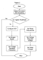
Figure 2 illustrates a genset control method. - Reference will now be made in detail to specific embodiments or features, examples of which are illustrated in the accompanying drawings. Generally, corresponding reference numbers will be used throughout the drawings to refer to the same or corresponding parts.
- Referring to
Figure 1 , an exemplary embodiment of agenset control system 100 is illustrated. Thegenset control system 100 may include andengine 102, agenerator 108, acircuit breaker 110, acontroller 114, afrequency selection interface 116, avoltage regulator 122, andprotective relays genset control system 100 may be electrically coupled to anelectric load 112. - For the purpose of this description, electrically coupled means that one member is connected to another member such that electric power flows from that one member to the other. For example, cables may electrically connect a
load 112 to a power source. The connection may also be through a busbar, acircuit breaker 110, or any other electric connector that may be known to an ordinary person skilled in the art now or in the future. - The
engine 102 may be an internal combustion engine. Theengine 102 may include a variable geometry turbocharger (VGT) 106 and acrankshaft 132. Theengine 102 may have a speed. - The VGT may include any turbocharger equipped with one or more devices which may direct and/or control the exhaust flow from the
engine 102 onto the turbine blades. In one non-limiting example the devices include aerodynamically-shaped movable vanes in turbine housing near a turbine inlet which may direct exhaust flow from theengine 102 onto the turbine blades. The vane angles may be adjusted via an actuator. A desired angle of the vanes may vary throughout theengine 102 RPM range to optimize turbine behavior and airflow to the engine. The devices may include any one or more devices that would be known by an ordinary person skilled in the art now or in the future that may direct and/or control the exhaust flow from theengine 102 onto the turbine blades. An example of a variable geometry turbo charger may be found inU.S. Patent No. 7,426,829 issued to Christopher Greentree . The VGT 106 may be configurable by moving the devices to different positions to optimize turbine behavior. - The VGT 106 may be coupled to the
engine 102 air intake manifold to provide pressurized air to theengine 102 throughair ducts 138. The VGT 106 may be coupled to theengine 102 exhaust manifold throughair ducts 138 in such a way that exhaust gases fromengine 102 power the turbines in the VGT 106. - The
engine 102 may burn fuel to produce rotational motion in acrankshaft 132. Theengine 102 speed may be the rotational speed of thecrankshaft 132. Thecrankshaft 132 may be mechanically coupled to thegenerator 108. -
Generator 106 may include any of a variety of electromechanical devices that convert mechanical power into electrical power, typically via Faraday induction effects between moving and stationary current-carrying coils and /or magnets. Generator may include an AC asynchronous brushless generator. -
Voltage regulator 122 may control the voltage ofpower generator 106 produces.Voltage regulator 122 may include an electronic circuit or device that maintains the terminal voltage ofgenerator 106 within required limits despite variations in input voltage or load. A user may set a desired voltage throughvoltage regulator 122.Voltage regulator 122 may controlgenerator 106 voltage as a function of a desired frequency. When a load is increased during a short period of time, the frequency may droop.Voltage regulator 122 may sense the droop and drop the voltage level for a short time to allow the frequency level to recover. This type ofvoltage regulator 122 control would be well known to an ordinary person skilled in the art. -
Generator 106 may be electrically connected to theload 112 through thecircuit breaker 110.Circuit breaker 110 may be any device that makes and breaks the contact between its input and output terminals.Circuit breaker 110 may be capable of clearing fault currents as well as load currents.Circuit breaker 110 may be electronically connected to power protection relays 124, 126, 128, and 130. When power protection relays 124, 126, 128, and 130 sense a power fault, they may generate a signal such thatcircuit breaker 110disconnects generator 106 fromload 112. - Power protection relays 124, 126, 128, and 130 may include an
overfrequency relay 124, anunderfrequency relay 126, anovervoltage relay 128, and anundervoltage relay 130. -
Overfrequency relay 124 may include any device that monitors the frequency level of an electrical power system and determines if the frequency level is above a specific value. When the frequency level is above the specific value, therelay 124 may initiate a trip signal intended to opencircuit breaker 110 or other protective devices. -
Underfrequency relay 126 may include any device that monitors the frequency level of an electrical power system and determines if the frequency level is below a specific value. When the frequency level is below the specific value, therelay 126 may initiate a trip signal intended to opencircuit breaker 110 or other protective devices. -
Overvoltage relay 128 may include any device that monitors the voltage level of an electrical power system and determines if the voltage level is above a specific value. When the voltage level is over the specific value, therelay 128 may initiate a trip signal intended to opencircuit breaker 110 or other protective devices. -
Undervoltage relay 130 may include any device that monitors the voltage level of an electrical power system and determines if the voltage level is below a specific value. When the voltage level is below the specific value, therelay 130 may initiate a trip signal intended to opencircuit breaker 110 or other protective devices. - The
controller 114 may include a processor (not shown) and a memory component (not shown). The processor may be microprocessors or other processors as known in the art. In some embodiments the processor may be made up of multiple processors. The processor may execute instructions for generating a signal indicative of a desired configuration of theVGT 106 as the function of a selected frequency; and generate a signal indicative of a desiredengine 102 speed as a function of the selected frequency. Examples of these methods are described below in connection withFigure 2 . Such instructions may be read into or incorporated into a computer readable medium, such as the memory component or provided external to processor. In alternative embodiments, hard-wired circuitry may be used in place of or in combination with software instructions to implement a steering method. Thus embodiments are not limited to any specific combination of hardware circuitry and software. - The term "computer-readable medium" as used herein refers to any medium or combination of media that participates in providing instructions to processor for execution. Such a medium may take many forms, including but not limited to, non-volatile media, volatile media, and transmission media. Non-volatile media includes, for example, optical or magnetic disks. Volatile media includes dynamic memory. Transmission media includes coaxial cables, copper wire and fiber optics, and can also take the form of acoustic or light waves, such as those generated during radio-wave and infra-red data communications.
- Common forms of computer-readable media include, for example, a floppy disk, a flexible disk, hard disk, magnetic tape, or any other magnetic medium, a CD-ROM, any other optical medium, punchcards, papertape, any other physical medium with patterns of holes, a RAM, a PROM, and EPROM, a FLASH-EPROM, any other memory chip or cartridge, a carrier wave as described hereinafter, or any other medium from which a computer or processor can read.
- The memory component may include any form of computer-readable media as described above. The memory component may include multiple memory components.
- In the illustrated embodiment, the
controller 114 is enclosed in a single housing. In an alternative embodiment, thecontroller 114 may include a plurality of components operably connected and enclosed in a plurality of housings. Thecontroller 114 may be located on the genset or on-board theengine 102. In another embodiment, thecontroller 114 may be located on thegenerator 106. In still other embodiments the controller may be located in a plurality of operably connected locations including on-board theengine 102, on-board thegenerator 106, and remotely. - The frequency selection interface (FSI) 116 may include any device that an operator, technician, or other person may operate to select a desired frequency for the
genset control system 100. TheFSI 116 may be located on a control panel mounted on the genset. In an alternative embodiment theFSI 116 may be located remotely from the genset. The FSI may include devices with which the operator, technician, or other person interacts physically or they may include voice activation devices. - The
FSI 116 may include afrequency switch 118. Thefrequency switch 118 may be operable to select a desired frequency. A switch includes any device, mechanism, or apparatus moveable between two or more positions. Non-limiting examples of a switch include a button, a depressible display area, a slideable member, and a rotatable member. In alternative embodiments, thefrequency switch 118 may include a scrolling display with a selection device. Thefrequency switch 118 may include any device known by an ordinary person skilled in the art now or in the future to select a desired frequency. - The desired frequency may have one or more voltages related to it. For example, 50 Hertz may be related to 200V or 400V. 60 Hertz may be related to 240V or 480V. The FSI may include a
voltage switch 120. Thevoltage switch 120 may be operable to select a desired voltage related to the selected frequency. In alternative embodiments, thevoltage switch 120 may include a scrolling display with a selection device. Thevoltage switch 120 may include any device known by an ordinary person skilled in the art now or in the future to select a desired voltage. - The
FSI 116 may be coupled to thecontroller 114 in such a way as to communicate to thecontroller 114 the selected frequency and the selected voltage. The FSI may be coupled to thevoltage regulator 122 in such a way as to communicate to thevoltage regulator 122 the selected frequency and the selected voltage. TheFSI 116 may be coupled to theoverfrequency relay 124 in such a way as to communicate tooverfrequency relay 124 the selected frequency. TheFSI 116 may be coupled to theunderfrequency relay 126 in such a way as to communicate tounderfrequency relay 126 the selected frequency. The FSI may be coupled to theovervoltage relay 128 in such a way as to communicate to theovervoltage relay 128 the selected voltage. The FSI may be coupled to theundervoltage relay 130 in such a way as to communicate to theundervoltage relay 130 the selected voltage. - Referring now to Figure 3, an exemplary genset control method is illustrated. The method includes selecting a frequency, configuring a
VGT 106 as a function of the selected frequency, and controlling agenerator 106 voltage as a function of the selected frequency. - An operator, technician, or other person may select a desired frequency on the
FSI 116, by using thefrequency switch 118. The desired frequency may have a related voltage. The person may select the related voltage with thevoltage switch 120. TheFSI 116 may generate a signal indicative of the desired frequency and related voltage, and send the signal to one or more of thecontroller 114,voltage regulator 122, andprotective relays engine 102 is not running. If theengine 102 is running, theFSI 116 may not send the signal. In alternative embodiments, theFSI 116 may always send the signal but thecontroller 114,voltage regulator 122, andprotective relays engine 102 is running and not implement any logic based on the signal. - If the
engine 102 is not running, thecontroller 114 may implement logic to determine a desired configuration of theVGT 106. Thecontroller 114 may generate a signal indicative of the desired position of theVGT 106. An actuator may then move parts within theVGT 106 to the desired configuration. - The
controller 114 may set theengine 102 to a rating that will produce thecorrect engine 102 speed to produce the desired frequency. - The
FSI 116 may communicate directly or through thecontroller 114, the desired frequency and related voltage to thevoltage regulator 122. - The
FSI 116 may communicate directly of through thecontroller 114 the desired frequency and related voltage to theprotective relays - The above described
genset control system 100 and method may be used to configure a genset to operate in a variety of applications in different locations. A technician may select a desired frequency, and theFSI 116 and thecontroller 114 will set theengine 102 speed, thevoltage regulator 122 settings, theprotective relay VGT 106 configuration automatically. This allows a manufacturer to use the same turbocharger for different ratings. - From the foregoing it will be appreciated that, although specific embodiments have been described herein for purposes of illustration, various modifications or variations may be made without deviating from the spirit or scope of inventive features claimed herein. Other embodiments will be apparent to those skilled in the art from consideration of the specification and figures and practice of the arrangements disclosed herein. It is intended that the specification and disclosed examples be considered as exemplary only, with a true inventive scope and spirit being indicated by the following claims and their equivalents.
Claims (10)
- An engine generator set control system, comprising:an engine including a variable geometry turbocharger and a crankshaft,generator mechanically coupled to the crankshaft,a frequency selection interface configured to generate a signal indicative of a selected frequency,a voltage regulator configured to control the voltage output of the generator as a function of the selected frequency, anda controller configured to generate a signal indicative of a desired configuration of the variable geometry turbocharger as a function of the selected frequency and generate a signal indicative of a desired engine speed as a function of the selected frequency.
- The engine generator set control system of claim 1, further comprising:a circuit breaker electrically connected to the generator, andan overfrequency relay configured to control the circuit breaker as a function of the selected frequency.
- The engine generator set control system of claim 1, further comprising:a circuit breaker electrically connected to the generator, andan underfrequency relay configured to control the circuit breaker as a function of the selected frequency.
- The engine generator set control system of claim 1, wherein the selected frequency includes a related voltage, and
further comprising:a circuit breaker electrically connected to the generator, andan overvoltage relay configured to control the circuit breaker as a function of the related voltage. - The engine generator set control system of claim 1, wherein the selected frequency includes a related voltage, and
further comprising:a circuit breaker electrically connected to the generator, andan undervoltage relay configured to control the circuit breaker as a function of the related voltage. - The engine generator set control system of claim 1, wherein the selected frequency includes a related voltage, and the voltage regulator is configured to control the voltage output of the generator as a function of the related voltage.
- A engine generator set control method, comprising:selecting a frequency,configuring a variable geometry turbocharger as a function of the selected frequency,controlling an engine speed as a function of the selected frequency, andcontrolling a generator voltage as a function of the selected frequency.
- The engine generator set control method of claim 7, further comprising controlling a circuit breaker as a function of the selected frequency.
- The engine generator set control method of claim 7, wherein the selected frequency has a related voltage, and
further comprising controlling a generator voltage as a function of the related voltage. - The engine generator set control method of claim 7, wherein the selected frequency has a related voltage, and
further comprising controlling a circuit breaker as a function of the related voltage.
Applications Claiming Priority (2)
| Application Number | Priority Date | Filing Date | Title |
|---|---|---|---|
| US14199208P | 2008-12-31 | 2008-12-31 | |
| US12/633,868 US20100164236A1 (en) | 2008-12-31 | 2009-12-09 | Engine generator set control |
Publications (1)
| Publication Number | Publication Date |
|---|---|
| EP2204565A1 true EP2204565A1 (en) | 2010-07-07 |
Family
ID=41716173
Family Applications (1)
| Application Number | Title | Priority Date | Filing Date |
|---|---|---|---|
| EP09015614A Withdrawn EP2204565A1 (en) | 2008-12-31 | 2009-12-17 | Engine generator set control |
Country Status (2)
| Country | Link |
|---|---|
| US (1) | US20100164236A1 (en) |
| EP (1) | EP2204565A1 (en) |
Cited By (2)
| Publication number | Priority date | Publication date | Assignee | Title |
|---|---|---|---|---|
| FR2998739A1 (en) * | 2012-11-27 | 2014-05-30 | Leroy Somer Moteurs | METHOD FOR CONTROLLING AN ELECTROGEN GROUP |
| CN104850689A (en) * | 2015-04-30 | 2015-08-19 | 昆明理工大学 | Fluid-solid coupling computing method based on fixed grid technology |
Families Citing this family (4)
| Publication number | Priority date | Publication date | Assignee | Title |
|---|---|---|---|---|
| JP5745930B2 (en) * | 2011-05-17 | 2015-07-08 | 本田技研工業株式会社 | Inverter generator |
| US8880249B2 (en) * | 2011-12-30 | 2014-11-04 | General Electric Company | System, method, and computer program for an integrated human-machine interface (HMI) of an engine-generator |
| US10508590B2 (en) * | 2017-02-07 | 2019-12-17 | Kohler Co. | Forced induction engine with electric motor for compressor |
| CN110239369A (en) * | 2019-07-10 | 2019-09-17 | 山东元齐新动力科技有限公司 | Electric machine controller, distance increasing unit, electric car and its distance increasing unit detection method |
Citations (5)
| Publication number | Priority date | Publication date | Assignee | Title |
|---|---|---|---|---|
| WO2003106828A2 (en) * | 2002-06-18 | 2003-12-24 | Ingersoll-Rand Energy Systems Corporation | Microturbine engine system |
| US20040007876A1 (en) * | 2002-07-15 | 2004-01-15 | Braun Andrew N. | Method and apparatus for changing the rating of a electronically controlled engine generator set |
| EP1744446A1 (en) * | 2005-07-15 | 2007-01-17 | The General Electric Company | Methods and systems for operating engine generator sets |
| US7426829B2 (en) | 2004-03-08 | 2008-09-23 | Honeywell | Vane control |
| WO2009024741A1 (en) * | 2007-08-17 | 2009-02-26 | Cummins Turbo Technologies Limited | An engine generator set |
Family Cites Families (9)
| Publication number | Priority date | Publication date | Assignee | Title |
|---|---|---|---|---|
| US5998880A (en) * | 1997-08-07 | 1999-12-07 | General Electric Company | AC locomotive operation without DC current sensor |
| US6037672A (en) * | 1998-02-09 | 2000-03-14 | Lockheed Martin Corporation | Generator having impedance matching prime mover output capability for operation with maximized efficiency |
| US6825575B1 (en) * | 1999-09-28 | 2004-11-30 | Borealis Technical Limited | Electronically controlled engine generator set |
| AT413132B (en) * | 2001-08-03 | 2005-11-15 | Jenbacher Ag | MULTI-CYLINDER STATIONARY INTERNAL COMBUSTION ENGINE |
| US7170262B2 (en) * | 2003-12-24 | 2007-01-30 | Foundation Enterprises Ltd. | Variable frequency power system and method of use |
| US7174714B2 (en) * | 2004-12-13 | 2007-02-13 | Caterpillar Inc | Electric turbocompound control system |
| US7245040B2 (en) * | 2005-07-15 | 2007-07-17 | Honeywell International, Inc. | System and method for controlling the frequency output of dual-spool turbogenerators under varying load |
| US7336000B2 (en) * | 2006-04-20 | 2008-02-26 | Deere & Company | Electrical power regulation for a turbogenerator and generator associated with an internal combustion engine |
| US20080161974A1 (en) * | 2006-08-17 | 2008-07-03 | Gerald Allen Alston | Environmental control and power system |
-
2009
- 2009-12-09 US US12/633,868 patent/US20100164236A1/en not_active Abandoned
- 2009-12-17 EP EP09015614A patent/EP2204565A1/en not_active Withdrawn
Patent Citations (6)
| Publication number | Priority date | Publication date | Assignee | Title |
|---|---|---|---|---|
| WO2003106828A2 (en) * | 2002-06-18 | 2003-12-24 | Ingersoll-Rand Energy Systems Corporation | Microturbine engine system |
| US20040007876A1 (en) * | 2002-07-15 | 2004-01-15 | Braun Andrew N. | Method and apparatus for changing the rating of a electronically controlled engine generator set |
| US6710467B2 (en) | 2002-07-15 | 2004-03-23 | Caterpillar Inc | Method and apparatus for changing the rating of a electronically controlled engine generator set |
| US7426829B2 (en) | 2004-03-08 | 2008-09-23 | Honeywell | Vane control |
| EP1744446A1 (en) * | 2005-07-15 | 2007-01-17 | The General Electric Company | Methods and systems for operating engine generator sets |
| WO2009024741A1 (en) * | 2007-08-17 | 2009-02-26 | Cummins Turbo Technologies Limited | An engine generator set |
Cited By (7)
| Publication number | Priority date | Publication date | Assignee | Title |
|---|---|---|---|---|
| FR2998739A1 (en) * | 2012-11-27 | 2014-05-30 | Leroy Somer Moteurs | METHOD FOR CONTROLLING AN ELECTROGEN GROUP |
| WO2014083487A3 (en) * | 2012-11-27 | 2014-12-11 | Moteurs Leroy-Somer | Method for regulating a generator set |
| CN105122634A (en) * | 2012-11-27 | 2015-12-02 | 利莱森玛电机公司 | Method for regulating a generator set |
| US9739216B2 (en) | 2012-11-27 | 2017-08-22 | Moteurs Leroy-Somer | Method for regulating a generator set |
| CN105122634B (en) * | 2012-11-27 | 2018-11-30 | 利莱森玛电机公司 | Method for regulating a generator set |
| CN104850689A (en) * | 2015-04-30 | 2015-08-19 | 昆明理工大学 | Fluid-solid coupling computing method based on fixed grid technology |
| CN104850689B (en) * | 2015-04-30 | 2019-01-04 | 昆明理工大学 | A kind of fluid and structural simulation method based on fixed mesh technology |
Also Published As
| Publication number | Publication date |
|---|---|
| US20100164236A1 (en) | 2010-07-01 |
Similar Documents
| Publication | Publication Date | Title |
|---|---|---|
| EP2204565A1 (en) | Engine generator set control | |
| EP2733312B1 (en) | Gas turbine engine optimization by electric power transfer | |
| CN1897451B (en) | Methods and systems for operating engine generator sets | |
| US8857192B2 (en) | Accessory gearbox with a starter/generator | |
| EP2330723B1 (en) | Transverse regulated flux machine | |
| US9641112B2 (en) | Protection method for a generator | |
| US20150100180A1 (en) | Electricity generation system | |
| US8823334B2 (en) | Method for starting an electric motor | |
| EP3106648B1 (en) | Actuator control system and method for gas turbine engine | |
| WO2004055960A1 (en) | Gas turbine engine starter generator with multiple windings on each exciter stator pole | |
| EP3422533A1 (en) | Electrical machine apparatus | |
| CA3114460C (en) | Gas turbine engine and method of operating same | |
| JP7731126B2 (en) | Power generation systems and aircraft | |
| EP3484031A1 (en) | Permanent magnet electrical machine | |
| EP3306793B1 (en) | Multiple coil electric generator in turbine engine | |
| Olaiya et al. | High power variable frequency generator for large civil aircraft | |
| Bojoi et al. | Radial flux and axial flux PM machines analysis for more electric engine aircraft applications | |
| US8908336B2 (en) | Fault tolerant electrical machine | |
| WO2025037451A1 (en) | Protection system and protection device | |
| Mellor et al. | A wide speed range permanent magnet generator for future embedded aircraft generation systems | |
| US20230291278A1 (en) | Gas turbine engine equipped with a control system for management of rotor modes using an electric machine | |
| EP4432524A1 (en) | Electric machine | |
| US7560908B2 (en) | Automatic voltage switching for generator voltage change | |
| EP4432523A1 (en) | Electric machine | |
| Tweedy et al. | Electromechanical Analysis of Low Voltage Faults in a Magnetically Coupled Synchronous Generator Set |
Legal Events
| Date | Code | Title | Description |
|---|---|---|---|
| PUAI | Public reference made under article 153(3) epc to a published international application that has entered the european phase |
Free format text: ORIGINAL CODE: 0009012 |
|
| AK | Designated contracting states |
Kind code of ref document: A1 Designated state(s): AT BE BG CH CY CZ DE DK EE ES FI FR GB GR HR HU IE IS IT LI LT LU LV MC MK MT NL NO PL PT RO SE SI SK SM TR |
|
| AX | Request for extension of the european patent |
Extension state: AL BA RS |
|
| STAA | Information on the status of an ep patent application or granted ep patent |
Free format text: STATUS: THE APPLICATION IS DEEMED TO BE WITHDRAWN |
|
| 18D | Application deemed to be withdrawn |
Effective date: 20110108 |