EP2204549A2 - Variable position guide vane actuation system and method - Google Patents
Variable position guide vane actuation system and method Download PDFInfo
- Publication number
- EP2204549A2 EP2204549A2 EP09179376A EP09179376A EP2204549A2 EP 2204549 A2 EP2204549 A2 EP 2204549A2 EP 09179376 A EP09179376 A EP 09179376A EP 09179376 A EP09179376 A EP 09179376A EP 2204549 A2 EP2204549 A2 EP 2204549A2
- Authority
- EP
- European Patent Office
- Prior art keywords
- variable position
- position guide
- turbine
- actuation system
- guide vane
- Prior art date
- Legal status (The legal status is an assumption and is not a legal conclusion. Google has not performed a legal analysis and makes no representation as to the accuracy of the status listed.)
- Granted
Links
Images
Classifications
-
- F—MECHANICAL ENGINEERING; LIGHTING; HEATING; WEAPONS; BLASTING
- F01—MACHINES OR ENGINES IN GENERAL; ENGINE PLANTS IN GENERAL; STEAM ENGINES
- F01D—NON-POSITIVE DISPLACEMENT MACHINES OR ENGINES, e.g. STEAM TURBINES
- F01D17/00—Regulating or controlling by varying flow
- F01D17/10—Final actuators
- F01D17/12—Final actuators arranged in stator parts
- F01D17/14—Final actuators arranged in stator parts varying effective cross-sectional area of nozzles or guide conduits
- F01D17/16—Final actuators arranged in stator parts varying effective cross-sectional area of nozzles or guide conduits by means of nozzle vanes
- F01D17/162—Final actuators arranged in stator parts varying effective cross-sectional area of nozzles or guide conduits by means of nozzle vanes for axial flow, i.e. the vanes turning around axes which are essentially perpendicular to the rotor centre line
-
- F—MECHANICAL ENGINEERING; LIGHTING; HEATING; WEAPONS; BLASTING
- F04—POSITIVE - DISPLACEMENT MACHINES FOR LIQUIDS; PUMPS FOR LIQUIDS OR ELASTIC FLUIDS
- F04D—NON-POSITIVE-DISPLACEMENT PUMPS
- F04D29/00—Details, component parts, or accessories
- F04D29/40—Casings; Connections of working fluid
- F04D29/52—Casings; Connections of working fluid for axial pumps
- F04D29/54—Fluid-guiding means, e.g. diffusers
- F04D29/56—Fluid-guiding means, e.g. diffusers adjustable
- F04D29/563—Fluid-guiding means, e.g. diffusers adjustable specially adapted for elastic fluid pumps
Definitions
- the disclosed invention relates to a system for actuating variable position guide vanes in a turbine engine. More specifically the invention relates to actuating the variable position guide vanes by moving a structure in operable communication with a plurality of the variable position guide vanes.
- Aerodynamic efficiency of the vanes of a turbine engine is an important factor in the overall operational efficiency of the engine. Operators rotate the vanes in an attempt to improve the aerodynamic performance at different power settings of the turbine. Systems and methods to improve precision and control of rotation of the multitude of vanes in a turbine engine is of value to operators in the industry.
- a turbine variable position guide vane actuation system includes, a plurality of variable position guide vanes, a plurality of actuators with each actuator in operable communication with one of the plurality of variable position guide vanes, and each of the plurality of actuators having a pin.
- the system further having at least one structure, movable parallel to an axis of the turbine, having a plurality of slots and each of the plurality of slots is in operable communication with one of the pins.
- Turbine engines such as, gas turbine engines for power generation, for example, have stationary guide vanes and rotating guide vanes. Compressed air flows past both types of guide vanes during operation of the turbine. Performance of the turbine can vary depending upon, among other things, angles of the stationary guide vanes. During different operating conditions, however, different guide vane angles may be preferred. As such, having guide vanes, wherein angles of the vanes are variable, has benefits to the turbine operator. Systems and methods for adjusting the variable guide vanes are described in detail below.
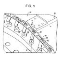
- the system 10 includes, a plurality of variable position guide vanes 14 with an actuator 18, shown herein as a lever, attached to each one of the variable position guide vanes 14, and at least one structure 22, shown herein as a plate, engaged with a plurality of the levers 18.
- the plate 22 is configured to be moved in a direction parallel to an axis of the turbine 26 to cause rotational motion of each of the levers 18, engaged therewith, and consequently to rotate the variable position guide vanes 14 attached thereto.
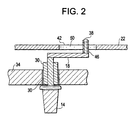
- FIG. 2 a cross sectional view through one of the variable position guide vanes 14, the lever 18 and the plate 22, of FIG. 1 , along arrows 2-2, is shown.
- a bushing or bearing 30 rotationally, mounts each of the variable position guide vanes 14 to a casing 34 of the turbine 26.
- a pin 38 extends from each of the levers 18 to engage with a slot 42 of the plate 22.
- a sleeve 46 can be rotationally engaged with each of the pins 38 to reduce frictional engagement between the pins 38 and walls 50 of the slots 42.
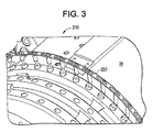
- FIG. 3 an alternate embodiment of a turbine variable position guide vane actuation system 210 with a plate 222 disclosed herein is illustrated.
- the plate 222 forms a ring perimetrically around a significant portion of the turbine 26.
- the plate 222 can be a continuous ring that encircles the casing 34 and actuates all of the levers 18, or be segmented to actuate any selected number of the levers 18 desired.
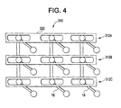
- FIG. 4 yet another alternate embodiment of a turbine variable position guide vane actuation system 310 with plates 322 disclosed herein is illustrated.
- the plates 322 are a variation of the structures 22.
- the plates 322 are configured to actuate levers 18 on multiple stages simultaneously.
- the plates 322 actuate variable position guide vanes 14 from different stages 312A, 312B and 312C of the turbine 26.
- Such a "ganged” system can significantly simplify the linkages required to actuate a multitude of the variable position guide vanes 14 at once. Two or more stages can be “ganged” together forming one or more "gangs,” for example. This variation of the "ganged” system can also be used for the plates 222.
Landscapes
- Engineering & Computer Science (AREA)
- Mechanical Engineering (AREA)
- General Engineering & Computer Science (AREA)
- Control Of Turbines (AREA)
- Structures Of Non-Positive Displacement Pumps (AREA)
- Turbine Rotor Nozzle Sealing (AREA)
- Supercharger (AREA)
Abstract
Description
- The disclosed invention relates to a system for actuating variable position guide vanes in a turbine engine. More specifically the invention relates to actuating the variable position guide vanes by moving a structure in operable communication with a plurality of the variable position guide vanes.
- Aerodynamic efficiency of the vanes of a turbine engine is an important factor in the overall operational efficiency of the engine. Operators rotate the vanes in an attempt to improve the aerodynamic performance at different power settings of the turbine. Systems and methods to improve precision and control of rotation of the multitude of vanes in a turbine engine is of value to operators in the industry.
- Disclosed herein is a turbine variable position guide vane actuation system. The system includes, a plurality of variable position guide vanes, a plurality of actuators with each actuator in operable communication with one of the plurality of variable position guide vanes, and each of the plurality of actuators having a pin. The system further having at least one structure, movable parallel to an axis of the turbine, having a plurality of slots and each of the plurality of slots is in operable communication with one of the pins.
- The following descriptions should not be considered limiting in any way. With reference to the accompanying drawings, like elements are numbered alike. In the drawings:
-
FIG. 1 depicts a partial perspective view of a turbine variable position guide vane actuation system disclosed herein; -
FIG. 2 depicts a cross sectional view of a portion of the turbine variable position guide vane actuation system ofFIG. 1 taken along arrows 2-2; -
FIG. 3 depicts a partial perspective view of an alternate variable position guide vane actuation system disclosed herein; and -
FIG. 4 depicts a partial perspective view of another alternate variable position guide vane actuation system disclosed herein. - A detailed description of one or more embodiments of the disclosed apparatus and method are presented herein by way of exemplification and not limitation with reference to the Figures.
- Turbine engines, such as, gas turbine engines for power generation, for example, have stationary guide vanes and rotating guide vanes. Compressed air flows past both types of guide vanes during operation of the turbine. Performance of the turbine can vary depending upon, among other things, angles of the stationary guide vanes. During different operating conditions, however, different guide vane angles may be preferred. As such, having guide vanes, wherein angles of the vanes are variable, has benefits to the turbine operator. Systems and methods for adjusting the variable guide vanes are described in detail below.
- Referring to
FIG. 1 , an embodiment of a turbine variable position guidevane actuation system 10 disclosed herein is illustrated. Thesystem 10 includes, a plurality of variableposition guide vanes 14 with anactuator 18, shown herein as a lever, attached to each one of the variableposition guide vanes 14, and at least onestructure 22, shown herein as a plate, engaged with a plurality of thelevers 18. Theplate 22 is configured to be moved in a direction parallel to an axis of theturbine 26 to cause rotational motion of each of thelevers 18, engaged therewith, and consequently to rotate the variableposition guide vanes 14 attached thereto. - Referring to
FIG. 2 , a cross sectional view through one of the variableposition guide vanes 14, thelever 18 and theplate 22, ofFIG. 1 , along arrows 2-2, is shown. A bushing or bearing 30 rotationally, mounts each of the variableposition guide vanes 14 to acasing 34 of theturbine 26. Apin 38 extends from each of thelevers 18 to engage with aslot 42 of theplate 22. Optionally, asleeve 46 can be rotationally engaged with each of thepins 38 to reduce frictional engagement between thepins 38 andwalls 50 of theslots 42. - By moving the
plates 22 parallel to an axis of theturbine 26 the lateral or radial instability (as the case may be) that occurs in typical systems that have theplate 22 move circumferentially with respect to theturbine 26 can be reduced. In addition to decreasing friction between thesleeve 46 and theplate 22, in comparison to typical systems, embodiments disclosed herein can more easily control the precision of the rotational motion of the variableposition guide vanes 14. This ease of control is due to a reduced offset between the linear motion of theplate 22 and the rotational motion of the variable position guide vanes 14, as compared to a circumferential motion of a plate. This control precision can be maintained in alternate embodiments as will be described below. - Referring to
FIG. 3 , an alternate embodiment of a turbine variable position guidevane actuation system 210 with aplate 222 disclosed herein is illustrated. Unlike theplates 22 shown above that each functionally engage with few of thelevers 18, theplate 222 forms a ring perimetrically around a significant portion of theturbine 26. In fact, theplate 222 can be a continuous ring that encircles thecasing 34 and actuates all of thelevers 18, or be segmented to actuate any selected number of thelevers 18 desired. For assembly and removal purposes splitting theplate 222 into at least two portions, with each encircling approximately half of thecasing 34, may be advantageous. - Referring to
FIG. 4 , yet another alternate embodiment of a turbine variable position guidevane actuation system 310 withplates 322 disclosed herein is illustrated. Theplates 322 are a variation of thestructures 22. Theplates 322 are configured to actuatelevers 18 on multiple stages simultaneously. Theplates 322 actuate variable position guide vanes 14 fromdifferent stages turbine 26. Such a "ganged" system can significantly simplify the linkages required to actuate a multitude of the variableposition guide vanes 14 at once. Two or more stages can be "ganged" together forming one or more "gangs," for example. This variation of the "ganged" system can also be used for theplates 222. - While the invention has been described with reference to an exemplary embodiment or embodiments, it will be understood by those skilled in the art that various changes may be made and equivalents may be substituted for elements thereof without departing from the scope of the invention. In addition, many modifications may be made to adapt a particular situation or material to the teachings of the invention without departing from the essential scope thereof. Therefore, it is intended that the invention not be limited to the particular embodiment disclosed as the best mode contemplated for carrying out this invention, but that the invention will include all embodiments falling within the scope of the claims. Also, in the drawings and the description, there have been disclosed exemplary embodiments of the invention and, although specific terms may have been employed, they are unless otherwise stated used in a generic and descriptive sense only and not for purposes of limitation, the scope of the invention therefore not being so limited. Moreover, the use of the terms first, second, etc. do not denote any order or importance, but rather the terms first, second, etc. are used to distinguish one element from another. Furthermore, the use of the terms a, an, etc. do not denote a limitation of quantity, but rather denote the presence of at least one of the referenced item.
Claims (8)
- A turbine variable position guide vane actuation system (10), comprising:a plurality of variable position guide vanes (14);a plurality of actuators (18) with each actuator (18) being in operable communication with one of the plurality of variable position guide vanes (14), and each of the plurality of actuators (18) having a pin (38); andat least one structure (22) being movable parallel to an axis of the turbine (26) having a plurality of slots (42) each of the plurality of slots (42) being in operable communication with one of the pins (38).
- The turbine variable position guide vane actuation system (10) of claim 1, wherein the at least one structure (22) is arcuate shaped and is substantially concentric with a casing (34) of the turbine (26).
- The turbine variable position guide vane actuation system (10) of claim 1 or claim 2, wherein movement of the at least one structure (22) in a direction parallel to an axis of the turbine (26) causes rotation of each of the actuators (18) in operable communication therewith.
- The turbine variable position guide vane actuation system (10) of claim 3, wherein rotation of each of the actuators (18) causes rotation of one of the variable position guide vanes (14) in operable communication therewith.
- The turbine variable position guide vane actuation system (10) of any preceding claim, wherein each pin (38) has a sleeve (46) rotationally mounted thereto.
- The turbine variable position guide vane actuation system (10) of any preceding claim, wherein the plurality of actuators (18) are a plurality of levers (18).
- The turbine variable position guide vane actuation system (10) of any preceding claim, wherein the at least one structure (22) is at least one plate (22).
- The turbine variable position guide vane actuation system (10) of any preceding claim, wherein a plurality of actuators (18) in operable communication with one of the at least one structure (22) are in operable communication with variable position guide vanes (14) from more than one stage of the turbine (26).
Applications Claiming Priority (1)
| Application Number | Priority Date | Filing Date | Title |
|---|---|---|---|
| US12/349,160 US8297918B2 (en) | 2009-01-06 | 2009-01-06 | Variable position guide vane actuation system and method |
Publications (3)
| Publication Number | Publication Date |
|---|---|
| EP2204549A2 true EP2204549A2 (en) | 2010-07-07 |
| EP2204549A3 EP2204549A3 (en) | 2011-01-26 |
| EP2204549B1 EP2204549B1 (en) | 2015-10-28 |
Family
ID=41693028
Family Applications (1)
| Application Number | Title | Priority Date | Filing Date |
|---|---|---|---|
| EP09179376.0A Not-in-force EP2204549B1 (en) | 2009-01-06 | 2009-12-16 | Variable position guide vane actuation system |
Country Status (4)
| Country | Link |
|---|---|
| US (1) | US8297918B2 (en) |
| EP (1) | EP2204549B1 (en) |
| JP (1) | JP5599618B2 (en) |
| CN (1) | CN101892874B (en) |
Cited By (3)
| Publication number | Priority date | Publication date | Assignee | Title |
|---|---|---|---|---|
| EP2423449A1 (en) * | 2010-08-31 | 2012-02-29 | Nuovo Pignone S.p.A. | Turbomachine actuation system and corresponding method |
| WO2015092197A1 (en) * | 2013-12-19 | 2015-06-25 | Snecma | Turbine engine compressor, in particular of an aeroplane turboprop or turbofan |
| DE102014001034A1 (en) | 2014-01-25 | 2015-07-30 | MTU Aero Engines AG | flow machine |
Families Citing this family (24)
| Publication number | Priority date | Publication date | Assignee | Title |
|---|---|---|---|---|
| US8348600B2 (en) * | 2008-05-27 | 2013-01-08 | United Technologies Corporation | Gas turbine engine having controllable inlet guide vanes |
| US8727697B2 (en) * | 2010-03-27 | 2014-05-20 | Rolls-Royce Corporation | Variable vane actuation system and method |
| US8915703B2 (en) * | 2011-07-28 | 2014-12-23 | United Technologies Corporation | Internally actuated inlet guide vane for fan section |
| US9394804B2 (en) | 2012-01-24 | 2016-07-19 | Florida Institute Of Technology | Apparatus and method for rotating fluid controlling vanes in small turbine engines and other applications |
| EP2984315B1 (en) * | 2013-04-08 | 2018-07-11 | United Technologies Corporation | Annular airflow actuation system for variable cycle gas turbine engines |
| WO2014205816A1 (en) * | 2013-06-28 | 2014-12-31 | Siemens Aktiengesellschaft | Guide vane actuator of a compressor and a compressor using it |
| US9932851B2 (en) | 2013-12-30 | 2018-04-03 | Rolls-Royce North American Technologies, Inc. | Active synchronizing ring |
| JP6194553B2 (en) * | 2014-01-27 | 2017-09-13 | 三菱日立パワーシステムズ株式会社 | POSITION ADJUSTING DEVICE, ROTARY MACHINE HAVING THE SAME, AND POSITION ADJUSTING METHOD |
| US9422859B2 (en) * | 2014-03-05 | 2016-08-23 | GM Global Technology Operations LLC | Adaptable turbocharger control |
| FR3038666B1 (en) * | 2015-07-09 | 2017-07-07 | Snecma | AUB CONTROL RING WITH VARIABLE SHIFT FOR A TURBOMACHINE |
| US11073090B2 (en) * | 2016-03-30 | 2021-07-27 | General Electric Company | Valved airflow passage assembly for adjusting airflow distortion in gas turbine engine |
| US10794219B2 (en) * | 2017-09-14 | 2020-10-06 | Rolls-Royce Corporation | Axial case ring to maximize thrust bushing contact area of variable vane |
| GB201717091D0 (en) * | 2017-10-18 | 2017-11-29 | Rolls Royce Plc | A variable vane actuation arrangement |
| DE102017222209A1 (en) * | 2017-12-07 | 2019-06-13 | MTU Aero Engines AG | Guide vane connection and turbomachine |
| US10815802B2 (en) * | 2018-12-17 | 2020-10-27 | Raytheon Technologies Corporation | Variable vane assemblies configured for non-axisymmetric actuation |
| US11002142B2 (en) * | 2019-01-21 | 2021-05-11 | Raytheon Technologies Corporation | Thermally compensated synchronization ring of a variable stator vane assembly |
| US11560810B1 (en) | 2021-07-20 | 2023-01-24 | Rolls-Royce North American Technologies Inc. | Variable vane actuation system and method for gas turbine engine performance management |
| US12146414B2 (en) | 2022-10-21 | 2024-11-19 | Rolls-Royce North American Technologies Inc. | Stator vane control system with magnetic actuation rotor for gas turbine engines |
| US12270309B2 (en) | 2022-10-21 | 2025-04-08 | Rolls-Royce North American Technologies Inc. | Variable stator vane assembly with magnetic actuation rotor for gas turbine engines |
| US12000293B1 (en) | 2022-12-30 | 2024-06-04 | Rolls-Royce North American Technologies Inc. | Systems and methods for multi-dimensional variable vane stage rigging utilizing coupling mechanisms |
| US12146415B2 (en) | 2022-12-30 | 2024-11-19 | Rolls-Royce North American Technologies Inc. | Systems and methods for multi-dimensional variable vane stage rigging utilizing adjustable bracket plates |
| US11982193B1 (en) | 2022-12-30 | 2024-05-14 | Rolls-Royce North American Technologies Inc. | Systems and methods for multi-dimensional variable vane stage rigging utilizing adjustable inclined mechanisms |
| US11834966B1 (en) | 2022-12-30 | 2023-12-05 | Rolls-Royce North American Technologies Inc. | Systems and methods for multi-dimensional variable vane stage rigging utilizing adjustable alignment mechanisms |
| US12000292B1 (en) | 2022-12-30 | 2024-06-04 | Rolls-Royce North American Technologies Inc. | Systems and methods for multi-dimensional variable vane stage rigging |
Family Cites Families (10)
| Publication number | Priority date | Publication date | Assignee | Title |
|---|---|---|---|---|
| CH404841A (en) * | 1963-09-27 | 1965-12-31 | Bbc Brown Boveri & Cie | Turbomachinery with adjustable blades |
| CH485124A (en) * | 1968-01-15 | 1970-01-31 | Sulzer Ag | Multi-stage axial compressor |
| US3861822A (en) * | 1974-02-27 | 1975-01-21 | Gen Electric | Duct with vanes having selectively variable pitch |
| JPS5859400A (en) | 1981-10-02 | 1983-04-08 | Hitachi Ltd | Variable stator blade mounting angle device for multi-stage axial compressor |
| CH661772A5 (en) * | 1983-05-31 | 1987-08-14 | Escher Wyss Ag | AXIAL TURBO MACHINE. |
| GB8722714D0 (en) * | 1987-09-26 | 1987-11-04 | Rolls Royce Plc | Variable guide vane arrangement for compressor |
| GB9203168D0 (en) * | 1992-02-13 | 1992-04-01 | Rolls Royce Plc | Guide vanes for gas turbine engines |
| US6106227A (en) * | 1998-02-27 | 2000-08-22 | United Technologies Corporation | Roller assembly for guiding an actuating ring |
| JP4008404B2 (en) * | 2002-10-18 | 2007-11-14 | 三菱重工業株式会社 | Variable displacement exhaust turbocharger |
| US8435000B2 (en) * | 2008-03-07 | 2013-05-07 | Rolls-Royce Corporation | Variable vane actuation system |
-
2009
- 2009-01-06 US US12/349,160 patent/US8297918B2/en not_active Expired - Fee Related
- 2009-12-16 EP EP09179376.0A patent/EP2204549B1/en not_active Not-in-force
-
2010
- 2010-01-05 JP JP2010000298A patent/JP5599618B2/en not_active Expired - Fee Related
- 2010-01-06 CN CN201010003821.2A patent/CN101892874B/en not_active Expired - Fee Related
Cited By (10)
| Publication number | Priority date | Publication date | Assignee | Title |
|---|---|---|---|---|
| EP2423449A1 (en) * | 2010-08-31 | 2012-02-29 | Nuovo Pignone S.p.A. | Turbomachine actuation system and corresponding method |
| ITCO20100050A1 (en) * | 2010-08-31 | 2012-03-01 | Nuovo Pignone Spa | DRIVING SYSTEM FOR TURBOMACHINE AND METHOD |
| CN102400948A (en) * | 2010-08-31 | 2012-04-04 | 诺沃皮尼奥内有限公司 | Turbomachine actuation system and corresponding method |
| US8944747B2 (en) | 2010-08-31 | 2015-02-03 | Nuovo Pignone S.P.A. | Turbomachine actuation system and method |
| WO2015092197A1 (en) * | 2013-12-19 | 2015-06-25 | Snecma | Turbine engine compressor, in particular of an aeroplane turboprop or turbofan |
| FR3015594A1 (en) * | 2013-12-19 | 2015-06-26 | Snecma | TURBOMACHINE COMPRESSOR, ESPECIALLY AIRCRAFT TURBOPROPULSER OR AIRCRAFT TURBINEACTOR |
| RU2670473C1 (en) * | 2013-12-19 | 2018-10-23 | Снекма | Turbine engine compressor, in particular of aeroplane turboprop or turbofan |
| US10590794B2 (en) | 2013-12-19 | 2020-03-17 | Safran Aircraft Engines | Turbine engine compressor, in particular of an aeroplane turboprop or turbofan |
| DE102014001034A1 (en) | 2014-01-25 | 2015-07-30 | MTU Aero Engines AG | flow machine |
| DE102014001034B4 (en) | 2014-01-25 | 2020-01-02 | MTU Aero Engines AG | flow machine |
Also Published As
| Publication number | Publication date |
|---|---|
| US8297918B2 (en) | 2012-10-30 |
| JP2010159749A (en) | 2010-07-22 |
| US20100172744A1 (en) | 2010-07-08 |
| EP2204549A3 (en) | 2011-01-26 |
| EP2204549B1 (en) | 2015-10-28 |
| CN101892874B (en) | 2015-03-11 |
| CN101892874A (en) | 2010-11-24 |
| JP5599618B2 (en) | 2014-10-01 |
Similar Documents
| Publication | Publication Date | Title |
|---|---|---|
| US8297918B2 (en) | Variable position guide vane actuation system and method | |
| EP2204550A2 (en) | Variable position guide vane actuation system and method | |
| US10634000B2 (en) | Method and configuration for improved variable vane positioning | |
| US10508660B2 (en) | Apparatus and method for positioning a variable vane | |
| EP1808579B1 (en) | Actuation system for variable stator vanes | |
| US10927699B2 (en) | Variable-pitch blade control ring for a turbomachine | |
| EP2971599B1 (en) | Variable vane drive system | |
| EP2211026B1 (en) | A variable stator vane assembly in a gas turbine engine | |
| US9103228B2 (en) | Variable stator vane control system | |
| JP5220351B2 (en) | Turbomachine stator including a stage of stator blades actuated by a self-aligned rotating ring | |
| EP3244024B1 (en) | Mechanism and method for rapid response clearance control | |
| EP2659096B1 (en) | Variable vane for gas turbine engine | |
| JPH11303606A (en) | Nonlinear vane actuator | |
| EP3473815A1 (en) | A variable vane actuation arrangement | |
| US20140064912A1 (en) | Systems and Methods to Control Variable Stator Vanes in Gas Turbine Engines | |
| JP2007309316A (en) | Guide vane device for axial turbine of exhaust-driven supercharger | |
| JP6298529B2 (en) | Maintenance method for variable vane device and variable vane device | |
| JP2018506676A (en) | System for controlling variable pitch vanes of a turbine engine | |
| US20180171820A1 (en) | Aero-actuated vanes | |
| US9453426B2 (en) | Stator vane adjusting device of a gas turbine | |
| EP3000985B1 (en) | Unison ring self-centralizers and method of centralizing | |
| US20140064911A1 (en) | Systems and Methods to Control Variable Stator Vanes in Gas Turbine Engines | |
| EP3502485A1 (en) | Adjustment linkage | |
| EP3502484A1 (en) | Adjustment linkage | |
| US20140064910A1 (en) | Systems and Methods to Control Variable Stator Vanes in Gas Turbine Engines |
Legal Events
| Date | Code | Title | Description |
|---|---|---|---|
| PUAI | Public reference made under article 153(3) epc to a published international application that has entered the european phase |
Free format text: ORIGINAL CODE: 0009012 |
|
| AK | Designated contracting states |
Kind code of ref document: A2 Designated state(s): AT BE BG CH CY CZ DE DK EE ES FI FR GB GR HR HU IE IS IT LI LT LU LV MC MK MT NL NO PL PT RO SE SI SK SM TR |
|
| AX | Request for extension of the european patent |
Extension state: AL BA RS |
|
| PUAL | Search report despatched |
Free format text: ORIGINAL CODE: 0009013 |
|
| AK | Designated contracting states |
Kind code of ref document: A3 Designated state(s): AT BE BG CH CY CZ DE DK EE ES FI FR GB GR HR HU IE IS IT LI LT LU LV MC MK MT NL NO PL PT RO SE SI SK SM TR |
|
| AX | Request for extension of the european patent |
Extension state: AL BA RS |
|
| RIC1 | Information provided on ipc code assigned before grant |
Ipc: F04D 29/56 20060101ALI20101221BHEP Ipc: F01D 17/16 20060101AFI20100302BHEP |
|
| 17P | Request for examination filed |
Effective date: 20110726 |
|
| GRAP | Despatch of communication of intention to grant a patent |
Free format text: ORIGINAL CODE: EPIDOSNIGR1 |
|
| INTG | Intention to grant announced |
Effective date: 20150730 |
|
| GRAS | Grant fee paid |
Free format text: ORIGINAL CODE: EPIDOSNIGR3 |
|
| GRAA | (expected) grant |
Free format text: ORIGINAL CODE: 0009210 |
|
| AK | Designated contracting states |
Kind code of ref document: B1 Designated state(s): AT BE BG CH CY CZ DE DK EE ES FI FR GB GR HR HU IE IS IT LI LT LU LV MC MK MT NL NO PL PT RO SE SI SK SM TR |
|
| REG | Reference to a national code |
Ref country code: GB Ref legal event code: FG4D |
|
| REG | Reference to a national code |
Ref country code: CH Ref legal event code: EP |
|
| REG | Reference to a national code |
Ref country code: AT Ref legal event code: REF Ref document number: 758069 Country of ref document: AT Kind code of ref document: T Effective date: 20151115 |
|
| REG | Reference to a national code |
Ref country code: IE Ref legal event code: FG4D |
|
| REG | Reference to a national code |
Ref country code: DE Ref legal event code: R096 Ref document number: 602009034457 Country of ref document: DE |
|
| REG | Reference to a national code |
Ref country code: LT Ref legal event code: MG4D |
|
| REG | Reference to a national code |
Ref country code: NL Ref legal event code: MP Effective date: 20151028 |
|
| REG | Reference to a national code |
Ref country code: AT Ref legal event code: MK05 Ref document number: 758069 Country of ref document: AT Kind code of ref document: T Effective date: 20151028 |
|
| PG25 | Lapsed in a contracting state [announced via postgrant information from national office to epo] |
Ref country code: LT Free format text: LAPSE BECAUSE OF FAILURE TO SUBMIT A TRANSLATION OF THE DESCRIPTION OR TO PAY THE FEE WITHIN THE PRESCRIBED TIME-LIMIT Effective date: 20151028 Ref country code: HR Free format text: LAPSE BECAUSE OF FAILURE TO SUBMIT A TRANSLATION OF THE DESCRIPTION OR TO PAY THE FEE WITHIN THE PRESCRIBED TIME-LIMIT Effective date: 20151028 Ref country code: IT Free format text: LAPSE BECAUSE OF FAILURE TO SUBMIT A TRANSLATION OF THE DESCRIPTION OR TO PAY THE FEE WITHIN THE PRESCRIBED TIME-LIMIT Effective date: 20151028 Ref country code: NO Free format text: LAPSE BECAUSE OF FAILURE TO SUBMIT A TRANSLATION OF THE DESCRIPTION OR TO PAY THE FEE WITHIN THE PRESCRIBED TIME-LIMIT Effective date: 20160128 Ref country code: NL Free format text: LAPSE BECAUSE OF FAILURE TO SUBMIT A TRANSLATION OF THE DESCRIPTION OR TO PAY THE FEE WITHIN THE PRESCRIBED TIME-LIMIT Effective date: 20151028 Ref country code: ES Free format text: LAPSE BECAUSE OF FAILURE TO SUBMIT A TRANSLATION OF THE DESCRIPTION OR TO PAY THE FEE WITHIN THE PRESCRIBED TIME-LIMIT Effective date: 20151028 Ref country code: IS Free format text: LAPSE BECAUSE OF FAILURE TO SUBMIT A TRANSLATION OF THE DESCRIPTION OR TO PAY THE FEE WITHIN THE PRESCRIBED TIME-LIMIT Effective date: 20160228 |
|
| PG25 | Lapsed in a contracting state [announced via postgrant information from national office to epo] |
Ref country code: LV Free format text: LAPSE BECAUSE OF FAILURE TO SUBMIT A TRANSLATION OF THE DESCRIPTION OR TO PAY THE FEE WITHIN THE PRESCRIBED TIME-LIMIT Effective date: 20151028 Ref country code: GR Free format text: LAPSE BECAUSE OF FAILURE TO SUBMIT A TRANSLATION OF THE DESCRIPTION OR TO PAY THE FEE WITHIN THE PRESCRIBED TIME-LIMIT Effective date: 20160129 Ref country code: FI Free format text: LAPSE BECAUSE OF FAILURE TO SUBMIT A TRANSLATION OF THE DESCRIPTION OR TO PAY THE FEE WITHIN THE PRESCRIBED TIME-LIMIT Effective date: 20151028 Ref country code: AT Free format text: LAPSE BECAUSE OF FAILURE TO SUBMIT A TRANSLATION OF THE DESCRIPTION OR TO PAY THE FEE WITHIN THE PRESCRIBED TIME-LIMIT Effective date: 20151028 Ref country code: PL Free format text: LAPSE BECAUSE OF FAILURE TO SUBMIT A TRANSLATION OF THE DESCRIPTION OR TO PAY THE FEE WITHIN THE PRESCRIBED TIME-LIMIT Effective date: 20151028 Ref country code: PT Free format text: LAPSE BECAUSE OF FAILURE TO SUBMIT A TRANSLATION OF THE DESCRIPTION OR TO PAY THE FEE WITHIN THE PRESCRIBED TIME-LIMIT Effective date: 20160229 Ref country code: SE Free format text: LAPSE BECAUSE OF FAILURE TO SUBMIT A TRANSLATION OF THE DESCRIPTION OR TO PAY THE FEE WITHIN THE PRESCRIBED TIME-LIMIT Effective date: 20151028 Ref country code: BE Free format text: LAPSE BECAUSE OF NON-PAYMENT OF DUE FEES Effective date: 20151231 |
|
| PG25 | Lapsed in a contracting state [announced via postgrant information from national office to epo] |
Ref country code: MC Free format text: LAPSE BECAUSE OF FAILURE TO SUBMIT A TRANSLATION OF THE DESCRIPTION OR TO PAY THE FEE WITHIN THE PRESCRIBED TIME-LIMIT Effective date: 20151028 Ref country code: CZ Free format text: LAPSE BECAUSE OF FAILURE TO SUBMIT A TRANSLATION OF THE DESCRIPTION OR TO PAY THE FEE WITHIN THE PRESCRIBED TIME-LIMIT Effective date: 20151028 Ref country code: LU Free format text: LAPSE BECAUSE OF FAILURE TO SUBMIT A TRANSLATION OF THE DESCRIPTION OR TO PAY THE FEE WITHIN THE PRESCRIBED TIME-LIMIT Effective date: 20151216 |
|
| REG | Reference to a national code |
Ref country code: DE Ref legal event code: R097 Ref document number: 602009034457 Country of ref document: DE |
|
| PG25 | Lapsed in a contracting state [announced via postgrant information from national office to epo] |
Ref country code: SM Free format text: LAPSE BECAUSE OF FAILURE TO SUBMIT A TRANSLATION OF THE DESCRIPTION OR TO PAY THE FEE WITHIN THE PRESCRIBED TIME-LIMIT Effective date: 20151028 Ref country code: RO Free format text: LAPSE BECAUSE OF FAILURE TO SUBMIT A TRANSLATION OF THE DESCRIPTION OR TO PAY THE FEE WITHIN THE PRESCRIBED TIME-LIMIT Effective date: 20151028 Ref country code: EE Free format text: LAPSE BECAUSE OF FAILURE TO SUBMIT A TRANSLATION OF THE DESCRIPTION OR TO PAY THE FEE WITHIN THE PRESCRIBED TIME-LIMIT Effective date: 20151028 Ref country code: DK Free format text: LAPSE BECAUSE OF FAILURE TO SUBMIT A TRANSLATION OF THE DESCRIPTION OR TO PAY THE FEE WITHIN THE PRESCRIBED TIME-LIMIT Effective date: 20151028 Ref country code: SK Free format text: LAPSE BECAUSE OF FAILURE TO SUBMIT A TRANSLATION OF THE DESCRIPTION OR TO PAY THE FEE WITHIN THE PRESCRIBED TIME-LIMIT Effective date: 20151028 |
|
| PLBE | No opposition filed within time limit |
Free format text: ORIGINAL CODE: 0009261 |
|
| STAA | Information on the status of an ep patent application or granted ep patent |
Free format text: STATUS: NO OPPOSITION FILED WITHIN TIME LIMIT |
|
| REG | Reference to a national code |
Ref country code: IE Ref legal event code: MM4A |
|
| GBPC | Gb: european patent ceased through non-payment of renewal fee |
Effective date: 20160128 |
|
| REG | Reference to a national code |
Ref country code: FR Ref legal event code: ST Effective date: 20160831 |
|
| 26N | No opposition filed |
Effective date: 20160729 |
|
| PG25 | Lapsed in a contracting state [announced via postgrant information from national office to epo] |
Ref country code: IE Free format text: LAPSE BECAUSE OF NON-PAYMENT OF DUE FEES Effective date: 20151216 Ref country code: GB Free format text: LAPSE BECAUSE OF NON-PAYMENT OF DUE FEES Effective date: 20160128 |
|
| PG25 | Lapsed in a contracting state [announced via postgrant information from national office to epo] |
Ref country code: FR Free format text: LAPSE BECAUSE OF NON-PAYMENT OF DUE FEES Effective date: 20151231 Ref country code: SI Free format text: LAPSE BECAUSE OF FAILURE TO SUBMIT A TRANSLATION OF THE DESCRIPTION OR TO PAY THE FEE WITHIN THE PRESCRIBED TIME-LIMIT Effective date: 20151028 |
|
| PG25 | Lapsed in a contracting state [announced via postgrant information from national office to epo] |
Ref country code: BE Free format text: LAPSE BECAUSE OF FAILURE TO SUBMIT A TRANSLATION OF THE DESCRIPTION OR TO PAY THE FEE WITHIN THE PRESCRIBED TIME-LIMIT Effective date: 20151028 |
|
| PGFP | Annual fee paid to national office [announced via postgrant information from national office to epo] |
Ref country code: CH Payment date: 20161227 Year of fee payment: 8 |
|
| PGFP | Annual fee paid to national office [announced via postgrant information from national office to epo] |
Ref country code: DE Payment date: 20161229 Year of fee payment: 8 |
|
| PG25 | Lapsed in a contracting state [announced via postgrant information from national office to epo] |
Ref country code: HU Free format text: LAPSE BECAUSE OF FAILURE TO SUBMIT A TRANSLATION OF THE DESCRIPTION OR TO PAY THE FEE WITHIN THE PRESCRIBED TIME-LIMIT; INVALID AB INITIO Effective date: 20091216 Ref country code: BG Free format text: LAPSE BECAUSE OF FAILURE TO SUBMIT A TRANSLATION OF THE DESCRIPTION OR TO PAY THE FEE WITHIN THE PRESCRIBED TIME-LIMIT Effective date: 20151028 |
|
| PG25 | Lapsed in a contracting state [announced via postgrant information from national office to epo] |
Ref country code: CY Free format text: LAPSE BECAUSE OF FAILURE TO SUBMIT A TRANSLATION OF THE DESCRIPTION OR TO PAY THE FEE WITHIN THE PRESCRIBED TIME-LIMIT Effective date: 20151028 |
|
| PG25 | Lapsed in a contracting state [announced via postgrant information from national office to epo] |
Ref country code: MT Free format text: LAPSE BECAUSE OF FAILURE TO SUBMIT A TRANSLATION OF THE DESCRIPTION OR TO PAY THE FEE WITHIN THE PRESCRIBED TIME-LIMIT Effective date: 20151028 Ref country code: TR Free format text: LAPSE BECAUSE OF FAILURE TO SUBMIT A TRANSLATION OF THE DESCRIPTION OR TO PAY THE FEE WITHIN THE PRESCRIBED TIME-LIMIT Effective date: 20151028 |
|
| PG25 | Lapsed in a contracting state [announced via postgrant information from national office to epo] |
Ref country code: MK Free format text: LAPSE BECAUSE OF FAILURE TO SUBMIT A TRANSLATION OF THE DESCRIPTION OR TO PAY THE FEE WITHIN THE PRESCRIBED TIME-LIMIT Effective date: 20151028 |
|
| REG | Reference to a national code |
Ref country code: DE Ref legal event code: R119 Ref document number: 602009034457 Country of ref document: DE |
|
| REG | Reference to a national code |
Ref country code: CH Ref legal event code: PL |
|
| PG25 | Lapsed in a contracting state [announced via postgrant information from national office to epo] |
Ref country code: DE Free format text: LAPSE BECAUSE OF NON-PAYMENT OF DUE FEES Effective date: 20180703 |
|
| PG25 | Lapsed in a contracting state [announced via postgrant information from national office to epo] |
Ref country code: LI Free format text: LAPSE BECAUSE OF NON-PAYMENT OF DUE FEES Effective date: 20171231 Ref country code: CH Free format text: LAPSE BECAUSE OF NON-PAYMENT OF DUE FEES Effective date: 20171231 |