EP2204540A2 - A thermal barrier coating system for enhancing heat transfer of turbine engine components - Google Patents
A thermal barrier coating system for enhancing heat transfer of turbine engine components Download PDFInfo
- Publication number
- EP2204540A2 EP2204540A2 EP09179370A EP09179370A EP2204540A2 EP 2204540 A2 EP2204540 A2 EP 2204540A2 EP 09179370 A EP09179370 A EP 09179370A EP 09179370 A EP09179370 A EP 09179370A EP 2204540 A2 EP2204540 A2 EP 2204540A2
- Authority
- EP
- European Patent Office
- Prior art keywords
- component
- substrate
- thermal conductivity
- metallic layer
- bond coat
- Prior art date
- Legal status (The legal status is an assumption and is not a legal conclusion. Google has not performed a legal analysis and makes no representation as to the accuracy of the status listed.)
- Ceased
Links
- 239000012720 thermal barrier coating Substances 0.000 title claims description 15
- 230000002708 enhancing effect Effects 0.000 title abstract 2
- 229910052782 aluminium Inorganic materials 0.000 claims abstract description 13
- XAGFODPZIPBFFR-UHFFFAOYSA-N aluminium Chemical compound [Al] XAGFODPZIPBFFR-UHFFFAOYSA-N 0.000 claims abstract description 13
- 239000000758 substrate Substances 0.000 claims description 40
- 229910000943 NiAl Inorganic materials 0.000 claims description 24
- 239000000919 ceramic Substances 0.000 claims description 24
- NPXOKRUENSOPAO-UHFFFAOYSA-N Raney nickel Chemical compound [Al].[Ni] NPXOKRUENSOPAO-UHFFFAOYSA-N 0.000 claims description 22
- 238000002485 combustion reaction Methods 0.000 claims description 8
- 238000000576 coating method Methods 0.000 abstract description 27
- 239000011248 coating agent Substances 0.000 abstract description 20
- 229910052751 metal Inorganic materials 0.000 abstract description 6
- 239000002184 metal Substances 0.000 abstract description 6
- 229910003310 Ni-Al Inorganic materials 0.000 abstract 1
- 239000010410 layer Substances 0.000 description 47
- 238000000034 method Methods 0.000 description 11
- PXHVJJICTQNCMI-UHFFFAOYSA-N Nickel Chemical compound [Ni] PXHVJJICTQNCMI-UHFFFAOYSA-N 0.000 description 10
- MCMNRKCIXSYSNV-UHFFFAOYSA-N Zirconium dioxide Chemical compound O=[Zr]=O MCMNRKCIXSYSNV-UHFFFAOYSA-N 0.000 description 10
- 238000000151 deposition Methods 0.000 description 8
- 239000000203 mixture Substances 0.000 description 8
- 230000008901 benefit Effects 0.000 description 7
- 229910000601 superalloy Inorganic materials 0.000 description 7
- 239000007921 spray Substances 0.000 description 6
- 229910045601 alloy Inorganic materials 0.000 description 5
- 239000000956 alloy Substances 0.000 description 5
- 239000007789 gas Substances 0.000 description 5
- 230000008569 process Effects 0.000 description 5
- 238000007788 roughening Methods 0.000 description 5
- 239000000446 fuel Substances 0.000 description 4
- 229910052759 nickel Inorganic materials 0.000 description 4
- RUDFQVOCFDJEEF-UHFFFAOYSA-N yttrium(III) oxide Inorganic materials [O-2].[O-2].[O-2].[Y+3].[Y+3] RUDFQVOCFDJEEF-UHFFFAOYSA-N 0.000 description 4
- 239000010941 cobalt Substances 0.000 description 3
- GUTLYIVDDKVIGB-UHFFFAOYSA-N cobalt atom Chemical compound [Co] GUTLYIVDDKVIGB-UHFFFAOYSA-N 0.000 description 3
- 238000010304 firing Methods 0.000 description 3
- 239000003779 heat-resistant material Substances 0.000 description 3
- 229910001092 metal group alloy Inorganic materials 0.000 description 3
- 230000007704 transition Effects 0.000 description 3
- ZOXJGFHDIHLPTG-UHFFFAOYSA-N Boron Chemical compound [B] ZOXJGFHDIHLPTG-UHFFFAOYSA-N 0.000 description 2
- OKTJSMMVPCPJKN-UHFFFAOYSA-N Carbon Chemical compound [C] OKTJSMMVPCPJKN-UHFFFAOYSA-N 0.000 description 2
- VYZAMTAEIAYCRO-UHFFFAOYSA-N Chromium Chemical compound [Cr] VYZAMTAEIAYCRO-UHFFFAOYSA-N 0.000 description 2
- ZOKXTWBITQBERF-UHFFFAOYSA-N Molybdenum Chemical compound [Mo] ZOKXTWBITQBERF-UHFFFAOYSA-N 0.000 description 2
- 241000968352 Scandia <hydrozoan> Species 0.000 description 2
- PNEYBMLMFCGWSK-UHFFFAOYSA-N aluminium oxide Inorganic materials [O-2].[O-2].[O-2].[Al+3].[Al+3] PNEYBMLMFCGWSK-UHFFFAOYSA-N 0.000 description 2
- 229910052796 boron Inorganic materials 0.000 description 2
- 229910052799 carbon Inorganic materials 0.000 description 2
- CETPSERCERDGAM-UHFFFAOYSA-N ceric oxide Chemical compound O=[Ce]=O CETPSERCERDGAM-UHFFFAOYSA-N 0.000 description 2
- 229910000422 cerium(IV) oxide Inorganic materials 0.000 description 2
- 229910052804 chromium Inorganic materials 0.000 description 2
- 239000011651 chromium Substances 0.000 description 2
- 229910017052 cobalt Inorganic materials 0.000 description 2
- 239000000567 combustion gas Substances 0.000 description 2
- 239000002131 composite material Substances 0.000 description 2
- 230000008021 deposition Effects 0.000 description 2
- 238000005137 deposition process Methods 0.000 description 2
- 229910052735 hafnium Inorganic materials 0.000 description 2
- VBJZVLUMGGDVMO-UHFFFAOYSA-N hafnium atom Chemical compound [Hf] VBJZVLUMGGDVMO-UHFFFAOYSA-N 0.000 description 2
- 239000012535 impurity Substances 0.000 description 2
- MRELNEQAGSRDBK-UHFFFAOYSA-N lanthanum(3+);oxygen(2-) Chemical compound [O-2].[O-2].[O-2].[La+3].[La+3] MRELNEQAGSRDBK-UHFFFAOYSA-N 0.000 description 2
- 239000000463 material Substances 0.000 description 2
- 229910052750 molybdenum Inorganic materials 0.000 description 2
- 239000011733 molybdenum Substances 0.000 description 2
- 230000003647 oxidation Effects 0.000 description 2
- 238000007254 oxidation reaction Methods 0.000 description 2
- HJGMWXTVGKLUAQ-UHFFFAOYSA-N oxygen(2-);scandium(3+) Chemical compound [O-2].[O-2].[O-2].[Sc+3].[Sc+3] HJGMWXTVGKLUAQ-UHFFFAOYSA-N 0.000 description 2
- 238000007750 plasma spraying Methods 0.000 description 2
- 229910001404 rare earth metal oxide Inorganic materials 0.000 description 2
- 229910052702 rhenium Inorganic materials 0.000 description 2
- WUAPFZMCVAUBPE-UHFFFAOYSA-N rhenium atom Chemical compound [Re] WUAPFZMCVAUBPE-UHFFFAOYSA-N 0.000 description 2
- 239000000126 substance Substances 0.000 description 2
- 229910052715 tantalum Inorganic materials 0.000 description 2
- GUVRBAGPIYLISA-UHFFFAOYSA-N tantalum atom Chemical compound [Ta] GUVRBAGPIYLISA-UHFFFAOYSA-N 0.000 description 2
- WFKWXMTUELFFGS-UHFFFAOYSA-N tungsten Chemical compound [W] WFKWXMTUELFFGS-UHFFFAOYSA-N 0.000 description 2
- 229910052721 tungsten Inorganic materials 0.000 description 2
- 239000010937 tungsten Substances 0.000 description 2
- 238000010284 wire arc spraying Methods 0.000 description 2
- 229910000531 Co alloy Inorganic materials 0.000 description 1
- 229910000640 Fe alloy Inorganic materials 0.000 description 1
- CPLXHLVBOLITMK-UHFFFAOYSA-N Magnesium oxide Chemical compound [Mg]=O CPLXHLVBOLITMK-UHFFFAOYSA-N 0.000 description 1
- 229910000990 Ni alloy Inorganic materials 0.000 description 1
- KJTLSVCANCCWHF-UHFFFAOYSA-N Ruthenium Chemical compound [Ru] KJTLSVCANCCWHF-UHFFFAOYSA-N 0.000 description 1
- RTAQQCXQSZGOHL-UHFFFAOYSA-N Titanium Chemical compound [Ti] RTAQQCXQSZGOHL-UHFFFAOYSA-N 0.000 description 1
- 238000007792 addition Methods 0.000 description 1
- 238000005275 alloying Methods 0.000 description 1
- 230000004888 barrier function Effects 0.000 description 1
- 238000005266 casting Methods 0.000 description 1
- 230000015556 catabolic process Effects 0.000 description 1
- 229910010293 ceramic material Inorganic materials 0.000 description 1
- 238000001816 cooling Methods 0.000 description 1
- 239000000112 cooling gas Substances 0.000 description 1
- 238000005260 corrosion Methods 0.000 description 1
- 230000007797 corrosion Effects 0.000 description 1
- 229910052593 corundum Inorganic materials 0.000 description 1
- 238000006731 degradation reaction Methods 0.000 description 1
- ZXGIFJXRQHZCGJ-UHFFFAOYSA-N erbium(3+);oxygen(2-) Chemical compound [O-2].[O-2].[O-2].[Er+3].[Er+3] ZXGIFJXRQHZCGJ-UHFFFAOYSA-N 0.000 description 1
- VQCBHWLJZDBHOS-UHFFFAOYSA-N erbium(III) oxide Inorganic materials O=[Er]O[Er]=O VQCBHWLJZDBHOS-UHFFFAOYSA-N 0.000 description 1
- 229910001026 inconel Inorganic materials 0.000 description 1
- 150000002739 metals Chemical class 0.000 description 1
- 238000012986 modification Methods 0.000 description 1
- 230000004048 modification Effects 0.000 description 1
- PLDDOISOJJCEMH-UHFFFAOYSA-N neodymium(3+);oxygen(2-) Chemical compound [O-2].[O-2].[O-2].[Nd+3].[Nd+3] PLDDOISOJJCEMH-UHFFFAOYSA-N 0.000 description 1
- 229910001235 nimonic Inorganic materials 0.000 description 1
- 229910052758 niobium Inorganic materials 0.000 description 1
- 239000010955 niobium Substances 0.000 description 1
- GUCVJGMIXFAOAE-UHFFFAOYSA-N niobium atom Chemical compound [Nb] GUCVJGMIXFAOAE-UHFFFAOYSA-N 0.000 description 1
- 230000001590 oxidative effect Effects 0.000 description 1
- SIWVEOZUMHYXCS-UHFFFAOYSA-N oxo(oxoyttriooxy)yttrium Chemical compound O=[Y]O[Y]=O SIWVEOZUMHYXCS-UHFFFAOYSA-N 0.000 description 1
- UZLYXNNZYFBAQO-UHFFFAOYSA-N oxygen(2-);ytterbium(3+) Chemical compound [O-2].[O-2].[O-2].[Yb+3].[Yb+3] UZLYXNNZYFBAQO-UHFFFAOYSA-N 0.000 description 1
- 239000002245 particle Substances 0.000 description 1
- 238000001556 precipitation Methods 0.000 description 1
- 230000009467 reduction Effects 0.000 description 1
- 229910001173 rene N5 Inorganic materials 0.000 description 1
- 229910052707 ruthenium Inorganic materials 0.000 description 1
- 229910002076 stabilized zirconia Inorganic materials 0.000 description 1
- 239000002344 surface layer Substances 0.000 description 1
- 239000010936 titanium Substances 0.000 description 1
- 229910052719 titanium Inorganic materials 0.000 description 1
- 229910001845 yogo sapphire Inorganic materials 0.000 description 1
- 229910003454 ytterbium oxide Inorganic materials 0.000 description 1
- 229940075624 ytterbium oxide Drugs 0.000 description 1
- 229910052727 yttrium Inorganic materials 0.000 description 1
- VWQVUPCCIRVNHF-UHFFFAOYSA-N yttrium atom Chemical compound [Y] VWQVUPCCIRVNHF-UHFFFAOYSA-N 0.000 description 1
Images

Classifications
-
- F—MECHANICAL ENGINEERING; LIGHTING; HEATING; WEAPONS; BLASTING
- F01—MACHINES OR ENGINES IN GENERAL; ENGINE PLANTS IN GENERAL; STEAM ENGINES
- F01D—NON-POSITIVE DISPLACEMENT MACHINES OR ENGINES, e.g. STEAM TURBINES
- F01D5/00—Blades; Blade-carrying members; Heating, heat-insulating, cooling or antivibration means on the blades or the members
- F01D5/12—Blades
- F01D5/28—Selecting particular materials; Particular measures relating thereto; Measures against erosion or corrosion
- F01D5/288—Protective coatings for blades
-
- C—CHEMISTRY; METALLURGY
- C23—COATING METALLIC MATERIAL; COATING MATERIAL WITH METALLIC MATERIAL; CHEMICAL SURFACE TREATMENT; DIFFUSION TREATMENT OF METALLIC MATERIAL; COATING BY VACUUM EVAPORATION, BY SPUTTERING, BY ION IMPLANTATION OR BY CHEMICAL VAPOUR DEPOSITION, IN GENERAL; INHIBITING CORROSION OF METALLIC MATERIAL OR INCRUSTATION IN GENERAL
- C23C—COATING METALLIC MATERIAL; COATING MATERIAL WITH METALLIC MATERIAL; SURFACE TREATMENT OF METALLIC MATERIAL BY DIFFUSION INTO THE SURFACE, BY CHEMICAL CONVERSION OR SUBSTITUTION; COATING BY VACUUM EVAPORATION, BY SPUTTERING, BY ION IMPLANTATION OR BY CHEMICAL VAPOUR DEPOSITION, IN GENERAL
- C23C28/00—Coating for obtaining at least two superposed coatings either by methods not provided for in a single one of groups C23C2/00 - C23C26/00 or by combinations of methods provided for in subclasses C23C and C25C or C25D
- C23C28/30—Coatings combining at least one metallic layer and at least one inorganic non-metallic layer
- C23C28/32—Coatings combining at least one metallic layer and at least one inorganic non-metallic layer including at least one pure metallic layer
- C23C28/321—Coatings combining at least one metallic layer and at least one inorganic non-metallic layer including at least one pure metallic layer with at least one metal alloy layer
-
- C—CHEMISTRY; METALLURGY
- C23—COATING METALLIC MATERIAL; COATING MATERIAL WITH METALLIC MATERIAL; CHEMICAL SURFACE TREATMENT; DIFFUSION TREATMENT OF METALLIC MATERIAL; COATING BY VACUUM EVAPORATION, BY SPUTTERING, BY ION IMPLANTATION OR BY CHEMICAL VAPOUR DEPOSITION, IN GENERAL; INHIBITING CORROSION OF METALLIC MATERIAL OR INCRUSTATION IN GENERAL
- C23C—COATING METALLIC MATERIAL; COATING MATERIAL WITH METALLIC MATERIAL; SURFACE TREATMENT OF METALLIC MATERIAL BY DIFFUSION INTO THE SURFACE, BY CHEMICAL CONVERSION OR SUBSTITUTION; COATING BY VACUUM EVAPORATION, BY SPUTTERING, BY ION IMPLANTATION OR BY CHEMICAL VAPOUR DEPOSITION, IN GENERAL
- C23C28/00—Coating for obtaining at least two superposed coatings either by methods not provided for in a single one of groups C23C2/00 - C23C26/00 or by combinations of methods provided for in subclasses C23C and C25C or C25D
- C23C28/30—Coatings combining at least one metallic layer and at least one inorganic non-metallic layer
- C23C28/32—Coatings combining at least one metallic layer and at least one inorganic non-metallic layer including at least one pure metallic layer
- C23C28/321—Coatings combining at least one metallic layer and at least one inorganic non-metallic layer including at least one pure metallic layer with at least one metal alloy layer
- C23C28/3215—Coatings combining at least one metallic layer and at least one inorganic non-metallic layer including at least one pure metallic layer with at least one metal alloy layer at least one MCrAlX layer
-
- C—CHEMISTRY; METALLURGY
- C23—COATING METALLIC MATERIAL; COATING MATERIAL WITH METALLIC MATERIAL; CHEMICAL SURFACE TREATMENT; DIFFUSION TREATMENT OF METALLIC MATERIAL; COATING BY VACUUM EVAPORATION, BY SPUTTERING, BY ION IMPLANTATION OR BY CHEMICAL VAPOUR DEPOSITION, IN GENERAL; INHIBITING CORROSION OF METALLIC MATERIAL OR INCRUSTATION IN GENERAL
- C23C—COATING METALLIC MATERIAL; COATING MATERIAL WITH METALLIC MATERIAL; SURFACE TREATMENT OF METALLIC MATERIAL BY DIFFUSION INTO THE SURFACE, BY CHEMICAL CONVERSION OR SUBSTITUTION; COATING BY VACUUM EVAPORATION, BY SPUTTERING, BY ION IMPLANTATION OR BY CHEMICAL VAPOUR DEPOSITION, IN GENERAL
- C23C28/00—Coating for obtaining at least two superposed coatings either by methods not provided for in a single one of groups C23C2/00 - C23C26/00 or by combinations of methods provided for in subclasses C23C and C25C or C25D
- C23C28/30—Coatings combining at least one metallic layer and at least one inorganic non-metallic layer
- C23C28/32—Coatings combining at least one metallic layer and at least one inorganic non-metallic layer including at least one pure metallic layer
- C23C28/322—Coatings combining at least one metallic layer and at least one inorganic non-metallic layer including at least one pure metallic layer only coatings of metal elements only
-
- C—CHEMISTRY; METALLURGY
- C23—COATING METALLIC MATERIAL; COATING MATERIAL WITH METALLIC MATERIAL; CHEMICAL SURFACE TREATMENT; DIFFUSION TREATMENT OF METALLIC MATERIAL; COATING BY VACUUM EVAPORATION, BY SPUTTERING, BY ION IMPLANTATION OR BY CHEMICAL VAPOUR DEPOSITION, IN GENERAL; INHIBITING CORROSION OF METALLIC MATERIAL OR INCRUSTATION IN GENERAL
- C23C—COATING METALLIC MATERIAL; COATING MATERIAL WITH METALLIC MATERIAL; SURFACE TREATMENT OF METALLIC MATERIAL BY DIFFUSION INTO THE SURFACE, BY CHEMICAL CONVERSION OR SUBSTITUTION; COATING BY VACUUM EVAPORATION, BY SPUTTERING, BY ION IMPLANTATION OR BY CHEMICAL VAPOUR DEPOSITION, IN GENERAL
- C23C28/00—Coating for obtaining at least two superposed coatings either by methods not provided for in a single one of groups C23C2/00 - C23C26/00 or by combinations of methods provided for in subclasses C23C and C25C or C25D
- C23C28/30—Coatings combining at least one metallic layer and at least one inorganic non-metallic layer
- C23C28/34—Coatings combining at least one metallic layer and at least one inorganic non-metallic layer including at least one inorganic non-metallic material layer, e.g. metal carbide, nitride, boride, silicide layer and their mixtures, enamels, phosphates and sulphates
- C23C28/345—Coatings combining at least one metallic layer and at least one inorganic non-metallic layer including at least one inorganic non-metallic material layer, e.g. metal carbide, nitride, boride, silicide layer and their mixtures, enamels, phosphates and sulphates with at least one oxide layer
-
- C—CHEMISTRY; METALLURGY
- C23—COATING METALLIC MATERIAL; COATING MATERIAL WITH METALLIC MATERIAL; CHEMICAL SURFACE TREATMENT; DIFFUSION TREATMENT OF METALLIC MATERIAL; COATING BY VACUUM EVAPORATION, BY SPUTTERING, BY ION IMPLANTATION OR BY CHEMICAL VAPOUR DEPOSITION, IN GENERAL; INHIBITING CORROSION OF METALLIC MATERIAL OR INCRUSTATION IN GENERAL
- C23C—COATING METALLIC MATERIAL; COATING MATERIAL WITH METALLIC MATERIAL; SURFACE TREATMENT OF METALLIC MATERIAL BY DIFFUSION INTO THE SURFACE, BY CHEMICAL CONVERSION OR SUBSTITUTION; COATING BY VACUUM EVAPORATION, BY SPUTTERING, BY ION IMPLANTATION OR BY CHEMICAL VAPOUR DEPOSITION, IN GENERAL
- C23C28/00—Coating for obtaining at least two superposed coatings either by methods not provided for in a single one of groups C23C2/00 - C23C26/00 or by combinations of methods provided for in subclasses C23C and C25C or C25D
- C23C28/30—Coatings combining at least one metallic layer and at least one inorganic non-metallic layer
- C23C28/34—Coatings combining at least one metallic layer and at least one inorganic non-metallic layer including at least one inorganic non-metallic material layer, e.g. metal carbide, nitride, boride, silicide layer and their mixtures, enamels, phosphates and sulphates
- C23C28/345—Coatings combining at least one metallic layer and at least one inorganic non-metallic layer including at least one inorganic non-metallic material layer, e.g. metal carbide, nitride, boride, silicide layer and their mixtures, enamels, phosphates and sulphates with at least one oxide layer
- C23C28/3455—Coatings combining at least one metallic layer and at least one inorganic non-metallic layer including at least one inorganic non-metallic material layer, e.g. metal carbide, nitride, boride, silicide layer and their mixtures, enamels, phosphates and sulphates with at least one oxide layer with a refractory ceramic layer, e.g. refractory metal oxide, ZrO2, rare earth oxides or a thermal barrier system comprising at least one refractory oxide layer
-
- C—CHEMISTRY; METALLURGY
- C23—COATING METALLIC MATERIAL; COATING MATERIAL WITH METALLIC MATERIAL; CHEMICAL SURFACE TREATMENT; DIFFUSION TREATMENT OF METALLIC MATERIAL; COATING BY VACUUM EVAPORATION, BY SPUTTERING, BY ION IMPLANTATION OR BY CHEMICAL VAPOUR DEPOSITION, IN GENERAL; INHIBITING CORROSION OF METALLIC MATERIAL OR INCRUSTATION IN GENERAL
- C23C—COATING METALLIC MATERIAL; COATING MATERIAL WITH METALLIC MATERIAL; SURFACE TREATMENT OF METALLIC MATERIAL BY DIFFUSION INTO THE SURFACE, BY CHEMICAL CONVERSION OR SUBSTITUTION; COATING BY VACUUM EVAPORATION, BY SPUTTERING, BY ION IMPLANTATION OR BY CHEMICAL VAPOUR DEPOSITION, IN GENERAL
- C23C4/00—Coating by spraying the coating material in the molten state, e.g. by flame, plasma or electric discharge
- C23C4/04—Coating by spraying the coating material in the molten state, e.g. by flame, plasma or electric discharge characterised by the coating material
- C23C4/06—Metallic material
- C23C4/08—Metallic material containing only metal elements
-
- F—MECHANICAL ENGINEERING; LIGHTING; HEATING; WEAPONS; BLASTING
- F01—MACHINES OR ENGINES IN GENERAL; ENGINE PLANTS IN GENERAL; STEAM ENGINES
- F01D—NON-POSITIVE DISPLACEMENT MACHINES OR ENGINES, e.g. STEAM TURBINES
- F01D5/00—Blades; Blade-carrying members; Heating, heat-insulating, cooling or antivibration means on the blades or the members
- F01D5/12—Blades
- F01D5/28—Selecting particular materials; Particular measures relating thereto; Measures against erosion or corrosion
- F01D5/284—Selection of ceramic materials
-
- Y—GENERAL TAGGING OF NEW TECHNOLOGICAL DEVELOPMENTS; GENERAL TAGGING OF CROSS-SECTIONAL TECHNOLOGIES SPANNING OVER SEVERAL SECTIONS OF THE IPC; TECHNICAL SUBJECTS COVERED BY FORMER USPC CROSS-REFERENCE ART COLLECTIONS [XRACs] AND DIGESTS
- Y10—TECHNICAL SUBJECTS COVERED BY FORMER USPC
- Y10T—TECHNICAL SUBJECTS COVERED BY FORMER US CLASSIFICATION
- Y10T428/00—Stock material or miscellaneous articles
- Y10T428/12—All metal or with adjacent metals
- Y10T428/12493—Composite; i.e., plural, adjacent, spatially distinct metal components [e.g., layers, joint, etc.]
- Y10T428/12535—Composite; i.e., plural, adjacent, spatially distinct metal components [e.g., layers, joint, etc.] with additional, spatially distinct nonmetal component
- Y10T428/12611—Oxide-containing component
-
- Y—GENERAL TAGGING OF NEW TECHNOLOGICAL DEVELOPMENTS; GENERAL TAGGING OF CROSS-SECTIONAL TECHNOLOGIES SPANNING OVER SEVERAL SECTIONS OF THE IPC; TECHNICAL SUBJECTS COVERED BY FORMER USPC CROSS-REFERENCE ART COLLECTIONS [XRACs] AND DIGESTS
- Y10—TECHNICAL SUBJECTS COVERED BY FORMER USPC
- Y10T—TECHNICAL SUBJECTS COVERED BY FORMER US CLASSIFICATION
- Y10T428/00—Stock material or miscellaneous articles
- Y10T428/12—All metal or with adjacent metals
- Y10T428/12493—Composite; i.e., plural, adjacent, spatially distinct metal components [e.g., layers, joint, etc.]
- Y10T428/12771—Transition metal-base component
- Y10T428/12861—Group VIII or IB metal-base component
- Y10T428/12944—Ni-base component
Definitions
- the present disclosure is directed to a method and apparatus for improving the operation of turbine engine components.
- the present disclosure relates to turbine engine components having coatings that enhance the heat transfer.
- the efficiency of turbine engines is increased as the firing temperature, otherwise known as the working temperature, of the turbine increases. This increase in temperature results in at least some increase in power with the use of the same, if not less, fuel. Thus it is desirable to raise the firing temperature of a turbine to increase the efficiency.
- combustion liner is incorporated into a turbine, and defines, in part with a transition piece or duct, an area for a flame to bum fuel.
- Turbine combustion components such as but not limited to, combustion liners, ducts, combustor deflectors, combustor centerbodies, nozzles and other structural hardware are often formed of heat resistant materials.
- the heat resistant materials are often coated with other heat resistant materials.
- turbine components may be formed of wrought superalloys, such as but not limited to Hasteloy alloys, Nimonic alloys, Inconel alloys, and other similar alloys. These superalloys do not possess a desirable oxidation resistance at high temperatures, for example at temperatures greater than about 1500°F.
- a heat resistant coating such as but not limited to, a bond coating and a thermal barrier coating (TBC) are often applied to a surface of the turbine component exposed to the hot combustion gases, or otherwise known as a hot side surface.
- a turbine component may include a thermally sprayed MCrAIY overlay coating as a bond coat and an air plasma sprayed (APS) zirconia-based ceramic as an insulating TBC.
- the TBC is a zirconia stabilized with yttria ceramic.
- a turbine combustion component in an exemplary embodiment, includes a substrate having a hot side surface and a cold side surface, and an outside surface having a high thermal conductivity.
- the outside surface is either the cold side surface or a surface of a second bond coat.
- a thermal barrier coating system for a substrate includes a first bond coat deposited on and in contact with a hot side surface of the substrate, a ceramic layer deposited on and in contact with the first bond coat, and an outside surface having a high thermal conductivity.
- the outside surface is either the cold side surface of the substrate or a surface of a second bond coat.
- a process of improving the heat transfer of a component includes providing a substrate having a first surface and a second surface, depositing a first bond coat on and in contact with the first surface, depositing a ceramic layer on and in contact with the first bond coat, and providing an outside surface having a high thermal conductivity.
- the outside surface is either the second surface or a surface of a second bond coat.
- One advantage of the present disclosure includes the reduction of bond coat temperature.
- Another advantage of the present disclosure includes increased component life.
- Another advantage of the present disclosure is operating with lower flow of cooling air thereby improving engine efficiency.
- Another advantage of the present disclosure is operating the TBC surface at a higher temperature thereby improving engine efficiency.
- Another advantage of the present disclosure is the use of a lighter bond coating.
- the present disclosure is generally applicable to metal components that are protected from a thermally hostile environment by a thermal barrier coating (TBC) system.
- TBC thermal barrier coating
- Notable examples of such components include the high and low pressure turbine nozzles (vanes), shrouds, combustor liners, transition pieces, turbine frame and augmentor hardware of gas turbine engines. While this disclosure is particularly applicable to turbine engine components, the teachings of this disclosure are generally applicable to any component on which a thermal barrier may be used to thermally insulate the component from its environment.
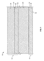
- Fig. 1 shows a partial cross-section of a turbine engine component 5 having a TBC system (coating system) 10 in accordance with the present disclosure.
- the turbine engine component 5 includes a substrate 20 upon which the coating system 10 is deposited.
- the substrate 20 includes a first surface 22 and an opposing second surface 24.
- the first surface 22 is a hot side surface, or in other words, the surface facing the hot operational temperatures of the component 5.
- the first surface 22 may be facing the flow of hot turbine gases.
- the second side surface 24 is a cold side surface, or in other words, the surface facing away from the hot operational temperatures of the component 5.
- the second side surface 24 may be facing a cooling gas.
- the first surface 22 and the second surface 24 are parallel, however, in alternative arrangements, the substrate 20 may includes surfaces of any arrangement in conformance of the engine component 5.
- the substrate 20 is formed of any operable material.
- the substrate 20 may be formed of any of a variety of metals or metal alloys, including those based on nickel, cobalt and/or iron alloys or superalloys.
- substrate 20 is made of a nickel-base alloy, and in another embodiment substrate 20 is made of a nickel-base superalloy.
- a nickel-base superalloy may be strengthened by the precipitation of gamma prime or a related phase.
- the nickel-base superalloy has a composition, in weight percent, of from about 4 to about 20 percent cobalt, from about 1 to about 10 percent chromium, from about 5 to about 7 percent aluminum, from about 0 to about 2 percent molybdenum, from about 3 to about 8 percent tungsten, from about 4 to about 12 percent tantalum, from about 0 to about 2 percent titanium, from about 0 to about 8 percent rhenium, from about 0 to about 6 percent ruthenium, from about 0 to about 1 percent niobium, from about 0 to about 0.1 percent carbon, from about 0 to about 0.01 percent boron, from about 0 to about 0.1 percent yttrium , from about 0 to about 1.5 percent hafnium, balance nickel and incidental impurities.
- a suitable nickel-base superalloy is available by the trade name Rene N5, which has a nominal composition by weight of 7.5% cobalt, 7% chromium, 1.5% molybdenum, 6.5% tantalum, 6.2% aluminum, 5% tungsten, 3% rhenium, 0.15% hafnium, 0.004% boron, and 0.05% carbon, and the balance nickel and minor impurities.
- the coating system 10 includes a bond coat 30 over and in contact with the first side surface 22 and a metallic layer 32 over and in contact with the second side surface 24.
- the coating system 10 further includes a ceramic layer coating the first bond coat 30.
- the bond coat 30 and the metallic layer 32 may be a metal, metallic, intermetallic, metal alloy, composite and combinations thereof.
- the bond coat 30 and the metallic layer 32 may have the same or different compositions.
- the bond coat 30 and the metallic layer 32 may be a NiAl.
- the bond coat 30 is a NiAl, such as a predominantly beta NiAl phase, with limited alloying additions.
- the NiAl coating may have an aluminum content of from about 9 to about 12 weight percent, balance essentially nickel, and in another embodiment, have an aluminum content from about 18 to about 21 weight percent aluminum, balance essentially nickel.
- the bulk of the bond coating can consist of a dense layer of NiAl formed using a deposition process such as an air plasma spraying (APS), a wire arc spraying, a high velocity oxy fuel (HVOF) spray, and a low pressure plasma spray (LPPS) process.
- the composition of the bond coat is not limited to NiAl bond coatings, and may be any metallic coating with an appropriate bonding and temperature capability.
- the bond coat 30 may be a NiCrAlY coating.
- the bond coat 30 may have a thickness of about 100 to about 300 microns. The thickness of the bond coating can vary depending on the component and operational environment.
- the metallic layer 32 is a high thermal conductivity metallic.
- the metallic layer 32 has a thermal conductivity of between about 20 and about 60 BTU/hr ft °F.
- the metallic layer 32 has a high thermal conductivity of between about 30 and about 45 BTU/hrft°F.
- the metallic layer 32 has a thermal conductivity of between about 38 and about 42 BTU/hr ft °F.
- the metallic layer 32 may be a NiAl coating having a high thermal conductivity.
- the metallic layer 32 may be a NiAl having an aluminum content of greater than about 50 weight percent.
- the metallic layer 32 is deposited by a deposition method, such as by an air plasma spraying (APS), a wire arc spraying, a high velocity oxy fuel (HVOF) spray, and a low pressure plasma spray (LPPS) process.
- APS air plasma spraying
- HVOF high velocity oxy fuel
- LPPS low pressure plasma spray
- the metallic layer 32 may have a thickness of from about 50 to about 600 microns, and more preferred from about 200 to about 400 microns. The thickness of the metallic layer 32 can vary depending on the component and operational environment.
- a metallic layer 32 of a NiAl may be appreciated by a comparison of the thermal conductivities of air plasma spray (APS) NiAl and NiCrAlY coatings as shown in Fig. 2 .
- APS NiAl coatings have a high thermal conductivity over the temperature range of operation of turbine components, which increases heat transfer from the substrate 20.
- a low thermal conductivity metallic bond coat may be used as the first bond coat 30, and a high thermal conductivity metallic layer may be used as the metallic layer 32.
- the first bond coat 30 may be a NiCrAlY bond coat
- the metallic layer 32 may be a NiAl bond coat having a high thermal conductivity.
- the ceramic layer 34 may be a low thermal conductivity ceramic.
- the low thermal conductivity ceramic may have a thermal conductivity of about 0.1 to 1.0 BTU/ft hr °F, preferably in the range of 0.3 to 0.6 BTU/ft hr °F.
- the low thermal conductivity ceramic may be a mixture of zirconiun oxide, yttrium oxide, ytterbium oxide and nyodenium oxide.
- the low thermal conductivity ceramic may be an yttria-stablilized zirconia (YSZ).
- the ceramic layer 34 may be an YSZ having a composition of about 3 to about 10 weight percent yttria.
- the ceramic layer 34 may be another ceramic material, such as yttria, nonstablilized zirconia, or zirconia stabilized by other oxides, such as magnesia (MgO), ceria (CeO 2 ), scandia (Sc 2 O 3 ) or alumina (Al 2 O 3 ).
- the ceramic layer 34 may include one or more rare earth oxides such as, but not limited to, ytterbia, scandia, lanthanum oxide, neodymia, erbia and combinations thereof. In these yet other embodiments, the rare earth oxides may replace a portion or all of the yttria in the stabilized zirconia system.
- the ceramic layer 34 is deposited to a thickness that is sufficient to provide the required thermal protection for the underlying substrate, generally on the order of from about 75 to about 350 microns.
- the first bond coat 30 includes an oxide surface layer (scale) 31 to which the ceramic layer 34 chemically bonds.
- the metallic layer 32 has an outer surface 36.
- the outer surface 36 may be exposed to temperatures less than the temperatures to which the ceramic layer 34 is exposed.
- the outer surface 36 is roughened between about 300 and 900 micro-inches to increase heat transfer.
- the outer surface 36 is roughened between about 500 and 700 micro-inches.
- the roughness of the outer surface 36 may be formed during depositing of the metallic layer 32, and may be controlled by controlling deposition process parameters including, but not limited to, particle size and spray velocity.
- the roughening may be in the form of dimples and/or grooves.
- the outer surface 36 may be roughed and/or additionally roughened after the deposition of the metallic layer 32 by, for example, a mechanical or chemical roughening process.
- the metallic layer 32 is not present and the outer surface 36 is the second side surface 24 of the substrate 20.
- the substrate 20 may be formed of a high thermal conductivity metallic composition.
- the substrate 20 may be a high thermal conductivity metal, metallic, intermetallic, metal alloy, composite and combinations thereof.
- the substrate may have a thermal conductivity of between about 20 and about 60 BTU/hr ft °F. In another embodiment, the substrate 20 has a high thermal conductivity of between about 30 and about 45 BTU/hrft°F. In yet still another embodiment, the substrate 20 has a thermal conductivity of between about 38 and about 42 BTU/hr ft °F. In one embodiment, the substrate 20 may be a NiAl having a high thermal conductivity. For example, the substrate 20 may be formed of a NiAl having an aluminum content of greater than about 50 weight percent aluminum. Further, the outer surface 36 may be roughened to increase heat transfer. In one embodiment, the outer surface 36 is roughened between about 300 and 900 micro-inches to increase heat transfer.
- the outer surface 36 is roughened between about 500 and 700 micro-inches.
- the roughness of the outer surface 36 may be formed during the forming of the substrate 20.
- the roughness of the outer surface 36 may be formed during casting of the substrate 20.
- the roughening may be in the form of dimples and/or grooves.
- the outer surface 36 may be roughed or additionally roughened after the deposition of the second bond coat 32 by, for example, a mechanical or chemical roughening process
Landscapes
- Chemical & Material Sciences (AREA)
- Engineering & Computer Science (AREA)
- Mechanical Engineering (AREA)
- Materials Engineering (AREA)
- Inorganic Chemistry (AREA)
- Metallurgy (AREA)
- Chemical Kinetics & Catalysis (AREA)
- Organic Chemistry (AREA)
- General Engineering & Computer Science (AREA)
- Ceramic Engineering (AREA)
- Physics & Mathematics (AREA)
- Plasma & Fusion (AREA)
- Turbine Rotor Nozzle Sealing (AREA)
- Other Surface Treatments For Metallic Materials (AREA)
- Coating By Spraying Or Casting (AREA)
Abstract
Description
- The present disclosure is directed to a method and apparatus for improving the operation of turbine engine components. In particular, the present disclosure relates to turbine engine components having coatings that enhance the heat transfer.
- The efficiency of turbine engines, for example gas turbines, is increased as the firing temperature, otherwise known as the working temperature, of the turbine increases. This increase in temperature results in at least some increase in power with the use of the same, if not less, fuel. Thus it is desirable to raise the firing temperature of a turbine to increase the efficiency.
- However, as the firing temperature of gas turbines rises, the metal temperature of the combustion components, including but not limited to combustion liners and transition pieces otherwise know as ducts, increases. A combustion liner is incorporated into a turbine, and defines, in part with a transition piece or duct, an area for a flame to bum fuel. These components, as well as other components in the gas path environment, are subject to significant temperature extremes and degradation by oxidizing and corrosive environments.
- Turbine combustion components, such as but not limited to, combustion liners, ducts, combustor deflectors, combustor centerbodies, nozzles and other structural hardware are often formed of heat resistant materials. The heat resistant materials are often coated with other heat resistant materials. For example, turbine components may be formed of wrought superalloys, such as but not limited to Hasteloy alloys, Nimonic alloys, Inconel alloys, and other similar alloys. These superalloys do not possess a desirable oxidation resistance at high temperatures, for example at temperatures greater than about 1500°F. Therefore, to reduce the turbine component temperatures and to provide oxidation and corrosion protection against hot combustion gases, a heat resistant coating, such as but not limited to, a bond coating and a thermal barrier coating (TBC) are often applied to a surface of the turbine component exposed to the hot combustion gases, or otherwise known as a hot side surface. For example, a turbine component may include a thermally sprayed MCrAIY overlay coating as a bond coat and an air plasma sprayed (APS) zirconia-based ceramic as an insulating TBC. Often, the TBC is a zirconia stabilized with yttria ceramic.
- Recently, ceramic top coat compositions with low thermal conductivity have increased temperature operation and strained the capability of applying only a thermal barrier coating to the hot side of turbine components. Current TBC systems have performed well in service in certain applications, however, improved coatings are sought to achieve greater temperature-thermal cycler time capability for longer service intervals or temperature capability.
- What is needed is a coating system that enhances heat transfer from turbine components allowing turbine components to operate at higher system temperatures.
- In an exemplary embodiment, a turbine combustion component is disclosed that includes a substrate having a hot side surface and a cold side surface, and an outside surface having a high thermal conductivity. The outside surface is either the cold side surface or a surface of a second bond coat.
- In another exemplary embodiment, a thermal barrier coating system for a substrate is disclosed that includes a first bond coat deposited on and in contact with a hot side surface of the substrate, a ceramic layer deposited on and in contact with the first bond coat, and an outside surface having a high thermal conductivity. The outside surface is either the cold side surface of the substrate or a surface of a second bond coat.
- In another exemplary embodiment, a process of improving the heat transfer of a component is disclosed that includes providing a substrate having a first surface and a second surface, depositing a first bond coat on and in contact with the first surface, depositing a ceramic layer on and in contact with the first bond coat, and providing an outside surface having a high thermal conductivity. The outside surface is either the second surface or a surface of a second bond coat.
- One advantage of the present disclosure includes the reduction of bond coat temperature.
- Another advantage of the present disclosure includes increased component life.
- Another advantage of the present disclosure is operating with lower flow of cooling air thereby improving engine efficiency.
- Another advantage of the present disclosure is operating the TBC surface at a higher temperature thereby improving engine efficiency.
- Another advantage of the present disclosure is the use of a lighter bond coating.
- Other features and advantages of the present disclosure will be apparent from the following more detailed description of the preferred embodiment, taken in conjunction with the accompanying drawings which illustrate, by way of example, the principles of the disclosure.
-
-
Fig. 1 shows a schematic view of a thermal barrier coating system having a bond coat in accordance with one exemplary embodiment according to the disclosure. -
Fig. 2 shows a comparison of thermal conductivity for NiAl and NiCrAlY coatings. - Wherever possible, the same reference numbers will be used throughout the drawings to represent the same parts.
- In one embodiment, the present disclosure is generally applicable to metal components that are protected from a thermally hostile environment by a thermal barrier coating (TBC) system. Notable examples of such components include the high and low pressure turbine nozzles (vanes), shrouds, combustor liners, transition pieces, turbine frame and augmentor hardware of gas turbine engines. While this disclosure is particularly applicable to turbine engine components, the teachings of this disclosure are generally applicable to any component on which a thermal barrier may be used to thermally insulate the component from its environment.
-
Fig. 1 shows a partial cross-section of aturbine engine component 5 having a TBC system (coating system) 10 in accordance with the present disclosure. Theturbine engine component 5 includes asubstrate 20 upon which thecoating system 10 is deposited. Thesubstrate 20 includes afirst surface 22 and an opposingsecond surface 24. Thefirst surface 22 is a hot side surface, or in other words, the surface facing the hot operational temperatures of thecomponent 5. For example, thefirst surface 22 may be facing the flow of hot turbine gases. Thesecond side surface 24 is a cold side surface, or in other words, the surface facing away from the hot operational temperatures of thecomponent 5. Thesecond side surface 24 may be facing a cooling gas. In the cross-section shown inFig. 1 , thefirst surface 22 and thesecond surface 24 are parallel, however, in alternative arrangements, thesubstrate 20 may includes surfaces of any arrangement in conformance of theengine component 5. - In one embodiment, the
substrate 20 is formed of any operable material. For example, thesubstrate 20 may be formed of any of a variety of metals or metal alloys, including those based on nickel, cobalt and/or iron alloys or superalloys. In one embodiment,substrate 20 is made of a nickel-base alloy, and in anotherembodiment substrate 20 is made of a nickel-base superalloy. A nickel-base superalloy may be strengthened by the precipitation of gamma prime or a related phase. In one example, the nickel-base superalloy has a composition, in weight percent, of from about 4 to about 20 percent cobalt, from about 1 to about 10 percent chromium, from about 5 to about 7 percent aluminum, from about 0 to about 2 percent molybdenum, from about 3 to about 8 percent tungsten, from about 4 to about 12 percent tantalum, from about 0 to about 2 percent titanium, from about 0 to about 8 percent rhenium, from about 0 to about 6 percent ruthenium, from about 0 to about 1 percent niobium, from about 0 to about 0.1 percent carbon, from about 0 to about 0.01 percent boron, from about 0 to about 0.1 percent yttrium , from about 0 to about 1.5 percent hafnium, balance nickel and incidental impurities. For example, a suitable nickel-base superalloy is available by the trade name Rene N5, which has a nominal composition by weight of 7.5% cobalt, 7% chromium, 1.5% molybdenum, 6.5% tantalum, 6.2% aluminum, 5% tungsten, 3% rhenium, 0.15% hafnium, 0.004% boron, and 0.05% carbon, and the balance nickel and minor impurities. - In accordance with one embodiment of the present disclosure, the
coating system 10 includes abond coat 30 over and in contact with thefirst side surface 22 and ametallic layer 32 over and in contact with thesecond side surface 24. Thecoating system 10 further includes a ceramic layer coating thefirst bond coat 30. - In one embodiment, the
bond coat 30 and themetallic layer 32 may be a metal, metallic, intermetallic, metal alloy, composite and combinations thereof. Thebond coat 30 and themetallic layer 32 may have the same or different compositions. In one embodiment, thebond coat 30 and themetallic layer 32 may be a NiAl. In one embodiment, thebond coat 30 is a NiAl, such as a predominantly beta NiAl phase, with limited alloying additions. The NiAl coating may have an aluminum content of from about 9 to about 12 weight percent, balance essentially nickel, and in another embodiment, have an aluminum content from about 18 to about 21 weight percent aluminum, balance essentially nickel. The bulk of the bond coating can consist of a dense layer of NiAl formed using a deposition process such as an air plasma spraying (APS), a wire arc spraying, a high velocity oxy fuel (HVOF) spray, and a low pressure plasma spray (LPPS) process. In one embodiment, the composition of the bond coat is not limited to NiAl bond coatings, and may be any metallic coating with an appropriate bonding and temperature capability. For example, thebond coat 30 may be a NiCrAlY coating. Thebond coat 30 may have a thickness of about 100 to about 300 microns. The thickness of the bond coating can vary depending on the component and operational environment. - According to the disclosure, the
metallic layer 32 is a high thermal conductivity metallic. In one embodiment, themetallic layer 32 has a thermal conductivity of between about 20 and about 60 BTU/hr ft °F. In another embodiment, themetallic layer 32 has a high thermal conductivity of between about 30 and about 45 BTU/hrft°F. In yet still another embodiment, themetallic layer 32 has a thermal conductivity of between about 38 and about 42 BTU/hr ft °F. In one embodiment, themetallic layer 32 may be a NiAl coating having a high thermal conductivity. For example, themetallic layer 32 may be a NiAl having an aluminum content of greater than about 50 weight percent. In one embodiment, themetallic layer 32 is deposited by a deposition method, such as by an air plasma spraying (APS), a wire arc spraying, a high velocity oxy fuel (HVOF) spray, and a low pressure plasma spray (LPPS) process. In one embodiment, themetallic layer 32 may have a thickness of from about 50 to about 600 microns, and more preferred from about 200 to about 400 microns. The thickness of themetallic layer 32 can vary depending on the component and operational environment. - The benefit of using a
metallic layer 32 of a NiAl may be appreciated by a comparison of the thermal conductivities of air plasma spray (APS) NiAl and NiCrAlY coatings as shown inFig. 2 . As can be seen inFig. 2 , APS NiAl coatings have a high thermal conductivity over the temperature range of operation of turbine components, which increases heat transfer from thesubstrate 20. - In one embodiment, a low thermal conductivity metallic bond coat may be used as the
first bond coat 30, and a high thermal conductivity metallic layer may be used as themetallic layer 32. For example, in one embodiment, thefirst bond coat 30 may be a NiCrAlY bond coat, and themetallic layer 32 may be a NiAl bond coat having a high thermal conductivity. - In one embodiment, the ceramic layer 34 may be a low thermal conductivity ceramic. For example, the low thermal conductivity ceramic may have a thermal conductivity of about 0.1 to 1.0 BTU/ft hr °F, preferably in the range of 0.3 to 0.6 BTU/ft hr °F. In one embodiment, the low thermal conductivity ceramic may be a mixture of zirconiun oxide, yttrium oxide, ytterbium oxide and nyodenium oxide. In another embodiment, the low thermal conductivity ceramic may be an yttria-stablilized zirconia (YSZ). In one embodiment, the ceramic layer 34 may be an YSZ having a composition of about 3 to about 10 weight percent yttria. In another embodiment, the ceramic layer 34 may be another ceramic material, such as yttria, nonstablilized zirconia, or zirconia stabilized by other oxides, such as magnesia (MgO), ceria (CeO2), scandia (Sc2O3) or alumina (Al2O3). In yet other embodiments, the ceramic layer 34 may include one or more rare earth oxides such as, but not limited to, ytterbia, scandia, lanthanum oxide, neodymia, erbia and combinations thereof. In these yet other embodiments, the rare earth oxides may replace a portion or all of the yttria in the stabilized zirconia system. The ceramic layer 34 is deposited to a thickness that is sufficient to provide the required thermal protection for the underlying substrate, generally on the order of from about 75 to about 350 microns. As with prior art bond coatings, the
first bond coat 30 includes an oxide surface layer (scale) 31 to which the ceramic layer 34 chemically bonds. - Referring again to
Fig. 1 , themetallic layer 32 has anouter surface 36. Theouter surface 36 may be exposed to temperatures less than the temperatures to which the ceramic layer 34 is exposed. In one embodiment, theouter surface 36 is roughened between about 300 and 900 micro-inches to increase heat transfer. In another embodiment, theouter surface 36 is roughened between about 500 and 700 micro-inches. The roughness of theouter surface 36 may be formed during depositing of themetallic layer 32, and may be controlled by controlling deposition process parameters including, but not limited to, particle size and spray velocity. The roughening may be in the form of dimples and/or grooves. In another embodiment, theouter surface 36 may be roughed and/or additionally roughened after the deposition of themetallic layer 32 by, for example, a mechanical or chemical roughening process. - In another exemplary embodiment, the
metallic layer 32 is not present and theouter surface 36 is thesecond side surface 24 of thesubstrate 20. In this embodiment, thesubstrate 20 may be formed of a high thermal conductivity metallic composition. In one embodiment, thesubstrate 20 may be a high thermal conductivity metal, metallic, intermetallic, metal alloy, composite and combinations thereof. - In one embodiment, the substrate may have a thermal conductivity of between about 20 and about 60 BTU/hr ft °F. In another embodiment, the
substrate 20 has a high thermal conductivity of between about 30 and about 45 BTU/hrft°F. In yet still another embodiment, thesubstrate 20 has a thermal conductivity of between about 38 and about 42 BTU/hr ft °F. In one embodiment, thesubstrate 20 may be a NiAl having a high thermal conductivity. For example, thesubstrate 20 may be formed of a NiAl having an aluminum content of greater than about 50 weight percent aluminum. Further, theouter surface 36 may be roughened to increase heat transfer. In one embodiment, theouter surface 36 is roughened between about 300 and 900 micro-inches to increase heat transfer. In another embodiment, theouter surface 36 is roughened between about 500 and 700 micro-inches. The roughness of theouter surface 36 may be formed during the forming of thesubstrate 20. For example, the roughness of theouter surface 36 may be formed during casting of thesubstrate 20. The roughening may be in the form of dimples and/or grooves. In another embodiment, theouter surface 36 may be roughed or additionally roughened after the deposition of thesecond bond coat 32 by, for example, a mechanical or chemical roughening process - While the disclosure has been described with reference to a preferred embodiment, it will be understood by those skilled in the art that various changes may be made and equivalents may be substituted for elements thereof without departing from the scope of the disclosure. In addition, many modifications may be made to adapt a particular situation or material to the teachings of the disclosure without departing from the essential scope thereof. Therefore, it is intended that the disclosure not be limited to the particular embodiment disclosed as the best mode contemplated for carrying out this disclosure, but that the disclosure will include all embodiments falling within the scope of the appended claims.
- For completeness, various aspects of the invention are now set out in the following numbered clauses:
- 1. A turbine combustion component, comprising:
- a substrate having a hot side surface and a cold side surface; and
- an outside surface having a high thermal conductivity;
- wherein the outside surface is either the cold side surface or a surface of a metallic layer.
- 2. The component of clause 1, wherein the high thermal conductivity is between about 20 and about 60 BTU/hr ft °F.
- 3. The component of clause 1 or clause 2, wherein the outside surface has a roughness of between about 300 and about 900 micro-inches.
- 4. The component of any preceding clause, wherein the substrate is a NiAl having a high thermal conductivity.
- 5. The component of any preceding clause, further comprising a bond coat deposited on and in contact with the hot side surface and a ceramic layer deposited on and in contact with the bond coat.
- 6. The component of any preceding clause, wherein the cold side surface is the outside surface.
- 7. The component of any preceding clause, wherein the component further comprises:
- a bond coat deposited on and in contact with the hot side surface; and
- a ceramic layer deposited on and in contact with the bond coat;
- wherein the outside surface is a surface of a metallic layer deposited on and in contact with the cold side surface.
- 8. The component of any preceding clause, wherein the metallic layer is a NiAl comprising greater than about 50 weight percent aluminum.
- 9. The component of any preceding clause, wherein the metallic layer has a thickness of between about 50 µm and about 600 µm.
- 10. A thermal barrier coating system for a substrate, comprising:
- a bond coat deposited on and in contact with a hot side surface of the substrate;
- a ceramic layer deposited on and in contact with the bond coat; and
- an outside surface having a high thermal conductivity;
- wherein the outside surface is either the cold side surface of the substrate or a surface of a metallic layer.
- 11. The system of any preceding clause, wherein the high thermal conductivity is between about 20 and about 60 BTU/hr ft °F.
- 12. The system of any preceding clause, wherein the outside surface has a roughness of between about 300 and about 900 micro-inches.
- 13. The system of any preceding clause, wherein the outside surface is the cold side surface of the substrate, wherein the substrate is a NiAl having a high thermal conductivity
- 14. The system of any preceding clause, wherein outside surface is a surface of a metallic layer, wherein the metallic layer is a NiAl comprising greater than about 50 weight percent aluminum.
- 15. The system of any preceding clause, wherein the metallic layer has a thickness of about 50 µm to about 600 µm.
- 16. A method of improving the heat transfer of a component, comprising:
- providing a substrate having a first surface and a second surface;
- depositing a bond coat on and in contact with the first surface;
- depositing a ceramic layer on and in contact with the bond coat; and
- providing an outside surface having a high thermal conductivity;
- wherein the outside surface is either the second surface or a surface of a metallic layer.
- 17. The method of any preceding clause, wherein the high thermal conductivity is between about 20 and about 60 BTU/hr ft °F.
- 18. The method of any preceding clause, further comprising:
- roughening the outside surface to between about 300 and about 900 micro-inches.
- 19. The method of clause 16, wherein the outside surface is the second surface, and the substrate is a NiAl having a high thermal conductivity.
- 20. The method of clause 16, wherein the outside surface is a surface of a high conductivity metallic layer deposited on and in contact with the second surface, the metallic layer including the outside surface.
Claims (15)
- A turbine combustion component (5), comprising:a substrate (2) having a hot side surface (22) and a cold side surface (24); andan outside surface having a high thermal conductivity;wherein the outside surface is either the cold side surface (24) or a surface of a metallic layer (32).
- The component (5) of claim 1, wherein the high thermal conductivity is between about 20 and about 60 BTU/hr ft °F.
- The component (5) of claim 1 or claim 2, wherein the outside surface has a roughness of between about 300 and about 900 micro-inches.
- The component (5) of any preceding claim, wherein the substrate (20) is a NiAl having a high thermal conductivity.
- The component (5) of any preceding claim, further comprising a bond coat (30) deposited on and in contact with the hot side surface (22) and a ceramic layer (34) deposited on and in contact with the bond coat (30).
- The component (5) of any preceding claim, wherein the cold side surface (24) is the outside surface.
- The component (5) of any preceding claim, wherein the component (5) further comprises:a bond coat (30) deposited on and in contact with the hot side surface (22); anda ceramic layer (34) deposited on and in contact with the bond coat (30);wherein the outside surface is a surface of a metallic layer (32) deposited on andin contact with the cold side surface (24).
- The component (5) of claim 7, wherein the metallic layer (32) is a NiAl comprising greater than about 50 weight percent aluminum.
- The component (5) of claim 7 or claim 8, wherein the metallic layer (32) has a thickness of between about 50 µm and about 600 µm.
- A thermal barrier coating system for a substrate, comprising:a bond coat deposited on and in contact with a hot side surface of the substrate;a ceramic layer deposited on and in contact with the bond coat; andan outside surface having a high thermal conductivity;wherein the outside surface is either the cold side surface of the substrate or a surface of a metallic layer.
- The system of claim 10, wherein the high thermal conductivity is between about 20 and about 60 BTU/hr ft °F.
- The system of claim 10 or claim 11, wherein the outside surface has a roughness of between about 300 and about 900 micro-inches.
- The system of any one of claims 10 to 12, wherein the outside surface is the cold side surface of the substrate, wherein the substrate is a NiAl having a high thermal conductivity
- The system of any one of claims 10 to 13, wherein outside surface is a surface of a metallic layer, wherein the metallic layer is a NiAl comprising greater than about 50 weight percent aluminum.
- The system of claim 14, wherein the metallic layer has a thickness of about 50 µm to about 600 µm.
Applications Claiming Priority (1)
| Application Number | Priority Date | Filing Date | Title |
|---|---|---|---|
| US12/347,676 US8722202B2 (en) | 2008-12-31 | 2008-12-31 | Method and system for enhancing heat transfer of turbine engine components |
Publications (2)
| Publication Number | Publication Date |
|---|---|
| EP2204540A2 true EP2204540A2 (en) | 2010-07-07 |
| EP2204540A3 EP2204540A3 (en) | 2013-02-13 |
Family
ID=42041789
Family Applications (1)
| Application Number | Title | Priority Date | Filing Date |
|---|---|---|---|
| EP09179370A Ceased EP2204540A3 (en) | 2008-12-31 | 2009-12-16 | A thermal barrier coating system for enhancing heat transfer of turbine engine components |
Country Status (4)
| Country | Link |
|---|---|
| US (1) | US8722202B2 (en) |
| EP (1) | EP2204540A3 (en) |
| JP (1) | JP5815920B2 (en) |
| CN (1) | CN101793195B (en) |
Families Citing this family (11)
| Publication number | Priority date | Publication date | Assignee | Title |
|---|---|---|---|---|
| US9950382B2 (en) * | 2012-03-23 | 2018-04-24 | Pratt & Whitney Canada Corp. | Method for a fabricated heat shield with rails and studs mounted on the cold side of a combustor heat shield |
| US20140174091A1 (en) * | 2012-12-21 | 2014-06-26 | United Technologies Corporation | Repair procedure for a gas turbine engine via variable polarity welding |
| JP6470135B2 (en) | 2014-07-14 | 2019-02-13 | ユナイテッド テクノロジーズ コーポレイションUnited Technologies Corporation | Additional manufactured surface finish |
| US10132498B2 (en) * | 2015-01-20 | 2018-11-20 | United Technologies Corporation | Thermal barrier coating of a combustor dilution hole |
| US10386067B2 (en) * | 2016-09-15 | 2019-08-20 | United Technologies Corporation | Wall panel assembly for a gas turbine engine |
| US11773734B2 (en) * | 2017-09-07 | 2023-10-03 | General Electric Company | Liquid bond coatings for barrier coatings |
| US11098899B2 (en) | 2018-01-18 | 2021-08-24 | Raytheon Technologies Corporation | Panel burn through tolerant shell design |
| DE102018204498A1 (en) * | 2018-03-23 | 2019-09-26 | Siemens Aktiengesellschaft | Ceramic material based on zirconium oxide with other oxides |
| DE102018215223A1 (en) * | 2018-09-07 | 2020-03-12 | Siemens Aktiengesellschaft | Ceramic material based on zirconium oxide with additional oxides and layer system |
| GB202213805D0 (en) * | 2022-09-22 | 2022-11-09 | Rolls Royce Plc | Platform for stator vane |
| GB202213804D0 (en) | 2022-09-22 | 2022-11-09 | Rolls Royce Plc | Platform for stator vane |
Citations (6)
| Publication number | Priority date | Publication date | Assignee | Title |
|---|---|---|---|---|
| US5975852A (en) | 1997-03-31 | 1999-11-02 | General Electric Company | Thermal barrier coating system and method therefor |
| US6461746B1 (en) | 2000-04-24 | 2002-10-08 | General Electric Company | Nickel-base superalloy article with rhenium-containing protective layer, and its preparation |
| US6546730B2 (en) | 2001-02-14 | 2003-04-15 | General Electric Company | Method and apparatus for enhancing heat transfer in a combustor liner for a gas turbine |
| US20040166355A1 (en) | 2003-02-24 | 2004-08-26 | General Electric Company | Coating and coating process incorporating raised surface features for an air-cooled surface |
| US20050191516A1 (en) | 2003-04-30 | 2005-09-01 | Nagaraj Bangalore A. | Method for applying or repairing thermal barrier coatings |
| EP1600518A2 (en) | 2004-05-27 | 2005-11-30 | General Electric Company | Nickel aluminide coating with improved oxide stability |
Family Cites Families (12)
| Publication number | Priority date | Publication date | Assignee | Title |
|---|---|---|---|---|
| US5348446A (en) * | 1993-04-28 | 1994-09-20 | General Electric Company | Bimetallic turbine airfoil |
| US6465090B1 (en) | 1995-11-30 | 2002-10-15 | General Electric Company | Protective coating for thermal barrier coatings and coating method therefor |
| US6393828B1 (en) | 1997-07-21 | 2002-05-28 | General Electric Company | Protective coatings for turbine combustion components |
| EP0933797B1 (en) | 1998-01-30 | 2004-07-28 | Hitachi, Ltd. | Cathode ray tube |
| US6403165B1 (en) * | 2000-02-09 | 2002-06-11 | General Electric Company | Method for modifying stoichiometric NiAl coatings applied to turbine airfoils by thermal processes |
| US6607789B1 (en) | 2001-04-26 | 2003-08-19 | General Electric Company | Plasma sprayed thermal bond coat system |
| US6730179B2 (en) * | 2001-08-31 | 2004-05-04 | Sermatech International Inc. | Method for producing local aluminide coating |
| US7226672B2 (en) | 2002-08-21 | 2007-06-05 | United Technologies Corporation | Turbine components with thermal barrier coatings |
| JP4907072B2 (en) | 2003-10-15 | 2012-03-28 | ゼネラル・エレクトリック・カンパニイ | Selective area vapor phase aluminization method |
| US7386980B2 (en) * | 2005-02-02 | 2008-06-17 | Power Systems Mfg., Llc | Combustion liner with enhanced heat transfer |
| US20070160859A1 (en) | 2006-01-06 | 2007-07-12 | General Electric Company | Layered thermal barrier coatings containing lanthanide series oxides for improved resistance to CMAS degradation |
| US20070207339A1 (en) | 2006-03-06 | 2007-09-06 | Zimmerman Robert G Jr | Bond coat process for thermal barrier coating |
-
2008
- 2008-12-31 US US12/347,676 patent/US8722202B2/en active Active
-
2009
- 2009-12-16 EP EP09179370A patent/EP2204540A3/en not_active Ceased
- 2009-12-25 JP JP2009293580A patent/JP5815920B2/en not_active Expired - Fee Related
- 2009-12-31 CN CN200910266855.8A patent/CN101793195B/en active Active
Patent Citations (6)
| Publication number | Priority date | Publication date | Assignee | Title |
|---|---|---|---|---|
| US5975852A (en) | 1997-03-31 | 1999-11-02 | General Electric Company | Thermal barrier coating system and method therefor |
| US6461746B1 (en) | 2000-04-24 | 2002-10-08 | General Electric Company | Nickel-base superalloy article with rhenium-containing protective layer, and its preparation |
| US6546730B2 (en) | 2001-02-14 | 2003-04-15 | General Electric Company | Method and apparatus for enhancing heat transfer in a combustor liner for a gas turbine |
| US20040166355A1 (en) | 2003-02-24 | 2004-08-26 | General Electric Company | Coating and coating process incorporating raised surface features for an air-cooled surface |
| US20050191516A1 (en) | 2003-04-30 | 2005-09-01 | Nagaraj Bangalore A. | Method for applying or repairing thermal barrier coatings |
| EP1600518A2 (en) | 2004-05-27 | 2005-11-30 | General Electric Company | Nickel aluminide coating with improved oxide stability |
Also Published As
| Publication number | Publication date |
|---|---|
| JP5815920B2 (en) | 2015-11-17 |
| CN101793195A (en) | 2010-08-04 |
| US8722202B2 (en) | 2014-05-13 |
| JP2010156327A (en) | 2010-07-15 |
| US20100162715A1 (en) | 2010-07-01 |
| CN101793195B (en) | 2015-04-08 |
| EP2204540A3 (en) | 2013-02-13 |
Similar Documents
| Publication | Publication Date | Title |
|---|---|---|
| US8722202B2 (en) | Method and system for enhancing heat transfer of turbine engine components | |
| EP1591550B1 (en) | Thermal barrier coating having an interfacial layer for spallation life enhancement and low conductivity | |
| US5981088A (en) | Thermal barrier coating system | |
| US6730413B2 (en) | Thermal barrier coating | |
| US5780110A (en) | Method for manufacturing thermal barrier coated articles | |
| US7291403B2 (en) | Thermal barrier coating system | |
| EP2607510B1 (en) | Nickel-cobalt-based alloy and bond coat and bond coated articles incorporating the same | |
| US20080107920A1 (en) | Thermal barrier coated articles and methods of making the same | |
| EP1340833B1 (en) | Hybrid thermal barrier coating and method of making the same | |
| US20110151132A1 (en) | Methods for Coating Articles Exposed to Hot and Harsh Environments | |
| EP4353701A2 (en) | Gas turbine engine component coating with self-healing barrier layer | |
| US20100297410A1 (en) | Ceramic powder, ceramic layer and layer system of two pyrochlore phases and oxides | |
| US20120003460A1 (en) | Two-Layer Porous Layer System Having a Pyrochlore Phase | |
| WO2014113123A2 (en) | Spallation-resistant thermal barrier coating | |
| Grant | Thermal barrier coatings | |
| EP0987345B1 (en) | Thermal barrier coating system | |
| EP1729959A2 (en) | Durable thermal barrier coating having low thermal conductivity |
Legal Events
| Date | Code | Title | Description |
|---|---|---|---|
| PUAI | Public reference made under article 153(3) epc to a published international application that has entered the european phase |
Free format text: ORIGINAL CODE: 0009012 |
|
| AK | Designated contracting states |
Kind code of ref document: A2 Designated state(s): AT BE BG CH CY CZ DE DK EE ES FI FR GB GR HR HU IE IS IT LI LT LU LV MC MK MT NL NO PL PT RO SE SI SK SM TR |
|
| PUAL | Search report despatched |
Free format text: ORIGINAL CODE: 0009013 |
|
| AK | Designated contracting states |
Kind code of ref document: A3 Designated state(s): AT BE BG CH CY CZ DE DK EE ES FI FR GB GR HR HU IE IS IT LI LT LU LV MC MK MT NL NO PL PT RO SE SI SK SM TR |
|
| RIC1 | Information provided on ipc code assigned before grant |
Ipc: F01D 5/28 20060101AFI20130107BHEP Ipc: C23C 28/00 20060101ALI20130107BHEP |
|
| 17P | Request for examination filed |
Effective date: 20130813 |
|
| RBV | Designated contracting states (corrected) |
Designated state(s): AT BE BG CH CY CZ DE DK EE ES FI FR GB GR HR HU IE IS IT LI LT LU LV MC MK MT NL NO PL PT RO SE SI SK SM TR |
|
| 17Q | First examination report despatched |
Effective date: 20140211 |
|
| APBK | Appeal reference recorded |
Free format text: ORIGINAL CODE: EPIDOSNREFNE |
|
| APBN | Date of receipt of notice of appeal recorded |
Free format text: ORIGINAL CODE: EPIDOSNNOA2E |
|
| APBR | Date of receipt of statement of grounds of appeal recorded |
Free format text: ORIGINAL CODE: EPIDOSNNOA3E |
|
| APAF | Appeal reference modified |
Free format text: ORIGINAL CODE: EPIDOSCREFNE |
|
| APBT | Appeal procedure closed |
Free format text: ORIGINAL CODE: EPIDOSNNOA9E |
|
| STAA | Information on the status of an ep patent application or granted ep patent |
Free format text: STATUS: THE APPLICATION HAS BEEN REFUSED |
|
| 18R | Application refused |
Effective date: 20160520 |