EP2204238A1 - Process for manufacturing an integrated membrane of nozzles in mems technology for a spray device, and spray device using such membrane - Google Patents
Process for manufacturing an integrated membrane of nozzles in mems technology for a spray device, and spray device using such membrane Download PDFInfo
- Publication number
- EP2204238A1 EP2204238A1 EP09180395A EP09180395A EP2204238A1 EP 2204238 A1 EP2204238 A1 EP 2204238A1 EP 09180395 A EP09180395 A EP 09180395A EP 09180395 A EP09180395 A EP 09180395A EP 2204238 A1 EP2204238 A1 EP 2204238A1
- Authority
- EP
- European Patent Office
- Prior art keywords
- membrane
- nozzles
- forming
- substrate
- layer
- Prior art date
- Legal status (The legal status is an assumption and is not a legal conclusion. Google has not performed a legal analysis and makes no representation as to the accuracy of the status listed.)
- Granted
Links
Images


Classifications
-
- A—HUMAN NECESSITIES
- A61—MEDICAL OR VETERINARY SCIENCE; HYGIENE
- A61M—DEVICES FOR INTRODUCING MEDIA INTO, OR ONTO, THE BODY; DEVICES FOR TRANSDUCING BODY MEDIA OR FOR TAKING MEDIA FROM THE BODY; DEVICES FOR PRODUCING OR ENDING SLEEP OR STUPOR
- A61M15/00—Inhalators
- A61M15/009—Inhalators using medicine packages with incorporated spraying means, e.g. aerosol cans
-
- B—PERFORMING OPERATIONS; TRANSPORTING
- B05—SPRAYING OR ATOMISING IN GENERAL; APPLYING FLUENT MATERIALS TO SURFACES, IN GENERAL
- B05B—SPRAYING APPARATUS; ATOMISING APPARATUS; NOZZLES
- B05B1/00—Nozzles, spray heads or other outlets, with or without auxiliary devices such as valves, heating means
- B05B1/14—Nozzles, spray heads or other outlets, with or without auxiliary devices such as valves, heating means with multiple outlet openings; with strainers in or outside the outlet opening
-
- B—PERFORMING OPERATIONS; TRANSPORTING
- B05—SPRAYING OR ATOMISING IN GENERAL; APPLYING FLUENT MATERIALS TO SURFACES, IN GENERAL
- B05B—SPRAYING APPARATUS; ATOMISING APPARATUS; NOZZLES
- B05B17/00—Apparatus for spraying or atomising liquids or other fluent materials, not covered by the preceding groups
- B05B17/04—Apparatus for spraying or atomising liquids or other fluent materials, not covered by the preceding groups operating with special methods
- B05B17/06—Apparatus for spraying or atomising liquids or other fluent materials, not covered by the preceding groups operating with special methods using ultrasonic or other kinds of vibrations
- B05B17/0607—Apparatus for spraying or atomising liquids or other fluent materials, not covered by the preceding groups operating with special methods using ultrasonic or other kinds of vibrations generated by electrical means, e.g. piezoelectric transducers
- B05B17/0638—Apparatus for spraying or atomising liquids or other fluent materials, not covered by the preceding groups operating with special methods using ultrasonic or other kinds of vibrations generated by electrical means, e.g. piezoelectric transducers spray being produced by discharging the liquid or other fluent material through a plate comprising a plurality of orifices
-
- B—PERFORMING OPERATIONS; TRANSPORTING
- B05—SPRAYING OR ATOMISING IN GENERAL; APPLYING FLUENT MATERIALS TO SURFACES, IN GENERAL
- B05D—PROCESSES FOR APPLYING FLUENT MATERIALS TO SURFACES, IN GENERAL
- B05D7/00—Processes, other than flocking, specially adapted for applying liquids or other fluent materials to particular surfaces or for applying particular liquids or other fluent materials
-
- B—PERFORMING OPERATIONS; TRANSPORTING
- B81—MICROSTRUCTURAL TECHNOLOGY
- B81C—PROCESSES OR APPARATUS SPECIALLY ADAPTED FOR THE MANUFACTURE OR TREATMENT OF MICROSTRUCTURAL DEVICES OR SYSTEMS
- B81C1/00—Manufacture or treatment of devices or systems in or on a substrate
- B81C1/00015—Manufacture or treatment of devices or systems in or on a substrate for manufacturing microsystems
- B81C1/00023—Manufacture or treatment of devices or systems in or on a substrate for manufacturing microsystems without movable or flexible elements
- B81C1/00087—Holes
-
- B—PERFORMING OPERATIONS; TRANSPORTING
- B81—MICROSTRUCTURAL TECHNOLOGY
- B81B—MICROSTRUCTURAL DEVICES OR SYSTEMS, e.g. MICROMECHANICAL DEVICES
- B81B2201/00—Specific applications of microelectromechanical systems
- B81B2201/05—Microfluidics
- B81B2201/058—Microfluidics not provided for in B81B2201/051 - B81B2201/054
-
- B—PERFORMING OPERATIONS; TRANSPORTING
- B81—MICROSTRUCTURAL TECHNOLOGY
- B81B—MICROSTRUCTURAL DEVICES OR SYSTEMS, e.g. MICROMECHANICAL DEVICES
- B81B2203/00—Basic microelectromechanical structures
- B81B2203/01—Suspended structures, i.e. structures allowing a movement
- B81B2203/0127—Diaphragms, i.e. structures separating two media that can control the passage from one medium to another; Membranes, i.e. diaphragms with filtering function
-
- Y—GENERAL TAGGING OF NEW TECHNOLOGICAL DEVELOPMENTS; GENERAL TAGGING OF CROSS-SECTIONAL TECHNOLOGIES SPANNING OVER SEVERAL SECTIONS OF THE IPC; TECHNICAL SUBJECTS COVERED BY FORMER USPC CROSS-REFERENCE ART COLLECTIONS [XRACs] AND DIGESTS
- Y10—TECHNICAL SUBJECTS COVERED BY FORMER USPC
- Y10T—TECHNICAL SUBJECTS COVERED BY FORMER US CLASSIFICATION
- Y10T29/00—Metal working
- Y10T29/49—Method of mechanical manufacture
- Y10T29/49401—Fluid pattern dispersing device making, e.g., ink jet
Definitions
- the present invention relates to a process for manufacturing an integrated membrane of nozzles in MEMS technology for a spray device, and to the spray device that uses such membrane, in particular a spray or aerosol device of an inhaler used for administration of pharmaceutical products, parapharmaceutical products, or perfumes.
- inhalers of a known type are generally used for administering medicaments in controlled doses or for a wide range of aerosol-based therapies.
- An inhaler supplies the medicament, which is in liquid form, as a nebulized dispersion of drops.
- an inhaler is of contained dimensions and generally operated with a battery so that the patient is able to carry it with him and use it in a discrete way.
- Inhalers of a known type for example, of the type described in US 6,196,219 , generally comprise a membrane provided with nozzles (or pores) and set facing a reservoir containing the liquid to be nebulized.
- An actuation element for example, a piezoelectric actuation element, can be used for deforming the reservoir and causing exit of the liquid through the nozzles of the membrane.
- the effectiveness of a medical treatment depends upon the activity of the active principle, and said effectiveness depends in turn upon the amount of each dose of medicament nebulized and upon the point of impact of the spray. Consequently, the amount of nebulized liquid and the directionality of each spray should be as constant as possible for different sprays, so as to maximize the effectiveness of the medical therapy.
- the aim of the present invention is to provide a process for manufacturing an integrated membrane of nozzles obtained with MEMS technology for a spray device, and the spray device that uses said membrane that will be free from the drawbacks of the known art.
- Provided according to the present invention are a process for manufacturing an integrated membrane of nozzles obtained with MEMS technology for a spray device and the spray device that uses said membrane as defined in claim 1 and claim 11, respectively.
- a wafer 10 comprising a substrate 11 made, for example, of silicon of an N type having a thickness of between 400 ⁇ m and 725 ⁇ m, preferably 400 ⁇ m.
- a sacrificial layer 12 is then provided, made, for example, of silicon oxide, which has a thickness of between 0.6 ⁇ m and 1.5 ⁇ m, preferably 0.8 ⁇ m.
- the membrane layer 13 may be made of deposited material, compatible with silicon processing technology (e.g., deposited polysilicon).
- Providing a membrane layer 13 made of grown or deposited material has the advantage that the choice of the material to be used may be tuned according to the particular application of the membrane layer 13.
- the properties of the membrane layer 13 are varied (e.g., its elasticity, compatibility with biological materials, etc.).
- the membrane layer 13 is then planarized until a final thickness is reached of between 1.5 ⁇ m and 10 ⁇ m, preferably 5 ⁇ m, and defined, for example, by means of dry etching so as to form a plurality of nozzles 14 (just two nozzles 14 are shown in the figure).
- Each nozzle 14 has preferably, in top plan view, a circular shape with a diameter of between 1 ⁇ m and 5 ⁇ m, according to the liquid that is to be used, and extends in depth throughout the thickness of the membrane layer 13.
- a step of grinding of the back of the substrate 11 enables reduction of the thickness of the substrate down to approximately 400 ⁇ m. This step is not necessary in the case where the starting substrate 11 already has a thickness of 400 ⁇ m or less.
- the supply channels 15 preferably have, in top plan view, a circular shape with a diameter of between 10 ⁇ m and 100 ⁇ m, preferably 40 ⁇ m, and extend in depth throughout the thickness of the substrate 11.
- the sacrificial layer 12 is partially removed, for example, by means of a wet etching of the buffered-oxide-etching (BOE) type so as to set in direct communication each nozzle 14 with the respective underlying supply channel 15.
- BOE buffered-oxide-etching
- a membrane of nozzles 16 is thus obtained, provided with a plurality of nozzles 14 (for example, 3200 nozzles uniformly distributed on a membrane having an area of approximately 25 mm 2 ) that can be used in a spray device.
- the step of removal of the sacrificial layer 12, in particular if performed by means of wet etching, can, however, be considered critical on account of a possible lateral overetching of the portions of sacrificial layer 12, which could cause an excessive weakening of portions of the membrane of nozzles 16 comprised between contiguous nozzles and consequent yielding of the membrane of nozzles 16 itself.
- the sacrificial layer 12, after being deposited, is defined so as to form portions isolated from one another of sacrificial layer 12 in positions corresponding to the areas in which it is envisaged to form the nozzles 14.
- the sacrificial layer 12, after being deposited on the substrate 11, is defined so as to form sacrificial isles 20 separated from one another by means of trenches 21.
- the membrane layer 13 is grown and is defined, thus providing a nozzle 14 in an area corresponding to each sacrificial isle 20.
- the membrane layer 13 is formed also inside the trenches 21, thus providing membrane anchorages 22 for anchoring the membrane layer 13 directly to the substrate 11.
- the back of the substrate 11 is etched to form the supply channels 15.
- a possible overetching of the oxide that forms the sacrificial isles 20 does not jeopardize the mechanical stability of the membrane 25 in so far as the membrane anchorages 22 are not damaged by the steps of the process described.
- FIGS. 9-12 show the steps of the process of formation of a membrane of nozzles, according to a further embodiment.
- a wafer 10 is provided having a substrate 11 on which a sacrificial layer 12 is deposited and a membrane layer 13 is grown, in which nozzles 14 are obtained, for example, by means of dry etching.
- the wafer 10 is protected by means of a protective layer 30, of a thickness of between 0.5 ⁇ m and 2 ⁇ m, preferably 1 ⁇ m, for example, made of thermally grown silicon oxide.
- the protective layer 30 also coats the internal walls and the bottom of the nozzles 14.
- the protective layer 30 is removed from the back of the substrate 11 so as to create a window of a quadrangular shape underneath the plurality of nozzles 14.
- a subsequent etching step for example, wet etching with the use of tetramethylammonium hydroxide (TMAH) enables selective removal of the substrate 11 where this is not protected by the protection layer 30 so as to provide a chamber 31, having a depth of between 100 ⁇ m and 400 ⁇ m.
- TMAH tetramethylammonium hydroxide
- the protective layer 30 performs the dual function of mask for definition of the shape of the chamber 31 and of protection for preventing an undesirable etching of the membrane layer 13.
- each supply channel 15 is formed underneath each nozzle 14, by digging the substrate 11, for example, by means of a dry etch, until portions of the sacrificial layer 12 are exposed.
- Each supply channel 15 has a depth of between 50 ⁇ m and 300 ⁇ m.
- each supply channel 15 will have a depth of 100 ⁇ m.
- membranes of nozzles provided with elements for guiding jets that, in use, come out of each nozzle 14 so as to increase the directionality of the jet itself eliminating portions thereof having an angle of exit from the nozzle 14 greater than a certain maximum exit angle (assuming that each jet has a substantially conical shape).
- Membranes of nozzles of this type also prove to be more rigid.
- a guide channel provided in a form integrated with the membrane of nozzles, set on each nozzle 14, according to a further embodiment.
- a wafer 10 comprising a substrate 11, on which a sacrificial layer 12 is deposited and defined and a membrane layer 13 is grown, anchored to the substrate 11 by means of membrane anchorages 22.
- the nozzles 14 are then formed by selectively removing portions of the membrane layer 13.
- a shaping layer 40 is deposited, having a sacrificial function, so as to fill the nozzles 14 and form a layer on the membrane layer 13.
- the shaping layer 40 may be made, for example, of silicon oxide, having a thickness of between 0.2 ⁇ m and 1 ⁇ m, preferably 0.5 ⁇ m.
- the shaping layer 40 is defined so as to remove portions of the shaping layer 40 laterally staggered with respect to each nozzle 14, and kept in portions substantially aligned vertically to each nozzle 14.
- a guide-channel layer 41 is formed on the wafer 10, for example, by epitaxial growth of silicon having a thickness of between 2 ⁇ m and 6 ⁇ m, preferably 5 ⁇ m.
- the guide-channel layer 41 is defined so as to form a guide channel 42 on top of, and substantially aligned vertically to, each nozzle 14, having a preferably circular shape, a diameter of 5 ⁇ m, and a depth equal to the thickness of the guide-channel layer 41.
- the guide-channel layer 41 is selectively removed, for example, by means of dry etching, until the portions of the second sacrificial layer 40 arranged on the nozzles 14 are at least partially exposed.
- a step of wet etching for example, of the BOE type, enables removal of the portions of sacrificial layer 12 and of shaping layer 40 exposed in order to set in direct communication each supply channel 15 with the respective nozzle 14 and each guide channel 42 with the respective nozzle 14. In this way, the supply channel 15 and the guide channel 42 are in communication via the nozzle 14.
- a membrane of nozzles 45 is thus provided.
- Figure 17 shows a spray device 50 comprising a membrane of nozzles 16, 25, 35, or 45, provided according to any of the embodiments of the present invention.
- the spray device 50 further comprises a reservoir 51, set underneath the membrane of nozzles 16, 25, 35, or 45 and designed to contain in an internal housing 52 of its own a liquid substance 55 (for example, a medicament), which, in use, comes out of the nozzles 14 through the supply channels 15.
- Actuation of the spray device 50 can be obtained in various ways, for example, by means of an actuator 53 of a piezoelectric type, fixed with respect to a bottom face of the reservoir 51 opposite to the membrane of nozzles 16, 25, 35 or 45.
- said actuator 53 When activated by means of an appropriate control electronics (not shown), said actuator 53 induces a vibration that is transmitted through the reservoir 51 to the liquid contained in the housing 52, causing exit thereof through the nozzles 14.
- an inlet mouth 54 can be provided for recharging the reservoir 51 with further liquid substance 55, when the liquid substance 55, following upon use of the spray device 50, runs out.
- the spray device 50 can be incorporated in an inhaler 100, for controlled release of medicaments or anaesthetics.
- the inhaler 100 can comprise a control electronics 110, in turn comprising a control board, for controlling release of a precise amount of liquid medicament to be emitted.
- the control electronics 110 may comprise a frequency oscillator (not shown), for controlling the frequency of oscillation of the actuator 53, in the case where the latter is of a piezoelectric type.
- control electronics 110 is supplied by a battery 104, integrated in the inhaler 100.
- the inhaler 100 can be activated by pressing a pushbutton 105, which activates the control electronics 110 for generating emission of the liquid medicament.
- the inhaler 100 can moreover comprise a fluidic module 107, constituted by a plurality of channels and/or containers 108, connected to the inlet mouth 54 of the spray device 50 and designed to contain a certain amount of medicament for enabling a recharging of the spray device 50 when, following upon use, the medicament runs out.
- the channels and/or containers 108 can be recharged with medicament by the user, when necessary.
- the inhaler 100 may optionally comprise a flowmeter (not shown), set inside or outside the spray device 50, for evaluating the amount of liquid released, and/or a pressure sensor (not shown), for evaluating the level of liquid remaining within the reservoir 51 of the spray device 50.
- a flowmeter not shown
- a pressure sensor not shown
- the process of fabrication described presents a reduced cost, in so far as a limited number of process masks is required, and the membrane of nozzles is produced monolithically starting from a wafer of a standard type, without any need to use processes of a silicon-on-insulator (SOI) type or wafer-to-wafer-bonding processes.
- SOI silicon-on-insulator
- the nozzles 14 can be formed at a time different from the one described, for example, after formation of the supply channels 15.
Landscapes
- Engineering & Computer Science (AREA)
- Manufacturing & Machinery (AREA)
- Health & Medical Sciences (AREA)
- Life Sciences & Earth Sciences (AREA)
- Chemical & Material Sciences (AREA)
- Analytical Chemistry (AREA)
- Microelectronics & Electronic Packaging (AREA)
- Heart & Thoracic Surgery (AREA)
- Public Health (AREA)
- Pulmonology (AREA)
- Anesthesiology (AREA)
- Biomedical Technology (AREA)
- Wood Science & Technology (AREA)
- Hematology (AREA)
- Animal Behavior & Ethology (AREA)
- General Health & Medical Sciences (AREA)
- Bioinformatics & Cheminformatics (AREA)
- Veterinary Medicine (AREA)
- Nozzles (AREA)
- Micromachines (AREA)
- Drying Of Semiconductors (AREA)
- Artificial Filaments (AREA)
- Special Spraying Apparatus (AREA)
- Weting (AREA)
Abstract
Description
- The present invention relates to a process for manufacturing an integrated membrane of nozzles in MEMS technology for a spray device, and to the spray device that uses such membrane, in particular a spray or aerosol device of an inhaler used for administration of pharmaceutical products, parapharmaceutical products, or perfumes.
- For example, in applications in the medical field, inhalers of a known type are generally used for administering medicaments in controlled doses or for a wide range of aerosol-based therapies.
- An inhaler supplies the medicament, which is in liquid form, as a nebulized dispersion of drops. Preferably, an inhaler is of contained dimensions and generally operated with a battery so that the patient is able to carry it with him and use it in a discrete way.
- Inhalers of a known type, for example, of the type described in
US 6,196,219 , generally comprise a membrane provided with nozzles (or pores) and set facing a reservoir containing the liquid to be nebulized. An actuation element, for example, a piezoelectric actuation element, can be used for deforming the reservoir and causing exit of the liquid through the nozzles of the membrane. - As is known, the effectiveness of a medical treatment depends upon the activity of the active principle, and said effectiveness depends in turn upon the amount of each dose of medicament nebulized and upon the point of impact of the spray. Consequently, the amount of nebulized liquid and the directionality of each spray should be as constant as possible for different sprays, so as to maximize the effectiveness of the medical therapy.
- It is clear that the type of membrane of nozzles and the size and shape of the nozzles, as well as the uniformity of the size and shape of the nozzles, are parameters that are particularly important to define the size and directionality of the drops generated and their reproducibility.
- Various membranes of nozzles for inhalers have been proposed; however, some of these require a particularly complex manufacturing process, whilst others do not enable a high reproducibility of the nozzles.
- The aim of the present invention is to provide a process for manufacturing an integrated membrane of nozzles obtained with MEMS technology for a spray device, and the spray device that uses said membrane that will be free from the drawbacks of the known art.
- Provided according to the present invention are a process for manufacturing an integrated membrane of nozzles obtained with MEMS technology for a spray device and the spray device that uses said membrane as defined in claim 1 and
claim 11, respectively. - For a better understanding of the present invention preferred embodiments thereof are now described, purely by way of nonlimiting example, with reference to the attached drawings, wherein:
-
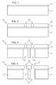
Figures 1-4 show a cross-sectional view of a membrane of nozzles according to one embodiment of the present invention; -
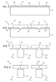
Figures 5-8 show a cross-sectional view of a membrane of nozzles according to another embodiment of the present invention; -
Figures 9-12 show a cross-sectional view of a membrane of nozzles according to a further embodiment of the present invention; -
Figures 13-16 show a cross-sectional view of a membrane of nozzles according to another embodiment of the present invention; -
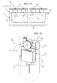
Figure 17 shows a spray device that incorporates a membrane of nozzles according to any of the embodiments of the present invention; and -
Figure 18 shows an inhaler that incorporates the spray device ofFigure 17 . - As is shown in
Figure 1 , according to one embodiment of the present invention, awafer 10 is provided, comprising asubstrate 11 made, for example, of silicon of an N type having a thickness of between 400 µm and 725 µm, preferably 400 µm. Asacrificial layer 12 is then provided, made, for example, of silicon oxide, which has a thickness of between 0.6 µm and 1.5 µm, preferably 0.8 µm. - Next (
Figure 2 ), amembrane layer 13, preferably made of non-doped polysilicon, is epitaxially grown on thewafer 10. ,. Alternatively, themembrane layer 13 may be made of deposited material, compatible with silicon processing technology (e.g., deposited polysilicon). Providing amembrane layer 13 made of grown or deposited material (thus differing from the substrate in either the material or the crystalline structure) has the advantage that the choice of the material to be used may be tuned according to the particular application of themembrane layer 13. In fact, by varying the material of themembrane layer 13, the properties of themembrane layer 13 are varied (e.g., its elasticity, compatibility with biological materials, etc.). - The
membrane layer 13 is then planarized until a final thickness is reached of between 1.5 µm and 10 µm, preferably 5 µm, and defined, for example, by means of dry etching so as to form a plurality of nozzles 14 (just twonozzles 14 are shown in the figure). Eachnozzle 14 has preferably, in top plan view, a circular shape with a diameter of between 1 µm and 5 µm, according to the liquid that is to be used, and extends in depth throughout the thickness of themembrane layer 13. - Then (
Figure 3 ), a step of grinding of the back of thesubstrate 11 enables reduction of the thickness of the substrate down to approximately 400 µm. This step is not necessary in the case where thestarting substrate 11 already has a thickness of 400 µm or less. - Next, formed in the
substrate 11, preferably by means of a dry etch, aresupply channels 15, each in a position corresponding, and substantially aligned vertically, to arespective nozzle 14. Thesupply channels 15 preferably have, in top plan view, a circular shape with a diameter of between 10 µm and 100 µm, preferably 40 µm, and extend in depth throughout the thickness of thesubstrate 11. - Finally (
Figure 4 ), thesacrificial layer 12 is partially removed, for example, by means of a wet etching of the buffered-oxide-etching (BOE) type so as to set in direct communication eachnozzle 14 with the respectiveunderlying supply channel 15. - A membrane of
nozzles 16 is thus obtained, provided with a plurality of nozzles 14 (for example, 3200 nozzles uniformly distributed on a membrane having an area of approximately 25 mm2) that can be used in a spray device. - The process described with reference to
Figures 1-4 enables formation ofnozzles 14 andsupply channels 15 all having respective uniform dimensions, hence guaranteeing high reproducibility, ease of production process, and extremely contained production costs. - The step of removal of the
sacrificial layer 12, in particular if performed by means of wet etching, can, however, be considered critical on account of a possible lateral overetching of the portions ofsacrificial layer 12, which could cause an excessive weakening of portions of the membrane ofnozzles 16 comprised between contiguous nozzles and consequent yielding of the membrane ofnozzles 16 itself. - In order to overcome said drawback, according to a further embodiment of the present invention, the
sacrificial layer 12, after being deposited, is defined so as to form portions isolated from one another ofsacrificial layer 12 in positions corresponding to the areas in which it is envisaged to form thenozzles 14. In greater detail, as shown inFigure 5 , thesacrificial layer 12, after being deposited on thesubstrate 11, is defined so as to formsacrificial isles 20 separated from one another by means oftrenches 21. Then (Figure 6 ), in a way similar to what has been described with reference toFigure 2 , themembrane layer 13 is grown and is defined, thus providing anozzle 14 in an area corresponding to eachsacrificial isle 20. In particular, in this case, themembrane layer 13 is formed also inside thetrenches 21, thus providingmembrane anchorages 22 for anchoring themembrane layer 13 directly to thesubstrate 11. - After an optional step of grinding of the back of the
substrate 11 to reduce the thickness thereof down to approximately 400 µm, the back of thesubstrate 11 is etched to form thesupply channels 15. - Finally (
Figure 8 ), thesacrificial isles 20 are removed by means of a wet etch, for example, with BOE, thus setting in direct contact eachnozzle 14 with therespective supply channel 15 to form a membrane ofnozzles 25. - According to this embodiment, a possible overetching of the oxide that forms the
sacrificial isles 20 does not jeopardize the mechanical stability of themembrane 25 in so far as themembrane anchorages 22 are not damaged by the steps of the process described. - In order to reduce the overall dimensions of the spray device in which the membrane of nozzles is used, it may prove convenient to reduce the thickness of the
substrate 11 and the depth of thesupply channels 15 so that they can be coupled to other types of piezoelectrics.Figures 9-12 show the steps of the process of formation of a membrane of nozzles, according to a further embodiment. - In a way similar to what has been described previously, with reference to
Figures 1 and 2 , awafer 10 is provided having asubstrate 11 on which asacrificial layer 12 is deposited and amembrane layer 13 is grown, in whichnozzles 14 are obtained, for example, by means of dry etching. - After formation of the nozzles 14 (
Figure 9 ), thewafer 10 is protected by means of aprotective layer 30, of a thickness of between 0.5 µm and 2 µm, preferably 1 µm, for example, made of thermally grown silicon oxide. In particular, theprotective layer 30 also coats the internal walls and the bottom of thenozzles 14. - Then (
Figure 10 ), theprotective layer 30 is removed from the back of thesubstrate 11 so as to create a window of a quadrangular shape underneath the plurality ofnozzles 14. A subsequent etching step, for example, wet etching with the use of tetramethylammonium hydroxide (TMAH) enables selective removal of thesubstrate 11 where this is not protected by theprotection layer 30 so as to provide achamber 31, having a depth of between 100 µm and 400 µm. For example, in the case where thesubstrate 11 has a thickness of 400 µm, it is preferable to form achamber 31 with a depth of 300 µm. During this etching step, theprotective layer 30 performs the dual function of mask for definition of the shape of thechamber 31 and of protection for preventing an undesirable etching of themembrane layer 13. - Next (
Figure 11 ), asupply channel 15 is formed underneath eachnozzle 14, by digging thesubstrate 11, for example, by means of a dry etch, until portions of thesacrificial layer 12 are exposed. Eachsupply channel 15 has a depth of between 50 µm and 300 µm. For example, in the case where thesubstrate 11 has a thickness of 400 µm and the chamber 31 a depth of 300 µm, eachsupply channel 15 will have a depth of 100 µm. - Finally (
Figure 12 ), theprotective layer 30 and the portions ofsacrificial layer 12 exposed are removed, for example, by means of wet etching of a BOE type, simultaneously providing a membrane ofnozzles 35 comprising a portion of a reservoir (the chamber 31). - In some cases it may be preferable to envisage membranes of nozzles provided with elements for guiding jets that, in use, come out of each
nozzle 14 so as to increase the directionality of the jet itself eliminating portions thereof having an angle of exit from thenozzle 14 greater than a certain maximum exit angle (assuming that each jet has a substantially conical shape). Membranes of nozzles of this type also prove to be more rigid. - For the above purpose, there may be envisaged formation of a guide channel, provided in a form integrated with the membrane of nozzles, set on each
nozzle 14, according to a further embodiment. - Said further embodiment is described in what follows with reference to
Figures 13-16 . - In a way similar to what has been described with reference to the embodiment of
Figures 5 and 6 , awafer 10 is provided, comprising asubstrate 11, on which asacrificial layer 12 is deposited and defined and amembrane layer 13 is grown, anchored to thesubstrate 11 by means ofmembrane anchorages 22. Thenozzles 14 are then formed by selectively removing portions of themembrane layer 13. - Next (
Figure 13 ), ashaping layer 40 is deposited, having a sacrificial function, so as to fill thenozzles 14 and form a layer on themembrane layer 13. Theshaping layer 40 may be made, for example, of silicon oxide, having a thickness of between 0.2 µm and 1 µm, preferably 0.5 µm. The shapinglayer 40 is defined so as to remove portions of the shapinglayer 40 laterally staggered with respect to eachnozzle 14, and kept in portions substantially aligned vertically to eachnozzle 14. - Then (
Figure 14 ), a guide-channel layer 41 is formed on thewafer 10, for example, by epitaxial growth of silicon having a thickness of between 2 µm and 6 µm, preferably 5 µm. - Next (
Figure 15 ), the guide-channel layer 41 is defined so as to form aguide channel 42 on top of, and substantially aligned vertically to, eachnozzle 14, having a preferably circular shape, a diameter of 5 µm, and a depth equal to the thickness of the guide-channel layer 41. In particular, the guide-channel layer 41 is selectively removed, for example, by means of dry etching, until the portions of the secondsacrificial layer 40 arranged on thenozzles 14 are at least partially exposed. - Then (
Figure 16 ), thesubstrate 11 is dug from the back to form asupply channel 15 for eachnozzle 14, in a way similar to what has been described with reference to the other embodiments illustrated. - A step of wet etching, for example, of the BOE type, enables removal of the portions of
sacrificial layer 12 and of shapinglayer 40 exposed in order to set in direct communication eachsupply channel 15 with therespective nozzle 14 and eachguide channel 42 with therespective nozzle 14. In this way, thesupply channel 15 and theguide channel 42 are in communication via thenozzle 14. A membrane ofnozzles 45 is thus provided. - It is clear that, as the size and the depth of the
guide channel 42 vary, the solid angle of the jet coming out of theguide channel 42 will vary accordingly. It is thus possible to provide membranes of nozzles equipped withguide channels 42 having different dimensions according to the desired directionality and amplitude of the jet, depending upon the use to which they will be put. - Furthermore, for simplicity, said embodiment has been described with preferred reference to the embodiment of
Figures 5-8 , in which the membrane is anchored to the substrate by means of themembrane anchorages 22. However, the process described for formation of theguide channels 42 may be applied, with obvious modifications, also to the other embodiments. -
Figure 17 shows aspray device 50 comprising a membrane ofnozzles - The
spray device 50 further comprises areservoir 51, set underneath the membrane ofnozzles internal housing 52 of its own a liquid substance 55 (for example, a medicament), which, in use, comes out of thenozzles 14 through thesupply channels 15. Actuation of thespray device 50 can be obtained in various ways, for example, by means of anactuator 53 of a piezoelectric type, fixed with respect to a bottom face of thereservoir 51 opposite to the membrane ofnozzles actuator 53 induces a vibration that is transmitted through thereservoir 51 to the liquid contained in thehousing 52, causing exit thereof through thenozzles 14. - Advantageously, an
inlet mouth 54 can be provided for recharging thereservoir 51 with furtherliquid substance 55, when theliquid substance 55, following upon use of thespray device 50, runs out. - The
spray device 50 can be incorporated in aninhaler 100, for controlled release of medicaments or anaesthetics. - The
inhaler 100 can comprise acontrol electronics 110, in turn comprising a control board, for controlling release of a precise amount of liquid medicament to be emitted. Thecontrol electronics 110 may comprise a frequency oscillator (not shown), for controlling the frequency of oscillation of theactuator 53, in the case where the latter is of a piezoelectric type. - Advantageously, the
control electronics 110 is supplied by abattery 104, integrated in theinhaler 100. - The
inhaler 100 can be activated by pressing apushbutton 105, which activates thecontrol electronics 110 for generating emission of the liquid medicament. - The
inhaler 100 can moreover comprise afluidic module 107, constituted by a plurality of channels and/orcontainers 108, connected to theinlet mouth 54 of thespray device 50 and designed to contain a certain amount of medicament for enabling a recharging of thespray device 50 when, following upon use, the medicament runs out. In turn, the channels and/orcontainers 108 can be recharged with medicament by the user, when necessary. - Finally, the
inhaler 100 may optionally comprise a flowmeter (not shown), set inside or outside thespray device 50, for evaluating the amount of liquid released, and/or a pressure sensor (not shown), for evaluating the level of liquid remaining within thereservoir 51 of thespray device 50. - From an examination of the characteristics of the process of fabrication according to the present invention, the advantages that it enables are evident.
- In particular the process of fabrication described, according to any one of the embodiments, presents a reduced cost, in so far as a limited number of process masks is required, and the membrane of nozzles is produced monolithically starting from a wafer of a standard type, without any need to use processes of a silicon-on-insulator (SOI) type or wafer-to-wafer-bonding processes.
- Finally, it is clear that modifications and variations may be made to the process described and illustrated herein, without thereby departing from the sphere of protection of the present invention, as defined in the annexed claims.
- For example, the
nozzles 14 can be formed at a time different from the one described, for example, after formation of thesupply channels 15.
Claims (15)
- A process for manufacturing a membrane of nozzles of a spray device, comprising the steps of:providing a substrate (11) of a first material;forming a membrane layer (13) of a second material on the substrate (11);forming a plurality of nozzles (14) in the membrane layer (13); andforming a plurality of supply channels (15) in the substrate (10), each supply channel being substantially aligned in a vertical direction to a respective nozzle (14) of said plurality of nozzles and in direct communication with the respective nozzle.
- The process according to claim 1, wherein said step of forming a membrane layer (13) comprises forming a membrane layer distinct from said substrate (11).
- The process according to claim 1 or 2, wherein the step of forming a membrane layer (13) comprises the step of growing or depositing said second material.
- The process according to claim 3, wherein said second material is polysilicon.
- The process according to any one of the preceding claims, wherein said first material of the substrate (11) is different from said second material of the membrane layer (13) or the first and second material are a same material in different crystalline states.
- The process according to any one of the preceding claims, further comprising the steps of forming a first sacrificial layer (12) between the substrate (11) and the membrane layer (13), selectively removing said first sacrificial layer, and directly connecting each supply channel (15) with the respective nozzle (14).
- The process according to claim 6, wherein the step of forming a first sacrificial layer (12) is performed before forming a membrane layer (13), the process further comprising, before forming a membrane layer (13), the step of removing selective portions of said first sacrificial layer (12) and forming trenches (21), said step of forming the membrane layer (13) comprising the step of forming membrane anchorages (22) anchored to the substrate through said trenches (21).
- The process according to any of the preceding claims, further comprising, before forming the supply channels (15), digging a back of the substrate (11) and forming a reservoir (31) in said substrate (11) underneath said plurality of nozzles (14).
- The process according to any of the preceding claims, further comprising the step of forming a plurality of guide channels (42), each guide channel extending on a respective nozzle (14) of said plurality of nozzles.
- The process according to claim 9, wherein the step of forming a plurality of guide channels (42) comprises the steps of:after the step of forming a plurality of nozzles, depositing a second sacrificial layer (40) on the membrane layer (13);selectively removing the second sacrificial layer in areas laterally offset with respect to the nozzles;growing a guide-channel layer (41) on the second sacrificial layer (40);removing selective portions of the guide-channel layer (41); andremoving the second sacrificial layer (40) and directly connecting each guide channel (42) with the respective nozzle (14).
- A spray device (50) comprising:a reservoir (51) having an inner chamber (52) configured so as to contain a liquid substance;an inlet mouth (54);an emission structure (16; 25; 35; 45) for emission of the liquid substance; andan actuator (53) connected to the reservoir (51) and configured so as to cause ejection of the liquid substance from the reservoir,characterized in that
said emission structure includes a membrane of nozzles (16; 25; 35; 45) made according to the manufacturing process of any of claims 1-10. - The spray device according to claim 11, wherein said membrane includes:a substrate (11) of a first material;a membrane layer (13) of a second material formed on the substrate; anda plurality of nozzles (14) formed through the membrane layer (13), said membrane layer being distinct from said substrate.
- The spray device according to claim 11 or 12, wherein said first material of the substrate (11) is different from the second material of the membrane layer (13) or the first and second material are a same material in different crystalline states.
- The spray device according to claim 13, wherein said second material is polysilicon.
- An inhaler (100) comprising the spray device (50) according to any one of claims 11-14.
Applications Claiming Priority (1)
| Application Number | Priority Date | Filing Date | Title |
|---|---|---|---|
| IT000980A ITTO20080980A1 (en) | 2008-12-23 | 2008-12-23 | PROCESS OF MANUFACTURING OF AN MEMBRANE OF NOZZLES INTEGRATED IN MEMS TECHNOLOGY FOR A NEBULIZATION DEVICE AND A NEBULIZATION DEVICE THAT USES THIS MEMBRANE |
Publications (2)
| Publication Number | Publication Date |
|---|---|
| EP2204238A1 true EP2204238A1 (en) | 2010-07-07 |
| EP2204238B1 EP2204238B1 (en) | 2014-10-29 |
Family
ID=41338484
Family Applications (1)
| Application Number | Title | Priority Date | Filing Date |
|---|---|---|---|
| EP09180395.7A Active EP2204238B1 (en) | 2008-12-23 | 2009-12-22 | Process for manufacturing an integrated membrane of nozzles in MEMS technology for a spray device |
Country Status (4)
| Country | Link |
|---|---|
| US (3) | US20100154790A1 (en) |
| EP (1) | EP2204238B1 (en) |
| JP (1) | JP2010167272A (en) |
| IT (1) | ITTO20080980A1 (en) |
Cited By (3)
| Publication number | Priority date | Publication date | Assignee | Title |
|---|---|---|---|---|
| CN104350182A (en) * | 2012-06-11 | 2015-02-11 | 斯坦福设备有限公司 | Method of manufacturing an orifice plate for a nebulizer |
| US10279357B2 (en) | 2014-05-23 | 2019-05-07 | Stamford Devices Limited | Method for producing an aperture plate |
| US10508353B2 (en) | 2010-12-28 | 2019-12-17 | Stamford Devices Limited | Photodefined aperture plate and method for producing the same |
Families Citing this family (29)
| Publication number | Priority date | Publication date | Assignee | Title |
|---|---|---|---|---|
| ITTO20080980A1 (en) * | 2008-12-23 | 2010-06-24 | St Microelectronics Srl | PROCESS OF MANUFACTURING OF AN MEMBRANE OF NOZZLES INTEGRATED IN MEMS TECHNOLOGY FOR A NEBULIZATION DEVICE AND A NEBULIZATION DEVICE THAT USES THIS MEMBRANE |
| US10066114B2 (en) | 2012-09-14 | 2018-09-04 | The Procter & Gamble Company | Ink jet delivery system comprising an improved perfume mixture |
| US11357931B2 (en) | 2013-07-22 | 2022-06-14 | Koninklijke Philips N.V. | Mesh for use in a nebuliser, and a method of manufacturing the same |
| US9211356B2 (en) | 2014-03-18 | 2015-12-15 | The Procter & Gamble Company | Ink jet delivery system comprising an improved fluid mixture |
| WO2015180079A1 (en) * | 2014-05-28 | 2015-12-03 | 王长津 | Micropore atomization sheet and micropore atomization apparatus |
| US9808812B2 (en) * | 2014-06-20 | 2017-11-07 | The Procter & Gamble Company | Microfluidic delivery system |
| US9278150B2 (en) | 2014-06-20 | 2016-03-08 | The Procter & Gamble Company | Method of delivering a dose of a fluid composition from a microfluidic delivery cartridge |
| US10076585B2 (en) | 2014-06-20 | 2018-09-18 | The Procter & Gamble Company | Method of delivering a dose of a fluid composition from a microfluidic delivery cartridge |
| US9433696B2 (en) | 2014-06-20 | 2016-09-06 | The Procter & Gamble Company | Microfluidic delivery system for releasing fluid compositions |
| US9211980B1 (en) | 2014-06-20 | 2015-12-15 | The Procter & Gamble Company | Microfluidic delivery system for releasing fluid compositions |
| CN107743421B (en) | 2015-06-11 | 2021-02-09 | 宝洁公司 | Apparatus and method for applying a composition to a surface |
| US20170072085A1 (en) | 2015-09-16 | 2017-03-16 | The Procter & Gamble Company | Microfluidic delivery system and cartridge |
| US9636430B2 (en) | 2015-09-16 | 2017-05-02 | The Procter & Gamble Company | Microfluidic delivery system and cartridge having an outer cover |
| US20170072086A1 (en) | 2015-09-16 | 2017-03-16 | The Procter & Gamble Company | Microfluidic delivery system and cartridge having an outer cover |
| BR112018011188B1 (en) | 2015-12-04 | 2021-02-02 | Medspray Bv | spray device for spraying a fluidic micro-jet spray and spray nozzle body |
| US20170333589A1 (en) | 2016-05-19 | 2017-11-23 | The Procter & Gamble Company | Methods for Dispensing Fluid Materials |
| US11090404B2 (en) | 2016-05-19 | 2021-08-17 | The Procter & Gamble Company | Systems for dispensing fluid materials |
| AU2017301690B2 (en) * | 2016-07-26 | 2022-03-10 | Prolitec Inc. | Air treatment appliance |
| US10675373B2 (en) * | 2016-07-27 | 2020-06-09 | Newmarket Concepts, Llc | Fragrance dispenser having a disposable piezoelectric cartridge with a snap-in bottle containing aromatic liquid |
| US10149917B2 (en) | 2016-11-22 | 2018-12-11 | The Procter & Gamble Company | Fluid composition and a microfluidic delivery cartridge comprising the same |
| US11305301B2 (en) | 2017-04-10 | 2022-04-19 | The Procter & Gamble Company | Microfluidic delivery device for dispensing and redirecting a fluid composition in the air |
| US11691162B2 (en) | 2017-04-10 | 2023-07-04 | The Procter & Gamble Company | Microfluidic delivery cartridge for use with a microfluidic delivery device |
| US20180290158A1 (en) | 2017-04-10 | 2018-10-11 | The Procter & Gamble Company | Microfluidic delivery device and method of jetting a fluid composition with the same |
| US12103020B2 (en) | 2017-04-10 | 2024-10-01 | The Procter & Gamble Company | Microfluidic delivery device and method for dispensing a fluid composition upward into the air |
| CN110621411B (en) * | 2017-05-31 | 2021-08-10 | 艾斯曲尔医疗公司 | Nozzle device and method for manufacturing the same |
| IT201800005372A1 (en) * | 2018-05-15 | 2019-11-15 | MICROFLUIDIC DEVICE FOR INHALABLE SUBSTANCES | |
| US10806816B2 (en) | 2018-05-15 | 2020-10-20 | The Procter & Gamble Company | Microfluidic cartridge and microfluidic delivery device comprising the same |
| CN116140123B (en) * | 2022-11-22 | 2026-02-17 | 上海声动微科技有限公司 | Atomizing chip and preparation method thereof |
| CN120359090A (en) * | 2022-12-14 | 2025-07-22 | 菲利普莫里斯生产公司 | Vibrating mesh module with integrated flow chamber |
Citations (5)
| Publication number | Priority date | Publication date | Assignee | Title |
|---|---|---|---|---|
| US6196219B1 (en) | 1997-11-19 | 2001-03-06 | Microflow Engineering Sa | Liquid droplet spray device for an inhaler suitable for respiratory therapies |
| EP1287905A1 (en) * | 2001-09-03 | 2003-03-05 | Microflow Engineering SA | Liquid droplet spray device |
| US20040155943A1 (en) * | 2003-02-07 | 2004-08-12 | Samsung Electronics Co., Ltd. | Bubble-ink jet print head and fabrication method thereof |
| US20050270334A1 (en) * | 1997-07-15 | 2005-12-08 | Silverbrook Research Pty Ltd | Ink jet nozzle arrangement having paddle forming a portion of a wall |
| US20060176338A1 (en) * | 2003-06-27 | 2006-08-10 | Sharp Kabushiki Kaisha | Nozzle plate and method of manufacturing the same |
Family Cites Families (10)
| Publication number | Priority date | Publication date | Assignee | Title |
|---|---|---|---|---|
| US7393083B2 (en) * | 1997-07-15 | 2008-07-01 | Silverbrook Research Pty Ltd | Inkjet printer with low nozzle to chamber cross-section ratio |
| DE1005917T1 (en) * | 1998-12-01 | 2001-01-11 | Microflow Engineering S.A., Neuenburg/Neuchatel | Inhaler with ultrasonic atomizer, the spray openings of which are superimposed on the maximum amplitudes of a standing wave pattern |
| US20060169800A1 (en) * | 1999-06-11 | 2006-08-03 | Aradigm Corporation | Aerosol created by directed flow of fluids and devices and methods for producing same |
| EP1236517A1 (en) * | 2001-02-23 | 2002-09-04 | Microflow Engineering SA | Method of manufacturing a liquid droplet spray device and such spray device |
| US6723077B2 (en) * | 2001-09-28 | 2004-04-20 | Hewlett-Packard Development Company, L.P. | Cutaneous administration system |
| DE10306683A1 (en) | 2003-02-13 | 2004-09-09 | Ing. Erich Pfeiffer Gmbh | microdosing |
| US7726303B2 (en) * | 2003-02-25 | 2010-06-01 | Hewlett-Packard Development Company, L.P. | Controlled medicament ejection |
| US20050150489A1 (en) * | 2004-01-12 | 2005-07-14 | Steve Dunfield | Dispensing medicaments based on rates of medicament action |
| US8882221B2 (en) * | 2008-08-21 | 2014-11-11 | Funai Electric Co., Ltd. | Modular micro-fluid ejection head assembly |
| ITTO20080980A1 (en) * | 2008-12-23 | 2010-06-24 | St Microelectronics Srl | PROCESS OF MANUFACTURING OF AN MEMBRANE OF NOZZLES INTEGRATED IN MEMS TECHNOLOGY FOR A NEBULIZATION DEVICE AND A NEBULIZATION DEVICE THAT USES THIS MEMBRANE |
-
2008
- 2008-12-23 IT IT000980A patent/ITTO20080980A1/en unknown
-
2009
- 2009-12-22 US US12/645,380 patent/US20100154790A1/en not_active Abandoned
- 2009-12-22 JP JP2009290875A patent/JP2010167272A/en active Pending
- 2009-12-22 EP EP09180395.7A patent/EP2204238B1/en active Active
-
2013
- 2013-01-30 US US13/754,510 patent/US8721910B2/en active Active
-
2014
- 2014-03-25 US US14/225,285 patent/US9486593B2/en active Active
Patent Citations (5)
| Publication number | Priority date | Publication date | Assignee | Title |
|---|---|---|---|---|
| US20050270334A1 (en) * | 1997-07-15 | 2005-12-08 | Silverbrook Research Pty Ltd | Ink jet nozzle arrangement having paddle forming a portion of a wall |
| US6196219B1 (en) | 1997-11-19 | 2001-03-06 | Microflow Engineering Sa | Liquid droplet spray device for an inhaler suitable for respiratory therapies |
| EP1287905A1 (en) * | 2001-09-03 | 2003-03-05 | Microflow Engineering SA | Liquid droplet spray device |
| US20040155943A1 (en) * | 2003-02-07 | 2004-08-12 | Samsung Electronics Co., Ltd. | Bubble-ink jet print head and fabrication method thereof |
| US20060176338A1 (en) * | 2003-06-27 | 2006-08-10 | Sharp Kabushiki Kaisha | Nozzle plate and method of manufacturing the same |
Cited By (13)
| Publication number | Priority date | Publication date | Assignee | Title |
|---|---|---|---|---|
| US10662543B2 (en) | 2010-12-28 | 2020-05-26 | Stamford Devices Limited | Photodefined aperture plate and method for producing the same |
| US10508353B2 (en) | 2010-12-28 | 2019-12-17 | Stamford Devices Limited | Photodefined aperture plate and method for producing the same |
| US11389601B2 (en) | 2010-12-28 | 2022-07-19 | Stamford Devices Limited | Photodefined aperture plate and method for producing the same |
| US11905615B2 (en) | 2010-12-28 | 2024-02-20 | Stamford Devices Limited | Photodefined aperture plate and method for producing the same |
| US12565710B2 (en) | 2010-12-28 | 2026-03-03 | Stamford Devices Limited | Photodefined aperture plate and method for producing the same |
| US9981090B2 (en) | 2012-06-11 | 2018-05-29 | Stamford Devices Limited | Method for producing an aperture plate |
| US10512736B2 (en) | 2012-06-11 | 2019-12-24 | Stamford Devices Limited | Aperture plate for a nebulizer |
| CN104350182B (en) * | 2012-06-11 | 2020-04-21 | 斯坦福设备有限公司 | Method of making an orifice plate for a nebulizer |
| CN104350182A (en) * | 2012-06-11 | 2015-02-11 | 斯坦福设备有限公司 | Method of manufacturing an orifice plate for a nebulizer |
| US11679209B2 (en) | 2012-06-11 | 2023-06-20 | Stamford Devices Limited | Aperture plate for a nebulizer |
| US10279357B2 (en) | 2014-05-23 | 2019-05-07 | Stamford Devices Limited | Method for producing an aperture plate |
| US11440030B2 (en) | 2014-05-23 | 2022-09-13 | Stamford Devices Limited | Method for producing an aperture plate |
| US11872573B2 (en) | 2014-05-23 | 2024-01-16 | Stamford Devices Limited | Method for producing an aperture plate |
Also Published As
| Publication number | Publication date |
|---|---|
| US8721910B2 (en) | 2014-05-13 |
| US20140202453A1 (en) | 2014-07-24 |
| US9486593B2 (en) | 2016-11-08 |
| ITTO20080980A1 (en) | 2010-06-24 |
| US20130134131A1 (en) | 2013-05-30 |
| US20100154790A1 (en) | 2010-06-24 |
| EP2204238B1 (en) | 2014-10-29 |
| JP2010167272A (en) | 2010-08-05 |
Similar Documents
| Publication | Publication Date | Title |
|---|---|---|
| EP2204238B1 (en) | Process for manufacturing an integrated membrane of nozzles in MEMS technology for a spray device | |
| JP7723465B2 (en) | Method for ejecting liquid from a liquid ejection device and method for manufacturing a liquid ejection device | |
| US8020973B2 (en) | Method of manufacturing a liquid droplet spray device and such spray device | |
| EP3423194B1 (en) | A monolithic integrated mesh device for fluid dispensers and method of making same | |
| CA2450367C (en) | Microneedles for minimally invasive drug delivery | |
| JP5118227B2 (en) | Nozzle formation of print head | |
| US9159899B2 (en) | Forming a membrane having curved features | |
| EP1364396A2 (en) | Microprotrusion array and methods of making a microprotrusion | |
| US20080245764A1 (en) | Method for producing a device including an array of microneedles on a support, and device producible according to this method | |
| JP2008132495A (en) | Liquid droplet spray device | |
| EP2390010B1 (en) | Nozzle body for an ultrasonic liquid droplet spray device | |
| EP1273355B1 (en) | Method of manufacturing a liquid droplet spray device and such spray device | |
| WO2015059437A1 (en) | Manufacture of microneedles | |
| EP1287904B1 (en) | Liquid droplet spray device | |
| CN101448646B (en) | Electrostatic actuator for ink jet heads | |
| US20220104544A1 (en) | Monolithic microfabricated vibrating mesh atomizer | |
| JP2014172103A (en) | Method of manufacturing uneven structure | |
| JP3598095B2 (en) | Driving part of micro atomizer and method of manufacturing the atomizer | |
| US9526885B1 (en) | Microneedles with sharpened tips and corresponding method of fabrication | |
| EP2147791A1 (en) | Method of manufacturing a droplet jetting device and an ink jet device | |
| WO2020163680A1 (en) | Monolithic microfabricated vibrating mesh atomizer | |
| US6886916B1 (en) | Piston-driven fluid-ejection apparatus | |
| EP1510261A1 (en) | Liquid droplet spray device having a hydrodynamic valve | |
| JP2008110560A (en) | Nozzle plate for liquid delivery head, and method for manufacturing nozzle plate for liquid delivering head |
Legal Events
| Date | Code | Title | Description |
|---|---|---|---|
| PUAI | Public reference made under article 153(3) epc to a published international application that has entered the european phase |
Free format text: ORIGINAL CODE: 0009012 |
|
| AK | Designated contracting states |
Kind code of ref document: A1 Designated state(s): AT BE BG CH CY CZ DE DK EE ES FI FR GB GR HR HU IE IS IT LI LT LU LV MC MK MT NL NO PL PT RO SE SI SK SM TR |
|
| AX | Request for extension of the european patent |
Extension state: AL BA RS |
|
| 17P | Request for examination filed |
Effective date: 20110107 |
|
| 17Q | First examination report despatched |
Effective date: 20110224 |
|
| RAP1 | Party data changed (applicant data changed or rights of an application transferred) |
Owner name: STMICROELECTRONICS SRL |
|
| RIC1 | Information provided on ipc code assigned before grant |
Ipc: B05B 1/14 20060101ALI20140331BHEP Ipc: B81C 1/00 20060101ALI20140331BHEP Ipc: B05B 17/06 20060101AFI20140331BHEP Ipc: B05B 17/00 20060101ALI20140331BHEP Ipc: B05D 7/00 20060101ALI20140331BHEP |
|
| GRAP | Despatch of communication of intention to grant a patent |
Free format text: ORIGINAL CODE: EPIDOSNIGR1 |
|
| INTG | Intention to grant announced |
Effective date: 20140523 |
|
| GRAS | Grant fee paid |
Free format text: ORIGINAL CODE: EPIDOSNIGR3 |
|
| GRAA | (expected) grant |
Free format text: ORIGINAL CODE: 0009210 |
|
| AK | Designated contracting states |
Kind code of ref document: B1 Designated state(s): AT BE BG CH CY CZ DE DK EE ES FI FR GB GR HR HU IE IS IT LI LT LU LV MC MK MT NL NO PL PT RO SE SI SK SM TR |
|
| REG | Reference to a national code |
Ref country code: GB Ref legal event code: FG4D |
|
| REG | Reference to a national code |
Ref country code: CH Ref legal event code: EP |
|
| REG | Reference to a national code |
Ref country code: AT Ref legal event code: REF Ref document number: 693291 Country of ref document: AT Kind code of ref document: T Effective date: 20141115 |
|
| REG | Reference to a national code |
Ref country code: IE Ref legal event code: FG4D |
|
| REG | Reference to a national code |
Ref country code: DE Ref legal event code: R096 Ref document number: 602009027417 Country of ref document: DE Effective date: 20141211 |
|
| REG | Reference to a national code |
Ref country code: AT Ref legal event code: MK05 Ref document number: 693291 Country of ref document: AT Kind code of ref document: T Effective date: 20141029 |
|
| REG | Reference to a national code |
Ref country code: NL Ref legal event code: VDEP Effective date: 20141029 |
|
| REG | Reference to a national code |
Ref country code: LT Ref legal event code: MG4D |
|
| PG25 | Lapsed in a contracting state [announced via postgrant information from national office to epo] |
Ref country code: FI Free format text: LAPSE BECAUSE OF FAILURE TO SUBMIT A TRANSLATION OF THE DESCRIPTION OR TO PAY THE FEE WITHIN THE PRESCRIBED TIME-LIMIT Effective date: 20141029 Ref country code: ES Free format text: LAPSE BECAUSE OF FAILURE TO SUBMIT A TRANSLATION OF THE DESCRIPTION OR TO PAY THE FEE WITHIN THE PRESCRIBED TIME-LIMIT Effective date: 20141029 Ref country code: LT Free format text: LAPSE BECAUSE OF FAILURE TO SUBMIT A TRANSLATION OF THE DESCRIPTION OR TO PAY THE FEE WITHIN THE PRESCRIBED TIME-LIMIT Effective date: 20141029 Ref country code: NL Free format text: LAPSE BECAUSE OF FAILURE TO SUBMIT A TRANSLATION OF THE DESCRIPTION OR TO PAY THE FEE WITHIN THE PRESCRIBED TIME-LIMIT Effective date: 20141029 Ref country code: IS Free format text: LAPSE BECAUSE OF FAILURE TO SUBMIT A TRANSLATION OF THE DESCRIPTION OR TO PAY THE FEE WITHIN THE PRESCRIBED TIME-LIMIT Effective date: 20150228 Ref country code: PT Free format text: LAPSE BECAUSE OF FAILURE TO SUBMIT A TRANSLATION OF THE DESCRIPTION OR TO PAY THE FEE WITHIN THE PRESCRIBED TIME-LIMIT Effective date: 20150302 Ref country code: NO Free format text: LAPSE BECAUSE OF FAILURE TO SUBMIT A TRANSLATION OF THE DESCRIPTION OR TO PAY THE FEE WITHIN THE PRESCRIBED TIME-LIMIT Effective date: 20150129 |
|
| PG25 | Lapsed in a contracting state [announced via postgrant information from national office to epo] |
Ref country code: LV Free format text: LAPSE BECAUSE OF FAILURE TO SUBMIT A TRANSLATION OF THE DESCRIPTION OR TO PAY THE FEE WITHIN THE PRESCRIBED TIME-LIMIT Effective date: 20141029 Ref country code: HR Free format text: LAPSE BECAUSE OF FAILURE TO SUBMIT A TRANSLATION OF THE DESCRIPTION OR TO PAY THE FEE WITHIN THE PRESCRIBED TIME-LIMIT Effective date: 20141029 Ref country code: SE Free format text: LAPSE BECAUSE OF FAILURE TO SUBMIT A TRANSLATION OF THE DESCRIPTION OR TO PAY THE FEE WITHIN THE PRESCRIBED TIME-LIMIT Effective date: 20141029 Ref country code: AT Free format text: LAPSE BECAUSE OF FAILURE TO SUBMIT A TRANSLATION OF THE DESCRIPTION OR TO PAY THE FEE WITHIN THE PRESCRIBED TIME-LIMIT Effective date: 20141029 Ref country code: CY Free format text: LAPSE BECAUSE OF FAILURE TO SUBMIT A TRANSLATION OF THE DESCRIPTION OR TO PAY THE FEE WITHIN THE PRESCRIBED TIME-LIMIT Effective date: 20141029 Ref country code: PL Free format text: LAPSE BECAUSE OF FAILURE TO SUBMIT A TRANSLATION OF THE DESCRIPTION OR TO PAY THE FEE WITHIN THE PRESCRIBED TIME-LIMIT Effective date: 20141029 Ref country code: GR Free format text: LAPSE BECAUSE OF FAILURE TO SUBMIT A TRANSLATION OF THE DESCRIPTION OR TO PAY THE FEE WITHIN THE PRESCRIBED TIME-LIMIT Effective date: 20150130 |
|
| PG25 | Lapsed in a contracting state [announced via postgrant information from national office to epo] |
Ref country code: BE Free format text: LAPSE BECAUSE OF NON-PAYMENT OF DUE FEES Effective date: 20141231 |
|
| REG | Reference to a national code |
Ref country code: DE Ref legal event code: R097 Ref document number: 602009027417 Country of ref document: DE |
|
| PG25 | Lapsed in a contracting state [announced via postgrant information from national office to epo] |
Ref country code: LU Free format text: LAPSE BECAUSE OF FAILURE TO SUBMIT A TRANSLATION OF THE DESCRIPTION OR TO PAY THE FEE WITHIN THE PRESCRIBED TIME-LIMIT Effective date: 20141222 Ref country code: DK Free format text: LAPSE BECAUSE OF FAILURE TO SUBMIT A TRANSLATION OF THE DESCRIPTION OR TO PAY THE FEE WITHIN THE PRESCRIBED TIME-LIMIT Effective date: 20141029 Ref country code: SK Free format text: LAPSE BECAUSE OF FAILURE TO SUBMIT A TRANSLATION OF THE DESCRIPTION OR TO PAY THE FEE WITHIN THE PRESCRIBED TIME-LIMIT Effective date: 20141029 Ref country code: EE Free format text: LAPSE BECAUSE OF FAILURE TO SUBMIT A TRANSLATION OF THE DESCRIPTION OR TO PAY THE FEE WITHIN THE PRESCRIBED TIME-LIMIT Effective date: 20141029 Ref country code: RO Free format text: LAPSE BECAUSE OF FAILURE TO SUBMIT A TRANSLATION OF THE DESCRIPTION OR TO PAY THE FEE WITHIN THE PRESCRIBED TIME-LIMIT Effective date: 20141029 Ref country code: CZ Free format text: LAPSE BECAUSE OF FAILURE TO SUBMIT A TRANSLATION OF THE DESCRIPTION OR TO PAY THE FEE WITHIN THE PRESCRIBED TIME-LIMIT Effective date: 20141029 |
|
| REG | Reference to a national code |
Ref country code: CH Ref legal event code: PL |
|
| PG25 | Lapsed in a contracting state [announced via postgrant information from national office to epo] |
Ref country code: IT Free format text: LAPSE BECAUSE OF FAILURE TO SUBMIT A TRANSLATION OF THE DESCRIPTION OR TO PAY THE FEE WITHIN THE PRESCRIBED TIME-LIMIT Effective date: 20141029 |
|
| PLBE | No opposition filed within time limit |
Free format text: ORIGINAL CODE: 0009261 |
|
| STAA | Information on the status of an ep patent application or granted ep patent |
Free format text: STATUS: NO OPPOSITION FILED WITHIN TIME LIMIT |
|
| GBPC | Gb: european patent ceased through non-payment of renewal fee |
Effective date: 20150129 |
|
| REG | Reference to a national code |
Ref country code: IE Ref legal event code: MM4A |
|
| REG | Reference to a national code |
Ref country code: FR Ref legal event code: ST Effective date: 20150831 |
|
| 26N | No opposition filed |
Effective date: 20150730 |
|
| PG25 | Lapsed in a contracting state [announced via postgrant information from national office to epo] |
Ref country code: CH Free format text: LAPSE BECAUSE OF NON-PAYMENT OF DUE FEES Effective date: 20141231 Ref country code: LI Free format text: LAPSE BECAUSE OF NON-PAYMENT OF DUE FEES Effective date: 20141231 Ref country code: IE Free format text: LAPSE BECAUSE OF NON-PAYMENT OF DUE FEES Effective date: 20141222 Ref country code: GB Free format text: LAPSE BECAUSE OF NON-PAYMENT OF DUE FEES Effective date: 20150129 |
|
| PG25 | Lapsed in a contracting state [announced via postgrant information from national office to epo] |
Ref country code: FR Free format text: LAPSE BECAUSE OF NON-PAYMENT OF DUE FEES Effective date: 20141231 |
|
| PG25 | Lapsed in a contracting state [announced via postgrant information from national office to epo] |
Ref country code: SI Free format text: LAPSE BECAUSE OF FAILURE TO SUBMIT A TRANSLATION OF THE DESCRIPTION OR TO PAY THE FEE WITHIN THE PRESCRIBED TIME-LIMIT Effective date: 20141029 |
|
| PG25 | Lapsed in a contracting state [announced via postgrant information from national office to epo] |
Ref country code: SM Free format text: LAPSE BECAUSE OF FAILURE TO SUBMIT A TRANSLATION OF THE DESCRIPTION OR TO PAY THE FEE WITHIN THE PRESCRIBED TIME-LIMIT Effective date: 20141029 |
|
| PG25 | Lapsed in a contracting state [announced via postgrant information from national office to epo] |
Ref country code: MC Free format text: LAPSE BECAUSE OF FAILURE TO SUBMIT A TRANSLATION OF THE DESCRIPTION OR TO PAY THE FEE WITHIN THE PRESCRIBED TIME-LIMIT Effective date: 20141029 |
|
| PG25 | Lapsed in a contracting state [announced via postgrant information from national office to epo] |
Ref country code: BG Free format text: LAPSE BECAUSE OF FAILURE TO SUBMIT A TRANSLATION OF THE DESCRIPTION OR TO PAY THE FEE WITHIN THE PRESCRIBED TIME-LIMIT Effective date: 20141029 |
|
| PG25 | Lapsed in a contracting state [announced via postgrant information from national office to epo] |
Ref country code: MT Free format text: LAPSE BECAUSE OF FAILURE TO SUBMIT A TRANSLATION OF THE DESCRIPTION OR TO PAY THE FEE WITHIN THE PRESCRIBED TIME-LIMIT Effective date: 20141029 Ref country code: HU Free format text: LAPSE BECAUSE OF FAILURE TO SUBMIT A TRANSLATION OF THE DESCRIPTION OR TO PAY THE FEE WITHIN THE PRESCRIBED TIME-LIMIT; INVALID AB INITIO Effective date: 20091222 Ref country code: TR Free format text: LAPSE BECAUSE OF FAILURE TO SUBMIT A TRANSLATION OF THE DESCRIPTION OR TO PAY THE FEE WITHIN THE PRESCRIBED TIME-LIMIT Effective date: 20141029 |
|
| REG | Reference to a national code |
Ref country code: DE Ref legal event code: R082 Ref document number: 602009027417 Country of ref document: DE Representative=s name: SCHMITT-NILSON SCHRAUD WAIBEL WOHLFROM PATENTA, DE |
|
| PG25 | Lapsed in a contracting state [announced via postgrant information from national office to epo] |
Ref country code: MK Free format text: LAPSE BECAUSE OF FAILURE TO SUBMIT A TRANSLATION OF THE DESCRIPTION OR TO PAY THE FEE WITHIN THE PRESCRIBED TIME-LIMIT Effective date: 20141029 |
|
| PGFP | Annual fee paid to national office [announced via postgrant information from national office to epo] |
Ref country code: DE Payment date: 20251126 Year of fee payment: 17 |