EP2204214A1 - Clamping assembly for use with a catheter - Google Patents
Clamping assembly for use with a catheter Download PDFInfo
- Publication number
- EP2204214A1 EP2204214A1 EP09180737A EP09180737A EP2204214A1 EP 2204214 A1 EP2204214 A1 EP 2204214A1 EP 09180737 A EP09180737 A EP 09180737A EP 09180737 A EP09180737 A EP 09180737A EP 2204214 A1 EP2204214 A1 EP 2204214A1
- Authority
- EP
- European Patent Office
- Prior art keywords
- slide member
- clamping assembly
- body portion
- arcuate body
- base
- Prior art date
- Legal status (The legal status is an assumption and is not a legal conclusion. Google has not performed a legal analysis and makes no representation as to the accuracy of the status listed.)
- Granted
Links
- 239000012858 resilient material Substances 0.000 claims description 3
- 239000008280 blood Substances 0.000 description 8
- 210000004369 blood Anatomy 0.000 description 8
- 239000012530 fluid Substances 0.000 description 6
- 238000000034 method Methods 0.000 description 6
- 238000001631 haemodialysis Methods 0.000 description 5
- 230000000322 hemodialysis Effects 0.000 description 5
- 230000000712 assembly Effects 0.000 description 4
- 238000000429 assembly Methods 0.000 description 4
- 210000004204 blood vessel Anatomy 0.000 description 2
- 238000012986 modification Methods 0.000 description 2
- 230000004048 modification Effects 0.000 description 2
- 230000009977 dual effect Effects 0.000 description 1
- 239000003053 toxin Substances 0.000 description 1
- 231100000765 toxin Toxicity 0.000 description 1
- 108700012359 toxins Proteins 0.000 description 1
- 238000012800 visualization Methods 0.000 description 1
- 239000002699 waste material Substances 0.000 description 1
Images




Classifications
-
- A—HUMAN NECESSITIES
- A61—MEDICAL OR VETERINARY SCIENCE; HYGIENE
- A61M—DEVICES FOR INTRODUCING MEDIA INTO, OR ONTO, THE BODY; DEVICES FOR TRANSDUCING BODY MEDIA OR FOR TAKING MEDIA FROM THE BODY; DEVICES FOR PRODUCING OR ENDING SLEEP OR STUPOR
- A61M39/00—Tubes, tube connectors, tube couplings, valves, access sites or the like, specially adapted for medical use
- A61M39/22—Valves or arrangement of valves
- A61M39/28—Clamping means for squeezing flexible tubes, e.g. roller clamps
- A61M39/285—Cam clamps, e.g. roller clamps with eccentric axis
-
- A—HUMAN NECESSITIES
- A61—MEDICAL OR VETERINARY SCIENCE; HYGIENE
- A61M—DEVICES FOR INTRODUCING MEDIA INTO, OR ONTO, THE BODY; DEVICES FOR TRANSDUCING BODY MEDIA OR FOR TAKING MEDIA FROM THE BODY; DEVICES FOR PRODUCING OR ENDING SLEEP OR STUPOR
- A61M39/00—Tubes, tube connectors, tube couplings, valves, access sites or the like, specially adapted for medical use
- A61M39/22—Valves or arrangement of valves
- A61M39/28—Clamping means for squeezing flexible tubes, e.g. roller clamps
- A61M39/286—Wedge clamps, e.g. roller clamps with inclined guides
-
- Y—GENERAL TAGGING OF NEW TECHNOLOGICAL DEVELOPMENTS; GENERAL TAGGING OF CROSS-SECTIONAL TECHNOLOGIES SPANNING OVER SEVERAL SECTIONS OF THE IPC; TECHNICAL SUBJECTS COVERED BY FORMER USPC CROSS-REFERENCE ART COLLECTIONS [XRACs] AND DIGESTS
- Y10—TECHNICAL SUBJECTS COVERED BY FORMER USPC
- Y10T—TECHNICAL SUBJECTS COVERED BY FORMER US CLASSIFICATION
- Y10T24/00—Buckles, buttons, clasps, etc.
- Y10T24/44—Clasp, clip, support-clamp, or required component thereof
- Y10T24/44573—Clasp, clip, support-clamp, or required component thereof including track or way guided and retained gripping member
Definitions
- the present disclosure generally relates to a clamp for obstructing flow through a fluid conduit, and, in particular, relates to clamping assemblies for obstructing fluid flow through extension tubes of a catheter assembly.
- Catheters are flexible medical devices that facilitate the withdrawal and introduction of fluids from and to body cavities, ducts, and vessels. Catheters may have particular application in a hemodialysis procedure where blood is withdrawn from a blood vessel for treatment, and subsequently returned to the blood vessel for circulation.
- Known hemodialysis catheters include multiple lumens, such as dual lumen or triple-lumen catheters, which permit bi-directional fluid flow within the catheter whereby one lumen is dedicated for withdrawal of blood from a vessel and the other lumen is dedicated for returning treated blood to the vessel.
- a multiple lumen catheter is inserted into a body vessel and blood is withdrawn through an arterial lumen of the catheter.
- the removed blood is directed to a hemodialysis unit which dialyzes, or purifies, the blood to remove waste and toxins from the blood.
- the dialyzed blood is returned to the patient through a venous lumen of the catheter.
- Catheter assemblies often have one or more extension tubes.
- clinicians clamp the extension tubes to occlude flow at certain stages of a medical procedure.
- clamping of the extension tubes is usually required in between medical procedures.
- a low-profile clamp that rests comfortably against the patient's skin would provide an improved quality of life.
- a number of clamps have been developed over the years. Improvements to known clamps that can provide a more comfortable patient experience are desirable.
- the present disclosure relates to a clamping assembly.
- This clamping assembly includes a body having a base and an arcuate body portion secured to the base.
- the arcuate body portion defining at least one opening dimensioned to receive a tubular member having a lumen.
- the clamping assembly further includes a slide member adapted to slide along the arcuate portion between an open position and a closed position. The slide member is movable along the arcuate body portion to compress the tubular member received within the body against the base to obstruct the lumen of the tubular member when the slide member is in the closed position.
- the base is flat and adapted to support the tubular member.
- the arcuate body portion is secured to the ends of the base.
- a lateral open space is defined between the flat base and the arcuate body portion.
- At least one opening includes a first opening and an aperture dimensioned to receive the tubular member, the aperture being located in a first section of the arcuate body portion.
- the clamping assembly further includes a second opening located in a proximal section of the arcuate body portion.
- the arcuate body portion includes at least one feature which is releasably engagable with a corresponding feature on the slide member to releseably secure the slide member in the closed position.
- the arcuate body portion includes a plurality of detents, each detent being adapted to secure the slide member at a predetermined secured position along the arcuate body portion.
- the slide member includes an engagement member configured to releasably engage a detent of the plurality of detents to retain the slide member in relation to the arcuate body portion.
- the slide member includes a first portion facing away from the base and a second portion facing toward the base, the first portion including the engagement member.
- the second portion of the slide member includes a blunt protuberance configured to compress the tubular member.
- the first and second portions of the slide member are configured to spread apart when the slide member moves between the predetermined secured positions.
- the clamping assembly further includes a track positioned along the arcuate body portion, wherein the track is configured to slidably receive the second portion of the slide member to facilitate movement of the slide member along the arcuate body portion.
- the slide member is made of a resilient material.
- the slide member has a substantially C-shape.
- the plurality of detents includes a detent positioned to retain the slide member at an intermediate position between the open and closed positions.
- the present disclosure further relates to a catheter assembly including a catheter defining a bore, a body, and a slide member.
- the body has a base and an arcuate body portion secured to the base.
- the base is configured to support the catheter.
- the slide member is slidably positioned on the arcuate body portion.
- the slide member is adapted to slide along the arcuate body portion between an open position and a closed position.
- the slide member is movable along the arcuate body portion to compress the catheter to occlude the bore when the slide member is in the closed position.
- the body defines at least one opening dimensioned to receive the catheter.
- the arcuate body portion includes a plurality of detents, each detent being adapted to secure the slide member at a predetermined secured position.
- the slide member includes an engagement protrusion configured to securely engage a detent of the plurality of detents to fix the position of the slide member along the arcuate portion at the predetermined secured positions.
- the slide member has a substantially C-shape.
- the present disclosure further relates to a clamping assembly including a body and a slide member.
- the body has a base and an arcuate body portion secured to the base.
- the arcuate body portion defines a first opening, a second opening located in a proximal section of the arcuate body portion, and an aperture dimensioned to receive a tubular member having a lumen.
- the aperture is located in a first section of the arcuate body portion.
- the arcuate body portion includes at least one feature which is releasably engagable with a corresponding feature on the slide member to releasably secure the slide member in the closed position.
- the slide member is adapted to slide along the arcuate portion between an open position and a closed position. The slide member is movable along the arcuate body portion to compress the tubular member received within the body against the base to obstruct the lumen of the tubular member when the slide member is in the closed position.
- Fig. 1 is a perspective view of a clamping assembly for a catheter in accordance with an embodiment of the present disclosure
- Fig. 2 is a side cross-sectional view of the clamping assembly shown in Fig. 1 with a slide member in an open position;
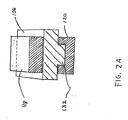
- Fig. 2A is a front cross-sectional view of the clamping assembly shown in Fig. 1 ;
- Fig. 3 is an enlarged side cross-sectional view showing the indicated area of detail shown in Fig. 2 ;
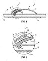
- Fig. 4 is a side cross-sectional view of the clamping assembly shown in Fig. 1 with the slide member in an intermediate position;
- Fig. 5 is an enlarged side cross-sectional view showing the indicated area of detail shown in Fig. 4 ;
- Fig. 6 is a side cross-sectional view of the clamping assembly shown in Fig. 1 with the slide member moving towards the closed position;
- Fig. 7 is an enlarged side cross-sectional view showing the indicated area of detail shown in Fig. 6 ;
- Fig. 8 is a side cross-sectional view of the clamping assembly shown in Fig. 1 with the slide member in the closed position;
- Fig. 9 is an enlarged side cross-sectional view showing the indicated area of detail shown in Fig. 8 .
- proximal or distal will refer to the portion of a structure that is closer to a clinician, while the term “distal” or “leading” will refer to the portion that is farther from the clinician.
- subject refers to a human patient or other animal.
- patient refers to a human patient or other animal.
- patient refers to a physician, nurse or other care provider and may include support personnel.
- Fig. 1 shows an embodiment of a clamping assembly 100 for clamping a tubular member 200 defining a bore 202, e.g., a catheter, an extension tube, or any other suitable fluid conduit.
- Clamping assembly 100 includes a body 102 having a flat base 104 and an arcuate body portion 106 secured to flat base 104.
- Body 102 defines lateral open spaces 130 on each side of body 102 to facilitate visualization of tubular member 200 during operation of clamping assembly 100. Lateral open spaces 130 are defined between arcuate body portion 106 and flat base 104.
- Flat base 104 is adapted to support at least a portion of tubular member 200 along its inner surface. In use, flat base 104 may rest on a subject's skin while the clinician performs the appropriate medical procedure.
- Arcuate body portion 106 has a proximal section 112 and a distal section 114. Only proximal and distal sections 112, 114 of arcuate body portion 106 directly contact flat base 104. Arcuate portion 106 further includes an opening 108 located in proximal section 112 and an aperture 110 located in distal section 114. Opening 108 and aperture 110 are both dimensioned to receive tubular member 200. As seen in Fig. 1 , opening 108 and aperture 110 together allow passage of catheter 200 through body 102 of clamping assembly 100. Openings 108, 110 can be defined by non-parallel walls as shown in Fig. 1 or alternatively by parallel walls.
- Clamping assembly 100 further includes a slide member 116 adapted slide along arcuate portion 106 between an open position (see Fig. 2 ) and a closed position (see Fig. 8 ).
- the slide member 116 In the open position, the slide member 116 is spaced above flat base 104 such that slide member 116 does not compress tubular member 200 positioned within body 102 to permit flow through bore 202 of tubular member 200.
- slide member 116 In the closed position, slide member 116 compresses tubular member 200 and prevents flow through bore 202 of tubular member 200.
- Slide member 116 features a substantially C-shape and includes a first or upper portion 118 facing away from flat base 104 and a second or lower portion 120 facing flat base 104. In one embodiment, at least a section of lower portion 120 may ride along a track 132 (see Fig. 2A ) defined on arcuate body portion 106 to facilitate movement of slide member 116 along arcuate body portion 106.
- Slide member 116 and arcuate body portion 106 include corresponding features for frictional or other mechanical engagement to releasably secure slide member 116 in at least a closed position.
- engagement features include detents, textured surfaces, and biased locking members.
- first portion 118 of slide member 116 includes downwardly extending engagement protrusion 122 configured to securely engage a stop member or detent 124a or 124b formed on arcuate body portion 106.
- First portion 118 of slide member 116 includes an engagement member 128 disposed proximal to engagement protrusion 122.
- Second portion 120 of slide member 116 has a blunt protuberance 126 adapted to compress tubular member 200.
- slide member 116 is made of a resilient material and first and second portions 118, 120 are configured to spread apart or expand outwardly when slide member 116 moves between detents 124a, 124b of arcuate body portion 106.
- Arcuate body portion 106 includes one or more stop members or detents 124a, 124b disposed at predetermined secured positions. Each detent 124a, 124b is adapted to securely engage engagement protrusion 122 of slide member 116 to fix the position of slide member 116 relative to arcuate portion 106. Detents 124a, 124b allow the clinician to lock slide member 116 at multiple predetermined secured positions along arcuate portion 106. In one embodiment, in the open position, slide member 116 does not engage detents 124a, 124b and therefore is not secured relative to the arcuate portion 106. Alternatively, slide member 116 can engage a detent (not shown) while located in the open position.
- Figs. 2 and 3 illustrate clamping assembly 100 with slide member 116 located in the open position and tubular member 200 supported by flat base 104.
- engagement protrusion 122 does not engage detents 124a, 124b and thus slide member 116 is free to slide along arcuate portion 106.
- blunt protuberance 126 may contact tubular member 200 while slide member is in the open position, blunt protuberance 126 does not press tubular member 200 against flat base 104.
- slide member 116 does not obstruct flow through bore 202 of tubular member 200.
- a clinician can move slide member 116 distally along arcuate body portion 106 from the open position to an intermediate position to progressively close bore 202 of tubular member 200.
- first and second portions 118, 120 briefly separate from each other while engagement protrusion 122 passes over detent 124a to a position between detents 124a and 124b, i.e, the intermediate position.
- first and second portions 118, 120 of slide member 116 return to their original position and engagement protrusion 122 securely engages detent 124a to lock slide member 116 in the intermediate position.
- blunt protuberance 126 presses tubular member 200 against flat base 104, partially compressing tubular member 200.
- slide member 116 partially occludes flow through bore 202 of tubular member 200.
- a clinician can move slide member 116 distally along arcuate portion 106 from the intermediate position to the closed position.
- engagement protrusion 122 slides over detent 124b.
- first portion 118 deflects outwardly from second portion 120 of slide member 116 as shown in Fig. 7 .
- the resilience of slide member 116 allows first and second portions 118, 120 to deflect outwardly from each other and return to their original position after slide member 116 has passed over detent 124b.
- engagement protrusion 122 securely engages detent 124b to lock slide member 116 in the closed position.
- blunt protuberance 126 presses tubular member 200 against flat base 104 to prevent flow through bore 202 of tubular member 200.
- the pressure exerted by slide member 116 on tubular member 200 collapses a portion of tubular member 200 and completely obstructs flow through bore 202.
- the clinician can deflect engagement member 128 upwardly to separate the first portion 118 of slide member 116 from the second portion 120. Once the first and second portions 118, 120 of slide member 116 have been separated from each other, the clinician can displace slide member 116 along arcuate body portion 106 to the open position or any other desired position.
- the presently disclosed clamping assemblies may clamp any conduit capable of transferring fluid from one point to another. Therefore, the above description should not be construed as limiting, but merely as exemplifications of embodiments. Those skilled in the art will envision other modifications within the scope and spirit of the present disclosure.
Landscapes
- Health & Medical Sciences (AREA)
- Heart & Thoracic Surgery (AREA)
- Hematology (AREA)
- Engineering & Computer Science (AREA)
- Anesthesiology (AREA)
- Biomedical Technology (AREA)
- Pulmonology (AREA)
- Life Sciences & Earth Sciences (AREA)
- Animal Behavior & Ethology (AREA)
- General Health & Medical Sciences (AREA)
- Public Health (AREA)
- Veterinary Medicine (AREA)
- Infusion, Injection, And Reservoir Apparatuses (AREA)
- Media Introduction/Drainage Providing Device (AREA)
Abstract
Description
- The present disclosure generally relates to a clamp for obstructing flow through a fluid conduit, and, in particular, relates to clamping assemblies for obstructing fluid flow through extension tubes of a catheter assembly.
- Catheters are flexible medical devices that facilitate the withdrawal and introduction of fluids from and to body cavities, ducts, and vessels. Catheters may have particular application in a hemodialysis procedure where blood is withdrawn from a blood vessel for treatment, and subsequently returned to the blood vessel for circulation. Known hemodialysis catheters include multiple lumens, such as dual lumen or triple-lumen catheters, which permit bi-directional fluid flow within the catheter whereby one lumen is dedicated for withdrawal of blood from a vessel and the other lumen is dedicated for returning treated blood to the vessel. During an exemplary hemodialysis procedure, a multiple lumen catheter is inserted into a body vessel and blood is withdrawn through an arterial lumen of the catheter. The removed blood is directed to a hemodialysis unit which dialyzes, or purifies, the blood to remove waste and toxins from the blood. The dialyzed blood is returned to the patient through a venous lumen of the catheter.
- Catheter assemblies often have one or more extension tubes. In hemodialysis and other medical procedures, clinicians clamp the extension tubes to occlude flow at certain stages of a medical procedure. In addition, clamping of the extension tubes is usually required in between medical procedures. A low-profile clamp that rests comfortably against the patient's skin would provide an improved quality of life. A number of clamps have been developed over the years. Improvements to known clamps that can provide a more comfortable patient experience are desirable.
- The present disclosure relates to a clamping assembly. This clamping assembly includes a body having a base and an arcuate body portion secured to the base. The arcuate body portion defining at least one opening dimensioned to receive a tubular member having a lumen. The clamping assembly further includes a slide member adapted to slide along the arcuate portion between an open position and a closed position. The slide member is movable along the arcuate body portion to compress the tubular member received within the body against the base to obstruct the lumen of the tubular member when the slide member is in the closed position.
- In one embodiment, the base is flat and adapted to support the tubular member.
- In one embodiment, the arcuate body portion is secured to the ends of the base.
- In one embodiment, a lateral open space is defined between the flat base and the arcuate body portion.
- In one embodiment, at least one opening includes a first opening and an aperture dimensioned to receive the tubular member, the aperture being located in a first section of the arcuate body portion.
- In one embodiment, the clamping assembly further includes a second opening located in a proximal section of the arcuate body portion.
- In one embodiment, the arcuate body portion includes at least one feature which is releasably engagable with a corresponding feature on the slide member to releseably secure the slide member in the closed position.
- In one embodiment, the arcuate body portion includes a plurality of detents, each detent being adapted to secure the slide member at a predetermined secured position along the arcuate body portion.
- In one embodiment, the slide member includes an engagement member configured to releasably engage a detent of the plurality of detents to retain the slide member in relation to the arcuate body portion.
- In one embodiment, the slide member includes a first portion facing away from the base and a second portion facing toward the base, the first portion including the engagement member.
- In one embodiment, the second portion of the slide member includes a blunt protuberance configured to compress the tubular member.
- In one embodiment, the first and second portions of the slide member are configured to spread apart when the slide member moves between the predetermined secured positions.
- In one embodiment, the clamping assembly further includes a track positioned along the arcuate body portion, wherein the track is configured to slidably receive the second portion of the slide member to facilitate movement of the slide member along the arcuate body portion.
- In one embodiment, the slide member is made of a resilient material.
- In one embodiment, the slide member has a substantially C-shape.
- In one embodiment, the plurality of detents includes a detent positioned to retain the slide member at an intermediate position between the open and closed positions.
- The present disclosure further relates to a catheter assembly including a catheter defining a bore, a body, and a slide member. The body has a base and an arcuate body portion secured to the base. The base is configured to support the catheter. The slide member is slidably positioned on the arcuate body portion. The slide member is adapted to slide along the arcuate body portion between an open position and a closed position. The slide member is movable along the arcuate body portion to compress the catheter to occlude the bore when the slide member is in the closed position.
- In one embodiment, the body defines at least one opening dimensioned to receive the catheter.
- In one embodiment, the arcuate body portion includes a plurality of detents, each detent being adapted to secure the slide member at a predetermined secured position.
- In one embodiment, the slide member includes an engagement protrusion configured to securely engage a detent of the plurality of detents to fix the position of the slide member along the arcuate portion at the predetermined secured positions.
- In one embodiment, the slide member has a substantially C-shape.
- The present disclosure further relates to a clamping assembly including a body and a slide member. The body has a base and an arcuate body portion secured to the base. The arcuate body portion defines a first opening, a second opening located in a proximal section of the arcuate body portion, and an aperture dimensioned to receive a tubular member having a lumen. The aperture is located in a first section of the arcuate body portion. The arcuate body portion includes at least one feature which is releasably engagable with a corresponding feature on the slide member to releasably secure the slide member in the closed position. The slide member is adapted to slide along the arcuate portion between an open position and a closed position. The slide member is movable along the arcuate body portion to compress the tubular member received within the body against the base to obstruct the lumen of the tubular member when the slide member is in the closed position.
- Various embodiments of the presently disclosed clamping assembly are described herein with reference to the accompanying drawings, wherein:
-
Fig. 1 is a perspective view of a clamping assembly for a catheter in accordance with an embodiment of the present disclosure; -
Fig. 2 is a side cross-sectional view of the clamping assembly shown inFig. 1 with a slide member in an open position; -
Fig. 2A is a front cross-sectional view of the clamping assembly shown inFig. 1 ; -
Fig. 3 is an enlarged side cross-sectional view showing the indicated area of detail shown inFig. 2 ; -
Fig. 4 is a side cross-sectional view of the clamping assembly shown inFig. 1 with the slide member in an intermediate position; -
Fig. 5 is an enlarged side cross-sectional view showing the indicated area of detail shown inFig. 4 ; -
Fig. 6 is a side cross-sectional view of the clamping assembly shown inFig. 1 with the slide member moving towards the closed position; -
Fig. 7 is an enlarged side cross-sectional view showing the indicated area of detail shown inFig. 6 ; -
Fig. 8 is a side cross-sectional view of the clamping assembly shown inFig. 1 with the slide member in the closed position; and -
Fig. 9 is an enlarged side cross-sectional view showing the indicated area of detail shown inFig. 8 . - In the discussion that follows, the term "proximal" or "trailing" will refer to the portion of a structure that is closer to a clinician, while the term "distal" or "leading" will refer to the portion that is farther from the clinician. As used herein, the term "subject" refers to a human patient or other animal. The term "clinician" refers to a physician, nurse or other care provider and may include support personnel.
-
Fig. 1 shows an embodiment of a clampingassembly 100 for clamping atubular member 200 defining abore 202, e.g., a catheter, an extension tube, or any other suitable fluid conduit. Clampingassembly 100 includes abody 102 having aflat base 104 and anarcuate body portion 106 secured toflat base 104.Body 102 defines lateralopen spaces 130 on each side ofbody 102 to facilitate visualization oftubular member 200 during operation of clampingassembly 100. Lateralopen spaces 130 are defined betweenarcuate body portion 106 andflat base 104.Flat base 104 is adapted to support at least a portion oftubular member 200 along its inner surface. In use,flat base 104 may rest on a subject's skin while the clinician performs the appropriate medical procedure.Arcuate body portion 106 has aproximal section 112 and adistal section 114. Only proximal anddistal sections arcuate body portion 106 directly contactflat base 104.Arcuate portion 106 further includes anopening 108 located inproximal section 112 and anaperture 110 located indistal section 114.Opening 108 andaperture 110 are both dimensioned to receivetubular member 200. As seen inFig. 1 , opening 108 andaperture 110 together allow passage ofcatheter 200 throughbody 102 of clampingassembly 100.Openings Fig. 1 or alternatively by parallel walls. - Clamping
assembly 100 further includes aslide member 116 adapted slide alongarcuate portion 106 between an open position (seeFig. 2 ) and a closed position (seeFig. 8 ). In the open position, theslide member 116 is spaced aboveflat base 104 such thatslide member 116 does not compresstubular member 200 positioned withinbody 102 to permit flow throughbore 202 oftubular member 200. In the closed position,slide member 116 compressestubular member 200 and prevents flow throughbore 202 oftubular member 200.Slide member 116 features a substantially C-shape and includes a first orupper portion 118 facing away fromflat base 104 and a second orlower portion 120 facingflat base 104. In one embodiment, at least a section oflower portion 120 may ride along a track 132 (seeFig. 2A ) defined onarcuate body portion 106 to facilitate movement ofslide member 116 alongarcuate body portion 106. -
Slide member 116 andarcuate body portion 106 include corresponding features for frictional or other mechanical engagement to releasablysecure slide member 116 in at least a closed position. Examples of engagement features include detents, textured surfaces, and biased locking members. As shown inFig. 1 ,first portion 118 ofslide member 116 includes downwardly extendingengagement protrusion 122 configured to securely engage a stop member ordetent arcuate body portion 106.First portion 118 ofslide member 116 includes anengagement member 128 disposed proximal toengagement protrusion 122.Second portion 120 ofslide member 116 has ablunt protuberance 126 adapted to compresstubular member 200. In one embodiment,slide member 116 is made of a resilient material and first andsecond portions slide member 116 moves betweendetents arcuate body portion 106. -
Arcuate body portion 106 includes one or more stop members ordetents detent engagement protrusion 122 ofslide member 116 to fix the position ofslide member 116 relative toarcuate portion 106.Detents slide member 116 at multiple predetermined secured positions alongarcuate portion 106. In one embodiment, in the open position,slide member 116 does not engagedetents arcuate portion 106. Alternatively,slide member 116 can engage a detent (not shown) while located in the open position. -
Figs. 2 and 3 illustrate clampingassembly 100 withslide member 116 located in the open position andtubular member 200 supported byflat base 104. Whenslide member 116 is disposed in the open position,engagement protrusion 122 does not engagedetents member 116 is free to slide alongarcuate portion 106. Althoughblunt protuberance 126 may contacttubular member 200 while slide member is in the open position,blunt protuberance 126 does not presstubular member 200 againstflat base 104. As a consequence,slide member 116 does not obstruct flow throughbore 202 oftubular member 200. - With reference to
Figs. 4 and 5 , a clinician can moveslide member 116 distally alongarcuate body portion 106 from the open position to an intermediate position to progressively close bore 202 oftubular member 200. Asslide member 116 moves from the open position to the intermediate position, first andsecond portions engagement protrusion 122 passes overdetent 124a to a position betweendetents engagement protrusion 122 reaches the intermediate position, first andsecond portions slide member 116 return to their original position andengagement protrusion 122 securely engagesdetent 124a to lockslide member 116 in the intermediate position. In the intermediate position,blunt protuberance 126 pressestubular member 200 againstflat base 104, partially compressingtubular member 200. As a result,slide member 116 partially occludes flow throughbore 202 oftubular member 200. - Referring to
Figs. 6 and 7 , a clinician can moveslide member 116 distally alongarcuate portion 106 from the intermediate position to the closed position. During this motion,engagement protrusion 122 slides overdetent 124b. Whileengagement protrusion 122 moves overdetent 124b,first portion 118 deflects outwardly fromsecond portion 120 ofslide member 116 as shown inFig. 7 . The resilience ofslide member 116 allows first andsecond portions slide member 116 has passed overdetent 124b. - With reference to
Figs. 8 and 9 , afterengagement protrusion 122 passes overdetent 124b,engagement protrusion 122 securely engagesdetent 124b to lockslide member 116 in the closed position. Whenslide member 116 is located in the closed position,blunt protuberance 126 pressestubular member 200 againstflat base 104 to prevent flow throughbore 202 oftubular member 200. As seen inFig. 9 , the pressure exerted byslide member 116 ontubular member 200 collapses a portion oftubular member 200 and completely obstructs flow throughbore 202. To releaseslide member 116 from the intermediate or closed positions, the clinician can deflectengagement member 128 upwardly to separate thefirst portion 118 ofslide member 116 from thesecond portion 120. Once the first andsecond portions slide member 116 have been separated from each other, the clinician can displaceslide member 116 alongarcuate body portion 106 to the open position or any other desired position. - It will be understood that various modifications may be made to the embodiments of the presently disclosed clamping assemblies. For instance, the presently disclosed clamping assemblies may clamp any conduit capable of transferring fluid from one point to another. Therefore, the above description should not be construed as limiting, but merely as exemplifications of embodiments. Those skilled in the art will envision other modifications within the scope and spirit of the present disclosure.
Claims (16)
- A clamping assembly, comprising:a body having a base and an arcuate body portion secured to the base, the arcuate body portion defining at least one opening dimensioned to receive a tubular member having a lumen; anda slide member adapted to slide along the arcuate portion between an open position and a closed position, wherein the slide member is movable along the arcuate body portion to compress the tubular member received within the body against the base to obstruct the lumen of the tubular member when the slide member is in the closed position.
- The clamping assembly of Claim 1, wherein the base is flat and adapted to support the tubular member.
- The clamping assembly according to any of the preceding claims, wherein the arcuate body portion is secured to the ends of the base.
- The clamping assembly according to any of Claims 2-3, wherein a lateral open space is defined between the flat base and the arcuate body portion.
- The clamping assembly according to any of the preceding claims, wherein the at least one opening includes a first opening and an aperture dimensioned to receive the tubular member, the aperture being located in a first section of the arcuate body portion.
- The clamping assembly according to any of the preceding claims, further including a second opening located in a proximal section of the arcuate body portion.
- The clamping assembly according to any of the preceding claims, wherein the arcuate body portion includes at least one feature which is releasably engagable with a corresponding feature on the slide member to releasably secure the slide member in the closed position.
- The clamping assembly according to any of the preceding claims, wherein the arcuate body portion includes a plurality of detents, each detent being adapted to secure the slide member at a predetermined secured position along the arcuate body portion.
- The clamping assembly of Claim 8, wherein the slide member includes an engagement member configured to releasably engage a detent of the plurality of detents to retain the slide member in relation to the arcuate body portion.
- The clamping assembly of Claim 9, wherein the slide member includes a first portion facing away from the base and a second portion facing toward the base, the first portion including the engagement member.
- The clamping assembly of Claim 10, wherein the second portion of the slide member includes a blunt protuberance configured to compress the tubular member.
- The clamping assembly according to any of Claims 10-11, wherein the first and second portions of the slide member are configured to spread apart when the slide member moves between the predetermined secured positions.
- The clamping assembly according to any of Claims 10-2, further comprising a track positioned along the arcuate body portion, wherein the track is configured to slidably receive the second portion of the slide member to facilitate movement of the slide member along the arcuate body portion.
- The clamping assembly according to any of the preceding claims, wherein the slide member is made of a resilient material.
- The clamping assembly according to any of the preceding claims, wherein the slide member has a substantially C-shape.
- The clamping assembly according to any of Claims 8-13, wherein the plurality of detents includes a detent positioned to retain the slide member at an intermediate position between the open and closed positions.
Applications Claiming Priority (1)
| Application Number | Priority Date | Filing Date | Title |
|---|---|---|---|
| US14152908P | 2008-12-30 | 2008-12-30 |
Publications (2)
| Publication Number | Publication Date |
|---|---|
| EP2204214A1 true EP2204214A1 (en) | 2010-07-07 |
| EP2204214B1 EP2204214B1 (en) | 2014-02-12 |
Family
ID=42027700
Family Applications (1)
| Application Number | Title | Priority Date | Filing Date |
|---|---|---|---|
| EP09180737.0A Not-in-force EP2204214B1 (en) | 2008-12-30 | 2009-12-24 | Clamping assembly for use with a catheter |
Country Status (8)
| Country | Link |
|---|---|
| US (1) | US8523828B2 (en) |
| EP (1) | EP2204214B1 (en) |
| JP (1) | JP2010155085A (en) |
| CN (1) | CN101791447B (en) |
| AU (1) | AU2009251142B2 (en) |
| BR (1) | BRPI0905246A2 (en) |
| CA (1) | CA2689007A1 (en) |
| MX (1) | MX2010000165A (en) |
Families Citing this family (13)
| Publication number | Priority date | Publication date | Assignee | Title |
|---|---|---|---|---|
| US10143357B2 (en) * | 2010-08-10 | 2018-12-04 | Ronald Yamada | Endoscope gripping device |
| CN102042458B (en) * | 2010-12-09 | 2012-06-27 | 赵颖寅 | Fault pipeline tong-gripping device and tong-gripping method thereof |
| USD638121S1 (en) * | 2010-12-17 | 2011-05-17 | Cuauhtemoc Villasana | Catheter clamp |
| USD656232S1 (en) | 2011-07-20 | 2012-03-20 | Cuauhtemoc Villasana | Catheter clamp |
| US9833606B2 (en) * | 2012-09-07 | 2017-12-05 | Fenwal, Inc. | Non-reopenable flow control clamp |
| US10500376B2 (en) | 2013-06-07 | 2019-12-10 | Becton, Dickinson And Company | IV catheter having external needle shield and internal blood control septum |
| AU2015247343B2 (en) | 2014-04-18 | 2019-08-29 | Becton, Dickinson And Company | Needle capture safety interlock for catheter |
| SG10202007101VA (en) * | 2014-11-10 | 2020-08-28 | Becton Dickinson Co | Safety iv catheter with v-clip interlock and needle tip capture |
| US11511052B2 (en) | 2014-11-10 | 2022-11-29 | Becton, Dickinson And Company | Safety IV catheter with V-clip interlock and needle tip capture |
| WO2018063829A1 (en) | 2016-09-30 | 2018-04-05 | Conocophillips Company | Tool for metal plugging or sealing of casing |
| EP4242418B1 (en) | 2017-03-11 | 2025-04-23 | ConocoPhillips Company | Helical coil annular access plug and abandonment |
| CN107642618A (en) * | 2017-11-06 | 2018-01-30 | 深圳市雷拓尔科技有限公司 | A kind of controlling switch for being used to control cleaning water pipe break-make water |
| CN121102616B (en) * | 2025-10-21 | 2026-06-09 | 中山大学附属第五医院 | Hemodialysis pipeline coagulation detector |
Citations (10)
| Publication number | Priority date | Publication date | Assignee | Title |
|---|---|---|---|---|
| US1330523A (en) * | 1918-10-31 | 1920-02-10 | George E Evitts | Tube-clamp |
| US1959074A (en) * | 1931-11-27 | 1934-05-15 | Bloxsom Robert Gerry | Tube clamp |
| US2595511A (en) * | 1948-10-29 | 1952-05-06 | Cutter Lab | Pinch valve |
| US5257770A (en) * | 1992-04-23 | 1993-11-02 | Dale Grove | Control of fluid flow |
| DE9408633U1 (en) * | 1994-05-26 | 1994-10-13 | MEDINORM AG Medizintechnische Produkte, 66287 Quierschied | Hose clamp |
| US6217564B1 (en) * | 1994-02-17 | 2001-04-17 | Clinical Product Development Limited | Couplings for medical cannulae |
| US6610027B1 (en) * | 2000-08-17 | 2003-08-26 | Mohamed Kaled Mohamed El Hatu | Hemodialysis |
| EP1360973A1 (en) * | 2001-01-15 | 2003-11-12 | Terumo Kabushiki Kaisha | Flow rate controller |
| US20060081797A1 (en) * | 2004-10-18 | 2006-04-20 | Z-Man Corporation | Pinch clamp |
| US20090030378A1 (en) * | 2007-07-25 | 2009-01-29 | Garcia Jr Raul | Medical in-line flow control clamp device |
Family Cites Families (62)
| Publication number | Priority date | Publication date | Assignee | Title |
|---|---|---|---|---|
| US1580649A (en) * | 1925-09-04 | 1926-04-13 | Geo J Kelly Inc | Tube clamp |
| US2285821A (en) * | 1940-08-23 | 1942-06-09 | Brass Goods Mfg Co | Tube compressor device |
| US2844251A (en) * | 1953-08-10 | 1958-07-22 | Jeffrey Mfg Co | Picking and cleaning apparatus |
| US3429549A (en) * | 1966-11-22 | 1969-02-25 | Davol Rubber Co | Metering device for flexible tubes |
| US3724818A (en) * | 1971-03-10 | 1973-04-03 | A Roger | Valve clamp for elastically deformable tubes |
| US4306705A (en) * | 1979-01-22 | 1981-12-22 | Svensson Jan A | Slide valve and coupler assembly |
| SE8000525L (en) * | 1979-02-01 | 1980-08-02 | Ronald L Voller | RORKLEMMA |
| US4248401A (en) | 1979-05-07 | 1981-02-03 | Baxter Travenol Laboratories, Inc. | Plastic slide clamp for tubing |
| US4292969A (en) * | 1979-12-19 | 1981-10-06 | Raible Donald A | Fluid regulating device with torsional control |
| US4307869A (en) | 1980-12-15 | 1981-12-29 | Baxter Travenol Laboratories, Inc. | One way slide clamp for tubing |
| US4439179A (en) | 1982-02-16 | 1984-03-27 | Baxter Travenol Laboratories, Inc. | Dual tubing clamp |
| CH663829A5 (en) * | 1982-03-15 | 1988-01-15 | Alfred Staeubli | CATHETER VALVE. |
| US4434963A (en) | 1982-12-22 | 1984-03-06 | Baxter Travenol Laboratories, Inc. | Slide clamp including elevation stabilizer |
| DE3324699C1 (en) | 1983-07-08 | 1984-12-06 | B. Braun Melsungen Ag, 3508 Melsungen | Valve device |
| US4560378A (en) | 1983-09-06 | 1985-12-24 | Weiland Mary C | Medical accessory |
| US4586691A (en) | 1985-05-13 | 1986-05-06 | Warner-Lambert Company | Safety slide clamp |
| US4660802A (en) * | 1985-11-08 | 1987-04-28 | Rao Medical Devices, Inc. | Liquid flow control device |
| US4950255A (en) | 1988-04-07 | 1990-08-21 | I-Flow Corporation | Catheter connector and clamp |
| US4932629A (en) | 1989-09-18 | 1990-06-12 | Nova Biomedical Corporation | Clamp for flexible tubing |
| US5071411A (en) * | 1990-03-26 | 1991-12-10 | Cordis Corporation | Pressure-actuated valve for sealing flow conduit |
| US5035399A (en) | 1990-05-25 | 1991-07-30 | C.R. Bard, Inc. | Protective tubing clamp apparatus |
| US5352214A (en) | 1990-11-26 | 1994-10-04 | Oscarsson Rolf A | Tubing clamb to control flow through compressible tubing |
| US5158553A (en) | 1990-12-26 | 1992-10-27 | Cardiopulmonics | Rotatably actuated constricting catheter valve |
| US5489274A (en) | 1992-10-09 | 1996-02-06 | Boston Scientific Corporation | Rotatable medical valve closure |
| US5257978A (en) * | 1992-07-14 | 1993-11-02 | Habley Medical Technology Corporation | IV safety module |
| US5318546A (en) | 1992-08-28 | 1994-06-07 | Bierman Steven F | Method of catheter irrigation and aspiration |
| US5423769A (en) | 1993-02-09 | 1995-06-13 | Dlp, Inc. | Cardioplegia management system |
| WO1997011296A1 (en) | 1995-09-21 | 1997-03-27 | Abbott Laboratories | Tension responsive pinch valve |
| US5853398A (en) | 1997-12-19 | 1998-12-29 | Baxter International Inc. | Container with pivoting tube clamp |
| EP1218045B1 (en) | 1999-08-12 | 2017-12-13 | Lawrence A. Lynn | Luer receiving vascular access system |
| US6689109B2 (en) | 2000-05-02 | 2004-02-10 | Lawrence A. Lynn | Positive flow generator for indwelling medical fluid systems |
| US6695832B2 (en) | 2000-06-01 | 2004-02-24 | Twincath, Llc | Multilumen catheter and methods for making the catheter |
| US6592558B2 (en) | 2000-12-28 | 2003-07-15 | Baxter International Inc. | Clamp device, method and system for exchanging a solution |
| US7011645B2 (en) | 2001-01-09 | 2006-03-14 | Rex Medical, L.P. | Dialysis catheter |
| US6872198B1 (en) | 2001-01-24 | 2005-03-29 | Arrow International, Inc. | Double-y-shaped multi-lumen catheter with selectively attachable hubs |
| US20020099326A1 (en) | 2001-01-24 | 2002-07-25 | Wilson Jon S. | Multi-lumen catheter with attachable hub |
| US6742760B2 (en) | 2001-09-27 | 2004-06-01 | Baxter International Inc. | Flow control device |
| US6536739B1 (en) * | 2001-11-01 | 2003-03-25 | Fresenius Usa, Inc. | Flow control device |
| AU2003216359A1 (en) | 2002-02-19 | 2003-09-09 | Medamicus, Inc. | Composite stasis valve |
| US7500949B2 (en) * | 2002-03-01 | 2009-03-10 | Medtronic Minimed, Inc. | Multilumen catheter |
| US20050256447A1 (en) | 2002-06-14 | 2005-11-17 | Richardson Margaret P | Control of liquid flow into or out of a human or animal body |
| WO2004041343A1 (en) | 2002-11-04 | 2004-05-21 | Lynn Lawrence A D O | Catheter flushing fluid lock system and method |
| US7329248B2 (en) | 2003-02-18 | 2008-02-12 | Medical Components, Inc. | Catheter sheath pinch clamp |
| US7988128B2 (en) | 2003-06-04 | 2011-08-02 | Medical Components, Inc. | Sealing luer |
| DE602004024199D1 (en) | 2003-07-02 | 2009-12-31 | Cook Critical Care Inc | CENTRAL VEIN |
| WO2005018712A2 (en) | 2003-08-20 | 2005-03-03 | Datascope Investment Corp. | Dialysis catheter with stiffner |
| US7306586B2 (en) | 2003-12-30 | 2007-12-11 | Opmi Funding Corporation | Continuous drainage adaptor |
| WO2005077449A1 (en) | 2004-02-11 | 2005-08-25 | Sherwood Services Ag | Reversible multi lumen catheter |
| US7364571B2 (en) | 2004-03-02 | 2008-04-29 | Schinazi Robert G | Flow restrictor device for a medical apparatus |
| US7094218B2 (en) | 2004-03-18 | 2006-08-22 | C. R. Bard, Inc. | Valved catheter |
| GB0416713D0 (en) * | 2004-07-27 | 2004-09-01 | Bioelf Ltd | Catheter, apparatus for creating a linear ablation and a method of ablating tissue |
| JP2006051084A (en) * | 2004-08-10 | 2006-02-23 | Nikkiso Co Ltd | Clamping device for flexible tube |
| US7571889B2 (en) | 2004-08-25 | 2009-08-11 | Jms Co., Ltd. | Tube clamp |
| MX2007005324A (en) | 2004-11-05 | 2007-06-25 | Icu Medical Inc | Soft-grip medical connector. |
| US9408964B2 (en) | 2005-01-04 | 2016-08-09 | C. R. Bard, Inc. | Power injection catheters and method of injecting |
| JP4710618B2 (en) | 2005-02-16 | 2011-06-29 | 株式会社ジェイ・エム・エス | Tube clamp device |
| US9126011B2 (en) * | 2006-03-24 | 2015-09-08 | Merit Medical Systems, Inc. | Anti-clotting indwelling catheter |
| US20080021415A1 (en) | 2006-04-07 | 2008-01-24 | Anthony Durkin | Device suitable for connection to a substantially tubular element |
| US7815168B2 (en) | 2006-04-11 | 2010-10-19 | Nypro Inc. | Medical valve with rotating member and method |
| US7856745B2 (en) | 2006-08-24 | 2010-12-28 | Medical Components Inc. | Information clip for flexible tubing |
| US9168355B2 (en) | 2006-09-29 | 2015-10-27 | Covidien Lp | Acute hemodialysis catheter assembly |
| US7896863B2 (en) | 2007-06-27 | 2011-03-01 | Tyco Healthcare Group Lp | Positive displacement fluid lock port |
-
2009
- 2009-12-11 US US12/636,285 patent/US8523828B2/en active Active
- 2009-12-22 CA CA2689007A patent/CA2689007A1/en not_active Abandoned
- 2009-12-23 AU AU2009251142A patent/AU2009251142B2/en not_active Expired - Fee Related
- 2009-12-24 EP EP09180737.0A patent/EP2204214B1/en not_active Not-in-force
- 2009-12-28 JP JP2009298933A patent/JP2010155085A/en active Pending
- 2009-12-30 BR BRPI0905246-1A patent/BRPI0905246A2/en not_active IP Right Cessation
- 2009-12-30 CN CN2009102637070A patent/CN101791447B/en not_active Expired - Fee Related
-
2010
- 2010-01-07 MX MX2010000165A patent/MX2010000165A/en not_active Application Discontinuation
Patent Citations (10)
| Publication number | Priority date | Publication date | Assignee | Title |
|---|---|---|---|---|
| US1330523A (en) * | 1918-10-31 | 1920-02-10 | George E Evitts | Tube-clamp |
| US1959074A (en) * | 1931-11-27 | 1934-05-15 | Bloxsom Robert Gerry | Tube clamp |
| US2595511A (en) * | 1948-10-29 | 1952-05-06 | Cutter Lab | Pinch valve |
| US5257770A (en) * | 1992-04-23 | 1993-11-02 | Dale Grove | Control of fluid flow |
| US6217564B1 (en) * | 1994-02-17 | 2001-04-17 | Clinical Product Development Limited | Couplings for medical cannulae |
| DE9408633U1 (en) * | 1994-05-26 | 1994-10-13 | MEDINORM AG Medizintechnische Produkte, 66287 Quierschied | Hose clamp |
| US6610027B1 (en) * | 2000-08-17 | 2003-08-26 | Mohamed Kaled Mohamed El Hatu | Hemodialysis |
| EP1360973A1 (en) * | 2001-01-15 | 2003-11-12 | Terumo Kabushiki Kaisha | Flow rate controller |
| US20060081797A1 (en) * | 2004-10-18 | 2006-04-20 | Z-Man Corporation | Pinch clamp |
| US20090030378A1 (en) * | 2007-07-25 | 2009-01-29 | Garcia Jr Raul | Medical in-line flow control clamp device |
Also Published As
| Publication number | Publication date |
|---|---|
| EP2204214B1 (en) | 2014-02-12 |
| CN101791447B (en) | 2013-05-08 |
| AU2009251142A1 (en) | 2010-07-15 |
| AU2009251142B2 (en) | 2013-10-31 |
| JP2010155085A (en) | 2010-07-15 |
| US8523828B2 (en) | 2013-09-03 |
| MX2010000165A (en) | 2010-06-29 |
| BRPI0905246A2 (en) | 2011-03-22 |
| CN101791447A (en) | 2010-08-04 |
| CA2689007A1 (en) | 2010-06-30 |
| US20100168680A1 (en) | 2010-07-01 |
Similar Documents
| Publication | Publication Date | Title |
|---|---|---|
| US8523828B2 (en) | Clamping assembly for use with a catheter | |
| JP4420926B2 (en) | Catheter with valve | |
| JP5570167B2 (en) | Hemodialysis catheter assembly with valve | |
| US9713694B2 (en) | Low profile catheter assembly | |
| EP1905476B1 (en) | Acute hemodialysis catheter assembly | |
| US10058676B2 (en) | Medical catheter having a design providing low recirculation and reversibility | |
| US7322953B2 (en) | Catheter device | |
| EP2125080B1 (en) | Sheathless insertion stylet system for catheter placement | |
| JP2010536490A (en) | Multi-lumen catheter assembly | |
| WO2010123725A1 (en) | Biased clamping assemblies | |
| CN219289471U (en) | fluid transfer device | |
| US20150051537A1 (en) | Catheter flow controlling | |
| US8419694B2 (en) | Extension tube clamps for use with a catheter |
Legal Events
| Date | Code | Title | Description |
|---|---|---|---|
| PUAI | Public reference made under article 153(3) epc to a published international application that has entered the european phase |
Free format text: ORIGINAL CODE: 0009012 |
|
| AK | Designated contracting states |
Kind code of ref document: A1 Designated state(s): AT BE BG CH CY CZ DE DK EE ES FI FR GB GR HR HU IE IS IT LI LT LU LV MC MK MT NL NO PL PT RO SE SI SK SM TR |
|
| AX | Request for extension of the european patent |
Extension state: AL BA RS |
|
| 17P | Request for examination filed |
Effective date: 20110105 |
|
| RAP1 | Party data changed (applicant data changed or rights of an application transferred) |
Owner name: COVIDIEN LP |
|
| GRAP | Despatch of communication of intention to grant a patent |
Free format text: ORIGINAL CODE: EPIDOSNIGR1 |
|
| INTG | Intention to grant announced |
Effective date: 20130726 |
|
| GRAS | Grant fee paid |
Free format text: ORIGINAL CODE: EPIDOSNIGR3 |
|
| GRAA | (expected) grant |
Free format text: ORIGINAL CODE: 0009210 |
|
| AK | Designated contracting states |
Kind code of ref document: B1 Designated state(s): AT BE BG CH CY CZ DE DK EE ES FI FR GB GR HR HU IE IS IT LI LT LU LV MC MK MT NL NO PL PT RO SE SI SK SM TR |
|
| REG | Reference to a national code |
Ref country code: GB Ref legal event code: FG4D |
|
| REG | Reference to a national code |
Ref country code: CH Ref legal event code: EP |
|
| REG | Reference to a national code |
Ref country code: AT Ref legal event code: REF Ref document number: 651863 Country of ref document: AT Kind code of ref document: T Effective date: 20140215 |
|
| REG | Reference to a national code |
Ref country code: IE Ref legal event code: FG4D |
|
| REG | Reference to a national code |
Ref country code: DE Ref legal event code: R096 Ref document number: 602009021779 Country of ref document: DE Effective date: 20140327 |
|
| REG | Reference to a national code |
Ref country code: NL Ref legal event code: VDEP Effective date: 20140212 |
|
| REG | Reference to a national code |
Ref country code: AT Ref legal event code: MK05 Ref document number: 651863 Country of ref document: AT Kind code of ref document: T Effective date: 20140212 |
|
| REG | Reference to a national code |
Ref country code: LT Ref legal event code: MG4D |
|
| PG25 | Lapsed in a contracting state [announced via postgrant information from national office to epo] |
Ref country code: LT Free format text: LAPSE BECAUSE OF FAILURE TO SUBMIT A TRANSLATION OF THE DESCRIPTION OR TO PAY THE FEE WITHIN THE PRESCRIBED TIME-LIMIT Effective date: 20140212 Ref country code: NO Free format text: LAPSE BECAUSE OF FAILURE TO SUBMIT A TRANSLATION OF THE DESCRIPTION OR TO PAY THE FEE WITHIN THE PRESCRIBED TIME-LIMIT Effective date: 20140512 Ref country code: IS Free format text: LAPSE BECAUSE OF FAILURE TO SUBMIT A TRANSLATION OF THE DESCRIPTION OR TO PAY THE FEE WITHIN THE PRESCRIBED TIME-LIMIT Effective date: 20140612 |
|
| PG25 | Lapsed in a contracting state [announced via postgrant information from national office to epo] |
Ref country code: NL Free format text: LAPSE BECAUSE OF FAILURE TO SUBMIT A TRANSLATION OF THE DESCRIPTION OR TO PAY THE FEE WITHIN THE PRESCRIBED TIME-LIMIT Effective date: 20140212 Ref country code: AT Free format text: LAPSE BECAUSE OF FAILURE TO SUBMIT A TRANSLATION OF THE DESCRIPTION OR TO PAY THE FEE WITHIN THE PRESCRIBED TIME-LIMIT Effective date: 20140212 Ref country code: SE Free format text: LAPSE BECAUSE OF FAILURE TO SUBMIT A TRANSLATION OF THE DESCRIPTION OR TO PAY THE FEE WITHIN THE PRESCRIBED TIME-LIMIT Effective date: 20140212 Ref country code: CY Free format text: LAPSE BECAUSE OF FAILURE TO SUBMIT A TRANSLATION OF THE DESCRIPTION OR TO PAY THE FEE WITHIN THE PRESCRIBED TIME-LIMIT Effective date: 20140212 Ref country code: FI Free format text: LAPSE BECAUSE OF FAILURE TO SUBMIT A TRANSLATION OF THE DESCRIPTION OR TO PAY THE FEE WITHIN THE PRESCRIBED TIME-LIMIT Effective date: 20140212 Ref country code: PT Free format text: LAPSE BECAUSE OF FAILURE TO SUBMIT A TRANSLATION OF THE DESCRIPTION OR TO PAY THE FEE WITHIN THE PRESCRIBED TIME-LIMIT Effective date: 20140612 Ref country code: ES Free format text: LAPSE BECAUSE OF FAILURE TO SUBMIT A TRANSLATION OF THE DESCRIPTION OR TO PAY THE FEE WITHIN THE PRESCRIBED TIME-LIMIT Effective date: 20140212 |
|
| PG25 | Lapsed in a contracting state [announced via postgrant information from national office to epo] |
Ref country code: BE Free format text: LAPSE BECAUSE OF FAILURE TO SUBMIT A TRANSLATION OF THE DESCRIPTION OR TO PAY THE FEE WITHIN THE PRESCRIBED TIME-LIMIT Effective date: 20140212 Ref country code: LV Free format text: LAPSE BECAUSE OF FAILURE TO SUBMIT A TRANSLATION OF THE DESCRIPTION OR TO PAY THE FEE WITHIN THE PRESCRIBED TIME-LIMIT Effective date: 20140212 Ref country code: HR Free format text: LAPSE BECAUSE OF FAILURE TO SUBMIT A TRANSLATION OF THE DESCRIPTION OR TO PAY THE FEE WITHIN THE PRESCRIBED TIME-LIMIT Effective date: 20140212 |
|
| PG25 | Lapsed in a contracting state [announced via postgrant information from national office to epo] |
Ref country code: RO Free format text: LAPSE BECAUSE OF FAILURE TO SUBMIT A TRANSLATION OF THE DESCRIPTION OR TO PAY THE FEE WITHIN THE PRESCRIBED TIME-LIMIT Effective date: 20140212 Ref country code: DK Free format text: LAPSE BECAUSE OF FAILURE TO SUBMIT A TRANSLATION OF THE DESCRIPTION OR TO PAY THE FEE WITHIN THE PRESCRIBED TIME-LIMIT Effective date: 20140212 Ref country code: EE Free format text: LAPSE BECAUSE OF FAILURE TO SUBMIT A TRANSLATION OF THE DESCRIPTION OR TO PAY THE FEE WITHIN THE PRESCRIBED TIME-LIMIT Effective date: 20140212 Ref country code: CZ Free format text: LAPSE BECAUSE OF FAILURE TO SUBMIT A TRANSLATION OF THE DESCRIPTION OR TO PAY THE FEE WITHIN THE PRESCRIBED TIME-LIMIT Effective date: 20140212 |
|
| REG | Reference to a national code |
Ref country code: DE Ref legal event code: R097 Ref document number: 602009021779 Country of ref document: DE |
|
| PG25 | Lapsed in a contracting state [announced via postgrant information from national office to epo] |
Ref country code: PL Free format text: LAPSE BECAUSE OF FAILURE TO SUBMIT A TRANSLATION OF THE DESCRIPTION OR TO PAY THE FEE WITHIN THE PRESCRIBED TIME-LIMIT Effective date: 20140212 Ref country code: SK Free format text: LAPSE BECAUSE OF FAILURE TO SUBMIT A TRANSLATION OF THE DESCRIPTION OR TO PAY THE FEE WITHIN THE PRESCRIBED TIME-LIMIT Effective date: 20140212 |
|
| PLBE | No opposition filed within time limit |
Free format text: ORIGINAL CODE: 0009261 |
|
| STAA | Information on the status of an ep patent application or granted ep patent |
Free format text: STATUS: NO OPPOSITION FILED WITHIN TIME LIMIT |
|
| 26N | No opposition filed |
Effective date: 20141113 |
|
| REG | Reference to a national code |
Ref country code: DE Ref legal event code: R097 Ref document number: 602009021779 Country of ref document: DE Effective date: 20141113 |
|
| PG25 | Lapsed in a contracting state [announced via postgrant information from national office to epo] |
Ref country code: IT Free format text: LAPSE BECAUSE OF FAILURE TO SUBMIT A TRANSLATION OF THE DESCRIPTION OR TO PAY THE FEE WITHIN THE PRESCRIBED TIME-LIMIT Effective date: 20140212 |
|
| PG25 | Lapsed in a contracting state [announced via postgrant information from national office to epo] |
Ref country code: SI Free format text: LAPSE BECAUSE OF FAILURE TO SUBMIT A TRANSLATION OF THE DESCRIPTION OR TO PAY THE FEE WITHIN THE PRESCRIBED TIME-LIMIT Effective date: 20140212 |
|
| PG25 | Lapsed in a contracting state [announced via postgrant information from national office to epo] |
Ref country code: LU Free format text: LAPSE BECAUSE OF FAILURE TO SUBMIT A TRANSLATION OF THE DESCRIPTION OR TO PAY THE FEE WITHIN THE PRESCRIBED TIME-LIMIT Effective date: 20141224 |
|
| REG | Reference to a national code |
Ref country code: CH Ref legal event code: PL |
|
| REG | Reference to a national code |
Ref country code: IE Ref legal event code: MM4A |
|
| REG | Reference to a national code |
Ref country code: FR Ref legal event code: ST Effective date: 20150831 |
|
| PG25 | Lapsed in a contracting state [announced via postgrant information from national office to epo] |
Ref country code: CH Free format text: LAPSE BECAUSE OF NON-PAYMENT OF DUE FEES Effective date: 20141231 Ref country code: LI Free format text: LAPSE BECAUSE OF NON-PAYMENT OF DUE FEES Effective date: 20141231 Ref country code: IE Free format text: LAPSE BECAUSE OF NON-PAYMENT OF DUE FEES Effective date: 20141224 |
|
| PG25 | Lapsed in a contracting state [announced via postgrant information from national office to epo] |
Ref country code: FR Free format text: LAPSE BECAUSE OF NON-PAYMENT OF DUE FEES Effective date: 20141231 |
|
| PG25 | Lapsed in a contracting state [announced via postgrant information from national office to epo] |
Ref country code: SM Free format text: LAPSE BECAUSE OF FAILURE TO SUBMIT A TRANSLATION OF THE DESCRIPTION OR TO PAY THE FEE WITHIN THE PRESCRIBED TIME-LIMIT Effective date: 20140212 |
|
| PG25 | Lapsed in a contracting state [announced via postgrant information from national office to epo] |
Ref country code: MC Free format text: LAPSE BECAUSE OF FAILURE TO SUBMIT A TRANSLATION OF THE DESCRIPTION OR TO PAY THE FEE WITHIN THE PRESCRIBED TIME-LIMIT Effective date: 20140212 |
|
| PG25 | Lapsed in a contracting state [announced via postgrant information from national office to epo] |
Ref country code: GR Free format text: LAPSE BECAUSE OF FAILURE TO SUBMIT A TRANSLATION OF THE DESCRIPTION OR TO PAY THE FEE WITHIN THE PRESCRIBED TIME-LIMIT Effective date: 20140513 Ref country code: BG Free format text: LAPSE BECAUSE OF FAILURE TO SUBMIT A TRANSLATION OF THE DESCRIPTION OR TO PAY THE FEE WITHIN THE PRESCRIBED TIME-LIMIT Effective date: 20140212 |
|
| PG25 | Lapsed in a contracting state [announced via postgrant information from national office to epo] |
Ref country code: HU Free format text: LAPSE BECAUSE OF FAILURE TO SUBMIT A TRANSLATION OF THE DESCRIPTION OR TO PAY THE FEE WITHIN THE PRESCRIBED TIME-LIMIT; INVALID AB INITIO Effective date: 20091224 Ref country code: MT Free format text: LAPSE BECAUSE OF FAILURE TO SUBMIT A TRANSLATION OF THE DESCRIPTION OR TO PAY THE FEE WITHIN THE PRESCRIBED TIME-LIMIT Effective date: 20140212 Ref country code: TR Free format text: LAPSE BECAUSE OF FAILURE TO SUBMIT A TRANSLATION OF THE DESCRIPTION OR TO PAY THE FEE WITHIN THE PRESCRIBED TIME-LIMIT Effective date: 20140212 |
|
| PG25 | Lapsed in a contracting state [announced via postgrant information from national office to epo] |
Ref country code: MK Free format text: LAPSE BECAUSE OF FAILURE TO SUBMIT A TRANSLATION OF THE DESCRIPTION OR TO PAY THE FEE WITHIN THE PRESCRIBED TIME-LIMIT Effective date: 20140212 |
|
| PGFP | Annual fee paid to national office [announced via postgrant information from national office to epo] |
Ref country code: GB Payment date: 20181127 Year of fee payment: 10 |
|
| PGFP | Annual fee paid to national office [announced via postgrant information from national office to epo] |
Ref country code: DE Payment date: 20191119 Year of fee payment: 11 |
|
| GBPC | Gb: european patent ceased through non-payment of renewal fee |
Effective date: 20191224 |
|
| PG25 | Lapsed in a contracting state [announced via postgrant information from national office to epo] |
Ref country code: GB Free format text: LAPSE BECAUSE OF NON-PAYMENT OF DUE FEES Effective date: 20191224 |
|
| REG | Reference to a national code |
Ref country code: DE Ref legal event code: R119 Ref document number: 602009021779 Country of ref document: DE |
|
| PG25 | Lapsed in a contracting state [announced via postgrant information from national office to epo] |
Ref country code: DE Free format text: LAPSE BECAUSE OF NON-PAYMENT OF DUE FEES Effective date: 20210701 |