EP2203797B1 - Verfahren und vorrichtung zur sensorischen stimulation - Google Patents
Verfahren und vorrichtung zur sensorischen stimulation Download PDFInfo
- Publication number
- EP2203797B1 EP2203797B1 EP08805437.4A EP08805437A EP2203797B1 EP 2203797 B1 EP2203797 B1 EP 2203797B1 EP 08805437 A EP08805437 A EP 08805437A EP 2203797 B1 EP2203797 B1 EP 2203797B1
- Authority
- EP
- European Patent Office
- Prior art keywords
- electrode
- body part
- stimulated
- conducting
- insulator
- Prior art date
- Legal status (The legal status is an assumption and is not a legal conclusion. Google has not performed a legal analysis and makes no representation as to the accuracy of the status listed.)
- Not-in-force
Links
Images


Classifications
-
- G—PHYSICS
- G06—COMPUTING; CALCULATING OR COUNTING
- G06F—ELECTRIC DIGITAL DATA PROCESSING
- G06F3/00—Input arrangements for transferring data to be processed into a form capable of being handled by the computer; Output arrangements for transferring data from processing unit to output unit, e.g. interface arrangements
- G06F3/01—Input arrangements or combined input and output arrangements for interaction between user and computer
- G06F3/016—Input arrangements with force or tactile feedback as computer generated output to the user
-
- G—PHYSICS
- G06—COMPUTING; CALCULATING OR COUNTING
- G06F—ELECTRIC DIGITAL DATA PROCESSING
- G06F3/00—Input arrangements for transferring data to be processed into a form capable of being handled by the computer; Output arrangements for transferring data from processing unit to output unit, e.g. interface arrangements
- G06F3/01—Input arrangements or combined input and output arrangements for interaction between user and computer
- G06F3/03—Arrangements for converting the position or the displacement of a member into a coded form
- G06F3/041—Digitisers, e.g. for touch screens or touch pads, characterised by the transducing means
- G06F3/0416—Control or interface arrangements specially adapted for digitisers
-
- G—PHYSICS
- G08—SIGNALLING
- G08B—SIGNALLING OR CALLING SYSTEMS; ORDER TELEGRAPHS; ALARM SYSTEMS
- G08B6/00—Tactile signalling systems, e.g. personal calling systems
-
- G—PHYSICS
- G09—EDUCATION; CRYPTOGRAPHY; DISPLAY; ADVERTISING; SEALS
- G09B—EDUCATIONAL OR DEMONSTRATION APPLIANCES; APPLIANCES FOR TEACHING, OR COMMUNICATING WITH, THE BLIND, DEAF OR MUTE; MODELS; PLANETARIA; GLOBES; MAPS; DIAGRAMS
- G09B21/00—Teaching, or communicating with, the blind, deaf or mute
- G09B21/001—Teaching or communicating with blind persons
- G09B21/003—Teaching or communicating with blind persons using tactile presentation of the information, e.g. Braille displays
Definitions
- the present invention relates to an apparatus and method for sensory stimulation.
- the invention is particularly applicable for stimulating the sense of touch.
- An object of the present invention is to provide a method and apparatus for alleviating at least one of the problems identified above.
- the invention is based on the surprising discovery that subcutaneous Pacinian corpuscles can be stimulated by means of a capacitive electrical coupling and an appropriately dimensioned control voltage, either without any mechanical stimulation of the Pacinian corpuscles or as an additional stimulation separate from such mechanical stimulation.
- An appropriately dimensioned high voltage is used as the control voltage.
- a high voltage means such a voltage that direct galvanic contact must be prevented for reasons of safety and/or user comfort.
- the inventors find it likely that the invention is based on a controlled formation of an electric field between an active surface of the apparatus and the body member, such as a finger, approaching or touching it.
- the electric field tends to give rise to an opposite charge on the proximate finger.
- a local electric field and a capacitive coupling can be formed between the charges.
- the electric field directs a force on the charge of the finger tissue.
- a force capable of moving the tissue may arise, whereby the sensory receptors sense such movement as vibration.
- a benefit of the invention is independence from mechanical vibration and its associated problems in the prior art.
- An aspect of the invention is an apparatus for generating an electro-sensory stimulus to at least one body member.
- the apparatus comprises one or more conducting electrodes each of which is provided with an insulator. When the body member is proximate to the conducting electrode, the insulator prevents flow of direct current from the conducting electrode to the body member. A capacitive coupling over the insulator is formed between the conducting electrode and the body member.
- the apparatus also comprises a high-voltage source for applying an electrical input to the one or more conducting electrodes, wherein the electrical input comprises a low-frequency component in a frequency range between 10 Hz and 1000 Hz.
- the capacitive coupling and electrical input are dimensioned to produce an electro-sensory sensation which is produced independently of any mechanical vibration of the one or more conducting electrodes or insulators.
- Another aspect of the invention is a method for causing an electrosensory sensation to a body member.
- the method comprises providing one or more conducting electrodes.
- Each conducting electrode is provided with an insulator wherein, when the body member is proximate to the conducting electrode, the insulator prevents flow of direct current from the conducting electrode to the body member.
- a capacitive coupling over the insulator is formed between the conducting electrode and the body member.
- a high-voltage source is provided for applying an electrical input to the one or more conducting electrodes.
- the electrical input comprises a low-frequency component in a frequency range between 10 Hz and 1000 Hz, while the capacitive coupling and electrical input are dimensioned to produce an electrosensory sensation.
- the electrosensory sensation is produced independently of any mechanical vibration of the one or more conducting electrode(s) or insulator(s).
- the capacitive coupling can be varied by varying the control voltage and/or parameters of the capacitive coupling.
- the high-voltage charge applied to the electrode can have a voltage of at least 750, 1000, 1500 or 2000 V and at most 20, 50 or 100 kV (no-load measurements).
- voltage values may refer to voltage in direct current or effective (RMS) voltages in alternating current.
- the high-voltage current applied may be direct current or alternating current.
- the frequency of the current may be high, such as at least 1 kHz, 10 kHz, 20 kHz or 30 kHz and at most 100 kHz, 500 kHz tai 1 MHz, provided that the signal also exhibits a low-frequency component, for example such that high-frequency signal has an envelope whose frequency stimulates the desired sensory cells.
- the high-frequency alternating current can be modulated by means of a control signal having a low-frequency component, for example.
- the electrode When high-voltage direct current is being used, the electrode may be embodied as a MEMS component (micro electromechanical system), which comprises a set of rotating, preferably individually controllable tiny electrodes.
- MEMS component micro electromechanical system
- the strength of the capacitive coupling formed by the electrode can be adjusted by adjusting these tiny electrodes. In this case the strongest coupling is achieved when the tiny electrodes are oriented such that they collectively form a plane.
- the inventive technique by measuring the characteristics of the capacitive coupling, for example the capacitance of its variation, it may be possible to measure the distance of the body member from the surface of the apparatus, for example. Additionally, it may possible to detect separately the touching of the surface by the body member.
- the inventive technique may be further enhanced by power control functionality of the electric field being formed, for example.
- Utilization of some embodiments of the invention in the implementation of a proximity sensor may require a weaker electric field than what is required by causing the inventive sensory stimulus. Accordingly it may be beneficial to be able to vary the strength of the electric field depending on the currently needed functionality. Such variation may, for instance, involve strengthening the electric field such that a sense of touch or vibration is caused in the body member when it is brought sufficiently close to the electrode or insulator.
- the low-frequency component of the control signal being used in the inventive technique may be generated by modulating a high-frequency alternating current.
- the modulation signal may be continuous or pulsed, for example.
- the duration of individual pulses may be 0.01, 0.5 or 4 ms and the pause between pulses can be at least 1, 10 or 100 ms.
- the low-frequency component of the control signal may have a frequency of at least 10, 50 or 100 Hz and at most 300, 500 or 1000 Hz. In one specific embodiment the control signal has an exemplary frequency of 120 Hz.
- the alternating electric field which causes the stimulus to be provided, may exhibit an intensity peak of at least 100 V/mm, 200 V/mm or 500 V/mm and at most 10 kV/mm, 30 kV/mm or 100 kV/mm.
- the field strength may be measured, for example, by means of a grounded electrode with a surface area of eg 1 cm 2 positioned 0.05 to 5 mm, preferably about 1 mm from the surface of the insulated electrode.
- the electric field generated by the electrode can be controlled according to a processing logic being executed in a computer or other electronic data processing apparatus.
- the control logic can be used to control the variation frequency and/or intensity of the electric field generated by an individual electrode.
- the control logic can be used to pulse the varying electric field, for example.
- the control logic can also receive control information via a data network from a another apparatus, such as another computer or data processing apparatus.
- An inventive apparatus for sensory stimulation comprises at least one insulated electrode, wherein the apparatus is operable to apply a charge to the electrode such that the charge causes a stimulation of the Pacinian corpuscles. For humans this normally requires a voltage of at least 750 V.
- the apparatus further comprises means for varying the intensity of the charge-generated, capacitively-coupled electric field by utilizing a signal having a component with a frequency of at least 10 Hz and at most 1000 Hz.
- Some embodiments of the inventive apparatus can be implemented, when so desired, without mechanically moving parts, and such embodiments do not pose similar restrictions on the mechanical characteristics of the materials as do actuators based on mechanical movement of the surface. Accordingly, some embodiments of the invention are applicable to a wide variety of surfaces of different shapes.
- the surface shape of the electrode and/or insulator attached to it may be planar, rounded, spherical or concave.
- the insulator material can be selected from a variety of materials having characteristics particularly suitable for the chosen application.
- the surface material can be hard, soft, stiff, bending, transparent or flexible.
- the surface, as well as the material being used as the conductor can also be transparent.
- An individual electrode of the apparatus and/or the insulator attached to the electrode can have a surface area of 0.1, 1, 10 or 100 cm 2 or more.
- the apparatus can comprise multiple insulated electrodes which can be arranged in an array forming an X-Y coordinate system. Each electrode of such a system can, when so desired, be controlled by a control logic according to some embodiments of the invention, for example.
- the electrodes can be fixedly mounted or movable.
- the apparatus may comprise means for varying the variation frequency of the electric field, for example by modulating the high-voltage alternating current or by moving the electrodes of the MEMS device according to the control signal.
- the insulator to be arranged between the electrode of the apparatus and the body member can have a thickness of at least 0.01 mm, 0.05 mm, 0.1 mm or 0.5 mm and at most 10 mm, 20 mm or 50 mm.
- the insulator material can be selected according to the intended use and/or voltage to be used, for example.
- the insulator comprises multiple layers.
- the inventors have discovered that the bulk of the insulator layer between the electrode and the body part approaching or toughing it may comprise glass but glass is not optimal as the insulator's surface material.
- optimal means an insulator material which best supports the creation of the electro-sensory sensation.
- a glass insulator works much better if covered with a plastic film.
- the inventive apparatus can be implemented such that its power consumption is low.
- the power required to cause a sensory stimulus may be 1 mW, 5 mW or 10 mW or more. Power consumption can be measured on the basis of the electric power applied to the electrode when a human touches the apparatus surface or when a capacitively grounded 50 pF capacitor is connected to the apparatus surface.
- the apparatus may comprise means for measuring the capacitance of the capacitive coupling being formed.
- the apparatus may further comprise means for adjusting the characteristics of the electric field, such as intensity or variation frequency, based on the obtained measurement information.
- the inventive apparatus for sensory stimulation can be integrated as a part of some other apparatus or system.
- a prior art touch display can be complemented by apparatuses according to some embodiments of the present invention. This way it is possible to provide a touch display which produces a sensation of touch even if the display is not physically touched.
- Control components of the feedback system can be combined, or they may be arranged to exchange information with one another.
- An advantageous embodiment of the presently disclosed method and apparatus is a control device based on touch or proximity, such as a touch display that produces a feedback which can be sensed via the sense of touch.
- the local charge/field can be controlled by means of capacitive grounding.
- capacitance depends on several factors.
- the capacitance value affects the potential difference between the finger and electrode if the apparatus or subject (such as human) is not grounded, and their ground potential is determined via stray capacitances.
- Prior art implementations ignore control and processing of the distribution of capacitances and voltages, and some embodiments of the present invention aim at alleviating this separate problem.
- the invention differs from prior art solutions in that no touching or mechanical movement or vibration is required to generate the stimulus. Accordingly, the invention provides advantages over solutions which are based on, say, stroking the finger over the electrodes and on locally varying friction caused by the electric field. Furthermore, the various embodiments of the invention support solutions which are based not only on alternating current but also on direct current. Yet further, the inventive solution can be provided with a functionality to detect proximity and touch, whereby the same component can be used for input and output functions. In addition, various embodiments of the invention may utilize thick insulators, for example, which are mechanically stronger than thin insulators. Moreover, it has been discovered in connection with several embodiments of the invention that it is beneficial to use particular variation frequencies for the electric field, as they will enable smaller energy consumption in the generation of the stimulus.
- the electrical input also comprises a high-frequency component having a frequency which is higher than the frequency of the low-frequency component and lower than 500 kHz.
- This embodiment may also comprise a modulator or other means for modulating the high-frequency component by the low-frequency component.
- the electrical input to the one or more conducting electrodes has a peak-to-peak voltage of 750 to 100,000 Volts and the insulator should be dimensioned accordingly.
- the insulator thickness is typically between 0.1 mm and 50 mm.
- the apparatus may comprise means for modulating the electrical input according to the time-variant information.
- a simple but effective implementation of the invention comprises precisely one conducting electrode for each spatially distinct area of the body member.
- There may be more than one conducting electrode such that each conducting electrode stimulates a spatially distinct area of one or more body members.
- the apparatus may comprise an enclosure which contains the high-voltage source which is common to all the several conducting electrodes and wherein the enclosure also contains means for conveying the electrical input to zero or more of the several conducting electrodes simultaneously.
- the inventive apparatus and/or the one or more conducting electrodes may be positioned such that that the body member most likely to be affected is part of a human hand. For example, five conducting electrodes under control of a common controller, may stimulate, at different times, zero to five fingertips in parallel. The five conducting electrodes thus convey five bits of information in parallel.
- the apparatus may be implemented as part of an input/output peripheral device connectable to a data processing equipment.
- FIGS. 1 through 15 relate to the operation and implementation of a capacitive electro-sensory interface ("CEI") which can be employed in the inventive touch screen interface.
- CEI capacitive electro-sensory interface
- FIG. 1 illustrates the operating principle of the CEI.
- Reference numeral 100 denotes a high-voltage amplifier.
- the output of the high-voltage amplifier 100 is coupled to an electrode 106 which is insulated against galvanic contact by an insulator 108 which comprises at least one insulation layer or member.
- Reference numeral 120 generally denotes a body member to be stimulated, such as a human finger.
- Human skin which is denoted by reference numeral 121, is a relatively good insulator when dry, but the CEI provides a relatively good capacitive coupling between the electrode 106 and the body member 120. The capacitive coupling is virtually independent from skin conditions, such as moisture.
- the inventors' hypothesis is that the capacitive coupling between the electrode 106 and the body member 120 generates a pulsating Coulomb force.
- the pulsating Coulomb force stimulates vibration-sensitive receptors, mainly those called Pacinian corpuscles which reside under the outermost layer of skin in the ipodermis 121.
- the Pacinian corpuscles are denoted by reference numeral 122. They are shown schematically and greatly magnified.
- the high-voltage amplifier 100 is driven by an input signal IN which results in a substantial portion of the energy content of the resulting Coulomb forces to reside in a frequency range to which the Pacinian corpuscles 122 are sensitive.
- this frequency range is between 10 Hz and 1000 Hz, preferably between 50 Hz and 500 Hz and optimally between 100 Hz and 300 Hz, such as about 240 Hz.
- the frequency response of the Pacinian corpuscles is further discussed in connection with Figures 5 and 6 .
- the electrosensory interface according to the present CEI when properly dimensioned, is capable of creating a sensation of vibration to a body member even when the body member 120 does not actually touch the insulator 108 overlaying the electrode 106.
- the electrode 106 and/or insulator 108 are very rigid, the pulsating Coulomb forces between the electrode 106 and body member 120 (particularly the Pacinian corpuscles 122) may cause some slight mechanical vibration of the electrode 106 and/or insulator 108, but the method and apparatus according to the CEI are capable of producing the electrosensory sensation independently of such mechanical vibration.
- the high-voltage amplifier and the capacitive coupling over the insulator 108 are dimensioned such that the Pacinian corpuscles or other mechanoreceptors are stimulated and an electrosensory sensation (a sensation of apparent vibration) is produced.
- the high-voltage amplifier 100 must be capable of generating an output of several hundred volts or even several kilovolts.
- the alternating current driven into the body member 120 has a very small magnitude and can be further reduced by using a low-frequency alternating current.
- FIG. 2 illustrates an apparatus which implements an illustrative embodiment of the present CEI.
- the high-voltage amplifier 100 is implemented as a current amplifier 102 followed by a high-voltage transformer 104.
- the secondary winding of the high-voltage transformer 104 is in a more or less flying configuration with respect to the remainder of the apparatus.
- the amplifier 100, 102 is driven with a modulated signal whose components are denoted by 112 and 114.
- the output of the high-voltage amplifier 100 is coupled to an electrode 106 which is insulated against galvanic contact by the insulator 108.
- Reference numeral 120 generally denotes a member to be stimulated, such as a human finger.
- Human skin which is denoted by reference numeral 121, is a relatively good insulator when dry, but the CEI provides a relatively good capacitive coupling between the electrode 106 and the electrically conductive tissue underneath the skin surface 121.
- Mechanoreceptors such as the Pacinian corpuscles 122, reside in this conductive tissue.
- the Pacinian corpuscles 122 are shown schematically and greatly magnified.
- the grounding connection connects a reference point REF of the high-voltage section to a body part 222 which is different from the body part(s) 120 to be stimulated.
- the reference point REF is at one end of the secondary winding of the transformer 104, while the drive voltage for the electrode(s) 206A, 206B, 206C is obtained from the opposite end of the secondary winding.
- the apparatus is a hand-held device which comprises a touch display activated by finger(s) 120.
- the grounding connection 210 terminates at a grounding electrode 212.
- An illustrative implementation of the grounding electrode 212 is one or more ground plates which are arranged such that they are conveniently touched one hand 222 of the user while the apparatus is manipulated by the other hand.
- the ground plate(s) may be positioned on the same side of the apparatus with the touch display and next to the touch display, or it/they may be positioned on adjacent or opposite side(s) from the side which comprises the touch display, depending on ergonomic considerations, for example.
- the coupling 210 between the reference point REF and the non-stimulated body part 222 may be electrically complex.
- hand-held apparatuses typically lack a solid reference potential with respect to the surroundings. Accordingly, the term "grounding connection" does not require a connection to a solid-earth ground. Instead the grounding connection means any connection which helps to decrease the potential difference between the reference potential of the apparatus and a second body member distinct from the body member(s) to be stimulated.
- the grounding connection 210 helps bring the user of the apparatus, along with the non-stimulated body part 222, to a potential which is reasonably well defined with respect to the high-voltage section of the apparatus.
- a capacitive grounding connection will be discussed in connection with Figure 12 .
- the reasonably well-defined potential should be understood in view of the voltage OUT which drives the electrode(s) 206A, 206B, 206C. If the electrode drive voltage OUT is, say, 1000 V, a potential difference of, say, 100 V, between the user's body and the reference point REF may not be significant.
- the non-capacitive coupling 210 between the reference point REF of the high-voltage section and the non-stimulated body part 222 greatly enhances the electro-sensory stimulus experienced by the stimulated body part 120. Conversely, an equivalent electro-sensory stimulus can be achieved with a much lower voltage and/or over a thicker insulator when the non-capacitive coupling 210 is being used.
- the amplifier 100, 102 is driven with a high-frequency signal 112 which is modulated by a low-frequency signal 114 in a modulator 110.
- the frequency of the low-frequency signal 114 is such that the Pacinian corpuscles, which reside in the electrically conductive tissue underneath the skin surface, are responsive to that frequency.
- the frequency of the high-frequency signal 112 is preferably slightly above the hearing ability of humans, such as 18 to 25 kHz, more preferably between about 19 and 22 kHz. If the frequency of the signal 112 is within the audible range of humans, the apparatus and/or its drive circuit may produce distracting sounds. On the other hand, if the frequency of the signal 112 is far above the audible range of humans, the apparatus drives more current into the member 120.
- a frequency of about 20 kHz is advantageous in the sense that components designed for audio circuits can generally be used, while the 20 kHz frequency is inaudible to most humans.
- modulation is not essential for the CEI.
- Use of a high-frequency signal with low-frequency modulation, such as the one schematically shown in Figure 2 as opposed to a system which relies on the low-frequency signal alone, provides the benefit that the relatively high alternating voltage (a few hundred volts or a few kilovolts) can be generated with a relatively small transformer 104.
- Terms like frequency or kHz should not be understood such that the high- or low-frequency signals 112, 114 are restricted to sinusoidal signals, and many other waveforms can be used, including square waves.
- the electrical components, such as the modulator 110, amplifier 102 and/or transformer 104 can be dimensioned such that harmonic overtones are suppressed.
- the inventors have discovered that pulses with durations of 4 ms (approximately one half-cycle of the low-frequency signal) or longer can be readily detected and with a practical insulator thickness the peak-to-peak voltage in the electrode 106 needs to be at least about 750 V. Unloaded peak-to-peak voltage measured in the electrode 106 should be in the range of approximately 750 V - 100 kV. Near the lower limit of this voltage range, the insulator thickness may be 0.05 - 1 mm, for example. As material technology and nanotechnology develop, even thinner durable insulating surfaces may become available. This may also permit a reduction of the voltages used.
- the elements of Figures 1 and 2 described so far produce a steady-state electrosensory sensation as long as the body member, such as the finger 120, is in the vicinity of the electrode 106.
- the electrosensory sensation must be modulated.
- modulation can be implemented by positioning the electrode 106 such that useful information is conveyed by the fact that the finger 120 can sense the presence of the electrode 106.
- the electrode 106 can be positioned over a switch, or in the vicinity of it, such that the switch can be detected without having to see it.
- such information-carrying modulation can be provided by electronically controlling one or more operating parameters of the inventive apparatus.
- the information-carrying modulation should not be confused with the modulation of the high-frequency signal 112 by the low-frequency signal 114, the purpose of which is to reduce the size of the transformer 104.
- controller 116 controls one or more of the operating parameters of the inventive apparatus.
- the controller 116 may enable, disable or alter the frequency or amplitude of the high-or low-frequency signals 112, 114, the gain of the amplifier 102, or it may controllably enable or disable the power supply (not shown separately) or controllably break the circuit at any point.
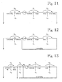
- Figure 3 shows an enhanced embodiment of the inventive apparatus with multiple independently-controllable electrodes.
- elements with reference numerals less than 200 have been described in connection with Figures 1 and 2 , and a repeated description is omitted.
- This embodiment comprises multiple independently-controllable electrodes 206A, 206B and 206C, of which three are shown but this number is purely arbitrary.
- Reference numeral 216 denotes an implementation of a controller which controls a switch matrix 217 which provides the high-voltage signal OUT to the electrodes 206A, 206B and 206C under control of the controller 216.
- the controller 216 may be responsive to commands from an external device, such as a data processing equipment (not shown separately).
- a benefit of the embodiment shown in Figure 3 is that virtually all the drive circuitry, including the high-voltage amplifier 100, controller 216, and switch matrix 217, can be integrated into a common enclosure which is denoted by reference numeral 200.
- the electrodes 206A, 206B and 206C and a single connecting wire for each electrode are outside the enclosure 200.
- the electrodes need to be nothing more than simple conducting or semi-conducting plates covered by appropriate insulators. Therefore the enclosure 200 can be positioned in virtually any convenient position because the only elements external to it are very simple electrodes and connecting wires (and, in some implementations a power supply, not shown separately).
- Some prior art systems provide direct stimulation of nerves via galvanic current conduction to the outermost layer of the skin. Because of the galvanic current conduction, such systems require two electrodes to stimulate an area of skin.
- the embodiment described in connection with Figure 3 involves multiple electrodes 206A, 206B and 206C, but each electrode alone stimulates a distinct area of skin, or more precisely, the mechanoreceptors, including the Pacinian corpuscles underlying the outermost layers of skin. Therefore a configuration of n electrodes conveys n bits of information in parallel.
- FIG 4 shows a specific implementation of the embodiment shown in Figure 3 .
- the switch matrix 217 comprises a bank of triacs 207A, 207B and 207C, but other types of semiconductor switches can be used, including semiconductor relays. Conventional electromechanical relays can be used as well.
- the switches (triacs) 207A, 207B and 207C are positioned logically after the transformer 104, ie, in the high-voltage circuitry.
- This implementation requires high-voltage switches (several hundred volts or several kilovolts) but it provides the benefit that the remainder of the circuitry, including the elements 100 through 114, can serve all of the electrodes 206A, 206B and 206C.
- the controller 216 may be connectable to a data processing equipment, an example of which is shown here as a personal computer PC.
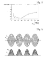
- Figure 5 is a graph which schematically illustrates the sensitivity of a randomly selected test subject to sensations produced by an apparatus substantially similar to the one shown in Figure 2 .
- the x-axis of the graph shows frequency of the low-frequency signal (item 114 in Figure 2 ) multiplied by two, while the y-axis shows the amplitude required to detect an electrosensory stimulation.
- the amplitude scale is relative.
- the small dip at 75 Hz may be a measurement anomaly.
- the reason for placing the doubled low-frequency signal on the x-axis is that the Coulomb forces between the electrode 106 and the body member 120 have two intensity peaks for each cycle of a sinusoidal low-frequency signal, as will be schematically illustrated in connection with Figure 6 .
- Reference document 1 relates to vibrotactile (mechanical) stimulation of skin, but the similarity of the frequency response shown in Figure 5 to the one published in Reference 1 suggests that the present CEI operates such that the electrode 106 and the sensitive member 120 (see Figure 1 ) form a capacitor over the insulator 108, and in that capacitor the oscillating Coulomb forces are converted to mechanical vibrations which are sensed by mechanoreceptors, including the Pacinian corpuscles.
- the inventors have also studied an alternative hypothesis wherein the Pacinian corpuscles are stimulated by current flowing through them, but this hypothesis does not explain the observations as well as the one which is based on Coulomb forces acting on the Pacinian corpuscles.
- the technical CEI described herein does not depend on the correctness of any particular hypothesis attempting to explain why the CEI operates the way it does.
- Figure 6 is a graph which further clarifies the operating principle of the CEI and the interpretation of frequencies in connection with the present CEI.
- Reference numeral 61 denotes the low-frequency input signal to the modulator 110 (shown as item 114 in Figure 2 ).
- Reference numeral 62 denotes the output of the modulator, ie, the high-frequency input signal as modulated by the low-frequency input signal.
- Reference numerals 63 and 64 denote the resulting Coulomb forces in the capacitive coupling between the electrode 106 and the body member 120 over the insulator 108. Because the two sides of the capacitive coupling have opposite charges, the Coulomb force between the two sides is always attractive and proportional to the square of the voltage.
- Reference numeral 63 denotes the actual Coulomb force while reference numeral 64 denotes its envelope.
- the envelope 64 is within the range of frequencies to which the Pacinian corpuscles are sensitive, but because the Coulomb force is always attractive, the envelope 64 has two peaks for each cycle of the modulator output signal 62, whereby a frequency-doubling effect is produced. Because the Coulomb force is proportional to the square of the voltage, any exemplary voltages disclosed herein should be interpreted as effective (RMS) values in case the voltages are not sinusoidal.
- the CEI can be implemented as part of an input/output peripheral device which is connectable to a data processing equipment.
- the data processing equipment can provide prompting and/or feedback via electrically-controllable electrosensory sensation.
- Figures 7A and 7B show implementations of the CEI wherein the strength of the capacitive coupling is adjusted by electrode movement. Generation of the electric field, and its variation as necessary, is effected via a set of electrodes 704 which comprises individual electrodes 703.
- the individual electrodes 703 are preferably individually controllable, wherein the controlling of an electrode affects its orientation and/or protrusion.
- Figure 7A shows an implementation wherein a group of electrodes 703 are oriented, via the output signal from the controller 216, such that the electrodes 703 collectively form a plane under the insulator 702.
- the high-voltage current (DC or AC) from the high-voltage amplifier 100 to the electrodes 703 generates an opposite-signed charge of sufficient strength to a body member (eg the finger 120) in close proximity to the apparatus.
- a capacitive coupling between the body member and the apparatus is formed over the insulator 702, which may give rise to a sensory stimulus.
- Figure 7B shows the same apparatus shown in Figure 7A , but in this case the strength of the capacitive coupling generated with the current from the high-voltage amplifier 100 is minimized by orienting the electrodes (now shown by reference numeral 714) such that they do not form a plane under the insulator 702.
- the electric field alternating with a low frequency can be generated by alternating the state of the apparatus between the two states shown in Figures 7A and 7B .
- the frequency of the state alternation can be in the order of several hundred, eg 200 to 300 full cycles per second.
- FIG 8 shows an implementation of the CEI wherein the individual electrodes 803 in the set of electrodes 804 may have charges of opposite signs.
- the charges of individual electrodes 803 may be adjusted and controlled via the controller 216.
- the individual electrodes 803 may be separated by insulator elements 806, so as the prevent sparking or shorting between the electrodes.
- the capacitive coupling between the CEI and the body member proximate to it may give rise to areas having charges with opposite signs 801. Such opposing charges are mutually attractive to one another.
- Coulomb forces stimulating the Pacinian corpuscles may be generated not only between the CEI and the body member but between infinitesimal areas within the body member itself.
- Figure 9 shows an implementation of the CEI wherein a group of individually controllable electrodes 910a through 910i are organized in the form of a matrix.
- a matrix can be integrated into a touch screen device, for example.
- the electrodes of the CEI apparatus can be positioned behind the touch screen, wherein "behind" means the side of the touch screen opposite to the side facing the user during normal operation.
- the electrodes can be very thin and/or transparent, whereby the electrodes can overlay the touch screen on the side normally facing the user.
- the controller 216 may control the switches in the switch array individually, or certain groups may form commonly-controllable groups.
- the surface of an individual electrode and/or its associated insulator can be specified according to the intended range of operations or applications. The minimum practical area is about 0.01 cm 2 , while the practical maximum is roughly equal to the size of a human hand. It is expected that surface areas between 0.1 and 1 cm 2 will be found most usable in practice.
- the matrix of electrodes 910a through 910i and the switch array 217 provide a spatial variation of the electro-sensory stimulation.
- the sensory stimulation provided to the user depends on the location of the user's body member, such as a finger, proximate to the CEI apparatus which is integrated to the inventive touch screen.
- the spatially varying sensory stimulation provides the user with an indication of the layout of the touch-sensitive areas of the touch screen interface.
- the controller 216 may direct the switch array 217 to produce a temporally varying (time-dependent) electro-sensory stimulation, which can be used for a wide variety of useful effects.
- the temporally varying electro-sensory stimulation can be used to indicate a detected activation of a touch-sensitive area ("key press").
- key press a touch-sensitive area
- This embodiment address a common problem associated with prior art touch screen devices, namely the fact that a detection of a key press produces no tactile feedback.
- Prior art application-level programs used via touch screen devices may provide visual or aural feedback, but such types of feedback exhibit the various problems described earlier.
- production of the visual or aural feedback from the application-level program causes a burden on the programming and execution of those programs.
- an interface-level or driver-level program provides a tactile feedback from a detected activation of a touch-sensitive area by using the temporally and spatially variant electro-sensory stimulation
- such interface-level or driver-level programs can be used by any application-level programs.
- the application-level programs can be coupled to the inventive touch screen interface via an application programming interface ("API") whose set of available functions includes the feedback generation described above.
- API application programming interface
- the temporally and spatially variant electro-sensory stimulation can also be used to change the layout of the touch-sensitive areas "on the fly". In hindsight, this operation may be considered roughly analogous to changing the keyboard or keypad layout depending on the application program or user interface screen currently executed. However, when prior art touch screen devices change keyboard or keypad layout on the fly, the new layout must be somehow indicated to the user, and this normally requires that the user sees the touch screen device.
- Some embodiments of the inventive touch screen device eliminate the need to see the touch screen device, assuming that the layout of the touch-sensitive areas is sufficiently simple. For instance, up to about two dozen different “key legends” can be indicated to the user by providing different patterns for the temporally and spatially variant electro-sensory stimulation.
- key legend refers to the fact that prior art touch screen devices, which produce no tactile feedback, normally produce visual cues, and these are commonly called “legends”.
- the function of the key legends can be provided via different patterns.
- the following patterns can be identified with one fingertip: pulses with low, medium or high repetition rate; sweeps to left, right, up or down, each with a few different repetition rates; rotations clockwise or anti-clockwise, each with a few different repetition rates.
- the inventive electro-sensory interface can produce a large number of different touch-sensitive areas, each with a distinct "feel" (technically: a different pattern for the temporal and spatial variation of the electro-sensory stimulus).
- touch device interface should be interpreted as an interface device which, among other things, is suitable for applications commonly associated with touch screen devices, although the presence of the screen is not mandatory.
- the strength of the capacitive coupling between the inventive CEI and a body member of its user can be determined by direct or indirect measurements.
- This measurement information can be utilized in various ways.
- the strength of the capacitive coupling can indicate the body member's proximity to the electrode, or it can indicate touching the electrode by the body member.
- Such measurement functionality can be provided by a dedicated measurement unit (not shown) or it can be integrated into one of the blocks described earlier, such as the switch matrix 217.
- the switch matrix 217 (or the optional dedicated measurement unit) can send the measurement information to the controller 216 which can utilize it to vary the electric fields generated by the electrodes, by varying the voltage or frequency.
- the controller 216 may forward the measurement information, or some information processed from it, to a data processing equipment, such as the personal computer PC shown in Figure 4 .
- inventive touch device interfaces can be interconnected via some communication network(s) and data processing equipment.
- the electro-sensory stimulation provided to the users of the touch screen devices may be based on some function of all users' contribution to the proximity to their respective devices.
- such an interconnection of two (or more) touch screen devices can provide their users with tactile feedback whose strength depends on the sum of the areas of hands touch the touch-sensitive areas. This technique simulates a handshake whose strength reflects the sum of hand pressure exerted by both (or all) users.
- a music teacher might "sense" how a remotely located student presses the keys of a simulated piano keyboard.
- Figures 10 through 13 are equivalent circuits (theoretical models) which may be useful in dimensioning the parameters of the capacitive coupling.
- Figure 10 illustrates distribution of an electric field-generating potential in capacitive couplings when the apparatus is grounded. The underlying theory is omitted here, and it suffices to say that in the arrangement shown in Figure 10 , the drive voltage e of an electrode is divided based on the ratio of capacitances C1 and C2, wherein C1 is the capacitance between the finger and the electrode and C2 is the stray capacitance of the user.
- the electric field experienced by the finger is caused by voltage U1:
- U 1 C 2 C 1 + C 2 ⁇ e
- This voltage is lower than the drive voltage e from the voltage source.
- the reference potential of the apparatus may be floating, as will be shown in Figure 11 . This arrangement further decreases the electric field directed to the body member, such as finger.
- some embodiments of the invention aim at keeping the capacitance C1 low in comparison to that of C2. At least capacitance C1 should not be significantly higher than C2. Some embodiments aim at adjusting or controlling C2, for instance by coupling the reference potential of the apparatus back to the user, as shown in Figure 12 .
- capacitance C1 can be treated as a capacitance consisting of three series-coupled partial capacitances: C i of the insulator material, C a of the air gap between insulator and finger, and C s formed by the outmost skin layer that is electrically insulating the inner, conducting tissue from the environment.
- C i of the insulator material
- C a of the air gap between insulator and finger
- C s formed by the outmost skin layer that is electrically insulating the inner, conducting tissue from the environment.
- ⁇ is the permittivity (dielectric constant) of the insulating material
- S is the (effective) surface area
- d is the distance between the surfaces of the capacitor.
- C1 is small and mainly determined by the air gap, C a .
- the effective air gap is small (approximately the height ridges of the fingerprint profile on the skin surface).
- the effectiveness of the electro-sensory stimulus generation can be enhanced by appropriate selection of insulator material, particularly in terms of thickness and dielectric properties. For instance, selecting a material with a relatively high dielectric constant for the insulator reduces the electric field in the material but increases the electric field strength in the air gap and skin.
- the effectiveness of the electro-sensory stimulus generation can be enhanced by optimal selection of the material that will be touched by the body member. This is particularly significant in connection with insulators which are good volume insulators (insulators in the direction of the surface's normal) but less so in the direction along the surface.
- An insulator's insulation capability along the surface may be negatively affected by surface impurities or moisture which have a negative effect on the apparent strength of the sensation felt by the body member to be stimulated.
- glass is generally considered a good insulator, but its surface tends to collect a thin sheet of moisture from the air. If the electrode of the CEI is insulated with glass, the electro-sensory effect is felt in close proximity (when there is still an air gap between body member and the glass surface). However, when the glass surface is touched, even lightly, the electro-sensory tends to weaken or disappear altogether. Coating the outer insulating surface with a material having a low surface conductance remedies such problems.
- the inventors speculate that if the surface having some surface conductivity is touched, it is the conductive layer on the surface that experiences the coulomb force rather than the body member touching the surface. Instead the touching body member acts as a kind of grounding for the conductive surface layer, for example via the stray capacitance of the body.
- stray capacitances can be controlled by arrangements in which several electrodes are used to generate potential differences among different areas of the touch screen surface.
- this technique can be implemented by arranging the touch-sensitive surface of a hand-held device (eg the top side of the device) to a first potential, while the opposite side is arranged to a second potential, wherein the two different potentials can be the positive and negative poles of the device.
- a first surface area can be the electric ground (reference potential), while a second surface area is charged to a high potential.
- insulator layer(s) it is possible to form minuscule areas of different potentials, such as potentials with opposite signs or widely different magnitudes, wherein the areas are small enough that the user's body member, such as finger, is simultaneously subjected to the electric fields from several areas with different potentials.
- FIG 13 shows an embodiment in which the capacitive coupling is utilized to detect touching or approaching by the user's body member, such as finger.
- a detected touching or approaching by the user's body member can be passed as an input to a data processing device.
- the voltage source is floating.
- a floating voltage source can be implemented, via inductive or capacitive coupling and/or with break-before-make switches.
- a secondary winding of a transformer is an example of a simple yet effective floating voltage source.
- the change in capacitance(s) can be detected on the primary side as well, for example as a change in load impedance. Such a change in capacitance(s) serves as an indication of a touching or approaching body member.
- the apparatus is arranged to utilize such indication of the touching or approaching body member such that the apparatus uses a first (lower) voltage to detect the touching or approaching by the body member and a second (higher) voltage to provide feedback to the user.
- a first (lower) voltage to detect the touching or approaching by the body member
- a second (higher) voltage to provide feedback to the user.
- feedback can indicate any of the following: the outline of the/each touch-sensitive area, a detection of the touching or approaching body member by the apparatus, the significance of (the act to be initiated by) the touch-sensitive area, or any other information processed by the application program and which is potentially useful to the user.
- Figure 14 schematically illustrates an embodiment in which a single electrode and temporal variations in the intensity of the electro-sensory stimulus can be used to create illusions of a textured touch screen surface.
- Reference numeral 1400 denotes a touch-sensitive screen which, for the purposes of describing the present embodiment, comprises three touch-sensitive areas A 1 , A 2 and A 3 . The approaching or touching by the touch-sensitive areas A 1 , A 2 and A 3 of a user's finger 120 is detected by a controller 1406.
- a conventional touch-sensitive screen 1400 can be complemented by an interface device according to the invention.
- Reference numeral 1404 denotes an electrode which is an implementation of the electrodes described in connection with previously-described embodiments, such as the electrode 106 described in connection with Figures 1 and 2 .
- a supplemental insulator 1402 may be positioned between the touch-sensitive screen 1400 and the inventive electrode 1404, in case the touch-sensitive screen 1400 itself fails to provide sufficient insulation.
- the controller 1406 uses information of the position of the finger 120 to temporally vary the intensity of the electro-sensory stimulation invoked by the electrode 1404 on the finger 120.
- the intensity of the electro-sensory stimulation is varied over time, time is not an independent variable in the present embodiment. Instead, timing of the temporal variations is a function of the position of the finger 120 relative to the touch-sensitive areas (here: A 1 , A 2 and A 3 ).
- the present embodiment is operable to cause variations in the intensity of the electro-sensory stimulation invoked by the electrode 1404 on the finger 120, wherein the variations are based on the position of the finger 120 relative to the touch-sensitive areas.
- the bottom side of Figure 14 illustrates this functionality.
- the three touch-sensitive area A 1 , A 2 and A 3 are demarcated by respective x coordinate pairs ⁇ x 1 , x 2 ⁇ , ⁇ x 3 , x 4 ⁇ and ⁇ x 5 , x 7 ⁇ . Processing in the y direction is analogous and a detailed description is omitted.
- the controller 1406 does not sense the presence of the finger, or senses the finger as inactive, as long as the finger is to the left of any of the touch-sensitive areas A 1 , A 2 and A 3 . In this example the controller 1406 responds by applying a low-intensity signal to the electrode 1404.
- the controller 1406 detects the finger over the first touch-sensitive area A 1 and starts to apply a medium-intensity signal to the electrode 1404. Between the areas A 1 and A 2 (between x coordinates x 2 and x 3 ), the controller again applies a low-intensity signal to the electrode 1404.
- the second touch-sensitive area A 2 is processed similarly to the first touch-sensitive area A 1 , but the third touch-sensitive area A 3 is processed somewhat differently.
- the controller 1406 detects the finger 120 above or in close proximity to the area A 3 , it begins to apply the medium-intensity signal to the electrode 1404, similarly to areas A 1 and A 2 .
- the controller 1406 detects the finger press (activation of the function assigned to the area A 3 ) and responds by applying a high-intensity signal to the electrode 1404.
- the embodiment shown in Figure 14 can provide the user with a tactile feedback which creates an illusion of a textures surface, although only a single electrode 1404 was used to create the electro-sensory stimulus.
- a residual problem is, however, that the user has to memorize the significance of the several touch-sensitive areas or obtain visual or aural information on their significance.
- Figure 15 shows a further enhanced embodiment from the one described in connection with Figure 14 .
- the embodiment shown in Figure 15 uses different temporal variations of the intensity of the electro-sensory stimulus, wherein the different temporal variations provide the user with a tactile feedback indicating the significance of the touch-sensitive areas.
- the controller here denoted by reference numeral 1506, applies different temporal variations to the intensity of the signal to the electrode 1404.
- the first touch-sensitive area A 1 is processed similarly to the preceding embodiment, or in other words, the intensity of the electro-sensory stimulus depends only on the presence of the finger 120 in close proximity to the area A 1 .
- the controller 1506 also applies temporal variations to the intensity of the electro-sensory stimulus.
- the significance (coarsely analogous with a displayed legend) of area A 2 is indicated by a pulsed electro-sensory stimulus at a first (low) repetition rate
- the significance of area A 3 is indicated by a pulsed electro-sensory stimulus at a second (higher) repetition rate.
- the three touch-sensitive areas A 1 , A 2 and A 3 can invoke the three functions in a yes/no/cancel -type user interface, wherein the user can sense the positions of the user interface keys (here: the three touch-sensitive areas) and the indication of an accepted input only via tactile feedback.
- the user needs no visual or aural information on the positions of the touch-sensitive areas or on the selected function.
- the embodiment described in connection with Figure 15 is particularly attractive in car navigators or the like, which should not require visual attention from their users.
- the embodiments shown in Figures 14 and 15 can be combined with the multi-electrode embodiment disclosed in connection with Figure 9 , such that the signal to each of several electrodes (shown in Figure 9 as items 910a through 910i) is controlled individually.
Claims (16)
- Vorrichtung zur Erzeugung einer elektrosensorischen Empfindung in wenigstens einem zu stimulierenden Körperteil (120), wobei die Vorrichtung Folgendes umfasst:- eine oder mehrere leitende Elektroden (106), wobei jede leitende Elektrode mit einem Isolator (108) bereitgestellt wird, wobei - wenn sich der wenigstens eine zu stimulierende Körperteil (120) benachbart zur leitenden Elektrode befindet - der Isolator das Fließen von Gleichstrom von der leitenden Elektrode zu dem zu stimulierenden Körperteil verhindert und eine kapazitive Kopplung zwischen der leitenden Elektrode (106) und dem wenigstens einen zu stimulierenden Körperteil (120) über den Isolator (108) gebildet wird;- eine Hochspannungsquelle (100, 102, 104) zum Einspeisen einer elektrischen Eingabe (OUT) in die eine oder die mehreren leitenden Elektroden, wobei die elektrische Eingabe wenigstens einen Teil ihrer Energie in einem Frequenzbereich zwischen 10 Hz und 1000 Hz aufweist;- wobei die kapazitive Kopplung und die elektrische Eingabe zum Erzeugen einer elektrosensorischen Empfindung ausgelegt sind; und- wobei die elektrosensorische Empfindung unabhängig von irgendeiner mechanischen Vibration der einen oder der mehreren leitenden Elektroden (106) oder Isolatoren (108) erzeugt wird;gekennzeichnet durch eine Masseverbindung (210) zwischen:- einer Referenzspannung (REF) der Hochspannungsquelle (100, 102, 104), die sich von der elektrischen Eingabe (OUT) in die eine oder die mehreren leitenden Elektroden unterscheidet; und- wenigstens einer Masseelektrode (212), die von der einen oder den mehreren leitenden Elektroden (106) getrennt ist, wobei die Masseelektrode (212) so positioniert ist, dass sie von einem zweiten Körperteil (222) berührt wird, der von jedem des wenigstens einen zu stimulierenden Körperteils (120; 220A, 220B, 220C) verschieden ist.
- Vorrichtung nach Anspruch 1, wobei:- die kapazitive Kopplung und die elektrische Eingabe so ausgelegt sind, dass sie eine elektrosensorische Empfindung in dem wenigstens einen Körperteil produzieren, wenn sich der wenigstens eine Körperteil benachbart zu der einen oder zu den mehreren leitenden Elektroden befindet;- wobei die elektrosensorische Empfindung unabhängig von irgendeiner Berührung oder mechanischen Bewegung zwischen dem wenigstens einen Körperteil und der einen oder den mehreren leitenden Elektroden erzeugt wird.
- Vorrichtung nach einem der vorhergehenden Ansprüche, wobei die Vorrichtung eine leitende Elektrode für jeden räumlich gesonderten, zu stimulierenden Körperteil (120; 220A, 220B, 220C) umfasst.
- Vorrichtung nach einem der vorhergehenden Ansprüche, wobei die Vorrichtung eine leitende Elektrode (206A, 206B, 206C) für jeden von mehreren räumlich gesonderten, zu stimulierenden Körperteilen (220A, 220B, 220C) umfasst.
- Vorrichtung nach einem der vorhergehenden Ansprüche, wobei die Vorrichtung Mittel (116, 216) zur Vermittlung von Informationen über die elektrosensorische Empfindung durch Modulation der elektrischen Eingabe gemäß den Informationen umfasst.
- Vorrichtung nach einem der vorhergehenden Ansprüche, die weiterhin eine Verkleidung (200) umfasst, die die Hochspannungsquelle (100, 102, 104) enthält, welche allen von den mehreren leitenden Elektroden (206A, 206B, 206C) gemeinsam ist, und wobei die Verkleidung (200) ebenfalls Mittel (217) zur gleichzeitigen Vermittlung der elektrischen Eingabe (OUT) in null oder mehr der mehreren leitenden Elektroden unter Steuerung durch einen gemeinsamen Regler (216) umfasst.
- Vorrichtung nach Anspruch 6, wobei die Vorrichtung Bestandteil eines Eingabe-/Ausgabe-Peripheriegeräts ist, das mit einer Datenverarbeitungseinrichtung verbunden werden kann.
- Vorrichtung nach einem der vorhergehenden Ansprüche, die weiterhin Folgendes umfasst:- eine Oberfläche (1400), die so angeordnet ist, dass der zu stimulierende Körperteil (120) sie berührt oder sich ihr annähert, wobei die Oberfläche wenigstens eine berührungsempfindliche Fläche (A1, A2, A3) aufweist, wobei jede berührungsempfindliche Fläche eine vorbestimmte Position (x1-x2; x3-x4; x5-x7) aufweist;- wobei die Vorrichtung Mittel zum Zuordnen wenigstens einer Funktion zu der wenigstens einen berührungsempfindlichen Fläche umfasst oder betriebsfähig mit diesen verbunden werden kann; und- wobei die Vorrichtung weiterhin Mittel (1406, 1506) zum räumlichen und/oder zeitlichen Variieren der Intensität des elektrosensorischen Stimulus auf Basis einer detektierten Berührung oder Annäherung an die wenigstens eine berührungsempfindliche Fläche (A1, A2, A3) durch den zu stimulierenden Körperteil (120) umfasst;- wobei die Schnittstelleneinrichtung in der Lage ist, eine Rückmeldung an einen Nutzer über den zu stimulierenden Körperteil zu erzeugen.
- Vorrichtung nach Anspruch 8, wobei die Mittel (1406, 1506) zum räumlichen und/oder zeitlichen Variieren der Intensität des elektrosensorischen Stimulus Mittel (1406, 1506) zum zeitlichen Variieren der Intensität des elektrosensorischen Stimulus umfasst.
- Vorrichtung nach Anspruch 9, wobei:- die Mittel zum Zuordnen wenigstens einer Funktion dazu betrieben werden können, die wenigstens eine Funktion, die der wenigstens einen berührungsempfindlichen Fläche zugeordnet ist, dynamisch zu ändern; und- die Vorrichtung dazu betrieben werden kann, die Rückmeldung auf Basis der Funktion, die der wenigstens einen berührungsempfindlichen Fläche zugeordnet ist, zu variieren.
- Vorrichtung nach einem der vorhergehenden Ansprüche, wobei die elektrische Eingabe eine niederfrequente Komponente (114) in einem Frequenzbereich zwischen 10 Hz und 1000 Hz und eine hochfrequente Komponente (112), die eine Frequenz aufweist, die höher als die Frequenz der niederfrequenten Komponente (114) und niedriger als 500 kHz ist, umfasst.
- Vorrichtung nach Anspruch 11, die Mittel (110) zur Modulation der hochfrequenten Komponente (112) durch die niederfrequente Komponente (114) umfasst.
- Vorrichtung nach einem der vorhergehenden Ansprüche, wobei die elektrische Eingabe in die eine oder die mehreren leitenden Elektroden (106) eine Spitze-Spitze-Spannung von 750 bis 100.000 Volt aufweist.
- Vorrichtung nach einem der vorhergehenden Ansprüche, wobei der Isolator eine Stärke zwischen 0,1 mm und 50 mm aufweist.
- Vorrichtung nach einem der vorhergehenden Ansprüche, wobei wenigstens ein Isolator eine erste Schicht und eine zweite Schicht umfasst, so dass sich die erste Schicht näher an der leitenden Elektrode als die zweite Schicht befindet, und wobei die zweite Schicht eine geringere Oberflächenleitfähigkeit als die erste Schicht aufweist.
- Verfahren zum Verursachen einer elektrosensorischen Empfindung in wenigstens einem zu stimulierenden Körperteil (120), wobei das Verfahren Folgendes beinhaltet:- das Bereitstellen einer oder mehrerer leitender Elektroden (106), wobei jede leitende Elektrode mit einem Isolator (108) bereitgestellt wird, wobei - wenn sich der wenigstens eine zu stimulierende Körperteil (120) benachbart zu der leitenden Elektrode befindet - der Isolator das Fließen von Gleichstrom von der leitenden Elektrode zu dem zu stimulierenden Körperteil verhindert und eine kapazitive Kopplung zwischen der leitenden Elektrode (106) und dem zu stimulierenden Körperteil (120) über den Isolator (108) gebildet wird;- das Bereitstellen einer Hochspannungsquelle (100, 102, 104) zum Einspeisen einer elektrischen Eingabe (OUT) in die eine oder die mehreren leitenden Elektroden, wobei die elektrische Eingabe wenigstens einen Teil ihrer Energie in einem Frequenzbereich zwischen 10 Hz und 1000 Hz aufweist;- wobei die kapazitive Kopplung und die elektrische Eingabe zum Erzeugen einer elektrosensorischen Empfindung ausgelegt sind; und- wobei die elektrosensorische Empfindung unabhängig von irgendeiner mechanischen Vibration der einen oder der mehreren leitenden Elektroden (106) oder Isolatoren (108) erzeugt wird;gekennzeichnet durch das Bereitstellen einer Masseverbindung (210) zwischen:- einer Referenzspannung (REF) der Hochspannungsquelle (100, 102, 104), die sich von der elektrischen Eingabe (OUT) in die eine oder die mehreren leitenden Elektroden unterscheidet; und- wenigstens einer Masseelektrode (212), die von der einen oder den mehreren leitenden Elektroden (106) getrennt ist, wobei die Masseelektrode (212) so positioniert ist, dass sie von einem zweiten Körperteil (222) berührt wird, der von jedem des wenigstens einen zu stimulierenden Körperteils (120; 220A, 220B, 220C) verschieden ist.
Priority Applications (1)
| Application Number | Priority Date | Filing Date | Title |
|---|---|---|---|
| EP14169239.2A EP2790088B1 (de) | 2007-09-18 | 2008-09-17 | Verfahren und Vorrichtung zur sensorischen Stimulation |
Applications Claiming Priority (5)
| Application Number | Priority Date | Filing Date | Title |
|---|---|---|---|
| FI20075651A FI121403B (fi) | 2007-09-18 | 2007-09-18 | Sensorinen liitäntä |
| FI20080213A FI20080213L (fi) | 2007-09-18 | 2008-03-14 | Menetelmä ja laite aistien stimuloimiseksi |
| FI20085472A FI20085472A0 (fi) | 2008-05-19 | 2008-05-19 | Menetelmä ja laite aististimulointia varten |
| FI20085475A FI20085475A0 (fi) | 2008-05-19 | 2008-05-19 | Kosketuslaiteliitäntä |
| PCT/FI2008/050514 WO2009037379A1 (en) | 2007-09-18 | 2008-09-17 | Method and apparatus for sensory stimulation |
Related Child Applications (2)
| Application Number | Title | Priority Date | Filing Date |
|---|---|---|---|
| EP14169239.2A Division EP2790088B1 (de) | 2007-09-18 | 2008-09-17 | Verfahren und Vorrichtung zur sensorischen Stimulation |
| EP14169239.2A Division-Into EP2790088B1 (de) | 2007-09-18 | 2008-09-17 | Verfahren und Vorrichtung zur sensorischen Stimulation |
Publications (3)
| Publication Number | Publication Date |
|---|---|
| EP2203797A1 EP2203797A1 (de) | 2010-07-07 |
| EP2203797A4 EP2203797A4 (de) | 2011-12-07 |
| EP2203797B1 true EP2203797B1 (de) | 2014-07-09 |
Family
ID=40467548
Family Applications (2)
| Application Number | Title | Priority Date | Filing Date |
|---|---|---|---|
| EP08805437.4A Not-in-force EP2203797B1 (de) | 2007-09-18 | 2008-09-17 | Verfahren und vorrichtung zur sensorischen stimulation |
| EP14169239.2A Not-in-force EP2790088B1 (de) | 2007-09-18 | 2008-09-17 | Verfahren und Vorrichtung zur sensorischen Stimulation |
Family Applications After (1)
| Application Number | Title | Priority Date | Filing Date |
|---|---|---|---|
| EP14169239.2A Not-in-force EP2790088B1 (de) | 2007-09-18 | 2008-09-17 | Verfahren und Vorrichtung zur sensorischen Stimulation |
Country Status (6)
| Country | Link |
|---|---|
| US (6) | US7924144B2 (de) |
| EP (2) | EP2203797B1 (de) |
| JP (1) | JP5305828B2 (de) |
| KR (1) | KR101580227B1 (de) |
| CN (2) | CN103513764B (de) |
| WO (1) | WO2009037379A1 (de) |
Cited By (2)
| Publication number | Priority date | Publication date | Assignee | Title |
|---|---|---|---|---|
| US11484263B2 (en) | 2017-10-23 | 2022-11-01 | Datafeel Inc. | Communication devices, methods, and systems |
| US11934583B2 (en) | 2020-10-30 | 2024-03-19 | Datafeel Inc. | Wearable data communication apparatus, kits, methods, and systems |
Families Citing this family (132)
| Publication number | Priority date | Publication date | Assignee | Title |
|---|---|---|---|---|
| US20100312129A1 (en) | 2005-01-26 | 2010-12-09 | Schecter Stuart O | Cardiovascular haptic handle system |
| WO2007111909A2 (en) * | 2006-03-24 | 2007-10-04 | Northwestern University | Haptic device with indirect haptic feedback |
| FI20085475A0 (fi) | 2008-05-19 | 2008-05-19 | Senseg Oy | Kosketuslaiteliitäntä |
| CN103513764B (zh) | 2007-09-18 | 2017-04-26 | 森赛格公司 | 用于感觉刺激的方法和设备 |
| JP2010086471A (ja) * | 2008-10-02 | 2010-04-15 | Sony Corp | 操作感提供装置、および操作感フィードバック方法、並びにプログラム |
| WO2010037894A1 (en) | 2008-10-03 | 2010-04-08 | Senseg Oy | Techniques for presenting vehicle-related information |
| GB2464117B (en) * | 2008-10-03 | 2015-01-28 | Hiwave Technologies Uk Ltd | Touch sensitive device |
| US8805517B2 (en) | 2008-12-11 | 2014-08-12 | Nokia Corporation | Apparatus for providing nerve stimulation and related methods |
| US8686951B2 (en) | 2009-03-18 | 2014-04-01 | HJ Laboratories, LLC | Providing an elevated and texturized display in an electronic device |
| GB0905692D0 (en) * | 2009-04-02 | 2009-05-20 | Tno | Touch sensitive device |
| DE102009020796B3 (de) * | 2009-04-30 | 2010-07-29 | Technische Universität Dresden | Vorrichtung zur Verarbeitung und Wiedergabe von Signalen in elektronischen Systemen zur elektrotaktilen Stimulation |
| US8115499B2 (en) | 2009-05-22 | 2012-02-14 | Freescale Semiconductor, Inc. | Device with proximity detection capability |
| KR101600851B1 (ko) * | 2009-05-22 | 2016-03-08 | 엘지전자 주식회사 | 이동단말기 및 그 제어방법 |
| CN101907922B (zh) * | 2009-06-04 | 2015-02-04 | 新励科技(深圳)有限公司 | 一种触感触控系统 |
| US9372536B2 (en) * | 2009-06-05 | 2016-06-21 | Empire Technology Development Llc | Touch screen with tactile feedback |
| US8909683B1 (en) | 2009-07-17 | 2014-12-09 | Open Invention Network, Llc | Method and system for communicating with internet resources to identify and supply content for webpage construction |
| KR101962081B1 (ko) | 2009-07-22 | 2019-03-25 | 임머숀 코퍼레이션 | 제어 제스처의 입력 동안에 가상 장비의 제어에 관한 복합 햅틱 자극을 제공하기 위한 시스템 및 방법 |
| US8441465B2 (en) | 2009-08-17 | 2013-05-14 | Nokia Corporation | Apparatus comprising an optically transparent sheet and related methods |
| JP2011048685A (ja) * | 2009-08-27 | 2011-03-10 | Kyocera Corp | 入力装置 |
| JP2011048606A (ja) * | 2009-08-27 | 2011-03-10 | Kyocera Corp | 入力装置 |
| US8779307B2 (en) | 2009-10-05 | 2014-07-15 | Nokia Corporation | Generating perceptible touch stimulus |
| US8766933B2 (en) * | 2009-11-12 | 2014-07-01 | Senseg Ltd. | Tactile stimulation apparatus having a composite section comprising a semiconducting material |
| US20110109584A1 (en) * | 2009-11-12 | 2011-05-12 | Jukka Linjama | Tactile stimulation apparatus having a composite section comprising a semiconducting material |
| US8552846B2 (en) | 2010-01-22 | 2013-10-08 | Vision Tactil Portable, S.L. | Method and apparatus for driving a dielectric elastomer matrix avoiding crosstalk |
| WO2011089296A1 (es) * | 2010-01-22 | 2011-07-28 | Visión Táctil Portable, S.L. | Sistema de visión táctil portable y dispositivo de estimulacion táctil para el mismo. |
| US20110199342A1 (en) | 2010-02-16 | 2011-08-18 | Harry Vartanian | Apparatus and method for providing elevated, indented or texturized sensations to an object near a display device or input detection using ultrasound |
| TW201203041A (en) | 2010-03-05 | 2012-01-16 | Canatu Oy | A touch sensitive film and a touch sensing device |
| US9645996B1 (en) | 2010-03-25 | 2017-05-09 | Open Invention Network Llc | Method and device for automatically generating a tag from a conversation in a social networking website |
| US8791800B2 (en) | 2010-05-12 | 2014-07-29 | Nokia Corporation | Detecting touch input and generating perceptible touch stimulus |
| US20110285517A1 (en) * | 2010-05-18 | 2011-11-24 | Tai-Seng Lam | Terminal apparatus and vibration notification method thereof |
| US9579690B2 (en) | 2010-05-20 | 2017-02-28 | Nokia Technologies Oy | Generating perceptible touch stimulus |
| US9367150B2 (en) * | 2010-05-20 | 2016-06-14 | Nokia Technologies Oy | Apparatus and associated methods |
| US20120327006A1 (en) * | 2010-05-21 | 2012-12-27 | Disney Enterprises, Inc. | Using tactile feedback to provide spatial awareness |
| US20110285666A1 (en) * | 2010-05-21 | 2011-11-24 | Ivan Poupyrev | Electrovibration for touch surfaces |
| JP2012034157A (ja) * | 2010-07-30 | 2012-02-16 | Sony Corp | 通信装置並びに通信システム |
| CN102427354B (zh) * | 2010-08-12 | 2014-12-10 | 鲍臻 | 具有电流模拟触感反馈的按键开关以及触敏显示器 |
| US9110507B2 (en) | 2010-08-13 | 2015-08-18 | Nokia Technologies Oy | Generating perceptible touch stimulus |
| DE102010047261B4 (de) * | 2010-10-01 | 2013-04-25 | Trw Automotive Electronics & Components Gmbh | Schaltvorrichtung |
| US9746968B1 (en) | 2010-11-10 | 2017-08-29 | Open Invention Network Llc | Touch screen display with tactile feedback using transparent actuator assemblies |
| US9030050B1 (en) * | 2010-11-26 | 2015-05-12 | Senseg Ltd. | Voltage amplifier |
| US8854319B1 (en) * | 2011-01-07 | 2014-10-07 | Maxim Integrated Products, Inc. | Method and apparatus for generating piezoelectric transducer excitation waveforms using a boost converter |
| US8942828B1 (en) | 2011-04-13 | 2015-01-27 | Stuart Schecter, LLC | Minimally invasive cardiovascular support system with true haptic coupling |
| US9448713B2 (en) * | 2011-04-22 | 2016-09-20 | Immersion Corporation | Electro-vibrotactile display |
| US10108288B2 (en) | 2011-05-10 | 2018-10-23 | Northwestern University | Touch interface device and method for applying controllable shear forces to a human appendage |
| US9122325B2 (en) | 2011-05-10 | 2015-09-01 | Northwestern University | Touch interface device and method for applying controllable shear forces to a human appendage |
| CN102208144B (zh) * | 2011-05-24 | 2015-10-28 | 中兴通讯股份有限公司 | 屏幕触感功能的实现方法及装置 |
| TWI431516B (zh) | 2011-06-21 | 2014-03-21 | Quanta Comp Inc | 觸覺回饋方法及其電子裝置 |
| EP2754008A4 (de) | 2011-06-21 | 2015-04-22 | Univ Northwestern | Berührungsschnittstellenvorrichtung und verfahren zum anwenden von querkräften auf menschliche gliedmassen |
| KR101891858B1 (ko) | 2011-09-06 | 2018-08-24 | 임머숀 코퍼레이션 | 햅틱 출력 장치 및 햅틱 출력 장치에서 햅틱 효과를 생성하는 방법 |
| JP2013058153A (ja) * | 2011-09-09 | 2013-03-28 | Alps Electric Co Ltd | 触覚刺激発生装置 |
| US9733706B2 (en) * | 2011-10-26 | 2017-08-15 | Nokia Technologies Oy | Apparatus and associated methods for touchscreen displays |
| US9495010B2 (en) | 2011-10-26 | 2016-11-15 | Nokia Technologies Oy | Apparatus and associated methods |
| US9195350B2 (en) | 2011-10-26 | 2015-11-24 | Nokia Technologies Oy | Apparatus and associated methods |
| US8922507B2 (en) | 2011-11-17 | 2014-12-30 | Google Inc. | Providing information through tactile feedback |
| TWI447631B (zh) * | 2011-12-07 | 2014-08-01 | Ind Tech Res Inst | 投射式電容觸控裝置及其觸控面板的觸控方法 |
| US8711118B2 (en) | 2012-02-15 | 2014-04-29 | Immersion Corporation | Interactivity model for shared feedback on mobile devices |
| US8493354B1 (en) | 2012-08-23 | 2013-07-23 | Immersion Corporation | Interactivity model for shared feedback on mobile devices |
| KR101960842B1 (ko) * | 2012-04-04 | 2019-07-15 | 삼성전자주식회사 | 밀착형 촉각 전달 장치 및 밀착형 촉각 전달 장치의 동작 방법 |
| WO2015127257A1 (en) | 2014-02-21 | 2015-08-27 | Northwestern University | Haptic display with simultaneous sensing and actuation |
| US8570296B2 (en) | 2012-05-16 | 2013-10-29 | Immersion Corporation | System and method for display of multiple data channels on a single haptic display |
| US10013082B2 (en) | 2012-06-05 | 2018-07-03 | Stuart Schecter, LLC | Operating system with haptic interface for minimally invasive, hand-held surgical instrument |
| TWI470491B (zh) | 2012-06-19 | 2015-01-21 | Ind Tech Res Inst | 觸覺回饋裝置 |
| JP6076342B2 (ja) * | 2012-06-25 | 2017-02-08 | センセグ オサケ ユキチュア | 触覚センサ用前面板 |
| DE102012211163A1 (de) * | 2012-06-28 | 2014-06-26 | Bayerische Motoren Werke Aktiengesellschaft | Verfahren zum Empfangen einer Eingabe auf einem berührungsempfindlichen Feld |
| JP6037146B2 (ja) * | 2012-06-29 | 2016-11-30 | パナソニックIpマネジメント株式会社 | 触感提示機能つきタッチパネル装置 |
| JP5875074B2 (ja) * | 2012-09-05 | 2016-03-02 | アルプス電気株式会社 | 触覚刺激発生装置および座標入力システム |
| CN103677256B (zh) * | 2012-09-12 | 2018-05-01 | 三星显示有限公司 | 呈现触觉图像的方法和用于执行该方法的触摸屏设备 |
| JP6071372B2 (ja) | 2012-09-21 | 2017-02-01 | キヤノン株式会社 | 電子機器及び電子機器の制御方法 |
| US8743072B2 (en) * | 2012-09-28 | 2014-06-03 | Lg Electronics Inc. | Display device and control method thereof |
| US9196134B2 (en) | 2012-10-31 | 2015-11-24 | Immersion Corporation | Method and apparatus for simulating surface features on a user interface with haptic effects |
| US9122330B2 (en) * | 2012-11-19 | 2015-09-01 | Disney Enterprises, Inc. | Controlling a user's tactile perception in a dynamic physical environment |
| US9330544B2 (en) | 2012-11-20 | 2016-05-03 | Immersion Corporation | System and method for simulated physical interactions with haptic effects |
| US9836150B2 (en) | 2012-11-20 | 2017-12-05 | Immersion Corporation | System and method for feedforward and feedback with haptic effects |
| CN102968214A (zh) * | 2012-11-27 | 2013-03-13 | 上海华勤通讯技术有限公司 | 触控终端及其使用方法 |
| CN103034331B (zh) * | 2012-12-12 | 2016-06-29 | 中兴通讯股份有限公司 | 一种触觉反馈装置及终端 |
| CN103869952B (zh) * | 2012-12-17 | 2018-06-26 | 富泰华工业(深圳)有限公司 | 触感反馈系统及提供触感反馈的方法 |
| US9035894B2 (en) * | 2013-01-24 | 2015-05-19 | Industrial Technology Research Institute | Touch sensing and feedback apparatuses and methods |
| US9189098B2 (en) | 2013-03-14 | 2015-11-17 | Immersion Corporation | Systems and methods for syncing haptic feedback calls |
| KR102214929B1 (ko) | 2013-04-15 | 2021-02-10 | 삼성전자주식회사 | 촉각 제공 장치 및 방법 |
| US9939900B2 (en) | 2013-04-26 | 2018-04-10 | Immersion Corporation | System and method for a haptically-enabled deformable surface |
| US9519346B2 (en) | 2013-05-17 | 2016-12-13 | Immersion Corporation | Low-frequency effects haptic conversion system |
| US10120447B2 (en) | 2013-06-24 | 2018-11-06 | Northwestern University | Haptic display with simultaneous sensing and actuation |
| US9729730B2 (en) | 2013-07-02 | 2017-08-08 | Immersion Corporation | Systems and methods for perceptual normalization of haptic effects |
| TWI514196B (zh) | 2013-08-05 | 2015-12-21 | Ind Tech Res Inst | 觸覺回饋裝置 |
| US10108305B2 (en) | 2013-08-13 | 2018-10-23 | Samsung Electronics Company, Ltd. | Interaction sensing |
| US10042446B2 (en) | 2013-08-13 | 2018-08-07 | Samsung Electronics Company, Ltd. | Interaction modes for object-device interactions |
| JP6327466B2 (ja) * | 2013-10-10 | 2018-05-23 | Tianma Japan株式会社 | 触覚提示装置、電子機器、および触覚提示方法 |
| US9189932B2 (en) * | 2013-11-06 | 2015-11-17 | Andrew Kerdemelidis | Haptic notification apparatus and method |
| US9639158B2 (en) | 2013-11-26 | 2017-05-02 | Immersion Corporation | Systems and methods for generating friction and vibrotactile effects |
| JP5788474B2 (ja) * | 2013-12-06 | 2015-09-30 | コスモヘルス株式会社 | 体感パッド装置及び電位治療器 |
| JP6319328B2 (ja) * | 2014-02-14 | 2018-05-09 | 富士通株式会社 | 教育用触感提供装置、及び、システム |
| FR3018122A1 (fr) | 2014-02-28 | 2015-09-04 | Orange | Procede de controle d'acces par retour haptique |
| CN107077588A (zh) * | 2014-03-12 | 2017-08-18 | 艾戴克斯公司 | 指纹检测装置及其驱动方法 |
| CN105094347B (zh) * | 2014-05-06 | 2020-01-31 | 联想(北京)有限公司 | 键盘及其驱动方法、包括该键盘的电子设备 |
| KR101846256B1 (ko) | 2014-05-09 | 2018-05-18 | 삼성전자주식회사 | 필기감을 제공하는 촉각 피드백 장치 및 방법 |
| TWI503757B (zh) * | 2014-05-30 | 2015-10-11 | Image Match Desgin Inc | 指紋感測器 |
| US10031582B2 (en) * | 2014-06-05 | 2018-07-24 | Immersion Corporation | Systems and methods for induced electrostatic haptic effects |
| CN104063054B (zh) * | 2014-06-06 | 2017-02-15 | 南京航空航天大学 | 基于双向摩擦力控制的触觉再现装置及触觉再现方法 |
| US9696806B2 (en) * | 2014-07-02 | 2017-07-04 | Immersion Corporation | Systems and methods for multi-output electrostatic haptic effects |
| US9606624B2 (en) * | 2014-07-02 | 2017-03-28 | Immersion Corporation | Systems and methods for surface elements that provide electrostatic haptic effects |
| CN105446515A (zh) * | 2014-08-22 | 2016-03-30 | 联想(北京)有限公司 | 一种触控设备及包括触控设备的装置 |
| US9535550B2 (en) | 2014-11-25 | 2017-01-03 | Immersion Corporation | Systems and methods for deformation-based haptic effects |
| KR101554256B1 (ko) * | 2015-02-16 | 2015-09-18 | 박동현 | 햅틱 패턴을 이용한 시각 장애인용 문자 표시 방법, 이 방법이 적용된 터치스크린 및 이를 이용한 디스플레이 장치 |
| WO2016138539A1 (en) * | 2015-02-27 | 2016-09-01 | Tactual Labs Co. | Electrotactile feedback in multitouch systems |
| JP6386952B2 (ja) | 2015-03-18 | 2018-09-05 | アルプス電気株式会社 | 電子機器及び振動制御方法 |
| US10739853B2 (en) * | 2015-06-10 | 2020-08-11 | Northwestern University | Method and apparatus for finger position tracking and haptic display using conductive islands |
| US10705610B2 (en) | 2015-06-19 | 2020-07-07 | Northwestern University | Apparatus for unified audio tactile feedback |
| US9374061B1 (en) * | 2015-09-02 | 2016-06-21 | Resonant Inc. | Method of optimizing input impedance of surface acoustic wave filter |
| US9990078B2 (en) | 2015-12-11 | 2018-06-05 | Immersion Corporation | Systems and methods for position-based haptic effects |
| US9928696B2 (en) | 2015-12-30 | 2018-03-27 | Immersion Corporation | Externally-activated haptic devices and systems |
| US10631752B2 (en) * | 2016-01-27 | 2020-04-28 | Life Detection Technologies, Inc. | Systems and methods for detecting physical changes without physical contact |
| US10598388B2 (en) | 2016-04-07 | 2020-03-24 | Electrolux Home Products, Inc. | Appliance with electrovibration user feedback in a touch panel interface |
| US9983675B2 (en) | 2016-06-10 | 2018-05-29 | Immersion Corporation | Systems and methods for monitoring insulation integrity for electrostatic friction |
| US9886829B2 (en) | 2016-06-20 | 2018-02-06 | Immersion Corporation | Systems and methods for closed-loop control for haptic feedback |
| US9898904B1 (en) | 2016-08-17 | 2018-02-20 | Immersion Corporation | Selective control of an electric field to deliver a touchless haptic effect |
| US10234945B2 (en) | 2016-09-09 | 2019-03-19 | Immersion Corporation | Compensated haptic rendering for flexible electronic devices |
| US10261586B2 (en) | 2016-10-11 | 2019-04-16 | Immersion Corporation | Systems and methods for providing electrostatic haptic effects via a wearable or handheld device |
| US10534435B2 (en) | 2016-11-18 | 2020-01-14 | Immersion Corporation | Handheld interface device having a plurality of electrostatic friction (ESF) electrodes |
| US10416768B2 (en) | 2016-12-28 | 2019-09-17 | Immersion Corporation | Unitary sensor and haptic actuator |
| US9928700B1 (en) | 2017-01-25 | 2018-03-27 | Immersion Corporation | Method and apparatus for controlling generation of electrostatic friction effects for a plurality of electrodes |
| JP6819783B2 (ja) * | 2017-07-11 | 2021-01-27 | 富士通株式会社 | 駆動制御装置、電子機器、及び駆動制御方法 |
| US20210046308A1 (en) * | 2018-01-19 | 2021-02-18 | AMOSENSE Co.,Ltd | Apparatus and method for controlling output of skin care device |
| JP6888558B2 (ja) * | 2018-01-19 | 2021-06-16 | 豊田合成株式会社 | 触感提示装置 |
| DE102018202372A1 (de) * | 2018-02-16 | 2019-08-22 | Audi Ag | Bedienvorrichtung mit einem Knauf sowie Kraftfahrzeug und Verfahren zum Betreiben der Bedienvorrichtung |
| US11132060B2 (en) | 2018-12-04 | 2021-09-28 | International Business Machines Corporation | Collaborative interactions and feedback with midair interfaces |
| FI20195168A1 (en) | 2019-03-07 | 2020-09-08 | Aito Bv | Matrix of haptic elements |
| US11126267B2 (en) | 2019-12-19 | 2021-09-21 | Giantplus Technology Co., Ltd | Tactile feedback device and operation method thereof |
| WO2021178410A1 (en) | 2020-03-02 | 2021-09-10 | Emerge Now Inc. | System and method for producing mid-air tactile stimulation |
| EP3896540A1 (de) | 2020-04-16 | 2021-10-20 | Bystronic Laser AG | Maschine zur bearbeitung metallischer werkstücke |
| DE202020005970U1 (de) | 2020-04-16 | 2023-10-17 | Bystronic Laser Ag | Maschine zur Bearbeitung metallischer Werkstücke |
| KR102367866B1 (ko) * | 2020-07-02 | 2022-02-25 | 주식회사 루트로닉 | Ems 전극 패드 |
| KR20240030025A (ko) | 2022-08-29 | 2024-03-07 | 정선향 | 미세 촉감자극 발생장치 |
Family Cites Families (88)
| Publication number | Priority date | Publication date | Assignee | Title |
|---|---|---|---|---|
| US3267931A (en) | 1963-01-09 | 1966-08-23 | Henry K Puharich | Electrically stimulated hearing with signal feedback |
| US4210905A (en) | 1978-07-21 | 1980-07-01 | Coons David A | Alarm for waking a dozing driver |
| US4429413A (en) | 1981-07-30 | 1984-01-31 | Siemens Corporation | Fingerprint sensor |
| JPH02105918A (ja) * | 1988-10-14 | 1990-04-18 | Canon Inc | タッチパネル入力装置 |
| US5631861A (en) * | 1990-02-02 | 1997-05-20 | Virtual Technologies, Inc. | Force feedback and texture simulating interface device |
| US5880411A (en) * | 1992-06-08 | 1999-03-09 | Synaptics, Incorporated | Object position detector with edge motion feature and gesture recognition |
| US5436565A (en) * | 1992-09-14 | 1995-07-25 | The United States Of America As Represented By The Secretary Of The Navy | Non-contacting capacitance probe for dielectric cure monitoring |
| US5463565A (en) * | 1993-10-29 | 1995-10-31 | Time Warner Entertainment Co., L.P. | Data block format for software carrier and player therefor |
| CN1097420C (zh) * | 1995-03-10 | 2002-12-25 | 皇家菲利浦电子有限公司 | 开关装置 |
| WO1997020305A1 (en) | 1995-11-30 | 1997-06-05 | Virtual Technologies, Inc. | Tactile feedback man-machine interface device |
| US7225404B1 (en) | 1996-04-04 | 2007-05-29 | Massachusetts Institute Of Technology | Method and apparatus for determining forces to be applied to a user through a haptic interface |
| US6154188A (en) | 1997-04-30 | 2000-11-28 | Candescent Technologies Corporation | Integrated metallization for displays |
| US5933102A (en) | 1997-09-24 | 1999-08-03 | Tanisys Technology, Inc. | Capacitive sensitive switch method and system |
| US6175767B1 (en) * | 1998-04-01 | 2001-01-16 | James H. Doyle, Sr. | Multichannel implantable inner ear stimulator |
| JP4154058B2 (ja) | 1998-04-20 | 2008-09-24 | 富士通コンポーネント株式会社 | 座標検出装置 |
| JP2000284909A (ja) * | 1999-03-30 | 2000-10-13 | Shin Etsu Polymer Co Ltd | データ入力装置 |
| US6730863B1 (en) | 1999-06-22 | 2004-05-04 | Cirque Corporation | Touchpad having increased noise rejection, decreased moisture sensitivity, and improved tracking |
| DE20022244U1 (de) * | 1999-07-01 | 2001-11-08 | Immersion Corp | Steuerung vibrotaktiler Empfindungen für Haptische Rückkopplungsvorrichtungen |
| WO2001038958A1 (fr) | 1999-11-24 | 2001-05-31 | Center For Advanced Science And Technology Incubation, Ltd. | Methode et dispositif de stimulation de sensations tactiles par electricite |
| US6822635B2 (en) | 2000-01-19 | 2004-11-23 | Immersion Corporation | Haptic interface for laptop computers and other portable devices |
| JP2003534620A (ja) | 2000-05-24 | 2003-11-18 | イマージョン コーポレイション | 電気活性ポリマーを利用する触覚装置及び触覚方法 |
| DE10027922A1 (de) | 2000-06-06 | 2002-01-24 | Bosch Gmbh Robert | Verfahren zum Detektieren der Position von Händen auf einem Lenkrad |
| CN1343920A (zh) * | 2000-09-19 | 2002-04-10 | 黄德华 | 一种模拟触觉产生的装置 |
| US20020173823A1 (en) | 2000-12-11 | 2002-11-21 | English William James | Sense organs synthesizer |
| JP4704599B2 (ja) * | 2001-05-01 | 2011-06-15 | 株式会社東京大学Tlo | 触覚提示方法及び触覚提示装置 |
| CA2419678C (en) | 2001-06-26 | 2008-04-01 | Casio Computer Co., Ltd. | Image acquisition apparatus |
| US20030025721A1 (en) | 2001-08-06 | 2003-02-06 | Joshua Clapper | Hand mounted ultrasonic position determining device and system |
| JP3798287B2 (ja) * | 2001-10-10 | 2006-07-19 | Smk株式会社 | タッチパネル入力装置 |
| DE10211946C1 (de) * | 2002-03-18 | 2003-07-31 | Siemens Ag | Steuer- oder Schaltelement für Fahrzeuge |
| CN1666169B (zh) | 2002-05-16 | 2010-05-05 | 索尼株式会社 | 输入方法和输入装置 |
| US7477242B2 (en) | 2002-05-20 | 2009-01-13 | 3M Innovative Properties Company | Capacitive touch screen with conductive polymer |
| EP2028078A1 (de) | 2002-09-06 | 2009-02-25 | Continental Teves AG & Co. oHG | Lenkrad mit Freihanderkennung für Kraftfahrzeuge |
| US6990435B2 (en) | 2002-10-10 | 2006-01-24 | Harmonic Drive Systems Inc. | Tactile sensing method and system |
| US7190352B2 (en) | 2002-10-31 | 2007-03-13 | Ownway Biotronics Inc. | Method and apparatus of electrotactile panel with pointing system |
| JP4200748B2 (ja) * | 2002-11-29 | 2008-12-24 | 富士ゼロックス株式会社 | 触覚インターフェイス装置 |
| CN1320421C (zh) | 2002-12-04 | 2007-06-06 | 皇家飞利浦电子股份有限公司 | 具有触摸检测能力的用于设备的控制面板及其控制方法 |
| US6853103B2 (en) * | 2003-01-31 | 2005-02-08 | Hiro Moriyasu | Low profile push-pull magnetic vibrating apparatus |
| US7336266B2 (en) | 2003-02-20 | 2008-02-26 | Immersion Corproation | Haptic pads for use with user-interface devices |
| US20040192423A1 (en) * | 2003-03-24 | 2004-09-30 | Peter Nevermann | Communication using electroshocks |
| FI116117B (fi) | 2003-04-17 | 2005-09-30 | Polar Electro Oy | Mittalaite ja menetelmä sykkeen mittaamiseksi sekä mittalaitteen valmistusmenetelmä |
| JP4531358B2 (ja) * | 2003-07-10 | 2010-08-25 | 株式会社エヌ・ティ・ティ・ドコモ | タッチパネルディスプレイ装置 |
| GB0319714D0 (en) | 2003-08-21 | 2003-09-24 | Philipp Harald | Anisotropic touch screen element |
| DE10340188A1 (de) * | 2003-09-01 | 2005-04-07 | Siemens Ag | Bildschirm mit einer berührungsempfindlichen Bedienoberfläche zur Befehlseingabe |
| US7418108B2 (en) * | 2004-02-19 | 2008-08-26 | So Sound Solutions, Llc | Transducer for tactile applications and apparatus incorporating transducers |
| JP4046095B2 (ja) * | 2004-03-26 | 2008-02-13 | ソニー株式会社 | 触覚機能付き入力装置、情報入力方法及び電子機器 |
| TWI248583B (en) * | 2004-08-13 | 2006-02-01 | Elan Microelectronics Corp | Capacitor-type touch panel structure and power-saving mechanism using the structure |
| US7728823B2 (en) | 2004-09-24 | 2010-06-01 | Apple Inc. | System and method for processing raw data of track pad device |
| US7124041B1 (en) * | 2004-09-27 | 2006-10-17 | Siemens Energy & Automotive, Inc. | Systems, methods, and devices for detecting circuit faults |
| US20060119585A1 (en) * | 2004-12-07 | 2006-06-08 | Skinner David N | Remote control with touchpad and method |
| JP4360497B2 (ja) | 2005-03-09 | 2009-11-11 | 国立大学法人 東京大学 | 電気触覚提示装置及び電気触覚提示方法 |
| JP2006260971A (ja) | 2005-03-17 | 2006-09-28 | Alps Electric Co Ltd | 入力装置 |
| US7593004B2 (en) | 2005-06-02 | 2009-09-22 | Eastman Kodak Company | Touchscreen with conductive layer comprising carbon nanotubes |
| KR100703701B1 (ko) * | 2005-06-14 | 2007-04-06 | 삼성전자주식회사 | 촉각 정보를 효율적으로 제공하기 위한 방법 및 장치 |
| US7696860B2 (en) | 2005-10-14 | 2010-04-13 | University Of Central Florida Research Foundation, Inc | Electromagnetic field tactile display interface and biosensor |
| EP1837267B1 (de) | 2006-03-15 | 2013-02-27 | Mazda Motor Corporation | Lenkvorrichtung für ein Fahrzeug |
| WO2007111909A2 (en) | 2006-03-24 | 2007-10-04 | Northwestern University | Haptic device with indirect haptic feedback |
| DE102007020593A1 (de) | 2006-05-01 | 2007-11-08 | Ident Technology Ag | Eingabeeinrichtung |
| JP4788533B2 (ja) | 2006-09-06 | 2011-10-05 | ヤマハ株式会社 | 鍵駆動制御システム |
| US20080218488A1 (en) | 2006-11-30 | 2008-09-11 | Electronics And Telecommunications Research Institute | Active driving type visual-tactile display device |
| JP2008146453A (ja) | 2006-12-12 | 2008-06-26 | Sony Corp | 映像信号出力装置、操作入力処理方法 |
| US8063754B2 (en) * | 2006-12-15 | 2011-11-22 | Honda Motor Co., Ltd. | Vehicle state information transmission apparatus using tactile device |
| US7948477B2 (en) | 2006-12-15 | 2011-05-24 | Apple Inc. | PET-based touchpad |
| KR20080058121A (ko) | 2006-12-21 | 2008-06-25 | 삼성전자주식회사 | 휴대단말기에서의 촉각형 사용자 인터페이스 제공 장치 및방법 |
| US8094128B2 (en) | 2007-01-03 | 2012-01-10 | Apple Inc. | Channel scan logic |
| US20080297487A1 (en) | 2007-01-03 | 2008-12-04 | Apple Inc. | Display integrated photodiode matrix |
| US7920129B2 (en) | 2007-01-03 | 2011-04-05 | Apple Inc. | Double-sided touch-sensitive panel with shield and drive combined layer |
| US8970501B2 (en) | 2007-01-03 | 2015-03-03 | Apple Inc. | Proximity and multi-touch sensor detection and demodulation |
| US20080251364A1 (en) | 2007-04-11 | 2008-10-16 | Nokia Corporation | Feedback on input actuator |
| US20090002328A1 (en) | 2007-06-26 | 2009-01-01 | Immersion Corporation, A Delaware Corporation | Method and apparatus for multi-touch tactile touch panel actuator mechanisms |
| FI20085475A0 (fi) | 2008-05-19 | 2008-05-19 | Senseg Oy | Kosketuslaiteliitäntä |
| CN103513764B (zh) | 2007-09-18 | 2017-04-26 | 森赛格公司 | 用于感觉刺激的方法和设备 |
| US20090102805A1 (en) | 2007-10-18 | 2009-04-23 | Microsoft Corporation | Three-dimensional object simulation using audio, visual, and tactile feedback |
| WO2009058745A2 (en) | 2007-10-28 | 2009-05-07 | Synaptics Incorporated | Determining actuation of multi-sensor electrode capacitive buttons |
| US7486273B1 (en) | 2008-02-12 | 2009-02-03 | Novint Technologies, Inc. | Communications in a system comprising a computer and a haptic interface device |
| CN101910987B (zh) | 2008-03-31 | 2013-01-23 | 夏普株式会社 | 显示装置和具备其的电子设备以及触摸面板 |
| US8120371B2 (en) | 2008-06-27 | 2012-02-21 | Synaptics, Inc. | Object position sensing apparatus |
| JP2010086471A (ja) | 2008-10-02 | 2010-04-15 | Sony Corp | 操作感提供装置、および操作感フィードバック方法、並びにプログラム |
| WO2010037894A1 (en) | 2008-10-03 | 2010-04-08 | Senseg Oy | Techniques for presenting vehicle-related information |
| US8619056B2 (en) | 2009-01-07 | 2013-12-31 | Elan Microelectronics Corp. | Ghost resolution for a capacitive touch panel |
| US9874935B2 (en) | 2009-03-12 | 2018-01-23 | Immersion Corporation | Systems and methods for a texture engine |
| US10564721B2 (en) | 2009-03-12 | 2020-02-18 | Immersion Corporation | Systems and methods for using multiple actuators to realize textures |
| JP5429636B2 (ja) | 2009-04-10 | 2014-02-26 | Nltテクノロジー株式会社 | タッチセンサ装置及びこれを備えた電子機器 |
| US20110012845A1 (en) | 2009-07-20 | 2011-01-20 | Rothkopf Fletcher R | Touch sensor structures for displays |
| CN102341766B (zh) | 2009-09-03 | 2014-09-24 | 松下电器产业株式会社 | 触感再现方法和装置 |
| US20110109584A1 (en) | 2009-11-12 | 2011-05-12 | Jukka Linjama | Tactile stimulation apparatus having a composite section comprising a semiconducting material |
| US8766933B2 (en) | 2009-11-12 | 2014-07-01 | Senseg Ltd. | Tactile stimulation apparatus having a composite section comprising a semiconducting material |
| US8717151B2 (en) | 2011-05-13 | 2014-05-06 | Qualcomm Incorporated | Devices and methods for presenting information to a user on a tactile output surface of a mobile device |
| KR101115495B1 (ko) | 2011-08-24 | 2012-03-05 | 김미영 | 유연성 통전전극부가 포함되는 전기자극수단이 구비된 신발 |
-
2008
- 2008-09-17 CN CN201310097529.5A patent/CN103513764B/zh active Active
- 2008-09-17 EP EP08805437.4A patent/EP2203797B1/de not_active Not-in-force
- 2008-09-17 WO PCT/FI2008/050514 patent/WO2009037379A1/en active Application Filing
- 2008-09-17 CN CN2008801076640A patent/CN101836175B/zh active Active
- 2008-09-17 EP EP14169239.2A patent/EP2790088B1/de not_active Not-in-force
- 2008-09-17 KR KR1020107007670A patent/KR101580227B1/ko active IP Right Grant
- 2008-09-18 US US12/232,536 patent/US7924144B2/en active Active
- 2008-09-18 JP JP2008269157A patent/JP5305828B2/ja active Active
- 2008-09-18 US US12/232,548 patent/US7982588B2/en active Active
-
2011
- 2011-06-28 US US13/171,078 patent/US8174373B2/en not_active Expired - Fee Related
-
2012
- 2012-03-28 US US13/432,329 patent/US8570163B2/en active Active
-
2013
- 2013-09-27 US US14/040,389 patent/US8941475B2/en active Active
-
2014
- 2014-12-12 US US14/569,472 patent/US9454880B2/en active Active
Cited By (7)
| Publication number | Priority date | Publication date | Assignee | Title |
|---|---|---|---|---|
| US11484263B2 (en) | 2017-10-23 | 2022-11-01 | Datafeel Inc. | Communication devices, methods, and systems |
| US11589816B2 (en) | 2017-10-23 | 2023-02-28 | Datafeel Inc. | Communication devices, methods, and systems |
| US11684313B2 (en) | 2017-10-23 | 2023-06-27 | Datafeel Inc. | Communication devices, methods, and systems |
| US11864914B2 (en) | 2017-10-23 | 2024-01-09 | Datafeel Inc. | Communication devices, methods, and systems |
| US11864913B2 (en) | 2017-10-23 | 2024-01-09 | Datafeel Inc. | Communication devices, methods, and systems |
| US11931174B1 (en) | 2017-10-23 | 2024-03-19 | Datafeel Inc. | Communication devices, methods, and systems |
| US11934583B2 (en) | 2020-10-30 | 2024-03-19 | Datafeel Inc. | Wearable data communication apparatus, kits, methods, and systems |
Also Published As
| Publication number | Publication date |
|---|---|
| WO2009037379A1 (en) | 2009-03-26 |
| US7982588B2 (en) | 2011-07-19 |
| US20090079550A1 (en) | 2009-03-26 |
| JP2009087359A (ja) | 2009-04-23 |
| EP2790088A3 (de) | 2015-01-28 |
| EP2790088A2 (de) | 2014-10-15 |
| US20140125468A1 (en) | 2014-05-08 |
| CN103513764A (zh) | 2014-01-15 |
| KR20100076968A (ko) | 2010-07-06 |
| US20110254799A1 (en) | 2011-10-20 |
| CN103513764B (zh) | 2017-04-26 |
| KR101580227B1 (ko) | 2015-12-24 |
| US20120242463A1 (en) | 2012-09-27 |
| US8570163B2 (en) | 2013-10-29 |
| US20090109007A1 (en) | 2009-04-30 |
| CN101836175A (zh) | 2010-09-15 |
| EP2203797A1 (de) | 2010-07-07 |
| US7924144B2 (en) | 2011-04-12 |
| EP2203797A4 (de) | 2011-12-07 |
| CN101836175B (zh) | 2013-04-24 |
| JP5305828B2 (ja) | 2013-10-02 |
| EP2790088B1 (de) | 2019-05-01 |
| US20150097659A1 (en) | 2015-04-09 |
| US8941475B2 (en) | 2015-01-27 |
| US9454880B2 (en) | 2016-09-27 |
| US8174373B2 (en) | 2012-05-08 |
Similar Documents
| Publication | Publication Date | Title |
|---|---|---|
| EP2203797B1 (de) | Verfahren und vorrichtung zur sensorischen stimulation | |
| EP2304524B1 (de) | Schnittstellenvorrichtung für berührungseingabe- und taktile ausgabekommunikation | |
| US8026798B2 (en) | Techniques for presenting vehicle-related information | |
| US10379655B2 (en) | Touch interface device having an electrostatic multitouch surface and method for controlling the device | |
| Spelmezan et al. | Sparkle: Hover feedback with touchable electric arcs | |
| KR101416722B1 (ko) | 정전기력을 이용한 촉각 피드백 생성 장치, 그 제어방법 및 상기 촉각 피드백 생성 장치의 제조방법 |
Legal Events
| Date | Code | Title | Description |
|---|---|---|---|
| PUAI | Public reference made under article 153(3) epc to a published international application that has entered the european phase |
Free format text: ORIGINAL CODE: 0009012 |
|
| 17P | Request for examination filed |
Effective date: 20100416 |
|
| AK | Designated contracting states |
Kind code of ref document: A1 Designated state(s): AT BE BG CH CY CZ DE DK EE ES FI FR GB GR HR HU IE IS IT LI LT LU LV MC MT NL NO PL PT RO SE SI SK TR |
|
| AX | Request for extension of the european patent |
Extension state: AL BA MK RS |
|
| DAX | Request for extension of the european patent (deleted) | ||
| A4 | Supplementary search report drawn up and despatched |
Effective date: 20111109 |
|
| RIC1 | Information provided on ipc code assigned before grant |
Ipc: G09B 21/00 20060101ALI20111103BHEP Ipc: A61N 1/40 20060101ALI20111103BHEP Ipc: G06F 3/01 20060101AFI20111103BHEP |
|
| GRAP | Despatch of communication of intention to grant a patent |
Free format text: ORIGINAL CODE: EPIDOSNIGR1 |
|
| RAP1 | Party data changed (applicant data changed or rights of an application transferred) |
Owner name: SENSEG OY |
|
| RAP1 | Party data changed (applicant data changed or rights of an application transferred) |
Owner name: SENSEG OY |
|
| 17Q | First examination report despatched |
Effective date: 20131030 |
|
| GRAP | Despatch of communication of intention to grant a patent |
Free format text: ORIGINAL CODE: EPIDOSNIGR1 |
|
| INTG | Intention to grant announced |
Effective date: 20140203 |
|
| GRAS | Grant fee paid |
Free format text: ORIGINAL CODE: EPIDOSNIGR3 |
|
| GRAA | (expected) grant |
Free format text: ORIGINAL CODE: 0009210 |
|
| AK | Designated contracting states |
Kind code of ref document: B1 Designated state(s): AT BE BG CH CY CZ DE DK EE ES FI FR GB GR HR HU IE IS IT LI LT LU LV MC MT NL NO PL PT RO SE SI SK TR |
|
| REG | Reference to a national code |
Ref country code: GB Ref legal event code: FG4D |
|
| REG | Reference to a national code |
Ref country code: AT Ref legal event code: REF Ref document number: 676793 Country of ref document: AT Kind code of ref document: T Effective date: 20140715 Ref country code: CH Ref legal event code: EP |
|
| REG | Reference to a national code |
Ref country code: IE Ref legal event code: FG4D |
|
| REG | Reference to a national code |
Ref country code: DE Ref legal event code: R096 Ref document number: 602008033222 Country of ref document: DE Effective date: 20140821 |
|
| REG | Reference to a national code |
Ref country code: AT Ref legal event code: MK05 Ref document number: 676793 Country of ref document: AT Kind code of ref document: T Effective date: 20140709 |
|
| REG | Reference to a national code |
Ref country code: NL Ref legal event code: VDEP Effective date: 20140709 |
|
| REG | Reference to a national code |
Ref country code: LT Ref legal event code: MG4D |
|
| PG25 | Lapsed in a contracting state [announced via postgrant information from national office to epo] |
Ref country code: SE Free format text: LAPSE BECAUSE OF FAILURE TO SUBMIT A TRANSLATION OF THE DESCRIPTION OR TO PAY THE FEE WITHIN THE PRESCRIBED TIME-LIMIT Effective date: 20140709 Ref country code: NO Free format text: LAPSE BECAUSE OF FAILURE TO SUBMIT A TRANSLATION OF THE DESCRIPTION OR TO PAY THE FEE WITHIN THE PRESCRIBED TIME-LIMIT Effective date: 20141009 Ref country code: GR Free format text: LAPSE BECAUSE OF FAILURE TO SUBMIT A TRANSLATION OF THE DESCRIPTION OR TO PAY THE FEE WITHIN THE PRESCRIBED TIME-LIMIT Effective date: 20141010 Ref country code: FI Free format text: LAPSE BECAUSE OF FAILURE TO SUBMIT A TRANSLATION OF THE DESCRIPTION OR TO PAY THE FEE WITHIN THE PRESCRIBED TIME-LIMIT Effective date: 20140709 Ref country code: BG Free format text: LAPSE BECAUSE OF FAILURE TO SUBMIT A TRANSLATION OF THE DESCRIPTION OR TO PAY THE FEE WITHIN THE PRESCRIBED TIME-LIMIT Effective date: 20141009 Ref country code: ES Free format text: LAPSE BECAUSE OF FAILURE TO SUBMIT A TRANSLATION OF THE DESCRIPTION OR TO PAY THE FEE WITHIN THE PRESCRIBED TIME-LIMIT Effective date: 20140709 Ref country code: LT Free format text: LAPSE BECAUSE OF FAILURE TO SUBMIT A TRANSLATION OF THE DESCRIPTION OR TO PAY THE FEE WITHIN THE PRESCRIBED TIME-LIMIT Effective date: 20140709 Ref country code: PT Free format text: LAPSE BECAUSE OF FAILURE TO SUBMIT A TRANSLATION OF THE DESCRIPTION OR TO PAY THE FEE WITHIN THE PRESCRIBED TIME-LIMIT Effective date: 20141110 |
|
| PG25 | Lapsed in a contracting state [announced via postgrant information from national office to epo] |
Ref country code: AT Free format text: LAPSE BECAUSE OF FAILURE TO SUBMIT A TRANSLATION OF THE DESCRIPTION OR TO PAY THE FEE WITHIN THE PRESCRIBED TIME-LIMIT Effective date: 20140709 Ref country code: LV Free format text: LAPSE BECAUSE OF FAILURE TO SUBMIT A TRANSLATION OF THE DESCRIPTION OR TO PAY THE FEE WITHIN THE PRESCRIBED TIME-LIMIT Effective date: 20140709 Ref country code: PL Free format text: LAPSE BECAUSE OF FAILURE TO SUBMIT A TRANSLATION OF THE DESCRIPTION OR TO PAY THE FEE WITHIN THE PRESCRIBED TIME-LIMIT Effective date: 20140709 Ref country code: CY Free format text: LAPSE BECAUSE OF FAILURE TO SUBMIT A TRANSLATION OF THE DESCRIPTION OR TO PAY THE FEE WITHIN THE PRESCRIBED TIME-LIMIT Effective date: 20140709 Ref country code: IS Free format text: LAPSE BECAUSE OF FAILURE TO SUBMIT A TRANSLATION OF THE DESCRIPTION OR TO PAY THE FEE WITHIN THE PRESCRIBED TIME-LIMIT Effective date: 20141109 Ref country code: NL Free format text: LAPSE BECAUSE OF FAILURE TO SUBMIT A TRANSLATION OF THE DESCRIPTION OR TO PAY THE FEE WITHIN THE PRESCRIBED TIME-LIMIT Effective date: 20140709 Ref country code: HR Free format text: LAPSE BECAUSE OF FAILURE TO SUBMIT A TRANSLATION OF THE DESCRIPTION OR TO PAY THE FEE WITHIN THE PRESCRIBED TIME-LIMIT Effective date: 20140709 |
|
| REG | Reference to a national code |
Ref country code: DE Ref legal event code: R097 Ref document number: 602008033222 Country of ref document: DE |
|
| PG25 | Lapsed in a contracting state [announced via postgrant information from national office to epo] |
Ref country code: CZ Free format text: LAPSE BECAUSE OF FAILURE TO SUBMIT A TRANSLATION OF THE DESCRIPTION OR TO PAY THE FEE WITHIN THE PRESCRIBED TIME-LIMIT Effective date: 20140709 Ref country code: LU Free format text: LAPSE BECAUSE OF FAILURE TO SUBMIT A TRANSLATION OF THE DESCRIPTION OR TO PAY THE FEE WITHIN THE PRESCRIBED TIME-LIMIT Effective date: 20140917 Ref country code: IT Free format text: LAPSE BECAUSE OF FAILURE TO SUBMIT A TRANSLATION OF THE DESCRIPTION OR TO PAY THE FEE WITHIN THE PRESCRIBED TIME-LIMIT Effective date: 20140709 Ref country code: RO Free format text: LAPSE BECAUSE OF FAILURE TO SUBMIT A TRANSLATION OF THE DESCRIPTION OR TO PAY THE FEE WITHIN THE PRESCRIBED TIME-LIMIT Effective date: 20140709 Ref country code: DK Free format text: LAPSE BECAUSE OF FAILURE TO SUBMIT A TRANSLATION OF THE DESCRIPTION OR TO PAY THE FEE WITHIN THE PRESCRIBED TIME-LIMIT Effective date: 20140709 Ref country code: SK Free format text: LAPSE BECAUSE OF FAILURE TO SUBMIT A TRANSLATION OF THE DESCRIPTION OR TO PAY THE FEE WITHIN THE PRESCRIBED TIME-LIMIT Effective date: 20140709 Ref country code: EE Free format text: LAPSE BECAUSE OF FAILURE TO SUBMIT A TRANSLATION OF THE DESCRIPTION OR TO PAY THE FEE WITHIN THE PRESCRIBED TIME-LIMIT Effective date: 20140709 Ref country code: MC Free format text: LAPSE BECAUSE OF FAILURE TO SUBMIT A TRANSLATION OF THE DESCRIPTION OR TO PAY THE FEE WITHIN THE PRESCRIBED TIME-LIMIT Effective date: 20140709 |
|
| REG | Reference to a national code |
Ref country code: CH Ref legal event code: PL |
|
| PLBE | No opposition filed within time limit |
Free format text: ORIGINAL CODE: 0009261 |
|
| STAA | Information on the status of an ep patent application or granted ep patent |
Free format text: STATUS: NO OPPOSITION FILED WITHIN TIME LIMIT |
|
| 26N | No opposition filed |
Effective date: 20150410 |
|
| REG | Reference to a national code |
Ref country code: IE Ref legal event code: MM4A |
|
| PG25 | Lapsed in a contracting state [announced via postgrant information from national office to epo] |
Ref country code: BE Free format text: LAPSE BECAUSE OF NON-PAYMENT OF DUE FEES Effective date: 20140930 |
|
| PG25 | Lapsed in a contracting state [announced via postgrant information from national office to epo] |
Ref country code: LI Free format text: LAPSE BECAUSE OF NON-PAYMENT OF DUE FEES Effective date: 20140930 Ref country code: CH Free format text: LAPSE BECAUSE OF NON-PAYMENT OF DUE FEES Effective date: 20140930 |
|
| PG25 | Lapsed in a contracting state [announced via postgrant information from national office to epo] |
Ref country code: IE Free format text: LAPSE BECAUSE OF NON-PAYMENT OF DUE FEES Effective date: 20140917 |
|
| PG25 | Lapsed in a contracting state [announced via postgrant information from national office to epo] |
Ref country code: SI Free format text: LAPSE BECAUSE OF FAILURE TO SUBMIT A TRANSLATION OF THE DESCRIPTION OR TO PAY THE FEE WITHIN THE PRESCRIBED TIME-LIMIT Effective date: 20140709 |
|
| PG25 | Lapsed in a contracting state [announced via postgrant information from national office to epo] |
Ref country code: MT Free format text: LAPSE BECAUSE OF FAILURE TO SUBMIT A TRANSLATION OF THE DESCRIPTION OR TO PAY THE FEE WITHIN THE PRESCRIBED TIME-LIMIT Effective date: 20140709 |
|
| PG25 | Lapsed in a contracting state [announced via postgrant information from national office to epo] |
Ref country code: BE Free format text: LAPSE BECAUSE OF FAILURE TO SUBMIT A TRANSLATION OF THE DESCRIPTION OR TO PAY THE FEE WITHIN THE PRESCRIBED TIME-LIMIT Effective date: 20140709 Ref country code: TR Free format text: LAPSE BECAUSE OF FAILURE TO SUBMIT A TRANSLATION OF THE DESCRIPTION OR TO PAY THE FEE WITHIN THE PRESCRIBED TIME-LIMIT Effective date: 20140709 Ref country code: HU Free format text: LAPSE BECAUSE OF FAILURE TO SUBMIT A TRANSLATION OF THE DESCRIPTION OR TO PAY THE FEE WITHIN THE PRESCRIBED TIME-LIMIT; INVALID AB INITIO Effective date: 20080917 |
|
| REG | Reference to a national code |
Ref country code: FR Ref legal event code: PLFP Year of fee payment: 9 |
|
| REG | Reference to a national code |
Ref country code: FR Ref legal event code: PLFP Year of fee payment: 10 |
|
| REG | Reference to a national code |
Ref country code: FR Ref legal event code: PLFP Year of fee payment: 11 |
|
| PGFP | Annual fee paid to national office [announced via postgrant information from national office to epo] |
Ref country code: DE Payment date: 20180919 Year of fee payment: 11 Ref country code: FR Payment date: 20180917 Year of fee payment: 11 |
|
| PGFP | Annual fee paid to national office [announced via postgrant information from national office to epo] |
Ref country code: GB Payment date: 20180917 Year of fee payment: 11 |
|
| REG | Reference to a national code |
Ref country code: DE Ref legal event code: R119 Ref document number: 602008033222 Country of ref document: DE |
|
| PG25 | Lapsed in a contracting state [announced via postgrant information from national office to epo] |
Ref country code: DE Free format text: LAPSE BECAUSE OF NON-PAYMENT OF DUE FEES Effective date: 20200401 |
|
| GBPC | Gb: european patent ceased through non-payment of renewal fee |
Effective date: 20190917 |
|
| PG25 | Lapsed in a contracting state [announced via postgrant information from national office to epo] |
Ref country code: FR Free format text: LAPSE BECAUSE OF NON-PAYMENT OF DUE FEES Effective date: 20190930 Ref country code: GB Free format text: LAPSE BECAUSE OF NON-PAYMENT OF DUE FEES Effective date: 20190917 |