EP2203105B1 - Led-based dental exam lamp with variable chromaticity - Google Patents
Led-based dental exam lamp with variable chromaticity Download PDFInfo
- Publication number
- EP2203105B1 EP2203105B1 EP08835676.1A EP08835676A EP2203105B1 EP 2203105 B1 EP2203105 B1 EP 2203105B1 EP 08835676 A EP08835676 A EP 08835676A EP 2203105 B1 EP2203105 B1 EP 2203105B1
- Authority
- EP
- European Patent Office
- Prior art keywords
- lamp
- light
- leds
- dental operatory
- operatory lamp
- Prior art date
- Legal status (The legal status is an assumption and is not a legal conclusion. Google has not performed a legal analysis and makes no representation as to the accuracy of the status listed.)
- Active
Links
- 238000005286 illumination Methods 0.000 claims description 33
- 230000003287 optical effect Effects 0.000 claims description 12
- 238000001228 spectrum Methods 0.000 claims description 8
- 239000003086 colorant Substances 0.000 claims description 7
- 238000001816 cooling Methods 0.000 claims description 6
- 230000000737 periodic effect Effects 0.000 claims description 2
- 238000009877 rendering Methods 0.000 claims description 2
- 230000007423 decrease Effects 0.000 description 5
- 230000005611 electricity Effects 0.000 description 5
- 239000000463 material Substances 0.000 description 5
- 230000003595 spectral effect Effects 0.000 description 4
- 238000007792 addition Methods 0.000 description 3
- 238000006243 chemical reaction Methods 0.000 description 3
- 239000003479 dental cement Substances 0.000 description 3
- 229910052751 metal Inorganic materials 0.000 description 3
- 239000002184 metal Substances 0.000 description 3
- 238000000034 method Methods 0.000 description 3
- 239000000725 suspension Substances 0.000 description 3
- 230000001070 adhesive effect Effects 0.000 description 2
- 239000011350 dental composite resin Substances 0.000 description 2
- 238000013461 design Methods 0.000 description 2
- 238000001514 detection method Methods 0.000 description 2
- 229910052736 halogen Inorganic materials 0.000 description 2
- 238000004519 manufacturing process Methods 0.000 description 2
- 230000008569 process Effects 0.000 description 2
- 230000005855 radiation Effects 0.000 description 2
- 230000035945 sensitivity Effects 0.000 description 2
- 229920004142 LEXAN™ Polymers 0.000 description 1
- 208000003445 Mouth Neoplasms Diseases 0.000 description 1
- NIXOWILDQLNWCW-UHFFFAOYSA-N acrylic acid group Chemical group C(C=C)(=O)O NIXOWILDQLNWCW-UHFFFAOYSA-N 0.000 description 1
- 239000000443 aerosol Substances 0.000 description 1
- 229910052782 aluminium Inorganic materials 0.000 description 1
- XAGFODPZIPBFFR-UHFFFAOYSA-N aluminium Chemical compound [Al] XAGFODPZIPBFFR-UHFFFAOYSA-N 0.000 description 1
- 239000008280 blood Substances 0.000 description 1
- 210000004369 blood Anatomy 0.000 description 1
- 238000005266 casting Methods 0.000 description 1
- 238000004140 cleaning Methods 0.000 description 1
- 238000004891 communication Methods 0.000 description 1
- 239000002131 composite material Substances 0.000 description 1
- 238000011109 contamination Methods 0.000 description 1
- 230000003247 decreasing effect Effects 0.000 description 1
- 238000012217 deletion Methods 0.000 description 1
- 230000037430 deletion Effects 0.000 description 1
- 208000002925 dental caries Diseases 0.000 description 1
- 239000000428 dust Substances 0.000 description 1
- 230000007613 environmental effect Effects 0.000 description 1
- 239000000835 fiber Substances 0.000 description 1
- 239000011152 fibreglass Substances 0.000 description 1
- 230000004907 flux Effects 0.000 description 1
- 150000002367 halogens Chemical class 0.000 description 1
- 230000006872 improvement Effects 0.000 description 1
- 230000036512 infertility Effects 0.000 description 1
- 238000002329 infrared spectrum Methods 0.000 description 1
- 230000000977 initiatory effect Effects 0.000 description 1
- 238000002347 injection Methods 0.000 description 1
- 239000007924 injection Substances 0.000 description 1
- 238000009434 installation Methods 0.000 description 1
- 208000012987 lip and oral cavity carcinoma Diseases 0.000 description 1
- 238000012423 maintenance Methods 0.000 description 1
- 238000005259 measurement Methods 0.000 description 1
- 238000013508 migration Methods 0.000 description 1
- 230000005012 migration Effects 0.000 description 1
- 238000012986 modification Methods 0.000 description 1
- 230000004048 modification Effects 0.000 description 1
- 238000012545 processing Methods 0.000 description 1
- 230000001681 protective effect Effects 0.000 description 1
- 239000010453 quartz Substances 0.000 description 1
- 230000009467 reduction Effects 0.000 description 1
- 238000012216 screening Methods 0.000 description 1
- VYPSYNLAJGMNEJ-UHFFFAOYSA-N silicon dioxide Inorganic materials O=[Si]=O VYPSYNLAJGMNEJ-UHFFFAOYSA-N 0.000 description 1
- 230000001954 sterilising effect Effects 0.000 description 1
- 238000004659 sterilization and disinfection Methods 0.000 description 1
- 238000012360 testing method Methods 0.000 description 1
- 229910052721 tungsten Inorganic materials 0.000 description 1
- 239000010937 tungsten Substances 0.000 description 1
- -1 tungsten halogen Chemical class 0.000 description 1
- 238000010792 warming Methods 0.000 description 1
- 230000002087 whitening effect Effects 0.000 description 1
- 229910052724 xenon Inorganic materials 0.000 description 1
- FHNFHKCVQCLJFQ-UHFFFAOYSA-N xenon atom Chemical compound [Xe] FHNFHKCVQCLJFQ-UHFFFAOYSA-N 0.000 description 1
Images


Classifications
-
- F—MECHANICAL ENGINEERING; LIGHTING; HEATING; WEAPONS; BLASTING
- F21—LIGHTING
- F21V—FUNCTIONAL FEATURES OR DETAILS OF LIGHTING DEVICES OR SYSTEMS THEREOF; STRUCTURAL COMBINATIONS OF LIGHTING DEVICES WITH OTHER ARTICLES, NOT OTHERWISE PROVIDED FOR
- F21V13/00—Producing particular characteristics or distribution of the light emitted by means of a combination of elements specified in two or more of main groups F21V1/00 - F21V11/00
- F21V13/02—Combinations of only two kinds of elements
- F21V13/04—Combinations of only two kinds of elements the elements being reflectors and refractors
-
- F—MECHANICAL ENGINEERING; LIGHTING; HEATING; WEAPONS; BLASTING
- F21—LIGHTING
- F21W—INDEXING SCHEME ASSOCIATED WITH SUBCLASSES F21K, F21L, F21S and F21V, RELATING TO USES OR APPLICATIONS OF LIGHTING DEVICES OR SYSTEMS
- F21W2131/00—Use or application of lighting devices or systems not provided for in codes F21W2102/00-F21W2121/00
- F21W2131/20—Lighting for medical use
- F21W2131/202—Lighting for medical use for dentistry
-
- F—MECHANICAL ENGINEERING; LIGHTING; HEATING; WEAPONS; BLASTING
- F21—LIGHTING
- F21Y—INDEXING SCHEME ASSOCIATED WITH SUBCLASSES F21K, F21L, F21S and F21V, RELATING TO THE FORM OR THE KIND OF THE LIGHT SOURCES OR OF THE COLOUR OF THE LIGHT EMITTED
- F21Y2113/00—Combination of light sources
-
- F—MECHANICAL ENGINEERING; LIGHTING; HEATING; WEAPONS; BLASTING
- F21—LIGHTING
- F21Y—INDEXING SCHEME ASSOCIATED WITH SUBCLASSES F21K, F21L, F21S and F21V, RELATING TO THE FORM OR THE KIND OF THE LIGHT SOURCES OR OF THE COLOUR OF THE LIGHT EMITTED
- F21Y2115/00—Light-generating elements of semiconductor light sources
- F21Y2115/10—Light-emitting diodes [LED]
Definitions
- This invention relates to apparatus that produce visible light. It is particularly directed to an electrically powered light source including a light emitting diode (LED) having variable chromaticity, which is adapted for use in a dental operatory.
- LED light emitting diode
- Incandescent light emitting elements powered by electricity have been used for substantially the same period of time.
- incandescent lights suffer from an inefficient conversion of electricity to visible light.
- the inefficient conversion process causes production of a considerable amount of heat, and emission of a significant amount of radiation in, or near, the infrared spectrum.
- Such infrared emission inherently casts a heat load onto a target along with an illuminating beam.
- the heat generated by incandescent lighting may sometimes place an undesirable burden on environmental control systems, such as cooling systems used in dwellings.
- the infrared emissions may undesirably dry illuminated tissue, or may produce a feeling of discomfort in the patient.
- Alternative light emitting elements include fluorescent light bulbs. Such fluorescent bulbs advantageously produce a reduced heat load compared to incandescent bulbs. However, fluorescent bulbs tend to be bulky, and generally produce light of a less desirable color and intensity for many applications. Furthermore, certain electrical components required in the electric circuit powering the fluorescent bulbs, such as the ballast, tend to produce an undesirable amount of noise. In use in an operatory, it is generally desired to reduce the bulk of a lamp fixture, to reduce its intrusion into the operating arena, and to facilitate ease of manipulation of the lamp fixture.
- incandescent dental exam lights use incandescent bulbs as light sources.
- These incandescent dental exam lights possess a number of disadvantages, such as: emission of infra-red (IR) radiation that must be removed with filters or so-called 'cold-mirrors' to prevent excessive warming of the patient and user; relatively short bulb life-time; inability of the user to adjust light color temperature and chromaticity of light; color temperature becoming lower and the light becoming "warmer” (i.e., shifting from white to orange/red), when light intensity is reduced (dimmed); and production of significant ultraviolet (UV) and blue light which causes undesired and uncontrolled curing of dental composites and adhesives.
- IR infra-red
- 'cold-mirrors' to prevent excessive warming of the patient and user
- relatively short bulb life-time inability of the user to adjust light color temperature and chromaticity of light
- color temperature becoming lower and the light becoming "warmer” i.e., shifting from white to orange/red
- US 2006/0245173 A1 discloses a dental operatory lamp used to illuminate an operating area which may comprise a thermally conductive housing having a front directed toward the operating area and a rear away from the operating area, a reflector located on the rear of the thermally conductive housing, and a plurality of color LEDs projecting light toward the front of the housing.
- a particular embodiment of the invention includes a dental operatory lamp used to illuminate an operating area which comprises a thermally conductive housing having a front directed toward the operating area and a rear away from the operating area; a generally elliptical reflector located on the rear of the thermally conductive housing; at least one heat pipe; a plurality of color LEDs projecting light toward the elliptical reflector, the plurality of LEDs being in thermal contact with the at least one heat pipe; and an optical light guide for combining light from said LEDs.
- the dental operatory lamp may provide at least two user selectable light spectral, one of said spectra providing white light with color temperature in the range 4000°K - 6000°K and one spectra having reduced output in the wavelength range 400-500 nm.
- the optical light guide may be configured to direct the light from the color LEDs toward the front of the lamp in a pattern that focuses white light from the lamp to a central area of illumination of high intensity, with significantly reduced intensity illumination outside the central area.
- FIG. 1 illustrates a perspective view of a current embodiment of the invention, generally indicated at 100, of a light source structure constructed according to principles of the invention.
- Light source structure 100 may generally be characterized as a lamp.
- Lamp 100 is powered by electricity, and functions to provide illumination to a work area disposed a distance from the lamp front, generally indicated at 102.
- the work area illuminated by lamp 100 is shadow-free, and appears relatively uniform in illumination color and intensity.
- the illuminated target work area is considered to have an approximately flat footprint and a depth normal to that footprint. That is, the illuminated region is generally structured to encompass a volume disposed proximate the footprint.
- Illustrated lamp 100 can include an attachment structure (not shown) operable to connect lamp 100 to suspension structure in the work area. Such an attachment structure is typically attached at a back 106 of lamp 100, although any convenient arrangement is operable.
- Typical suspension structure in a dental operatory permits a user to orient the lamp in space operably to aim the light output of lamp 100 at the desired target area.
- Certain embodiments of the invention provide a lamp having reduced weight and/or intrusive volume compared to commercially available lamps. Such reduced weight lamps permit a corresponding reduction in mass of the lamp suspension arrangement, thereby increasing ease of manipulation of the lamp to orient its output toward a target.
- a front shield (not shown) can be provided as a protective cover to block migration of dust and contaminated aerosols into the lamp interior.
- a front surface of such a shield may be structured to provide an easily cleanable surface, whereby to maintain sterility of the operatory area.
- the shield may incorporate one or more lenses to focus, or otherwise modify, the light output of lamp 100.
- a shield made from Lexan®, or other similar optically useful and formable material can be provided to completely encase the front of a dental lamp to resist contamination of, and to facilitate cleaning of, the lamp.
- the shield may be injection molded and may include focusing lenses.
- the shield, or a portion of lamp housing 114 can be hinged, or otherwise openable by a user, to provide access to the interior of lamp 100 for maintenance or replacement of a light generating element.
- an LED 118 emits light indicated by a plurality of rays 120.
- An operable LED can include a 3 watt LED, such as that sold by Lumileds Lighting US, LLC under the Brand name Luxeon, part number LXHL-LW3C.
- a reflective element is provided to direct the LED's light output toward a target.
- reflective element 116 can be a concave aspheric reflector which collects the light emanating from the mixing rod and focuses it onto the plane of the patient's face ("image plane").
- the reflector surface contour can be a simple 2D ellipse section revolved around the central optical axis.
- a focusing lens 124 may be included in an arrangement effective to collimate rays 120 and further direct them to an illuminated area indicated at 126.
- area 126 corresponds to the target footprint of the lamp 100. In such case, it is desired that the illumination emitted from each module 108 is substantially uniform over area 126.
- Certain rays 128 may be emitted in a direction other than desired for impingement on area 126. Such rays 128 are characterized as stray light. As indicated by the illustrated collection of rays 120, area 126 sometimes has a higher intensity of illumination at its center, and may fade to a decreased intensity near its perimeter, as discussed with reference to FIG. 4 . In another embodiment, the LED 118, mirror 122, and all associated optics are arranged in harmony to produce a substantially uniform intensity over its illuminated footprint at a selected focal distance.
- LEDs 118 are typically mounted onto a bracket 112 associated with lamp housing 114.
- the bracket 112 assembly is structured to provide simple and rapid installation and removal of LED 118, and includes connection structure for the electricity supplied to the LED and may further include a metal core circuit board 130.
- bracket 112 is further desirable for bracket 112 to be formed from a material capable of conducting heat or, alternatively, to be associated with heat conducting pipes 134.
- bracket 112 and/or heat pipe 134, together with housing 132 may be structured and arranged to dissipate any heat generated by LED 118 in a direction away from the front 102 of the lamp 100.
- heat pipe 134 is particularly desirable since a large heat sink positioned directly behind the metal core board with the heat-generating LEDs may significantly obscure the light focusing onto the image plane.
- the heat can be conducted away via heat pipes 134 to a heat sink housing positioned on the back of the reflector where it does not obscure the light.
- An exemplary heat sink housing can include heat sink fins 142.
- the heat sink fins 142 can be integral with the outer housing of the lamp and constructed of any heat conducting or dissipating material, such as cast aluminum.
- a fan can be used to draw air into a gap 144 between the reflector and the heat sink housing.
- the inside of the heat sink/housing includes fins or ribs 142 that form air channels therebetween.
- a clear rectangular rod made of acrylic serves this function and is referred to herein as an optical light guide or a light mixing rod 136.
- the mixing rod 136 can be made out of any suitable material capable of acting as an optical light guide.
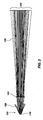
- the performance of the mixing rod 136 can be significantly enhanced with the addition of periodic features or "ripples" 150 on the outside walls of the mixing rod, as shown in FIGS. 1 and 3 . As illustrated in FIG.
- light from multiple LEDs of different colors 154 are introduced through one end of the mixing rod 136 and emanate from another end of the mixing rod 136 as a composite white light 158.
- One particular embodiment combines the light from four different colored LEDs (red, blue, green, and amber) to produce white light.
- the character of the white light can be changed. Specifically, white light with coordinated color temperatures (CCTs) of 4200°K and 5000°K can be produced while maintaining a high color rendering index (CRI), typically in excess of 75. Blue light typically occurs in the peak wavelength range of 445 nm to 465 nm.
- CCTs coordinated color temperatures
- CRI color rendering index
- Green light typically occurs in the dominant wavelength range of 520 nm to 550 nm, amber light in the range of 584 nm to 597 nm, and red light in the range of 613 nm to 645 nm.
- a rod support 138 can be used to secure mixing rod 136 in place.
- LEDs of each color can be mounted using reflow surface mount techniques to achieve optimum optical density.
- a conventional metal core board (MCB) 130 can be used.
- a conventional fiberglass laminate (FR4) printed circuit board (PCB) material can be used.
- LEDs, particularly red and amber LEDs, have the characteristic that their light output decreases significantly as their temperature raises. Heat management can be critical to maintaining optimum light output and therefore the proper ratios of light intensity to maintain the desired CCT and CRI.
- the lamp 100 of the present invention includes a number of different operating modes which provide different light characteristics, as described in Table 1.
- Table 1 Nominal Approximate relative peak intensity Mode CCT (°K) CRI Blue Green Amber Red Comments "Cool white” 5,000 70+ 0.72 0.70 0.75 1.00 Meets European user preference for cooler white light.
- "No-cure" N/A N/A ⁇ 0 0.30 0.60 1.00 Greatly reduced flux below 500 nm will not cure dental adhesives.
- the ratios of the four colors are controlled with a variation of pulsed width modulation of the current.
- each color is independently characterized for peak wavelength, spectral spread (full width half max), and illuminance (lux) at the image plane at a predetermined maximum current.
- spectral spread full width half max
- illuminance lux
- These tables then can be stored on an electronic memory device (chip) that matches the serial number of the lamp.
- the PWM controller looks up the duty cycle table on the memory chip and sets the duty cycles accordingly when the lamp is first started.
- the test software algorithm can also produce and store duty cycle tables for the full range of operating board temperatures, as discussed in more detail below.
- temperature compensation or measurement may be included. Since each color LED has a different sensitivity to heat, a compensation algorithm can be used to set the drive current values for each color as a function of temperature. The compensation algorithm may be adapted to assume that LEDs of a given color do not exhibit significant differences in temperature sensitivity. As a result, each lamp need not be characterized thermally but rather may depend on the theoretical and empirically determined temperature relationships in the algorithm. A thermistor on the LED circuit board may also be included to measure actual board temperature from which the LED temperature can be derived, based on previously determined empirical values, and the current to each LED color can be adjusted accordingly by software.
- a dental operatory lamp used to illuminate an operating area comprises a housing having a front directed toward the operating area and a rear away from the operating area, and a reflector module located at the rear of the housing.
- An electrical power supply is provided for supplying electrical power to the LEDs for illuminating the LEDs, with the power supply being selectively operable to provide an intensity adjustment for the LEDs.
- the electrical power supply can be selectively operable to control the level of power transmitted to each LED independent of the level of power transmitted to the other LEDs.
- the lamp can be configured to have a variable color output.
- the intensity adjustment can range from 0 to about 2500 FC.
- the intensity adjustment can be continuous throughout its range of adjustments or, alternatively, can be adjustable at discrete settings within its range of adjustments.
- the lamp may further include a microprocessor in communication with the LEDs to control the level of power transmitted to the LEDs, and thus the output intensity of the light from the lamp.
- Suitable microprocessors for use with the present invention are well known in the art and include, but are not limited to, any programmable digital electronic component that incorporates the functions of a central processing unit (CPU) on a single semiconducting integrated circuit (IC).
- a dental operatory lamp used to illuminate an operating area comprises a housing having a front directed toward the operating area and a rear facing away from the operating area.
- a plurality of light emitting diodes (LEDs) can be included.
- An adapter configured for receiving at least one non-light emitting diode (non-LED) light source is located within the housing.
- the at least one non-LED light source may consist of a group of lights that can be selected from, for example, Quartz halogen, tungsten halogen, incandescent, xenon, fluorescent, fiber optics, gas plasma, laser, ultraviolet, and blue light.
- the at least one non-LED light source may also include the group of lights selected from, for example, dental curing light, oral cancer screening light, decay detection (cavities and caries) blood detection sterilization and tooth whitening light.
- a particular embodiment of the invention includes a dental operatory lamp used to illuminate an operating area having a housing with a front directed toward the operating area and a rear away from the operating area.
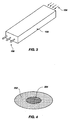
- the LEDs 118 are positioned with their longitudinal axes aligned toward predetermined points on the reflective element 116 for directing the light from the LEDs 118 toward the front of the lamp in a pattern that focuses light from the lamp to a central area of illumination of high intensity 204, with significantly reduced intensity illumination 202 outside the central area, as shown in FIG. 4 .
- Particular representative patterns of focused light emanating from the dental operatory lamps of the present invention include, for example, a pattern of focused light that can be elliptically shaped and may be about 3 inches by about 6 inches (7.62 cm by about 15.24 cm) in size.
- the reduced intensity illumination 202 outside the central area of illumination 204 decreases in intensity by 50% of a maximum intensity relative to the central area of illumination of high intensity.
- the central area of illumination of high intensity 204 can have a pattern size of at least 50 mm by 25 mm.
- the reduced intensity illumination 202 outside the central area can be configured to decrease in intensity progressively and smoothly relative to the central area of illumination of high intensity:
- the pattern can be configured to have a brightness of greater than about 20,000 Lux at a focus height of 700 mm from a target.
- the illumination on the central area of illumination of high intensity 204 at a distance of 60 mm can be configured to be less than about 1200 Lux.
- Illumination at the maximum level of the dental operating light in the spectral region of 180 nm to 400 nm can be configured to not exceed 0.008 W/m2.
- a dental operatory lamp used to illuminate an operating area includes a lamp assembly 208 having a front 210 directed toward the operating area and a rear 212 away from the operating area.
- a reflector module 220 can be located within the lamp assembly 208, and more specifically, can be located at the rear 212 of the lamp assembly 208.
- a plurality of light emitting diodes (LEDs) can optionally be located in a reflector module 222.
- a light mixing rod (not shown) may be included as part of the reflector module 222 to produce homogenous light from the multiple LEDs of different colors.
- the lamp assembly 208 can include a curved or faceted interior reflective surface 220.
- the LEDs can be directed toward the curved or faceted interior reflective surface 220 for directing the light from the LEDs toward the front 210 of the lamp in a pattern that focuses light from the lamp to a central area of illumination of high intensity, with significantly reduced intensity illumination outside the central area.
- the reduced intensity illumination outside the central area can be configured to decrease in intensity by 50% of a maximum intensity relative to the central area of illumination of high intensity.
- the reduced intensity illumination outside the central area may be configured to decrease in intensity progressively and smoothly relative to the central area of illumination of high intensity.
- the light pattern can have a brightness of greater than about 20,000 Lux at a focus height of 700 mm from a target.
- the illumination on the central area of illumination of high intensity at a distance of 60 mm may be less than about 1200 Lux.
- the illumination at the maximum level of the dental operating light in the spectral region of 180 nm to 400 nm may be configured to not exceed 0.008 W/m 2 .
- the lamp 100 of the present invention allows the user to set various chromaticity settings, such as sunlight equivalent D65 or simulated fluorescent lighting for improved dental shade matching. It also allows the addition of thermal, color, or intensity feedback to better maintain light characteristics over the life of the product, and permits adjustment of light intensity independent of color setting.
- the lamp 100 also is adapted to provide different configurations and forms of color mixing light guides. Specifically, the lamp 100 provides a user selectable mode with reduced irradiance in the near UV and blue wavelengths to allow adequate illumination while not initiating curing of UV-curable dental composites and adhesives.
- the lamp design can provide longer life through use of LEDs instead of incandescent bulbs and which can be further achieved through use of heat pipes, finned rear housing and fan cooling which maintain low LED temperature even at high currents.
Landscapes
- Engineering & Computer Science (AREA)
- General Engineering & Computer Science (AREA)
- Dental Tools And Instruments Or Auxiliary Dental Instruments (AREA)
- Non-Portable Lighting Devices Or Systems Thereof (AREA)
Description
- This invention relates to apparatus that produce visible light. It is particularly directed to an electrically powered light source including a light emitting diode (LED) having variable chromaticity, which is adapted for use in a dental operatory.
- It has been known for an extended period of time that electricity may be harnessed to create visible light. Incandescent light emitting elements powered by electricity have been used for substantially the same period of time. However, such incandescent lights suffer from an inefficient conversion of electricity to visible light. The inefficient conversion process causes production of a considerable amount of heat, and emission of a significant amount of radiation in, or near, the infrared spectrum. Such infrared emission inherently casts a heat load onto a target along with an illuminating beam. The heat generated by incandescent lighting may sometimes place an undesirable burden on environmental control systems, such as cooling systems used in dwellings. Both the inefficient conversion process, and removing the undesired heat load from the area near the light, lead to a correspondingly larger than necessary electric utility bill. Furthermore, in use on an operatory to illuminate an operating site on a patient, the infrared emissions may undesirably dry illuminated tissue, or may produce a feeling of discomfort in the patient.
- Alternative light emitting elements include fluorescent light bulbs. Such fluorescent bulbs advantageously produce a reduced heat load compared to incandescent bulbs. However, fluorescent bulbs tend to be bulky, and generally produce light of a less desirable color and intensity for many applications. Furthermore, certain electrical components required in the electric circuit powering the fluorescent bulbs, such as the ballast, tend to produce an undesirable amount of noise. In use in an operatory, it is generally desired to reduce the bulk of a lamp fixture, to reduce its intrusion into the operating arena, and to facilitate ease of manipulation of the lamp fixture.
- The majority of currently marketed dental exam lights use incandescent bulbs as light sources. These incandescent dental exam lights possess a number of disadvantages, such as: emission of infra-red (IR) radiation that must be removed with filters or so-called 'cold-mirrors' to prevent excessive warming of the patient and user; relatively short bulb life-time; inability of the user to adjust light color temperature and chromaticity of light; color temperature becoming lower and the light becoming "warmer" (i.e., shifting from white to orange/red), when light intensity is reduced (dimmed); and production of significant ultraviolet (UV) and blue light which causes undesired and uncontrolled curing of dental composites and adhesives.
- It would be an improvement to provide a more energy-efficient lamp fixture capable of producing a reduced heat load, and casting illumination having a desirable color and intensity that can be adjusted to obtain desirable spectra in a single lamp.
-
US 2006/0245173 A1 discloses a dental operatory lamp used to illuminate an operating area which may comprise a thermally conductive housing having a front directed toward the operating area and a rear away from the operating area, a reflector located on the rear of the thermally conductive housing, and a plurality of color LEDs projecting light toward the front of the housing. - A particular embodiment of the invention includes a dental operatory lamp used to illuminate an operating area which comprises a thermally conductive housing having a front directed toward the operating area and a rear away from the operating area; a generally elliptical reflector located on the rear of the thermally conductive housing; at least one heat pipe; a plurality of color LEDs projecting light toward the elliptical reflector, the plurality of LEDs being in thermal contact with the at least one heat pipe; and an optical light guide for combining light from said LEDs.
- The dental operatory lamp may provide at least two user selectable light spectral, one of said spectra providing white light with color temperature in the range 4000°K - 6000°K and one spectra having reduced output in the wavelength range 400-500 nm.
- The optical light guide may be configured to direct the light from the color LEDs toward the front of the lamp in a pattern that focuses white light from the lamp to a central area of illumination of high intensity, with significantly reduced intensity illumination outside the central area.
- While the specification concludes with claims particularly pointing out and distinctly claiming that which is regarded as the present invention, this invention can be more readily understood and appreciated by one of ordinary skill in the art from the following description of the invention when read in conjunction with the accompanying drawings in which:
-
FIG. 1 is a perspective view of a dental operatory lamp according to a particular embodiment of the invention; ; -
FIG. 2 illustrates a component arrangement and a representative LED light output in a dental operatory lamp; -
FIG. 3 illustrates an embodiment of an optical light guide in a dental operatory lamp of the invention; -
FIG. 4 illustrates a representative illumination pattern for the dental operatory lamp according to one embodiment of the invention; and -
FIG. 5 is a cross-section of a light module having a reflective interior reflective surface according to a particular embodiment of the invention. - Although the foregoing description contains many specifics, these should not be construed as limiting the scope of the present invention, but merely as providing illustrations of some representative embodiments. Similarly, other embodiments of the invention may be devised that do not depart from the scope of the present invention as defined in the claims. Features from different embodiments may be employed in combtnation.
-
FIG. 1 illustrates a perspective view of a current embodiment of the invention, generally indicated at 100, of a light source structure constructed according to principles of the invention.Light source structure 100 may generally be characterized as a lamp.Lamp 100 is powered by electricity, and functions to provide illumination to a work area disposed a distance from the lamp front, generally indicated at 102. Desirably, the work area illuminated bylamp 100 is shadow-free, and appears relatively uniform in illumination color and intensity. For most applications, the illuminated target work area is considered to have an approximately flat footprint and a depth normal to that footprint. That is, the illuminated region is generally structured to encompass a volume disposed proximate the footprint. - Illustrated
lamp 100 can include an attachment structure (not shown) operable to connectlamp 100 to suspension structure in the work area. Such an attachment structure is typically attached at aback 106 oflamp 100, although any convenient arrangement is operable. Typical suspension structure in a dental operatory permits a user to orient the lamp in space operably to aim the light output oflamp 100 at the desired target area. Certain embodiments of the invention provide a lamp having reduced weight and/or intrusive volume compared to commercially available lamps. Such reduced weight lamps permit a corresponding reduction in mass of the lamp suspension arrangement, thereby increasing ease of manipulation of the lamp to orient its output toward a target. - In use in an environment such as a dental operatory, a front shield (not shown) can be provided as a protective cover to block migration of dust and contaminated aerosols into the lamp interior. A front surface of such a shield may be structured to provide an easily cleanable surface, whereby to maintain sterility of the operatory area. In certain embodiments, the shield may incorporate one or more lenses to focus, or otherwise modify, the light output of
lamp 100. Whether or not a focusing lens is provided, a shield made from Lexan®, or other similar optically useful and formable material, can be provided to completely encase the front of a dental lamp to resist contamination of, and to facilitate cleaning of, the lamp. The shield may be injection molded and may include focusing lenses. Desirably, the shield, or a portion oflamp housing 114, can be hinged, or otherwise openable by a user, to provide access to the interior oflamp 100 for maintenance or replacement of a light generating element. - With reference to
FIG. 2 , anLED 118 emits light indicated by a plurality ofrays 120. An operable LED can include a 3 watt LED, such as that sold by Lumileds Lighting US, LLC under the Brand name Luxeon, part number LXHL-LW3C. - Typically, a reflective element, generally indicated at 116, is provided to direct the LED's light output toward a target. In a particular embodiment,
reflective element 116 can be a concave aspheric reflector which collects the light emanating from the mixing rod and focuses it onto the plane of the patient's face ("image plane"). The reflector surface contour can be a simple 2D ellipse section revolved around the central optical axis. A focusinglens 124 may be included in an arrangement effective to collimaterays 120 and further direct them to an illuminated area indicated at 126. In certain embodiments of the invention,area 126 corresponds to the target footprint of thelamp 100. In such case, it is desired that the illumination emitted from each module 108 is substantially uniform overarea 126.Certain rays 128 may be emitted in a direction other than desired for impingement onarea 126.Such rays 128 are characterized as stray light. As indicated by the illustrated collection ofrays 120,area 126 sometimes has a higher intensity of illumination at its center, and may fade to a decreased intensity near its perimeter, as discussed with reference toFIG. 4 . In another embodiment, theLED 118,mirror 122, and all associated optics are arranged in harmony to produce a substantially uniform intensity over its illuminated footprint at a selected focal distance. -
LEDs 118 are typically mounted onto a bracket 112 associated withlamp housing 114. Desirably, the bracket 112 assembly is structured to provide simple and rapid installation and removal ofLED 118, and includes connection structure for the electricity supplied to the LED and may further include a metalcore circuit board 130. It is further desirable for bracket 112 to be formed from a material capable of conducting heat or, alternatively, to be associated withheat conducting pipes 134. Advantageously, bracket 112 and/orheat pipe 134, together with housing 132 may be structured and arranged to dissipate any heat generated byLED 118 in a direction away from thefront 102 of thelamp 100. In some embodiments, use ofheat pipe 134 is particularly desirable since a large heat sink positioned directly behind the metal core board with the heat-generating LEDs may significantly obscure the light focusing onto the image plane. Through use of aheat pipe 134 or equivalent structure, the heat can be conducted away viaheat pipes 134 to a heat sink housing positioned on the back of the reflector where it does not obscure the light. An exemplary heat sink housing can includeheat sink fins 142. Theheat sink fins 142 can be integral with the outer housing of the lamp and constructed of any heat conducting or dissipating material, such as cast aluminum. To increase cooling, a fan can be used to draw air into agap 144 between the reflector and the heat sink housing. To maximize surface area and thus cooling, the inside of the heat sink/housing includes fins orribs 142 that form air channels therebetween. - In order to produce homogenous light from multiple LEDs of different colors (for example, red, greed, blue, and amber), the light emitting from each individual LED should sufficiently overlap the light from all the other LEDs. In a particular embodiment, a clear rectangular rod made of acrylic serves this function and is referred to herein as an optical light guide or a
light mixing rod 136. It is understood that the mixingrod 136 can be made out of any suitable material capable of acting as an optical light guide. The performance of the mixingrod 136 can be significantly enhanced with the addition of periodic features or "ripples" 150 on the outside walls of the mixing rod, as shown inFIGS. 1 and3 . As illustrated inFIG. 3 , light from multiple LEDs of different colors 154(e.g., red, green, blue, and/or amber) are introduced through one end of the mixingrod 136 and emanate from another end of the mixingrod 136 as a compositewhite light 158. One particular embodiment combines the light from four different colored LEDs (red, blue, green, and amber) to produce white light. By varying the ratios of the different colors, the character of the white light can be changed. Specifically, white light with coordinated color temperatures (CCTs) of 4200°K and 5000°K can be produced while maintaining a high color rendering index (CRI), typically in excess of 75. Blue light typically occurs in the peak wavelength range of 445 nm to 465 nm. Green light typically occurs in the dominant wavelength range of 520 nm to 550 nm, amber light in the range of 584 nm to 597 nm, and red light in the range of 613 nm to 645 nm. Arod support 138 can be used to secure mixingrod 136 in place. - Multiple LEDs of each color can be mounted using reflow surface mount techniques to achieve optimum optical density. In a particular embodiment, a conventional metal core board (MCB) 130 can be used. Alternatively, a conventional fiberglass laminate (FR4) printed circuit board (PCB) material can be used. LEDs, particularly red and amber LEDs, have the characteristic that their light output decreases significantly as their temperature raises. Heat management can be critical to maintaining optimum light output and therefore the proper ratios of light intensity to maintain the desired CCT and CRI.
- The
lamp 100 of the present invention includes a number of different operating modes which provide different light characteristics, as described in Table 1.Table 1 Nominal Approximate relative peak intensity Mode CCT (°K) CRI Blue Green Amber Red Comments "Cool white" 5,000 70+ 0.72 0.70 0.75 1.00 Meets European user preference for cooler white light. "Warm white" 4,200 70+ 1.00 0.80 0.75 1.00 Meets US user preference for warmer white light. "No-cure" N/A N/A ∼0 0.30 0.60 1.00 Greatly reduced flux below 500 nm will not cure dental adhesives. lamp 100, each color is independently characterized for peak wavelength, spectral spread (full width half max), and illuminance (lux) at the image plane at a predetermined maximum current. Using test software based on both theoretical and empirical predictions, these values are used to generate a table of duty cycles for each wavelength at each of the three operating conditions: 4200K, 5000K, and "No Cure" modes at start up (board temperature equal to ambient temperature). These tables then can be stored on an electronic memory device (chip) that matches the serial number of the lamp. The PWM controller then looks up the duty cycle table on the memory chip and sets the duty cycles accordingly when the lamp is first started. At this time, the test software algorithm can also produce and store duty cycle tables for the full range of operating board temperatures, as discussed in more detail below. - In a particular embodiment of the invention, temperature compensation or measurement may be included. Since each color LED has a different sensitivity to heat, a compensation algorithm can be used to set the drive current values for each color as a function of temperature. The compensation algorithm may be adapted to assume that LEDs of a given color do not exhibit significant differences in temperature sensitivity. As a result, each lamp need not be characterized thermally but rather may depend on the theoretical and empirically determined temperature relationships in the algorithm. A thermistor on the LED circuit board may also be included to measure actual board temperature from which the LED temperature can be derived, based on previously determined empirical values, and the current to each LED color can be adjusted accordingly by software.
- In another embodiment, a dental operatory lamp used to illuminate an operating area comprises a housing having a front directed toward the operating area and a rear away from the operating area, and a reflector module located at the rear of the housing. An electrical power supply is provided for supplying electrical power to the LEDs for illuminating the LEDs, with the power supply being selectively operable to provide an intensity adjustment for the LEDs. The electrical power supply can be selectively operable to control the level of power transmitted to each LED independent of the level of power transmitted to the other LEDs. The lamp can be configured to have a variable color output. For example, the intensity adjustment can range from 0 to about 2500 FC. The intensity adjustment can be continuous throughout its range of adjustments or, alternatively, can be adjustable at discrete settings within its range of adjustments. The lamp may further include a microprocessor in communication with the LEDs to control the level of power transmitted to the LEDs, and thus the output intensity of the light from the lamp. Suitable microprocessors for use with the present invention are well known in the art and include, but are not limited to, any programmable digital electronic component that incorporates the functions of a central processing unit (CPU) on a single semiconducting integrated circuit (IC).
- In an alternative embodiment of the invention, a dental operatory lamp used to illuminate an operating area comprises a housing having a front directed toward the operating area and a rear facing away from the operating area. A plurality of light emitting diodes (LEDs) can be included. An adapter configured for receiving at least one non-light emitting diode (non-LED) light source is located within the housing. The at least one non-LED light source may consist of a group of lights that can be selected from, for example, Quartz halogen, tungsten halogen, incandescent, xenon, fluorescent, fiber optics, gas plasma, laser, ultraviolet, and blue light. The at least one non-LED light source may also include the group of lights selected from, for example, dental curing light, oral cancer screening light, decay detection (cavities and caries) blood detection sterilization and tooth whitening light.
- A particular embodiment of the invention includes a dental operatory lamp used to illuminate an operating area having a housing with a front directed toward the operating area and a rear away from the operating area. The
LEDs 118 are positioned with their longitudinal axes aligned toward predetermined points on thereflective element 116 for directing the light from theLEDs 118 toward the front of the lamp in a pattern that focuses light from the lamp to a central area of illumination ofhigh intensity 204, with significantly reducedintensity illumination 202 outside the central area, as shown inFIG. 4 . Particular representative patterns of focused light emanating from the dental operatory lamps of the present invention include, for example, a pattern of focused light that can be elliptically shaped and may be about 3 inches by about 6 inches (7.62 cm by about 15.24 cm) in size. In a particular embodiment, the reducedintensity illumination 202 outside the central area ofillumination 204 decreases in intensity by 50% of a maximum intensity relative to the central area of illumination of high intensity. The central area of illumination ofhigh intensity 204 can have a pattern size of at least 50 mm by 25 mm. The reducedintensity illumination 202 outside the central area can be configured to decrease in intensity progressively and smoothly relative to the central area of illumination of high intensity: The pattern can be configured to have a brightness of greater than about 20,000 Lux at a focus height of 700 mm from a target. The illumination on the central area of illumination ofhigh intensity 204 at a distance of 60 mm can be configured to be less than about 1200 Lux. Illumination at the maximum level of the dental operating light in the spectral region of 180 nm to 400 nm can be configured to not exceed 0.008 W/m2. - Yet another embodiment of the invention is shown in
FIG. 5 , wherein a dental operatory lamp used to illuminate an operating area includes alamp assembly 208 having a front 210 directed toward the operating area and a rear 212 away from the operating area. Areflector module 220 can be located within thelamp assembly 208, and more specifically, can be located at the rear 212 of thelamp assembly 208. A plurality of light emitting diodes (LEDs) can optionally be located in areflector module 222. Optionally, a light mixing rod (not shown) may be included as part of thereflector module 222 to produce homogenous light from the multiple LEDs of different colors. Thelamp assembly 208 can include a curved or faceted interiorreflective surface 220. The LEDs can be directed toward the curved or faceted interiorreflective surface 220 for directing the light from the LEDs toward the front 210 of the lamp in a pattern that focuses light from the lamp to a central area of illumination of high intensity, with significantly reduced intensity illumination outside the central area. The reduced intensity illumination outside the central area can be configured to decrease in intensity by 50% of a maximum intensity relative to the central area of illumination of high intensity. The reduced intensity illumination outside the central area may be configured to decrease in intensity progressively and smoothly relative to the central area of illumination of high intensity. The light pattern can have a brightness of greater than about 20,000 Lux at a focus height of 700 mm from a target. The illumination on the central area of illumination of high intensity at a distance of 60 mm may be less than about 1200 Lux. The illumination at the maximum level of the dental operating light in the spectral region of 180 nm to 400 nm may be configured to not exceed 0.008 W/m2. - The
lamp 100 of the present invention allows the user to set various chromaticity settings, such as sunlight equivalent D65 or simulated fluorescent lighting for improved dental shade matching. It also allows the addition of thermal, color, or intensity feedback to better maintain light characteristics over the life of the product, and permits adjustment of light intensity independent of color setting. Thelamp 100 also is adapted to provide different configurations and forms of color mixing light guides. Specifically, thelamp 100 provides a user selectable mode with reduced irradiance in the near UV and blue wavelengths to allow adequate illumination while not initiating curing of UV-curable dental composites and adhesives. The lamp design can provide longer life through use of LEDs instead of incandescent bulbs and which can be further achieved through use of heat pipes, finned rear housing and fan cooling which maintain low LED temperature even at high currents. - Although the foregoing description contains many specifics, these are not to be construed as limiting the scope of the present invention, but merely as providing certain representative embodiments. Similarly, other embodiments of the invention can be devised which do not depart from the scope of the present invention. The scope of the invention is, therefore, indicated and limited only by the appended claims and their legal equivalents, rather than by the foregoing description. All additions, deletions, and modifications to the invention, as disclosed herein, which fall within the meaning and scope of the claims, are encompassed by the present invention.
Claims (18)
- A dental operatory lamp (100) used to illuminate an operating area comprising:a thermally conductive housing (114) having a front directed toward the operating area (102) and a rear away from the operating area (106);a reflector (116, 220) located on the rear of the thermally conductive housing; and a plurality of color LEDs (118,222); characterised in that the plurality of color LEDs (118, 222) projects light toward the reflector;the reflector is generally elliptical, and in that the dental operatory lamp also comprises:at least one heat pipe (134), wherein the plurality of LEDs is in thermal contact with the at least one heat pipe; andan optical light guide (136) for combining light from said LEDs.
- The dental operatory lamp of claim 1, wherein the plurality of color LEDs comprises LEDs that emit at least three colors.
- The dental operatory lamp of claim 1, wherein the plurality of color LEDs comprises LEDs that emit red, blue, green, and amber light wavelengths.
- The dental operatory lamp of claim 1, wherein the optical light guide produces at least three operating modes with different light characteristics.
- The dental operatory lamp of claim 4, wherein the at least three operating modes include a cool white mode, a warm white mode, and a no cure mode.
- The dental operatory lamp of claim 1 or 4, further comprising at least two user selectable light spectra, a first spectra providing white light with color temperature in the range 4000°K - 6000°K and a second spectra having reduced output in the wavelength range 400-500 nm.
- The dental operatory lamp of claim 6, wherein the user selectable light spectra comprises varying ratios of at least three colors emanating from the color LEDs.
- The dental operatory lamp of claim 6, wherein the user selectable light spectra comprises various ratios of red, blue, green, and amber light emanating from the color LEDs
- The dental operatory lamp of claim 1, wherein the thermally conductive housing comprises cooling air channels (144) formed between the reflector and the rear of the thermally conductive housing.
- The dental operatory lamp of claim 9, wherein the cooling air channels are formed by fins (142).
- The dental operatory lamp of claim 1, wherein the generally elliptical reflector is shaped to direct the light from the LEDs toward the front of the lamp in a pattern that focuses light from the lamp to a central area of illumination of high intensity (204), with significantly reduced intensity illumination (202) outside the central area.
- The dental operatory lamp of claim 1, wherein the optical light guide directs the light from the LEDs toward the front of the lamp in a pattern that focuses light from the lamp to a central area of illumination of high intensity, with significantly reduced intensity illumination outside the central area.
- The dental operatory lamp of claim 12, wherein the optical light guide produces at least three operating modes with different light characteristics.
- The dental operatory lamp of claim 1, further comprising an electrical power supply for supplying electrical power to the LEDs for illuminating the LEDs, with the power supply being selectively operable to provide an intensity adjustment for the LEDs.
- The dental operatory lamp of claim 1, further comprising an adapter configured for receiving at least one non-light emitting diode (non-LED) light source within the housing.
- The dental operatory lamp of claim 1, further comprising a fan located at the rear of the of the thermally conductive housing.
- The dental operatory lamp of claim 1, wherein the optical light guide comprises periodic features on an exterior surface thereof (150).
- The dental operatory lamp of claim 1, wherein the lamp produces white light with coordinated color temperatures of between 4200°K and 5000°K, and maintaining a color rendering index in excess of 75.
Priority Applications (1)
| Application Number | Priority Date | Filing Date | Title |
|---|---|---|---|
| EP13176201.5A EP2649930B1 (en) | 2007-10-05 | 2008-08-14 | LED-based dental exam lamp with variable chromaticity |
Applications Claiming Priority (2)
| Application Number | Priority Date | Filing Date | Title |
|---|---|---|---|
| US11/867,876 US20080025013A1 (en) | 2005-05-02 | 2007-10-05 | Led-powered dental operatory light |
| PCT/US2008/009768 WO2009045251A1 (en) | 2007-10-05 | 2008-08-14 | Led-based dental exam lamp with variable chromaticity |
Related Child Applications (2)
| Application Number | Title | Priority Date | Filing Date |
|---|---|---|---|
| EP13176201.5A Division EP2649930B1 (en) | 2007-10-05 | 2008-08-14 | LED-based dental exam lamp with variable chromaticity |
| EP13176201.5 Division-Into | 2013-07-11 |
Publications (3)
| Publication Number | Publication Date |
|---|---|
| EP2203105A1 EP2203105A1 (en) | 2010-07-07 |
| EP2203105A4 EP2203105A4 (en) | 2011-05-25 |
| EP2203105B1 true EP2203105B1 (en) | 2013-10-09 |
Family
ID=40527429
Family Applications (2)
| Application Number | Title | Priority Date | Filing Date |
|---|---|---|---|
| EP08835676.1A Active EP2203105B1 (en) | 2007-10-05 | 2008-08-14 | Led-based dental exam lamp with variable chromaticity |
| EP13176201.5A Active EP2649930B1 (en) | 2007-10-05 | 2008-08-14 | LED-based dental exam lamp with variable chromaticity |
Family Applications After (1)
| Application Number | Title | Priority Date | Filing Date |
|---|---|---|---|
| EP13176201.5A Active EP2649930B1 (en) | 2007-10-05 | 2008-08-14 | LED-based dental exam lamp with variable chromaticity |
Country Status (7)
| Country | Link |
|---|---|
| US (1) | US20080025013A1 (en) |
| EP (2) | EP2203105B1 (en) |
| AU (1) | AU2008307694B2 (en) |
| BR (1) | BRPI0816491A2 (en) |
| CA (1) | CA2701728C (en) |
| ES (2) | ES2430617T3 (en) |
| WO (1) | WO2009045251A1 (en) |
Families Citing this family (13)
| Publication number | Priority date | Publication date | Assignee | Title |
|---|---|---|---|---|
| US8016470B2 (en) | 2007-10-05 | 2011-09-13 | Dental Equipment, Llc | LED-based dental exam lamp with variable chromaticity |
| US8459852B2 (en) * | 2007-10-05 | 2013-06-11 | Dental Equipment, Llc | LED-based dental exam lamp |
| DE102008027252A1 (en) | 2008-06-06 | 2009-12-17 | Zett Optics Gmbh | Dental lamp for use in dental treatment chair, has three lamp units, where each lamp unit comprises light emitting diode, which has radiation direction, and reflector is provided for reflecting light from light emitting diode |
| US9642687B2 (en) | 2010-06-15 | 2017-05-09 | The Procter & Gamble Company | Methods for whitening teeth |
| US10491357B2 (en) * | 2010-07-12 | 2019-11-26 | Entropic Communications Llc | Method and apparatus for using dynamic subchannels in a communications network |
| US8777451B2 (en) * | 2010-10-20 | 2014-07-15 | Air Motion Systems, Inc. | Device for uniform, large area flood exposure with LEDs |
| US9500340B2 (en) | 2011-10-25 | 2016-11-22 | A-Dec, Inc. | Dental light using LEDs |
| USD663889S1 (en) | 2011-10-25 | 2012-07-17 | A-Dec, Inc. | Handle of a dental light |
| USD663886S1 (en) | 2011-10-25 | 2012-07-17 | A-Dec, Inc. | Body of a dental light |
| USD663887S1 (en) | 2011-10-25 | 2012-07-17 | A-Dec, Inc. | Front face of a dental light shield |
| US8525441B2 (en) * | 2011-12-06 | 2013-09-03 | LT Lighting (Taiwan) Corp. | Lamp powering technology |
| US9207484B2 (en) | 2012-09-26 | 2015-12-08 | Apple Inc. | Computer LED bar and thermal architecture features |
| DE102016005806A1 (en) | 2016-05-11 | 2017-11-16 | Carl Zeiss Meditec Ag | Systems and methods for illuminating an object field during a process of processing a photo-induced-curing plastic |
Family Cites Families (28)
| Publication number | Priority date | Publication date | Assignee | Title |
|---|---|---|---|---|
| US3290496A (en) * | 1962-10-17 | 1966-12-06 | Arthur I Appleton | Lamp fixtures |
| US4298911A (en) * | 1979-11-30 | 1981-11-03 | Pichel Industries, Inc. | Lighting device for creating public attraction |
| US4608622A (en) * | 1983-12-28 | 1986-08-26 | Dentsply Research & Development Corp. | Multi-function light source |
| GB9011665D0 (en) | 1990-03-21 | 1990-07-11 | Stephenson Group | Recycling of fibre products |
| US5406176A (en) * | 1994-01-12 | 1995-04-11 | Aurora Robotics Limited | Computer controlled stage lighting system |
| FR2720752B1 (en) | 1994-06-07 | 1996-10-31 | Rhone Poulenc Chimie | Crosslinkable or crosslinked silicone composition, non-stick and printable. |
| US5624569A (en) | 1996-01-23 | 1997-04-29 | Nalco Chemical Company | Clarification of deinking process water |
| EP0745648A3 (en) | 1995-06-01 | 1997-12-10 | Dow Corning Corporation | Stable dispersible silicone compositions |
| US6120164A (en) * | 1997-11-25 | 2000-09-19 | Luminaria Ltd. | Multiple lamp lighting fixture |
| US6200134B1 (en) * | 1998-01-20 | 2001-03-13 | Kerr Corporation | Apparatus and method for curing materials with radiation |
| US6439888B1 (en) * | 1999-05-03 | 2002-08-27 | Pls Liquidating Llc | Optical source and method |
| US6290368B1 (en) * | 1999-05-21 | 2001-09-18 | Robert A. Lehrer | Portable reading light device |
| US20050099824A1 (en) * | 2000-08-04 | 2005-05-12 | Color Kinetics, Inc. | Methods and systems for medical lighting |
| TW512214B (en) * | 2000-01-07 | 2002-12-01 | Koninkl Philips Electronics Nv | Luminaire |
| US7320593B2 (en) * | 2000-03-08 | 2008-01-22 | Tir Systems Ltd. | Light emitting diode light source for curing dental composites |
| US20030215766A1 (en) * | 2002-01-11 | 2003-11-20 | Ultradent Products, Inc. | Light emitting systems and kits that include a light emitting device and one or more removable lenses |
| GB0217197D0 (en) | 2002-07-24 | 2002-09-04 | Dow Corning | Method of deinking |
| MXPA05001029A (en) * | 2002-07-25 | 2005-09-12 | Jonathan S Dahm | Method and apparatus for using light emitting diodes for curing. |
| BR0316715A (en) * | 2002-11-19 | 2005-10-18 | Den Mat Corp | Dental guide with light |
| US6991356B2 (en) * | 2002-12-20 | 2006-01-31 | Efraim Tsimerman | LED curing light |
| KR100643516B1 (en) * | 2003-05-06 | 2006-11-10 | 가부시키가이샤 모리타 세이사쿠쇼 | Medical irradiation apparatus |
| US6955444B2 (en) * | 2003-11-12 | 2005-10-18 | Visiled, Inc. | Surgical headlight |
| CN1977127B (en) * | 2004-03-30 | 2010-08-04 | 照明管理解决方案公司 | Apparatus and method for improved illumination area filling |
| DE102006004995A1 (en) * | 2005-02-01 | 2006-10-19 | Schott Ag | Luminaire for dental or surgical use |
| US7210814B2 (en) * | 2005-04-29 | 2007-05-01 | Ultradent Products, Inc. | Dental curing light with specially arranged LEDs |
| US7425077B2 (en) * | 2005-05-02 | 2008-09-16 | Pelton & Crane | LED-powered dental operatory light |
| EP1741975B1 (en) * | 2005-07-05 | 2011-09-07 | Frowein EZH GmbH | Operating lamp |
| US20070031777A1 (en) * | 2005-08-03 | 2007-02-08 | Bwt Property, Inc. | Multifunctional Dental Apparatus |
-
2007
- 2007-10-05 US US11/867,876 patent/US20080025013A1/en not_active Abandoned
-
2008
- 2008-08-14 AU AU2008307694A patent/AU2008307694B2/en not_active Ceased
- 2008-08-14 EP EP08835676.1A patent/EP2203105B1/en active Active
- 2008-08-14 WO PCT/US2008/009768 patent/WO2009045251A1/en not_active Ceased
- 2008-08-14 EP EP13176201.5A patent/EP2649930B1/en active Active
- 2008-08-14 CA CA2701728A patent/CA2701728C/en active Active
- 2008-08-14 BR BRPI0816491-6A2A patent/BRPI0816491A2/en not_active IP Right Cessation
- 2008-08-14 ES ES08835676T patent/ES2430617T3/en active Active
- 2008-08-14 ES ES13176201.5T patent/ES2539472T3/en active Active
Also Published As
| Publication number | Publication date |
|---|---|
| CA2701728A1 (en) | 2009-04-09 |
| EP2649930A1 (en) | 2013-10-16 |
| EP2203105A1 (en) | 2010-07-07 |
| AU2008307694B2 (en) | 2013-03-21 |
| EP2649930B1 (en) | 2015-06-10 |
| AU2008307694A1 (en) | 2009-04-09 |
| ES2430617T3 (en) | 2013-11-21 |
| CA2701728C (en) | 2014-12-23 |
| BRPI0816491A2 (en) | 2015-03-10 |
| WO2009045251A1 (en) | 2009-04-09 |
| EP2203105A4 (en) | 2011-05-25 |
| ES2539472T3 (en) | 2015-07-01 |
| US20080025013A1 (en) | 2008-01-31 |
Similar Documents
| Publication | Publication Date | Title |
|---|---|---|
| US8016470B2 (en) | LED-based dental exam lamp with variable chromaticity | |
| EP2649930B1 (en) | LED-based dental exam lamp with variable chromaticity | |
| US10386055B2 (en) | LED-based dental exam lamp | |
| US9222628B2 (en) | Color temperature tunable LED-based lamp module | |
| US7450028B2 (en) | Led operation light | |
| US20110037390A1 (en) | Multi-chip package LED lighting device | |
| US10767847B2 (en) | Photographic lighting device | |
| WO2007147242A1 (en) | Led luminaire | |
| US7425077B2 (en) | LED-powered dental operatory light | |
| JP2003519896A (en) | Lighting equipment | |
| US20060002135A1 (en) | Dental lamp particularly for medical and dental surgeries | |
| WO2009045223A1 (en) | Led-powered dental operatory light | |
| AU2013200374B2 (en) | LED-Based Dental Exam Lamp with Variable Chromaticity | |
| JP3084178U (en) | Surgical light |
Legal Events
| Date | Code | Title | Description |
|---|---|---|---|
| PUAI | Public reference made under article 153(3) epc to a published international application that has entered the european phase |
Free format text: ORIGINAL CODE: 0009012 |
|
| 17P | Request for examination filed |
Effective date: 20100504 |
|
| AK | Designated contracting states |
Kind code of ref document: A1 Designated state(s): AT BE BG CH CY CZ DE DK EE ES FI FR GB GR HR HU IE IS IT LI LT LU LV MC MT NL NO PL PT RO SE SI SK TR |
|
| AX | Request for extension of the european patent |
Extension state: AL BA MK RS |
|
| A4 | Supplementary search report drawn up and despatched |
Effective date: 20110427 |
|
| TPAC | Observations filed by third parties |
Free format text: ORIGINAL CODE: EPIDOSNTIPA |
|
| REG | Reference to a national code |
Ref country code: DE Ref legal event code: R079 Ref document number: 602008028036 Country of ref document: DE Free format text: PREVIOUS MAIN CLASS: A61B0001060000 Ipc: F21V0013040000 |
|
| GRAP | Despatch of communication of intention to grant a patent |
Free format text: ORIGINAL CODE: EPIDOSNIGR1 |
|
| RIC1 | Information provided on ipc code assigned before grant |
Ipc: F21V 13/04 20060101AFI20130301BHEP |
|
| GRAS | Grant fee paid |
Free format text: ORIGINAL CODE: EPIDOSNIGR3 |
|
| GRAA | (expected) grant |
Free format text: ORIGINAL CODE: 0009210 |
|
| AK | Designated contracting states |
Kind code of ref document: B1 Designated state(s): AT BE BG CH CY CZ DE DK EE ES FI FR GB GR HR HU IE IS IT LI LT LU LV MC MT NL NO PL PT RO SE SI SK TR |
|
| AX | Request for extension of the european patent |
Extension state: AL BA MK RS |
|
| REG | Reference to a national code |
Ref country code: GB Ref legal event code: FG4D |
|
| REG | Reference to a national code |
Ref country code: AT Ref legal event code: REF Ref document number: 635726 Country of ref document: AT Kind code of ref document: T Effective date: 20131015 Ref country code: CH Ref legal event code: EP |
|
| REG | Reference to a national code |
Ref country code: IE Ref legal event code: FG4D |
|
| REG | Reference to a national code |
Ref country code: ES Ref legal event code: FG2A Ref document number: 2430617 Country of ref document: ES Kind code of ref document: T3 Effective date: 20131121 |
|
| REG | Reference to a national code |
Ref country code: DE Ref legal event code: R082 Ref document number: 602008028036 Country of ref document: DE Representative=s name: DTS MUENCHEN PATENT- UND RECHTSANWAELTE, DE Ref country code: DE Ref legal event code: R082 Ref document number: 602008028036 Country of ref document: DE Representative=s name: DTS PATENT- UND RECHTSANWAELTE SCHNEKENBUEHL U, DE |
|
| REG | Reference to a national code |
Ref country code: DE Ref legal event code: R096 Ref document number: 602008028036 Country of ref document: DE Effective date: 20131205 |
|
| REG | Reference to a national code |
Ref country code: AT Ref legal event code: MK05 Ref document number: 635726 Country of ref document: AT Kind code of ref document: T Effective date: 20131009 |
|
| REG | Reference to a national code |
Ref country code: NL Ref legal event code: VDEP Effective date: 20131009 |
|
| PG25 | Lapsed in a contracting state [announced via postgrant information from national office to epo] |
Ref country code: SI Free format text: LAPSE BECAUSE OF FAILURE TO SUBMIT A TRANSLATION OF THE DESCRIPTION OR TO PAY THE FEE WITHIN THE PRESCRIBED TIME-LIMIT Effective date: 20131009 |
|
| REG | Reference to a national code |
Ref country code: LT Ref legal event code: MG4D |
|
| PG25 | Lapsed in a contracting state [announced via postgrant information from national office to epo] |
Ref country code: IS Free format text: LAPSE BECAUSE OF FAILURE TO SUBMIT A TRANSLATION OF THE DESCRIPTION OR TO PAY THE FEE WITHIN THE PRESCRIBED TIME-LIMIT Effective date: 20140209 Ref country code: BE Free format text: LAPSE BECAUSE OF FAILURE TO SUBMIT A TRANSLATION OF THE DESCRIPTION OR TO PAY THE FEE WITHIN THE PRESCRIBED TIME-LIMIT Effective date: 20131009 Ref country code: SE Free format text: LAPSE BECAUSE OF FAILURE TO SUBMIT A TRANSLATION OF THE DESCRIPTION OR TO PAY THE FEE WITHIN THE PRESCRIBED TIME-LIMIT Effective date: 20131009 Ref country code: NL Free format text: LAPSE BECAUSE OF FAILURE TO SUBMIT A TRANSLATION OF THE DESCRIPTION OR TO PAY THE FEE WITHIN THE PRESCRIBED TIME-LIMIT Effective date: 20131009 Ref country code: NO Free format text: LAPSE BECAUSE OF FAILURE TO SUBMIT A TRANSLATION OF THE DESCRIPTION OR TO PAY THE FEE WITHIN THE PRESCRIBED TIME-LIMIT Effective date: 20140109 Ref country code: HR Free format text: LAPSE BECAUSE OF FAILURE TO SUBMIT A TRANSLATION OF THE DESCRIPTION OR TO PAY THE FEE WITHIN THE PRESCRIBED TIME-LIMIT Effective date: 20131009 Ref country code: LT Free format text: LAPSE BECAUSE OF FAILURE TO SUBMIT A TRANSLATION OF THE DESCRIPTION OR TO PAY THE FEE WITHIN THE PRESCRIBED TIME-LIMIT Effective date: 20131009 |
|
| PG25 | Lapsed in a contracting state [announced via postgrant information from national office to epo] |
Ref country code: LV Free format text: LAPSE BECAUSE OF FAILURE TO SUBMIT A TRANSLATION OF THE DESCRIPTION OR TO PAY THE FEE WITHIN THE PRESCRIBED TIME-LIMIT Effective date: 20131009 Ref country code: PL Free format text: LAPSE BECAUSE OF FAILURE TO SUBMIT A TRANSLATION OF THE DESCRIPTION OR TO PAY THE FEE WITHIN THE PRESCRIBED TIME-LIMIT Effective date: 20131009 Ref country code: AT Free format text: LAPSE BECAUSE OF FAILURE TO SUBMIT A TRANSLATION OF THE DESCRIPTION OR TO PAY THE FEE WITHIN THE PRESCRIBED TIME-LIMIT Effective date: 20131009 Ref country code: CY Free format text: LAPSE BECAUSE OF FAILURE TO SUBMIT A TRANSLATION OF THE DESCRIPTION OR TO PAY THE FEE WITHIN THE PRESCRIBED TIME-LIMIT Effective date: 20131009 |
|
| PG25 | Lapsed in a contracting state [announced via postgrant information from national office to epo] |
Ref country code: PT Free format text: LAPSE BECAUSE OF FAILURE TO SUBMIT A TRANSLATION OF THE DESCRIPTION OR TO PAY THE FEE WITHIN THE PRESCRIBED TIME-LIMIT Effective date: 20140210 |
|
| REG | Reference to a national code |
Ref country code: DE Ref legal event code: R097 Ref document number: 602008028036 Country of ref document: DE |
|
| PG25 | Lapsed in a contracting state [announced via postgrant information from national office to epo] |
Ref country code: EE Free format text: LAPSE BECAUSE OF FAILURE TO SUBMIT A TRANSLATION OF THE DESCRIPTION OR TO PAY THE FEE WITHIN THE PRESCRIBED TIME-LIMIT Effective date: 20131009 |
|
| PLBE | No opposition filed within time limit |
Free format text: ORIGINAL CODE: 0009261 |
|
| STAA | Information on the status of an ep patent application or granted ep patent |
Free format text: STATUS: NO OPPOSITION FILED WITHIN TIME LIMIT |
|
| PG25 | Lapsed in a contracting state [announced via postgrant information from national office to epo] |
Ref country code: CZ Free format text: LAPSE BECAUSE OF FAILURE TO SUBMIT A TRANSLATION OF THE DESCRIPTION OR TO PAY THE FEE WITHIN THE PRESCRIBED TIME-LIMIT Effective date: 20131009 Ref country code: SK Free format text: LAPSE BECAUSE OF FAILURE TO SUBMIT A TRANSLATION OF THE DESCRIPTION OR TO PAY THE FEE WITHIN THE PRESCRIBED TIME-LIMIT Effective date: 20131009 Ref country code: RO Free format text: LAPSE BECAUSE OF FAILURE TO SUBMIT A TRANSLATION OF THE DESCRIPTION OR TO PAY THE FEE WITHIN THE PRESCRIBED TIME-LIMIT Effective date: 20131009 |
|
| 26N | No opposition filed |
Effective date: 20140710 |
|
| PG25 | Lapsed in a contracting state [announced via postgrant information from national office to epo] |
Ref country code: DK Free format text: LAPSE BECAUSE OF FAILURE TO SUBMIT A TRANSLATION OF THE DESCRIPTION OR TO PAY THE FEE WITHIN THE PRESCRIBED TIME-LIMIT Effective date: 20131009 |
|
| REG | Reference to a national code |
Ref country code: DE Ref legal event code: R097 Ref document number: 602008028036 Country of ref document: DE Effective date: 20140710 |
|
| PGFP | Annual fee paid to national office [announced via postgrant information from national office to epo] |
Ref country code: DE Payment date: 20140827 Year of fee payment: 7 Ref country code: FI Payment date: 20140827 Year of fee payment: 7 |
|
| PGFP | Annual fee paid to national office [announced via postgrant information from national office to epo] |
Ref country code: GB Payment date: 20140827 Year of fee payment: 7 Ref country code: FR Payment date: 20140818 Year of fee payment: 7 Ref country code: ES Payment date: 20140826 Year of fee payment: 7 |
|
| PGFP | Annual fee paid to national office [announced via postgrant information from national office to epo] |
Ref country code: IT Payment date: 20140822 Year of fee payment: 7 |
|
| PG25 | Lapsed in a contracting state [announced via postgrant information from national office to epo] |
Ref country code: MC Free format text: LAPSE BECAUSE OF FAILURE TO SUBMIT A TRANSLATION OF THE DESCRIPTION OR TO PAY THE FEE WITHIN THE PRESCRIBED TIME-LIMIT Effective date: 20131009 Ref country code: LU Free format text: LAPSE BECAUSE OF FAILURE TO SUBMIT A TRANSLATION OF THE DESCRIPTION OR TO PAY THE FEE WITHIN THE PRESCRIBED TIME-LIMIT Effective date: 20140814 |
|
| REG | Reference to a national code |
Ref country code: CH Ref legal event code: PL |
|
| PG25 | Lapsed in a contracting state [announced via postgrant information from national office to epo] |
Ref country code: LI Free format text: LAPSE BECAUSE OF NON-PAYMENT OF DUE FEES Effective date: 20140831 Ref country code: CH Free format text: LAPSE BECAUSE OF NON-PAYMENT OF DUE FEES Effective date: 20140831 |
|
| REG | Reference to a national code |
Ref country code: IE Ref legal event code: MM4A |
|
| PG25 | Lapsed in a contracting state [announced via postgrant information from national office to epo] |
Ref country code: IE Free format text: LAPSE BECAUSE OF NON-PAYMENT OF DUE FEES Effective date: 20140814 |
|
| REG | Reference to a national code |
Ref country code: DE Ref legal event code: R119 Ref document number: 602008028036 Country of ref document: DE |
|
| GBPC | Gb: european patent ceased through non-payment of renewal fee |
Effective date: 20150814 |
|
| PG25 | Lapsed in a contracting state [announced via postgrant information from national office to epo] |
Ref country code: IT Free format text: LAPSE BECAUSE OF NON-PAYMENT OF DUE FEES Effective date: 20150814 |
|
| PG25 | Lapsed in a contracting state [announced via postgrant information from national office to epo] |
Ref country code: BG Free format text: LAPSE BECAUSE OF FAILURE TO SUBMIT A TRANSLATION OF THE DESCRIPTION OR TO PAY THE FEE WITHIN THE PRESCRIBED TIME-LIMIT Effective date: 20131009 Ref country code: FI Free format text: LAPSE BECAUSE OF NON-PAYMENT OF DUE FEES Effective date: 20150814 |
|
| REG | Reference to a national code |
Ref country code: FR Ref legal event code: ST Effective date: 20160429 |
|
| PG25 | Lapsed in a contracting state [announced via postgrant information from national office to epo] |
Ref country code: GR Free format text: LAPSE BECAUSE OF FAILURE TO SUBMIT A TRANSLATION OF THE DESCRIPTION OR TO PAY THE FEE WITHIN THE PRESCRIBED TIME-LIMIT Effective date: 20140110 Ref country code: MT Free format text: LAPSE BECAUSE OF FAILURE TO SUBMIT A TRANSLATION OF THE DESCRIPTION OR TO PAY THE FEE WITHIN THE PRESCRIBED TIME-LIMIT Effective date: 20131009 |
|
| PG25 | Lapsed in a contracting state [announced via postgrant information from national office to epo] |
Ref country code: DE Free format text: LAPSE BECAUSE OF NON-PAYMENT OF DUE FEES Effective date: 20160301 Ref country code: TR Free format text: LAPSE BECAUSE OF FAILURE TO SUBMIT A TRANSLATION OF THE DESCRIPTION OR TO PAY THE FEE WITHIN THE PRESCRIBED TIME-LIMIT Effective date: 20131009 Ref country code: GB Free format text: LAPSE BECAUSE OF NON-PAYMENT OF DUE FEES Effective date: 20150814 Ref country code: HU Free format text: LAPSE BECAUSE OF FAILURE TO SUBMIT A TRANSLATION OF THE DESCRIPTION OR TO PAY THE FEE WITHIN THE PRESCRIBED TIME-LIMIT; INVALID AB INITIO Effective date: 20080814 |
|
| PG25 | Lapsed in a contracting state [announced via postgrant information from national office to epo] |
Ref country code: FR Free format text: LAPSE BECAUSE OF NON-PAYMENT OF DUE FEES Effective date: 20150831 |
|
| REG | Reference to a national code |
Ref country code: ES Ref legal event code: FD2A Effective date: 20160926 |
|
| PG25 | Lapsed in a contracting state [announced via postgrant information from national office to epo] |
Ref country code: ES Free format text: LAPSE BECAUSE OF NON-PAYMENT OF DUE FEES Effective date: 20150815 |