EP2202999A1 - Diaphragm and speaker including same - Google Patents
Diaphragm and speaker including same Download PDFInfo
- Publication number
- EP2202999A1 EP2202999A1 EP08832421A EP08832421A EP2202999A1 EP 2202999 A1 EP2202999 A1 EP 2202999A1 EP 08832421 A EP08832421 A EP 08832421A EP 08832421 A EP08832421 A EP 08832421A EP 2202999 A1 EP2202999 A1 EP 2202999A1
- Authority
- EP
- European Patent Office
- Prior art keywords
- diaphragm
- axis direction
- length
- segment
- major axis
- Prior art date
- Legal status (The legal status is an assumption and is not a legal conclusion. Google has not performed a legal analysis and makes no representation as to the accuracy of the status listed.)
- Withdrawn
Links
Images


Classifications
-
- H—ELECTRICITY
- H04—ELECTRIC COMMUNICATION TECHNIQUE
- H04R—LOUDSPEAKERS, MICROPHONES, GRAMOPHONE PICK-UPS OR LIKE ACOUSTIC ELECTROMECHANICAL TRANSDUCERS; ELECTRIC HEARING AIDS; PUBLIC ADDRESS SYSTEMS
- H04R7/00—Diaphragms for electromechanical transducers; Cones
- H04R7/02—Diaphragms for electromechanical transducers; Cones characterised by the construction
- H04R7/12—Non-planar diaphragms or cones
Definitions
- the present invention relates to a non-circular diaphragm and a speaker including the same.
- an electronic device such as a mobile phone includes a speaker, which is an acoustic device.
- the speaker includes a diaphragm on which a coil is arranged and a magnet, which faces toward the diaphragm spaced by a predetermined interval and which generates a magnetic field near the coil.
- the diaphragm vibrates in a direction orthogonal to both the direction of the electric current and the direction of the magnetic field.
- a known speaker includes a non-circular diaphragm, which has a major axis and a minor axis that are different from each other, so that it may be mounted in the limited component mounting space (e.g., elongated space).
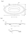
- the non-circular diaphragm, the major axis and the minor axis of which are different from each other, may include a diaphragm segment 104a having a partially-arched, oblong shape as shown in Fig. 5 or an elliptical shape as shown in Fig. 6 (for example, refer to patent publication 1).
- a diaphragm is molded from a thin film material having a predetermined strength such as engineering plastic (for example, refer to patent publication 2).
- residual stress generated when molding the diaphragm 104 from a thin film material may form an unnecessary depression H in the diaphragm segment 104a at an end region 104c in the major axis direction X as shown in Fig. 7 .
- the same kind of depression H may also be formed by the stress generated when the diaphragm 104 vibrates.
- the interval between the diaphragm 104 and a magnet (not shown), which faces toward the diaphragm 104 may become uneven. This may hinder proper vibration of the diaphragm 104.
- the invention recited in claim 1 is a diaphragm, which is non-circular and has a major axis and a minor axis that are different from each other, including a diaphragm segment.
- the diaphragm segment has a length in a major axis direction represented by 2a
- the diaphragm segment has a length in a minor axis direction represented by 2b
- a length from a center of the diaphragm to a boundary of the diaphragm segment in the major axis direction is represented by x
- a length from the center of the diaphragm to the boundary of the diaphragm segment in the minor axis direction is represented by y
- the diaphragm segment has a length in the major axis direction represented by 2a
- the diaphragm segment has a length in the minor axis direction represented by 2b
- the length from a center of the diaphragm to a boundary of the diaphragm segment in the major axis direction is represented by x
- the length from the center of the diaphragm to the boundary of the diaphragm segment in the minor axis direction is represented by y
- the shape of the boundary of the diaphragm segment satisfies equation 1.
- the curved shape of the boundary of the diaphragm segment at the end region of the diaphragm segment in the major axis direction is flatter than the prior art (i.e., the curvature is smaller). Accordingly, the residual stress generated when the diaphragm is molded and the stress generated when the diaphragm vibrates are less concentrated at the end region of the diaphragm segment in the major axis direction. This prevents the formation of unnecessary depressions in the end region of the diaphragm segment in the major axis direction. As a result, the speaker including the diaphragm reduces distortion components in the sound produced by the speaker.
- the invention recited in claim 2 is a speaker including the diaphragm according to claim 1.
- the prevent invention prevents the formation of unnecessary depressions at the end region of the diaphragm segment in the major axis direction and reduces distortion components in the sound produced by the speaker.
- the arrow Q in the drawings indicates the vibration direction of a diaphragm. Further, the arrow X indicates the major axis direction that is the longer direction of the diaphragm, and the arrow Y indicates the minor axis direction that is the shorter direction of the diaphragm.
- a speaker of the present invention includes an elongated box-shaped frame F.
- Two outer magnets 2, which extend in the major axis direction X and an inner magnet 3, which extends in the major axis direction X, are arranged in the frame F on a bottom plate 1, which is formed from a ferromagnetic.
- the outer magnets 2 each include an upper portion 21 and a lower portion 22, which are respectively an S pole and an N pole.
- the inner magnet 3 includes an upper portion 31 and a lower portion 32, which are respectively an N pole and an S pole. Accordingly, the inner magnet 3 is arranged between the outer magnets 2. This generates a magnetic flux loop with the outer magnets 2 and the inner magnet 3 in the directions of the arrows C in Fig. 2 .
- the frame F supports a diaphragm 4, which has a generally planar shape and is arranged above the outer magnets 2 and the inner magnet 3 spaced by a predetermined interval.
- the diaphragm 4 includes a rim 41, which is fixed to the frame F, and a vibratable diaphragm segment 4a.
- the rim 41 and the diaphragm segment 4a are formed integrally.
- the diaphragm segment 4a includes a peripheral portion 42, which defines a peripheral diaphragm, and a coil mounting portion 43 and dome portion 44, which define a central diaphragm segment.
- the peripheral portion 42 encompasses the central diaphragm segment (i.e., the coil mounting portion 43 and the dome portion 44).
- the rim 41 is formed to be planar so that it may be placed on a support surface 12, which is formed in an upper portion of the frame F to support the diaphragm 4.
- the peripheral portion 42 is formed to be convex in the vibration direction Q so as to support and allow vibration of the coil mounting portion 43 and the dome portion 44, which define the central diaphragm segment.
- the coil mounting portion 43 is formed to be planar so that a coil 5 may be mounted to its lower surface 43a.
- the dome portion 44 is formed to be convex in the vibration direction Q.
- a flattened coil 5 formed from a conductive wire that is wound about an axis parallel to the vibration direction Q is fixed to the lower surface 43a of the coil mounting portion 43. Since the direction of a magnetic field near the coil 5 is the minor axis direction Y, when electric current flows through the coil 5, the diaphragm 4 may be vibrated in a direction (i.e., vibration direction Q) perpendicular to the direction of the electric current (major axis direction X) and the direction of the magnetic field (minor axis direction Y).
- a cover 6 including sound holes 61 is arranged above the diaphragm 4.
- the cover 6 has an end portion 62, which holds the rim 41 of the diaphragm 4 in cooperation with the support surface 12 of the frame F.
- the feature of the present embodiment is in that the diaphragm segment 4a has a boundary 42a forming a cubic curve as shown in Fig. 3 .
- the feature of the present invention will now be described in detail.
- the major axis ⁇ , the minor axis ⁇ , and the lengths ⁇ , ⁇ , s, t, u, and v are shown using the same unit of length.
- the diaphragm 4 of the present embodiment is a non-circular diaphragm 4 having a major axis ⁇ (i.e., the length of the diaphragm 4 in the major axis direction X) and a minor axis ⁇ (i.e., the length of the diaphragm 4 in the minor axis direction Y).
- the ratio of the major axis ⁇ relative to the minor axis ⁇ (major axis ⁇ / minor axis ⁇ ) is, for example, 1.985.
- the ratio of the length ⁇ of the diaphragm segment 4a in the major axis direction X relative to the length ⁇ of the diaphragm segment 4a is 2.18.
- x represents the length s from the center O of the diaphragm 4 to the boundary 42a of the diaphragm segment 4a in the major axis direction X
- y represents the length t from the center O of the diaphragm 4 to the boundary 42a of the diaphragm segment 4a in the minor axis direction Y
- a represents a length that is half the length ⁇ of the diaphragm segment 4a in the major axis direction X
- b represents a length that is half the length ⁇ of the diaphragm segment 4a in the minor axis direction Y.
- the diaphragm 4 of the present embodiment prevents its center of gravity from moving away from the center O of the diaphragm 4 and thereby decreases distortion components in the sound produced by the speaker. That is, when the boundary of a diaphragm segment is partially arched, the position of the center of the arch moves the center of gravity. Thus, when molding the diaphragm, if part of the periphery of the diaphragm cannot be formed to have the appropriate arched shape, the center of gravity of the diaphragm is deviated from the center of the diaphragm.
- the diaphragm 4 vibrates inclined relative to the vibration direction. This easily increases distortion components in the sound produced by the speaker.
- the boundary 42a of the diaphragm segment 4a is shaped so that equation (1) is satisfied throughout the entire boundary 42a of the diaphragm segment 4a.
- the center of gravity of the diaphragm 4 is prevented from being deviated from the center O.
- the diaphragm 4 is vibrated parallel to the vibration direction Q, and distortion components in the sound produced by the speaker are decreased.
- a periphery 41a of the rim 41 is shaped to satisfy equation (2), which is shown below.
- Z 3 c 3 + W 3 d 3 1
- Equation (2) z represents the length u from the center O of the diaphragm 4 to the periphery 41 a of the rim 41 in the major axis direction X, and w represents the length v from the center O of the diaphragm 4 to the periphery 41a of the rim 41 in the minor axis direction Y.
- c represents a length that is half the length of the major axis ⁇ , and b represents a length that is half the length of the minor axis ⁇ .
- the diaphragm 4 of the above-described embodiment has the advantages described below.
- the speaker of the present embodiment includes the diaphragm 4.
- the speaker obviously has the above-described advantages (1) and (2).
- the rim 41 and the diaphragm segment 4a are formed integrally. However, they do not have to be formed integrally.
- the peripheral portion 42, which defines the peripheral diaphragm segment, and the coil mounting portion 43 and the dome portion 44, which define the central diaphragm segment may be formed to be either integral or not integral.
- the audio device including the diaphragm is a speaker.
- the audio device may be a telephone receiver.
Landscapes
- Engineering & Computer Science (AREA)
- Multimedia (AREA)
- Physics & Mathematics (AREA)
- Acoustics & Sound (AREA)
- Signal Processing (AREA)
- Diaphragms For Electromechanical Transducers (AREA)
- Audible-Bandwidth Dynamoelectric Transducers Other Than Pickups (AREA)
Abstract
Description
- The present invention relates to a non-circular diaphragm and a speaker including the same.
- Generally, an electronic device such as a mobile phone includes a speaker, which is an acoustic device. The speaker includes a diaphragm on which a coil is arranged and a magnet, which faces toward the diaphragm spaced by a predetermined interval and which generates a magnetic field near the coil. When electric current flows through the coil, the diaphragm vibrates in a direction orthogonal to both the direction of the electric current and the direction of the magnetic field.
- Further, since electronic devices such as mobile phones have become smaller in size, the space available for mounting components in an electronic device has decreased. A known speaker includes a non-circular diaphragm, which has a major axis and a minor axis that are different from each other, so that it may be mounted in the limited component mounting space (e.g., elongated space). The non-circular diaphragm, the major axis and the minor axis of which are different from each other, may include a
diaphragm segment 104a having a partially-arched, oblong shape as shown inFig. 5 or an elliptical shape as shown inFig. 6 (for example, refer to patent publication 1). - Generally, in compact electronic devices such as mobile phones, a diaphragm is molded from a thin film material having a predetermined strength such as engineering plastic (for example, refer to patent publication 2).
- Patent Publication 1: Japanese Laid-Open Patent Publication No.
2005-184588 - Patent Publication 2: Japanese Laid-Open Patent Publication No.
2004-312085 - However, in the
non-circular diaphragm 104, of which major axis α and minor axis β are different from each other, as the ratio of the major axis α relative to the minor axis β (major axis α / minor axis β) increases, formation of a depression H tends to occur in thediaphragm segment 104a at an end region in the major axis direction X. This may easily distort the sound produced by the speaker. - More specifically, for example, residual stress generated when molding the
diaphragm 104 from a thin film material may form an unnecessary depression H in thediaphragm segment 104a at anend region 104c in the major axis direction X as shown inFig. 7 . The same kind of depression H may also be formed by the stress generated when thediaphragm 104 vibrates. In a speaker including thediaphragm 104 having such a depression H, the interval between thediaphragm 104 and a magnet (not shown), which faces toward thediaphragm 104, may become uneven. This may hinder proper vibration of thediaphragm 104. As a result, there is a tendency of distortion components in the sound produced by the speaker easily increasing near the minimum resonance frequency at which the vibration amplitude of thediaphragm 104 increases. - Accordingly, it is an object of the present invention to provide a diaphragm and a speaker including the diaphragm that prevents an unnecessary depression from being formed in a diaphragm segment at an end region in the major axis direction to reduce the distortion components in the sound produced by the speaker.
- The invention recited in
claim 1 is a diaphragm, which is non-circular and has a major axis and a minor axis that are different from each other, including a diaphragm segment. When the diaphragm segment has a length in a major axis direction represented by 2a, the diaphragm segment has a length in a minor axis direction represented by 2b, a length from a center of the diaphragm to a boundary of the diaphragm segment in the major axis direction is represented by x, and a length from the center of the diaphragm to the boundary of the diaphragm segment in the minor axis direction is represented by y, the boundary of the diaphragm segment is shaped to satisfy the following equation 1:
- In this structure, when the diaphragm segment has a length in the major axis direction represented by 2a, the diaphragm segment has a length in the minor axis direction represented by 2b, the length from a center of the diaphragm to a boundary of the diaphragm segment in the major axis direction is represented by x, and the length from the center of the diaphragm to the boundary of the diaphragm segment in the minor axis direction is represented by y, the shape of the boundary of the diaphragm segment satisfies
equation 1. Thus, the curved shape of the boundary of the diaphragm segment at the end region of the diaphragm segment in the major axis direction is flatter than the prior art (i.e., the curvature is smaller). Accordingly, the residual stress generated when the diaphragm is molded and the stress generated when the diaphragm vibrates are less concentrated at the end region of the diaphragm segment in the major axis direction. This prevents the formation of unnecessary depressions in the end region of the diaphragm segment in the major axis direction. As a result, the speaker including the diaphragm reduces distortion components in the sound produced by the speaker. - The invention recited in
claim 2 is a speaker including the diaphragm according toclaim 1. - This structure obtains the same advantages as the invention recited in
claim 1. - The prevent invention prevents the formation of unnecessary depressions at the end region of the diaphragm segment in the major axis direction and reduces distortion components in the sound produced by the speaker.
- An embodiment of the present invention will now be discussed with reference to the drawings. The arrow Q in the drawings indicates the vibration direction of a diaphragm. Further, the arrow X indicates the major axis direction that is the longer direction of the diaphragm, and the arrow Y indicates the minor axis direction that is the shorter direction of the diaphragm.
- Referring to
Figs. 1 and 2 , a speaker of the present invention includes an elongated box-shaped frame F. Twoouter magnets 2, which extend in the major axis direction X and aninner magnet 3, which extends in the major axis direction X, are arranged in the frame F on abottom plate 1, which is formed from a ferromagnetic. Theouter magnets 2 each include anupper portion 21 and alower portion 22, which are respectively an S pole and an N pole. Theinner magnet 3 includes an upper portion 31 and alower portion 32, which are respectively an N pole and an S pole. Accordingly, theinner magnet 3 is arranged between theouter magnets 2. This generates a magnetic flux loop with theouter magnets 2 and theinner magnet 3 in the directions of the arrows C inFig. 2 . - The frame F supports a
diaphragm 4, which has a generally planar shape and is arranged above theouter magnets 2 and theinner magnet 3 spaced by a predetermined interval. As shown inFig. 3 , thediaphragm 4 includes arim 41, which is fixed to the frame F, and a vibratable diaphragm segment 4a. Therim 41 and the diaphragm segment 4a are formed integrally. The diaphragm segment 4a includes aperipheral portion 42, which defines a peripheral diaphragm, and acoil mounting portion 43 anddome portion 44, which define a central diaphragm segment. Theperipheral portion 42 encompasses the central diaphragm segment (i.e., thecoil mounting portion 43 and the dome portion 44). - The
rim 41 is formed to be planar so that it may be placed on asupport surface 12, which is formed in an upper portion of the frame F to support thediaphragm 4. Theperipheral portion 42 is formed to be convex in the vibration direction Q so as to support and allow vibration of thecoil mounting portion 43 and thedome portion 44, which define the central diaphragm segment. Thecoil mounting portion 43 is formed to be planar so that acoil 5 may be mounted to itslower surface 43a. Thedome portion 44 is formed to be convex in the vibration direction Q. - A
flattened coil 5 formed from a conductive wire that is wound about an axis parallel to the vibration direction Q is fixed to thelower surface 43a of thecoil mounting portion 43. Since the direction of a magnetic field near thecoil 5 is the minor axis direction Y, when electric current flows through thecoil 5, thediaphragm 4 may be vibrated in a direction (i.e., vibration direction Q) perpendicular to the direction of the electric current (major axis direction X) and the direction of the magnetic field (minor axis direction Y). - A
cover 6 includingsound holes 61 is arranged above thediaphragm 4. Thecover 6 has anend portion 62, which holds therim 41 of thediaphragm 4 in cooperation with thesupport surface 12 of the frame F. - The feature of the present embodiment is in that the diaphragm segment 4a has a
boundary 42a forming a cubic curve as shown inFig. 3 . The feature of the present invention will now be described in detail. The major axis α, the minor axis β, and the lengths γ, δ, s, t, u, and v are shown using the same unit of length. - The
diaphragm 4 of the present embodiment is anon-circular diaphragm 4 having a major axis α (i.e., the length of thediaphragm 4 in the major axis direction X) and a minor axis β (i.e., the length of thediaphragm 4 in the minor axis direction Y). The ratio of the major axis α relative to the minor axis β (major axis α / minor axis β) is, for example, 1.985. Further, the ratio of the length γ of the diaphragm segment 4a in the major axis direction X relative to the length δ of the diaphragm segment 4a is 2.18. - In the present embodiment, when the length γ of the diaphragm segment 4a in the major axis direction X is 2a and the length δ of the diaphragm segment 4a in the short axis direction Y is 2b, the
boundary 42a of the diaphragm segment 4a is shaped to satisfy equation (1), which is shown below.
- In equation (1), x represents the length s from the center O of the
diaphragm 4 to theboundary 42a of the diaphragm segment 4a in the major axis direction X, and y represents the length t from the center O of thediaphragm 4 to theboundary 42a of the diaphragm segment 4a in the minor axis direction Y. Further, in equation (1), a represents a length that is half the length γ of the diaphragm segment 4a in the major axis direction X, and b represents a length that is half the length δ of the diaphragm segment 4a in the minor axis direction Y. - In contrast with a diaphragm segment of which boundary is partially arched, the
diaphragm 4 of the present embodiment prevents its center of gravity from moving away from the center O of thediaphragm 4 and thereby decreases distortion components in the sound produced by the speaker. That is, when the boundary of a diaphragm segment is partially arched, the position of the center of the arch moves the center of gravity. Thus, when molding the diaphragm, if part of the periphery of the diaphragm cannot be formed to have the appropriate arched shape, the center of gravity of the diaphragm is deviated from the center of the diaphragm. In a speaker including such a diaphragm, the diaphragm vibrates inclined relative to the vibration direction. This easily increases distortion components in the sound produced by the speaker. In thediaphragm 4 of the present embodiment, as shown inFig. 3 , theboundary 42a of the diaphragm segment 4a is shaped so that equation (1) is satisfied throughout theentire boundary 42a of the diaphragm segment 4a. Thus, in contrast to when the boundary of the diaphragm segment is formed to be partially arched, the center of gravity of thediaphragm 4 is prevented from being deviated from the center O. As a result, in a speaker including thediaphragm 4, thediaphragm 4 is vibrated parallel to the vibration direction Q, and distortion components in the sound produced by the speaker are decreased. - Further, in the present embodiment, when the length of the
rim 41 in the major axis direction X (i.e., major axis α) is 2c, and the length of therim 41 in the minor axis direction Y (i.e., minor axis β) is 2d, aperiphery 41a of therim 41 is shaped to satisfy equation (2), which is shown below.
- In equation (2), z represents the length u from the center O of the
diaphragm 4 to theperiphery 41 a of therim 41 in the major axis direction X, and w represents the length v from the center O of thediaphragm 4 to theperiphery 41a of therim 41 in the minor axis direction Y. Further, in equation (2), c represents a length that is half the length of the major axis α, and b represents a length that is half the length of the minor axis β. - The
diaphragm 4 of the above-described embodiment has the advantages described below. - (1) The
diaphragm 4 includes the non-circular diaphragm segment 4a of which the major axis α differs from the minor axis β. As described above, when the length γ is 2a, the length δ is 2b, the length s is x, and the length t is y, theboundary 42a of the diaphragm segment 4a is shaped to satisfy equation (1). Thus, as shown inFig. 3 , the curved shape of theboundary 42a of the diaphragm segment 4a at theend region 4c of the diaphragm segment 4a in the major axis direction X is flatter than the prior art (i.e., the curvature is smaller). Accordingly, the residual stress generated when thediaphragm 4 is molded and the stress generated when thediaphragm 4 vibrates are less concentrated at theend region 4c of the diaphragm segment 4a in the major axis direction X. This prevents the formation of unnecessary depressions in theend region 4c of the diaphragm segment 4a in the major axis direction X. In this case, thediaphragm 4 has a cross-sectional shape (the shape of the B-B cross-section taken inFig. 3 ) that is in linear symmetry about an axis formed along a straight line, which is parallel to the vibration direction and extends through the center O of thediaphragm 4. As a result, the speaker including thediaphragm 4 reduces distortion components in the sound produced by the speaker. - (2) The
diaphragm 4 further includes therim 41. As described above, when the length of therim 41 in the major axis direction X (i.e., major axis α) is 2c, the length of therim 41 in the minor axis direction Y (i.e., minor axis β) is 2d, the length u is z, and the length v is w, theperiphery 41a of therim 41 is shaped to satisfy equation (2). Thus, the residual stress generated during molding of thediaphragm 4 is less concentrated at the end region of therim 41 in the major axis direction X, and the same effects as advantage (1) are obtained. - Further, the speaker of the present embodiment includes the
diaphragm 4. Thus, the speaker obviously has the above-described advantages (1) and (2). - In the above-described embodiment, the
rim 41 and the diaphragm segment 4a are formed integrally. However, they do not have to be formed integrally. In the same manner, theperipheral portion 42, which defines the peripheral diaphragm segment, and thecoil mounting portion 43 and thedome portion 44, which define the central diaphragm segment, may be formed to be either integral or not integral. - In the above-described embodiment, the audio device including the diaphragm is a speaker. However, the audio device may be a telephone receiver.
-
-
Fig. 1 is a perspective view showing a speaker according to one embodiment of the present invention; -
Fig. 2 is a cross-sectional view of the speaker according to the embodiment of the present invention; -
Fig. 3 is an upper view showing a diaphragm according to the embodiment of the present invention; -
Fig. 4(a) is a cross-sectional view andFig. 4(b) is a partially enlarged view showing the diaphragm according to the embodiment of the present invention; -
Fig. 5 is an upper view showing a diaphragm of the prior art; -
Fig. 6 is an upper view showing the diaphragm of the prior art; and -
Fig. 7(a) is a cross-sectional view andFig. 7(b) is a partially enlarged view showing the diaphragm of the prior art. - α ... major axis, β ... minor axis, γ, δ, s, t, u, v ... lengths, O ... center, X ... major axis direction, Y ... minor axis direction, F ... frame, 1 ... bottom plate, 2 ... outer magnets, 3 ... inner magnet, 4 ... diaphragm, 4a ... diaphragm segment, 4c ... end region, 5 ... coil, 6 ... cover, 42 ... peripheral portion (peripheral diaphragm segment), 42a ... boundary.
Claims (2)
- A diaphragm, which is non-circular and has a major axis and a minor axis that are different from each other, including a diaphragm segment, the diaphragm being characterized in that:when the diaphragm segment has a length in a major axis direction represented by 2a, the diaphragm segment has a length in a minor axis direction represented by 2b, a length from a center of the diaphragm to a boundary of the diaphragm segment in the major axis direction is represented by x, and a length from the center of the diaphragm to the boundary of the diaphragm segment in the minor axis direction is represented by y, the boundary of the diaphragm segment is shaped to satisfy the following equation 1:

- A speaker comprising the diaphragm according to claim 1.
Applications Claiming Priority (2)
| Application Number | Priority Date | Filing Date | Title |
|---|---|---|---|
| JP2007246073A JP5178108B2 (en) | 2007-09-21 | 2007-09-21 | Diaphragm and speaker equipped with the same |
| PCT/JP2008/066760 WO2009038084A1 (en) | 2007-09-21 | 2008-09-17 | Diaphragm and speaker including same |
Publications (1)
| Publication Number | Publication Date |
|---|---|
| EP2202999A1 true EP2202999A1 (en) | 2010-06-30 |
Family
ID=40467894
Family Applications (1)
| Application Number | Title | Priority Date | Filing Date |
|---|---|---|---|
| EP08832421A Withdrawn EP2202999A1 (en) | 2007-09-21 | 2008-09-17 | Diaphragm and speaker including same |
Country Status (6)
| Country | Link |
|---|---|
| US (1) | US20100284562A1 (en) |
| EP (1) | EP2202999A1 (en) |
| JP (1) | JP5178108B2 (en) |
| CN (1) | CN101855916A (en) |
| TW (1) | TW200922363A (en) |
| WO (1) | WO2009038084A1 (en) |
Family Cites Families (11)
| Publication number | Priority date | Publication date | Assignee | Title |
|---|---|---|---|---|
| JPS58169787U (en) * | 1982-05-08 | 1983-11-12 | ソニー株式会社 | speaker cabinet |
| JP3471447B2 (en) * | 1994-11-16 | 2003-12-02 | 日本碍子株式会社 | Ceramic diaphragm structure and method of manufacturing the same |
| UA51671C2 (en) * | 1995-09-02 | 2002-12-16 | Нью Транзд'Юсез Лімітед | Acoustic device |
| KR19990037723A (en) * | 1995-09-02 | 1999-05-25 | 헨리 에이지마 | Loudspeaker with panel acoustic radiation element |
| US6003766A (en) * | 1995-09-02 | 1999-12-21 | New Transducers Limited | Vending machine |
| JPH1094088A (en) * | 1996-09-19 | 1998-04-10 | Matsushita Electric Ind Co Ltd | Speaker |
| JP3874183B2 (en) * | 2002-05-21 | 2007-01-31 | フォスター電機株式会社 | Diaphragm for electroacoustic transducer |
| US7634102B2 (en) * | 2003-12-22 | 2009-12-15 | Panasonic Corporation | Speaker and device using the same |
| JP2005184588A (en) * | 2003-12-22 | 2005-07-07 | Matsushita Electric Ind Co Ltd | Speaker and electronic device using the same |
| JP2006287418A (en) * | 2005-03-31 | 2006-10-19 | Pioneer Electronic Corp | Speaker apparatus |
| EP2227036B8 (en) * | 2005-05-25 | 2013-09-11 | Knowles Electronics Asia PTE. Ltd. | Improved membrane for an electroacoustic transducer |
-
2007
- 2007-09-21 JP JP2007246073A patent/JP5178108B2/en not_active Expired - Fee Related
-
2008
- 2008-08-29 TW TW097133067A patent/TW200922363A/en unknown
- 2008-09-17 WO PCT/JP2008/066760 patent/WO2009038084A1/en not_active Ceased
- 2008-09-17 CN CN200880107817A patent/CN101855916A/en active Pending
- 2008-09-17 EP EP08832421A patent/EP2202999A1/en not_active Withdrawn
-
2009
- 2009-09-17 US US12/678,438 patent/US20100284562A1/en not_active Abandoned
Non-Patent Citations (1)
| Title |
|---|
| See references of WO2009038084A1 * |
Also Published As
| Publication number | Publication date |
|---|---|
| CN101855916A (en) | 2010-10-06 |
| TW200922363A (en) | 2009-05-16 |
| JP2009077300A (en) | 2009-04-09 |
| US20100284562A1 (en) | 2010-11-11 |
| JP5178108B2 (en) | 2013-04-10 |
| WO2009038084A1 (en) | 2009-03-26 |
Similar Documents
| Publication | Publication Date | Title |
|---|---|---|
| US10149063B2 (en) | Vibrating body for acoustic transducer and speaker device | |
| JP4886853B2 (en) | Speaker device | |
| JP4677341B2 (en) | Speaker device and mobile phone | |
| KR101079072B1 (en) | Multifunction oscillatory actuator | |
| US7961553B2 (en) | Sensory signal output apparatus | |
| JP2007174233A (en) | Speaker instrument and portable telephone | |
| EP2475190A1 (en) | Multifunctional micro-speaker | |
| CN109863756A (en) | Bone conduction speaker and bone conduction headphone device | |
| EP1768448A2 (en) | Moulded surround with integrated lead-out wires | |
| US10979815B2 (en) | Speaker | |
| JPH09275599A (en) | Electroacoustic transducer | |
| JP2008092560A (en) | Electroacoustic transducer | |
| CN101091414A (en) | Vibration plate and speaker unit using same | |
| US20100284562A1 (en) | Diaphragm and speaker including same | |
| CN103987005A (en) | Loudspeaker device | |
| KR100623509B1 (en) | Vibrating speaker | |
| JPH1118182A (en) | Mobile terminal device | |
| CN108702577A (en) | Loud speaker | |
| JPH052199U (en) | Electromagnetic electroacoustic device | |
| CN111921827A (en) | vibration generating device | |
| KR200333043Y1 (en) | Vibration speaker | |
| JPH0879890A (en) | Movable iron piece type speaker | |
| KR101140237B1 (en) | Multi function speaker using mesh cover | |
| US8565471B2 (en) | Speaker unit and portable information terminal | |
| KR101369331B1 (en) | Sound transducer |
Legal Events
| Date | Code | Title | Description |
|---|---|---|---|
| PUAI | Public reference made under article 153(3) epc to a published international application that has entered the european phase |
Free format text: ORIGINAL CODE: 0009012 |
|
| 17P | Request for examination filed |
Effective date: 20100415 |
|
| AK | Designated contracting states |
Kind code of ref document: A1 Designated state(s): AT BE BG CH CY CZ DE DK EE ES FI FR GB GR HR HU IE IS IT LI LT LU LV MC MT NL NO PL PT RO SE SI SK TR |
|
| AX | Request for extension of the european patent |
Extension state: AL BA MK RS |
|
| RIN1 | Information on inventor provided before grant (corrected) |
Inventor name: KODA, YOSHIKO Inventor name: KOSUDA, KAZUYUKI |
|
| DAX | Request for extension of the european patent (deleted) | ||
| STAA | Information on the status of an ep patent application or granted ep patent |
Free format text: STATUS: THE APPLICATION HAS BEEN WITHDRAWN |
|
| 18W | Application withdrawn |
Effective date: 20120815 |