EP2202992A2 - Image processing method and apparatus therefor - Google Patents
Image processing method and apparatus therefor Download PDFInfo
- Publication number
- EP2202992A2 EP2202992A2 EP09179198A EP09179198A EP2202992A2 EP 2202992 A2 EP2202992 A2 EP 2202992A2 EP 09179198 A EP09179198 A EP 09179198A EP 09179198 A EP09179198 A EP 09179198A EP 2202992 A2 EP2202992 A2 EP 2202992A2
- Authority
- EP
- European Patent Office
- Prior art keywords
- depth
- background
- information
- depth map
- shot
- Prior art date
- Legal status (The legal status is an assumption and is not a legal conclusion. Google has not performed a legal analysis and makes no representation as to the accuracy of the status listed.)
- Withdrawn
Links
Images


Classifications
-
- H—ELECTRICITY
- H04—ELECTRIC COMMUNICATION TECHNIQUE
- H04N—PICTORIAL COMMUNICATION, e.g. TELEVISION
- H04N21/00—Selective content distribution, e.g. interactive television or video on demand [VOD]
- H04N21/40—Client devices specifically adapted for the reception of or interaction with content, e.g. set-top-box [STB]; Operations thereof
- H04N21/43—Processing of content or additional data, e.g. demultiplexing additional data from a digital video stream; Elementary client operations, e.g. monitoring of home network or synchronising decoder's clock; Client middleware
- H04N21/434—Disassembling of a multiplex stream, e.g. demultiplexing audio and video streams, extraction of additional data from a video stream; Remultiplexing of multiplex streams; Extraction or processing of SI; Disassembling of packetised elementary stream
-
- H—ELECTRICITY
- H04—ELECTRIC COMMUNICATION TECHNIQUE
- H04N—PICTORIAL COMMUNICATION, e.g. TELEVISION
- H04N13/00—Stereoscopic video systems; Multi-view video systems; Details thereof
- H04N13/10—Processing, recording or transmission of stereoscopic or multi-view image signals
- H04N13/106—Processing image signals
- H04N13/172—Processing image signals image signals comprising non-image signal components, e.g. headers or format information
- H04N13/178—Metadata, e.g. disparity information
-
- H—ELECTRICITY
- H04—ELECTRIC COMMUNICATION TECHNIQUE
- H04N—PICTORIAL COMMUNICATION, e.g. TELEVISION
- H04N13/00—Stereoscopic video systems; Multi-view video systems; Details thereof
-
- H—ELECTRICITY
- H04—ELECTRIC COMMUNICATION TECHNIQUE
- H04N—PICTORIAL COMMUNICATION, e.g. TELEVISION
- H04N13/00—Stereoscopic video systems; Multi-view video systems; Details thereof
- H04N13/10—Processing, recording or transmission of stereoscopic or multi-view image signals
- H04N13/106—Processing image signals
- H04N13/128—Adjusting depth or disparity
-
- H—ELECTRICITY
- H04—ELECTRIC COMMUNICATION TECHNIQUE
- H04N—PICTORIAL COMMUNICATION, e.g. TELEVISION
- H04N13/00—Stereoscopic video systems; Multi-view video systems; Details thereof
- H04N13/10—Processing, recording or transmission of stereoscopic or multi-view image signals
- H04N13/106—Processing image signals
- H04N13/161—Encoding, multiplexing or demultiplexing different image signal components
-
- H—ELECTRICITY
- H04—ELECTRIC COMMUNICATION TECHNIQUE
- H04N—PICTORIAL COMMUNICATION, e.g. TELEVISION
- H04N2213/00—Details of stereoscopic systems
- H04N2213/003—Aspects relating to the "2D+depth" image format
Definitions
- aspects of the present invention relate to an image processing method and apparatus therefor, and more particularly, to an image processing method and apparatus therefor which generate a depth map about a frame by using depth information extracted from metadata.
- Three-dimensional image technology aims to realize a realistic image by applying depth information to a two-dimensional image.
- Three-dimensional image technology is generally classified into an image generating technique for generating video data as a three-dimensional image from the start, and an image converting technique for converting video data, which is generated as a two-dimensional image, into a three-dimensional image.
- image generating technique for generating video data as a three-dimensional image from the start
- image converting technique for converting video data, which is generated as a two-dimensional image, into a three-dimensional image.
- research is being conducted to study both of these two techniques.
- aspects of the present invention provide an image processing method and apparatus therefor which generate a depth map about an object based on background depth information.
- an image processing method includes extracting shot information from metadata, wherein the shot information classifies a series of two-dimensional images into predetermined units; determining whether frames classified as a predetermined shot can be reproduced as a three-dimensional image based on shot type information included in the shot information; extracting background depth information from the metadata if the frames classified as the predetermined shot can be reproduced as a three-dimensional image, wherein the background depth information relates to a background of the frames classified as the predetermined shot; generating a depth map about the background of the frames based on the background depth information; if the frames classified as the predetermined shot comprise an object, extracting object depth information about the object from the metadata; and generating a depth map about the object based on the object depth information.
- the image processing method may further include calculating a time at which the frames classified as the predetermined shot are required to be output based on the shot information.
- the generating of the depth map about the background may include extracting information from the background depth information, the information including background type information indicating a basic composition of the background, surface information for applying a depth value to a surface included in the background, coordinate points of the background, a depth value at each of the coordinate points of the background, and a panel position value indicating a depth value of a screen.
- the generating of the depth map about the background may include generating the depth map about the background based on a depth value of the basic composition of the background according to the background type information, and a depth value of the surface according to the surface information.
- the image processing method may further include filtering the depth map about the background if the background of the frames have the same depth values, and the filtering of the depth map about the background includes applying a hemisphere-shaped filter, a hemicylinder-shaped filter, or a triangular prism-shaped filter to the depth map about the background so as to modify the depth map of the background.
- the object depth information may include object type information identifying a type of the object as a two-dimensional object, a normal object, or a highlight object.
- the object depth information may include priority order information indicating a depth map generation order for the plurality of objects
- the generating of the depth map about the object may include sequentially generating depth maps about the plurality of objects according to the depth map generation order.
- the generating of the depth map about the object may include obtaining a time at which the frames including the object are required to be output based on the object depth information.
- the image processing method may further include extracting area identification information identifying an area of the object from the object depth information, wherein the area identification information corresponds to information in which the area of the object is denoted as a coordinate point, or corresponds to a mask in which a shape of the object is marked.
- the generating of the depth map about the object may include the generating a depth map about the two-dimensional object based on the panel position value included in the background depth information that is determined based on a depth value of the area of the object.
- the object depth information may further include information about one or more background coordinate points from among coordinate points of the background included in the background depth information and which are equal to one or more coordinate points indicating an area of the normal object, and generating of the depth map about the object may include the operation of generating a depth map about the normal object based on depth values of the one or more background coordinate points that are determined based on depth values of the area of the normal object.
- the generating of the depth map about the object may include obtaining one or more background coordinate points from among coordinate points of the background included in the background depth information and which are equal to coordinate points indicating an area of the normal object; and generating the depth map about the normal object based on depth values of the background coordinate points that are determined based on depth values of the area of the normal object.
- the operation of generating the depth map about the object may include the calculating a depth value of an area of the highlight object based on the panel position value included in the background depth information and an offset value included in the object depth information, and generating a depth map about the highlight object based on the a depth value of the area of the highlight object.
- the image processing method may further include filtering the depth map about the object, and the operation of filtering may include applying a hemisphere-shaped filter, a hemicylinder-shaped filter, or a triangular prism-shaped filter to the depth map about the object so as to modify the depth map about the object.
- the image processing method may further include extracting title identification information from the metadata, wherein the title identification information identifies a title including the frames, and thus determines which title is related to the metadata.
- the image processing method may further include generating a left-eye image and a right-eye image with respect to the two-dimensional image based on the depth map about the background and the depth map about the object; compensating for holes of the left-eye image and the right-eye image; and generating a three-dimensional format image based on the left-eye image and the right-eye image of which holes are compensated for.
- an image processing apparatus includes a metadata analyzing unit to extract shot information from metadata, based on shot type information included in the shot information, the shot information classifying a series of two-dimensional images into predetermined units, to extract background depth information from the metadata when frames classified as a predetermined shot can be reproduced as a three-dimensional image, the background depth information relating to a background of the frames classified as the predetermined shot, and to extract and analyze object depth information about the object from the metadata when the frames classified as the predetermined shot comprise an; and a depth map generating unit to generate a depth map about the background of the frames based on the background depth information, and to generatw a depth map about the object based the object depth information.
- a recording medium storing a computer readable program to execute an image processing method, the image processing method including extracting shot information from metadata, wherein the shot information classifies a series of two-dimensional images into predetermined units; determining whether frames classified as a predetermined shot can be reproduced as a three-dimensional image based on shot type information included in the shot information; extracting background depth information from the metadata if the frames classifies as the predetermined shot can be reproduced as a three-dimensional image, wherein the background depth information relates to a background of the frames classified as the predetermined shot; generating a depth map about the background of the frames based on the background depth information; if the frames classified as the predetermined shot comprise an object, extracting object depth information about the object from the metadata; and generating a depth map about the object based on the object depth information.
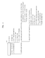
- FIG. 1 is a diagram of metadata 100 about video data, according to an embodiment of the present invention.
- the metadata 100 includes information about the video data.
- the metadata 100 includes title identification information identifying a title including the video data.
- the metadata 100 includes information about the frames comprising the video data.
- the information about the frames includes information classifying the frames according to a predetermined reference.
- a group of similar frames may be referred to as a 'unit', and the frames of the video data may be classified into a plurality of such units.
- the metadata 100 includes information classifying the frames of the video data into the plurality of units.
- a series of frames having such similar composition is referred to as a 'shot'.
- the metadata 100 includes information about a shot so as to classify frames of two-dimensional video data into predetermined units, that is, shot units.
- the information about the shot included in the metadata 100 is referred to as 'shot information'.
- the metadata 100 includes shot information for one or more shots. Where the composition of frames changes significantly, such that the composition of a current frame is different from the composition of a previous frame, the current frame and the previous frame are classified into different shots.
- the shot information includes shot type information, which is related to each of the shots, and indicates whether frames corresponding to the shot need to be output as a two-dimensional image or a three-dimensional image.
- shot type information about a shot indicates that frames included in the shot should be output as a two-dimensional image
- an image processing apparatus decodes the frames corresponding to the shot, and outputs the two-dimensional image on a screen of the image processing apparatus.
- shot type information about a shot indicates that frames included in the shot should be output as a three-dimensional image
- the image processing apparatus outputs the frames corresponding to the shot as the three-dimensional image based on depth information included in the metadata 100.
- the shot information includes information for synchronizing two-dimensional video data with depth information in order to output the two-dimensional video data as a three-dimensional image.
- the shot information includes a shot start time and a shot end time.
- the shot start time indicates an output time at which a first frame of the shot is output
- the shot end time indicates an output time at which the last frame of the shot is output.
- video data or a title which is a group of video data
- a sequential time axis in which the video data or the title is reproduced is referred to as a 'global time axis'.
- a presentation time of the video data or the title in the global time axis can be used as the shot start time and shot end time.
- the shot information includes information indicating the number of frames included in the shot. Since the shot information includes the shot start time and the shot end time and also includes the information about the number of frames included in the shot, the image processing apparatus outputs the frames included in the shot at regular intervals during a time period calculated by subtracting the shot start time from the shot end time. Thus, an output time of each of the frames included in the shot is calculated.
- the metadata 100 may further include depth information for converting the frames classified by the predetermined shot into the three-dimensional image.
- 'parallax' a distance between two points in the image formed on the eyes.
- Positive parallax indicates that the image appears to be within the screen itself.
- a parallax value of the positive parallax may be equal to or less than a distance between the eyes. As the parallax value increases, the three-dimensional effect is generated so that the image appears to be positioned deeper in the screen.
- the parallax value is 0.
- the image is formed at the plane of the screen so that the viewer does not experience a three-dimensional effect.
- Negative parallax indicates that the image is formed in front of the screen when the visual axes of the two eyes are crossed in front of the screen, and creates a three-dimensional effect so that the image appears to be protruding from the screen.
- aspects of the present invention may employ a method of giving depth to a frame by generating a depth map about the frame.
- Depth information indicates information for converting the two-dimensional image into the three-dimensional image by giving depth to the frame, and includes background depth information and object depth information.
- An image of a background and an image of one or more objects other the background together comprise an image of a frame.
- the background depth information gives depth to the image of the background.
- Giving depth to the image of the background refers to giving depth to the composition so as to allow the background to have a three-dimensional effect, wherein the composition includes a position of the background, a structure of a shape of the background, and the like.
- a background of a frame may have various forms for each frame.
- the various forms are classified into several types and included in the metadata 100.
- the metadata 100 also includes background type information for indicating which type of composition from among the classified compositions is related to a background of frames included in a predetermined shot.
- the shot is used to distinguish frames in the case where the composition of a current frame is different from the composition of a previous frame because the composition is changed between frames.
- Frames classified by shot generally have a similar composition.
- depth information about a background of the frames classified by the shot is also similar.
- the background depth information may further include surface information for giving a depth value to a surface included in the background.
- the background type information and the surface information will be described with reference to FIG. 3F .
- the background depth information may include coordinate points of the background, a depth value applied to each of the coordinate points of the background, and a panel position value. Values of the coordinate points indicate coordinate values of the background with respect to a two-dimensional image frame. The depth value indicates a degree of depth to be given to a predetermined pixel of the two-dimensional image, and a panel position indicates a position in the screen at which an image is formed.
- the background depth information may be employed to generate a depth map about a background of the frames included in the shot.
- an object other a background indicates a person, a building, and the like, which have a vertical component.
- the object depth information may be used to generate a depth map about the object.
- the background depth information may be necessary, but some of the frames in the shot may not include the object, thus, not every frame may need to be output, since the three-dimensional image may require the object depth information.
- the object depth information includes object type information.
- the object type information is classified into a two-dimensional object, a normal object, and a highlight object, according to how the depth value is applied to the object.
- a two-dimensional object identifies an area to be two-dimensionally output.
- a depth value of the two-dimensional object is equal to a depth value of the screen, that is, the panel position value.
- a normal object is an object in contact with the background. Thus, the normal object has a depth value equal to a depth value of a coordinate point of the background and which contacts the normal object.
- Objects that are neither two-dimensional objects nor normal objects are referred to as highlight objects.
- Highlight objects have a depth value equal to a value of a point inwardly or outwardly positioned in the screen by a predetermined value with respect to a depth value of the panel position.
- the object depth information includes priority order information.
- the priority order information indicates a depth map generation order for the plurality of objects.
- a depth map is first generated with respect to an object having the highest priority of the plurality of objects.
- An object having a high priority is an object that is positioned closer to a viewer than other objects with lower priority.
- the object depth information may also include information on a time at which a frame is output.
- the time at which the frame is output indicates a frame output time at which a predetermined object is shown from among frames of the shot.
- the frame output time includes a frame start time and a frame end time which respectively indicate a time at which an output of the frame including the predetermined object begins and a time at which an output of the frame including the predetermined object ceases.
- the object depth information includes area identification information.
- the area identification information identifies an area of an object and may be coordinate points.
- the area identification information may be a mask in which the area of the object is marked. In this case, a single mask is used for a single object so as to identify an area of the single object.
- the object depth information may further include reference information.
- the reference information relates to a coordinate point equal to a coordinate point of the background included in the background depth information that indicates an area of the normal object.
- the normal object indicates an object contacting the background, so that the normal object has an object depth value equal to a background depth value at the coordinate point contacting the background.
- the mask is used as the area identification information, it may not be possible to know which part of the object contacts the background, so that the reference information is necessary to indicate the part of the object that contacts the background.
- the object depth information may need to include information about the offset value as well.
- the object depth information may further include filter information. Since the object has a vertical component, depth values of all pixels of the object may be vertically even with each other. For example, since the depth value of the highlight object corresponds to the sum of, or the difference between, the panel position value and the offset value, all pixels of the highlight object may have the same depth value. In this case, the filter information may be necessary to add an additional depth value to the depth value of the object so as to make the object three-dimensional.
- the image processing apparatus may filter the object based on the filter information.
- the background depth information may include the filter information. Where an entire background has the same depth value, a depth map about the background may be filtered based on the filter information so that a three-dimensional effect may be given to the background.
- the filter information will be described in detail with reference to FIG. 5 .
- the metadata 100 includes information for converting the video data of the two-dimensional image into the three-dimensional image, and includes the background depth information and the object depth information.
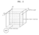
- FIG. 2 illustrates the depth information of FIG. 1 .
- the depth information may be used to give depth to a frame of a two-dimensional plane.
- an X-axis direction parallel to a direction, in which a viewer watches a screen indicates a degree of a depth of an image of the frame.
- the depth value may have a value between 0 through 255. As the depth value decreases and thus approaches 0, the image has a large depth so that the image is farther from the viewer. As the depth value increases and thus approaches 255, the image is closer to the viewer.
- a panel position indicates a position in a screen at which the image is formed
- a panel position value indicates a depth value of the image when parallax is 0, that is, when the image is formed at a plane of the screen.
- the panel position value may have a depth value between 0 through 255. If the panel position value is 255, the image included in the frame has a depth value equal to or smaller than a depth value of the screen so that the image is formed far away from the viewer, that is, an inner part of the screen, so that the image included in the frame has the zero-parallax or the positive parallax.
- the image included in the frame has a depth value equal to or larger than a depth value of the screen so that the image appears to be coming off the screen, that is, an outer part of the screen, so that the image included in the frame has a zero-parallax or a negative parallax.
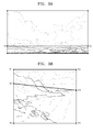
- FIGS. 3A through 3F illustrate a method of giving a depth value to a background based on the background type information and the surface information included in the background depth information.
- the background type information indicates basic composition of the background included in a frame.
- a background type may be broadly divided into six types. Table 1 below lists the six background types and FIGS. 3A through 3E correspond to basic compositions of the background according to the background type.
- Table 1 0x00 Reserved 0x01 Plain 0x02 Basic baseline 0x03 2 point baseline 0x04 5 point box 0x05 6 point box 0x06 8 point box 0x07 ⁇ 0xFF Reserved
- the plain composition may be further included as a background type.
- the plain composition corresponds to a case where the entire background has the same depth value.
- a background of a frame in FIG. 3A illustrates a case where the background type is a basic baseline.
- the composition of the basic baseline is used when a depth change occurs vertically in upper and lower areas with respect to a single line, such as a horizontal line parallel to a top line or a bottom line in the background.
- a coordinate value of an uppermost left point of the frame in FIG. 3A is (0,0)
- coordinate points p1 and p2 have coordinate values which are different in the X-axis but equal in the Y-axis.
- pixels of a straight line connecting the coordinate points p1 and p2 have equal depth values.
- depth information includes the coordinate points p1 and p2, a depth value to be applied to the straight line connecting the coordinate points p1 and p2, and depth values of the top line and the bottom line.
- a background of a frame in FIG. 3B illustrates a case of where the background type is a two-point baseline.
- the composition of the two-point baseline is used when a depth change occurs vertically and horizontally in upper and lower areas with respect to a single line not in parallel with a top line and a bottom line in the background.
- Coordinate values of coordinate points p3 and p4 in FIG. 3B are different in both X-axis and Y-axis directions, and depth values of the coordinate points p3 and p4 are also different. Pixels of a straight line connecting the coordinate points p3 and p4 have respectively different depth values.
- depth information includes coordinate points p3 and p4, the depth values to be applied to the coordinate points p3 and p4, and depth values of corner points p1, p2, p5, and p6.
- a background of a frame in FIG. 3C illustrates a case where the background type is a five-point box.
- the composition of the five-point box is used when the same depth area formed as a plane rectangle exists in the background and when a depth change occurs toward four outer points with respect to the plane rectangle.
- a coordinate point p3, and horizontal and vertical lengths X and Y are given to indicate the rectangle area.
- depth information includes coordinate points p1 through p5, depth values of the coordinate points p1 through p5, and the vertical and horizontal lengths of the plane rectangle.
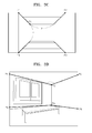
- a background of a frame in FIG. 3D illustrates a case where the background type is a six-point box.
- the composition of the six-point box is used when two specific points which have vertically different depth values are defined in the background and when a depth change occurs toward four outer points with respect to the two specific points.
- depth information includes coordinate points p1 through p6, and depth values of the coordinate points p1 through p6.
- a background of a frame in FIG. 3E illustrates a case where the background type is an eight-point box.
- the composition of the eight-point box is used when an area formed as a plane quadrangle exists in the background, wherein the plane quadrangle has four corner points each of which has different depth values, and when a depth change occurs toward four outer points with respect to the four corner points.
- depth information includes coordinate points p1 through p8 and depth values of the coordinate points p1 through p8.
- FIG. 3F illustrates a case where a depth value is additionally added to the basic composition of a background according to surface information.
- FIG. 3F illustrates a coordinate value for additionally adding a depth value to the background having background composition of a two-point baseline.
- the surface information includes a value of the coordinate value and a depth value of the coordinate value for additionally adding the depth value to the background.
- Depth information includes surface information including coordinate points p1 through p10, and depth values of the coordinate points p1 through p10.
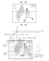
- FIG. 4 illustrates the depth given to an image when the image is viewed at a side of a screen.
- the image of the screen illustrated in FIG. 4 includes a two-dimensional object, a normal object, and a highlight object. Filtering is not performed on the objects of FIG. 4 , and pixels of each of the objects have the same depth values with respect to a Z-axis direction, that is, a direction in parallel with a panel position.
- the two-dimensional object When viewed at the side of the screen, the two-dimensional object is positioned on the screen so that the two-dimensional object has a depth value equal to the screen. Since the normal object stands while contacting a background, as illustrated in FIG. 4 , a depth value of the normal object is equal to a depth value at a background point at which the background and the normal object contact each other.
- the highlight object of FIG. 4 has a depth value corresponding to a sum of a panel position value and an offset value. Since the highlight object has a depth value larger than the panel position value in FIG. 4 , a viewer visually senses the highlight object of FIG. 4 as though the highlight object were coming off the screen.
- FIG. 5 illustrates a three-dimensional effect of an image filtered when an image processing apparatus filters a depth map about an object or a depth map about a background.
- the depth map about the object may be filtered.
- the depth map about the background may be filtered.
- FIG. 5 illustrates depths viewed from a side when the object or the background is filtered provided that the object or the background has the same depth value.
- the filtering operation is not limited to the case of FIG. 5 and thus may be performed although the object or the background does not have the same depth value.
- FIGS. 5A and 5B illustrate depths of a depth map filtered by a hemisphere-shaped filter.
- FIGS. 5A and 5B correspond to a case where the hemisphere-shaped filter is applied to the depth map in such a manner that a shape of the depth map about the object or a shape of the depth map about the background is a plane that passes through a center of a sphere.
- the object is the highlight object such as a soccer ball
- a depth map about the soccer ball may be filtered with a hemisphere-shaped filter.
- the human face may be regarded as a separate object but, for convenience of description, when it is assumed that the entire frame including the human face is a background, the hemisphere-shaped filter may be applied to a depth map about the human face so as to give a three-dimensional effect to the human face.
- FIGS. 5C and 5D illustrate depths of a depth map filtered by a hemicylinder-shaped filter.
- FIGS. 5C and 5D correspond to a case where the hemicylinder-shaped filter is applied to the depth map in such a manner that a shape of the depth map about the object or a shape of the depth map about the background may be a plane that vertically divides a cylinder in half.
- the hemicylinder-shaped filter may be used to give a three-dimensional effect to the telephone pole.
- FIGS. 5E and 5F correspond to a case where a triangular prism-shaped filter is applied to a depth map.
- the triangular prism-shaped filter may be applied to the depth map in such a manner that a rectangle-shaped side surface of the triangular prism can be in parallel with the depth map. By doing so, the depth map may be modified.
- FIG. 6 illustrates a method of generating a depth map by using the metadata 100 of FIG. 1 .
- FIG. 6A illustrates a two-dimensional image
- FIG. 6B corresponds to a case of where a depth value is given to a screen illustrated in FIG. 6A .
- the image processing apparatus (not shown) divides a frame into a background and an object, and generates background depth information and object depth information.
- a frame of the two-dimensional image includes a background of land and the sky, and an object including two trees, a person, and a balloon.
- the image processing apparatus extracts the background depth information from the metadata 100.
- the frame of FIG. 6A has a composition in which the horizon, that is, a horizontal line, has the largest depth.
- the image processing apparatus uses the background type information extracted from the metadata 100, and thus recognizes that the frame of FIG. 6A has the background composition of the basic baseline as illustrated in FIG. 3A .
- the image processing apparatus gives a depth value to the background based on information about a composition type, a coordinate point value of the background, and depth value information about the background, and thus generates a depth map about the background as illustrated in FIG. 6B .
- a depth value of a panel position is 255. Since the depth value of the panel position is the largest value, an image of the frame gives a three-dimensional effect by which the image appears to be within a screen.
- the horizontal line at which the sky contacts the land has a depth value of 0 so that the horizontal line is positioned farthest from a viewer.
- a bottom line of the land has a depth value of 255, meaning that an image of the bottom line is formed at a position closest to the viewer.
- the image processing apparatus extracts coordinate point information from area identification information so as to identify an area of an object, and identifies the object from the frame based on the coordinate point information.
- the area identification information may be a mask in which a shape of the object is marked, and in this case, the area of the object may be identified based on the mask.
- the image processing apparatus determines an object type for each of objects based on object type information included in the object depth information.
- the object includes the two trees, the human, a logo titled NBC, and a balloon. Since the two trees and the human contact the land, the two trees and the human are normal objects. Since the logo titled NBC is intended to be displayed on a two-dimensional screen, the logo is a two-dimensional object. Since the balloon is an object floating in the air, the balloon is a highlight object.
- the image processing apparatus identifies an area of each of the objects by using the area identification information.
- the image processing apparatus With respect to the two-dimensional object, the image processing apparatus generates a depth map about the two-dimensional object as illustrated in FIG. 6B based on the panel position value, which is included in the background depth information.
- the panel position value may be determined based on a depth value of the two-dimensional object.
- the image processing apparatus determines one or more points at which the normal object contacts the background, and extracts background depth values corresponding to coordinate point values of the points at which the normal object contacts the background.
- the image processing apparatus With respect to the highlight object, the image processing apparatus generates a depth map about the highlight object based on a depth value that is in turn calculated based on the panel position value and the offset value.
- the image processing apparatus may filter the depth maps. For example, the image processing apparatus may give a three-dimensional effect to the balloon in FIG. 6B by applying the hemisphere-shaped filter to the balloon.
- the depth maps about the objects may be generated by giving the depth values to the objects based on various methods according to the types of the objects.
- FIG. 7 is a block diagram of an image processing apparatus 700 to perform an image processing method according to an embodiment of the present invention.
- the image processing apparatus 700 includes a video data decoding unit 710, a metadata analyzing unit 720, a mask buffer 730, a depth map generating unit 740, and a stereo rendering unit 750.
- the image processing apparatus 700 may further include an output unit 760 that outputs a three-dimensional image, which is formed in a three-dimensional format, on a screen.
- the image forming apparatus may include additional and/or different units. Similarly, the functionality of two or more of the above units may be integrated into a single component.
- the video data decoding unit 710 reads video data from a disc (not shown) or a local storage (not shown), and decodes the video data.
- the metadata analyzing unit 720 reads metadata about video data 100 from the disc or the local storage, and analyzes the metadata about video data 100.
- the video data and/or the metadata about video data 100 may be stored in a server (not shown) or recorded to the disc in a multiplexed or independent manner.
- the image processing apparatus 700 may download the video data from the server and read the metadata about video data 100 from the disc, or may read the video data from the disc and download the metadata about video data 100 from the server.
- the image processing apparatus 700 may download and use the video data and/or the metadata about video data 100 from the server via a communication network.
- the server may be operated by a content provider, such as a broadcasting station or a general content manufacturing company, and stores the video data and/or the metadata about video data 100.
- the server extracts content requested by a user, and provides the content to the user.
- the image processing apparatus 700 may further include a communicating unit (not shown) and a local storage (not shown).
- the communicating unit requests the video data and/or the metadata about video data 100 from the server via a wired or wireless communication network, and receives the video data and/or the metadata about video data 100 (hereinafter, referred to as 'the metadata 100') from the server.
- the local storage stores information downloaded from the server.
- the local storage according to the present embodiment stores the video data and/or the metadata 100 transmitted from the server via the communicating unit.
- the video data decoding unit 710 and the metadata analyzing unit 720 respectively read the video data and the metadata 100 from the disc.
- the metadata 100 may be recorded in a lead-in area, a user data area, and/or a lead-out area of the disc.
- the metadata analyzing unit 720 extracts a disc identifier identifying the disc having the video data, and a title identifier indicating a title including the video data in the disc from the metadata 100, and determines which video data is related to the metadata 100 based on the disc identifier and the title identifier.
- the metadata analyzing unit 720 extracts an output time of a frame including an object from the metadata 100, and when an output time of a current frame is included in the output time of the frame including the object, the metadata analyzing unit 720 parses background depth information and object depth information about the current frame and transmits the background depth information and the object depth information to the depth map generating unit 740.
- the mask buffer 730 temporarily stores the mask to be applied to the frame.
- the mask may have different colors for a shape of the object and for a residual area of the frame except for the shape of the object. In other cases, a series of holes along an area of the object may be included in the mask. One mask may be necessary for one object.
- the depth map generating unit 740 generates a depth map about the frame based on the background depth information and the object depth information received from the metadata analyzing unit 720, and the mask received from the mask buffer 730.
- the depth map generating unit 740 generates a depth map about the background and a depth map about the object based on the metadata 100, combines the depth map about the background with the depth map about the object, and thus generates the depth map about the frame.
- the depth map generating unit 740 identifies an area of the object based on the area identification information included in the object depth information.
- the area identification information may be a value of a coordinate point indicating the area of the object, or may be the mask in which a shape of the object is marked.
- the depth map generating unit 740 recognizes the shape of the object based on information about the coordinate point or the mask, and gives a depth value to the recognized object.
- the depth map generating unit 740 extracts coordinate points from coordinate points in the area of the object and which is of a part contacting the background, and generates the depth map about the object based on depth values corresponding to the extracted coordinate points. If the object is a two-dimensional object, the depth map generating unit 740 generates a depth map about the two-dimensional object based on a panel position value. If the object is a highlight object, the depth map generating unit 740 generates a depth map about the highlight object based on an offset value and the panel position value.
- the depth map generating unit 740 generates the depth map about the frame based on the depth map about the background and the depth map about the object.
- the depth map generating unit 740 transmits the generated depth map about the frame to the stereo rendering unit 750.
- the stereo rendering unit 750 generates a left-eye image and a right-eye image based on a video image received from the video data decoding unit 710 and the depth map received from the depth map generating unit 740, and generates a three-dimensional format image including the left-eye image and the right-eye image.
- an output device may be included in the image processing apparatus 700.
- the output device is included in the image processing apparatus 700 as the output unit 760.
- the output unit 760 sequentially outputs the left-eye image and the right-eye image on the screen.
- the output unit 760 should output the images at a minimum frame rate of 120Hz.
- the output unit 760 sequentially displays the left-eye image and the right-eye image, which are included in the frame, by a unit of 1/120 sec.
- FIG. 8 is a detailed block diagram of the depth map generating unit 740 in the image processing apparatus 700 of FIG. 7 .
- the depth map generating unit 740 includes a background depth map generating unit 810, an object depth map generating unit 820, a filtering unit 830, and a depth map buffer unit 840.
- the background depth map generating unit 810 receives the background depth information from the metadata analyzing unit 720.
- the background depth information includes background type information, coordinate points of a background, depth values corresponding to the coordinate points of the background, and a panel position value, and generates the depth map about the background based on the background depth information.
- the background depth map generating unit 810 transmits the depth map about the background to the filtering unit 830.
- the object depth map generating unit 820 receives object depth information including area identification information and object type information from the metadata analyzing unit 720, and generates the depth map about the object based on the object depth information. If the area identification information relates to a mask, the object depth map generating unit 820 receives the mask to be applied to a corresponding frame from the mask buffer 730, and generates the depth map about the object based on the mask.
- the object depth map generating unit 820 requests the background depth map generating unit 810 for a background depth value corresponding to a coordinate point of a position at which the object contacts the background.
- the object depth map generating unit 820 receives the background depth value corresponding to a coordinate point of the position at which the object contacts the background from the background depth map generating unit 810, and generates the depth map about the object based on the background depth value as a depth value of the object.
- the object depth map generating unit 820 requests the background depth map generating unit 810 for a panel position value, and generates the depth map about the two-dimensional object based on the panel position value. If the object is a highlight object, the object depth map generating unit 820 generates the depth map about the highlight object based on the panel position value received from the background depth map generating unit 810 and an offset value included in the object depth information. If a plurality of objects are included in a frame, the object depth map generating unit 820 sequentially generates depth maps about the plurality of objects according to priority order information.
- the filtering unit 830 filters the depth map about the background and the depth map about the object. If pixels of the object have the same depth values, the filtering unit 830 may apply a filter to the depth map about the object so as to give a three-dimensional effect to the pixels of the object. If a shape of the depth map about the background is a plane, that is, if the entire background has the same depth value, the filter may be used to give a three-dimensional effect to the background.
- the depth map buffer unit 840 temporarily stores the depth map about the background filtered by the filtering unit 830, and when the depth map about the object is generated, updates a depth map about a frame by adding the depth map about the object to the depth map about the background. If the object includes a plurality of objects, the depth map buffer unit 840 sequentially overlays the depth maps about the plurality of objects, and thus, updates the depth map about the frame. When the depth map about the frame is completed, the depth map buffer unit 840 transmits the depth map about the frame to the stereo rendering unit 750.
- FIG. 9 is a detailed block diagram of the stereo rendering unit 750 in the image processing apparatus 700 of FIG. 7 .
- the stereo rendering unit 750 includes a stereo image generating unit 910, a hole compensating unit 920, a left-eye image buffer 930, a right-eye image buffer 940, and a three-dimensional format image generating unit 950.
- the stereo image generating unit 910 generates the left-eye image and the right-eye image based on the video image received from the video data decoding unit 710 and the depth map about the frame received from the depth map generating unit 740.
- the stereo image generating unit 910 calculates how far each pixel of a two-dimensional image should move in left and right directions based on the depth map about the frame, and generates the left-eye image and the right-eye image in which each of the pixels moves according to the calculation and is mapped to new positions.
- the hole compensating unit 920 compensates for holes generated in the left-eye image and the right-eye image.
- the pixels of the two-dimensional image are repeatedly mapped to some positions in the left-eye image and the right-eye image while the pixels of the two-dimensional image are not mapped to some other positions which are thus empty; these empty positions are referred to as holes.
- the hole compensating unit 920 compensates for these holes in the left-eye image and the right-eye image, and then transmits the left-eye image to the left-eye image buffer 930 and the right-eye image to the right-eye image buffer 940.
- the left-eye image buffer 930 and the right-eye image buffer 940 store the corresponding left-eye image and the right-eye image.
- the left-eye image buffer 930 and the right-eye image buffer 940 transmit the left-eye image and the right-eye image to the three-dimensional format image generating unit 950.
- the three-dimensional format image generating unit 950 generates the three-dimensional format image in such a manner that all of the left-eye image and the right-eye image may be included in the three-dimensional format image.
- the type of the three-dimensional format may be a top and down format, a side-by-side format, an interlaced format, etc.
- the three-dimensional format image generating unit 950 transmits the three-dimensional format image to the output device (not shown).
Abstract
Description
- This application claims the benefit of Korean Application No.
10-2008-0134951 - Aspects of the present invention relate to an image processing method and apparatus therefor, and more particularly, to an image processing method and apparatus therefor which generate a depth map about a frame by using depth information extracted from metadata.
- Due to the development of digital technologies, three-dimensional image technology has become widespread. Three-dimensional image technology aims to realize a realistic image by applying depth information to a two-dimensional image.
- Since human eyes are separated in a horizontal direction by a predetermined distance, two-dimensional images respectively viewed by the left eye and the right eye are different from each other so that binocular disparity occurs. The human brain combines the different two-dimensional images, and thus generates a three-dimensional image that looks realistic.
- Three-dimensional image technology is generally classified into an image generating technique for generating video data as a three-dimensional image from the start, and an image converting technique for converting video data, which is generated as a two-dimensional image, into a three-dimensional image. In this regard, research is being conducted to study both of these two techniques.
- Aspects of the present invention provide an image processing method and apparatus therefor which generate a depth map about an object based on background depth information.
- According to an aspect of the present invention, an image processing method is provided. The method includes extracting shot information from metadata, wherein the shot information classifies a series of two-dimensional images into predetermined units; determining whether frames classified as a predetermined shot can be reproduced as a three-dimensional image based on shot type information included in the shot information; extracting background depth information from the metadata if the frames classified as the predetermined shot can be reproduced as a three-dimensional image, wherein the background depth information relates to a background of the frames classified as the predetermined shot; generating a depth map about the background of the frames based on the background depth information; if the frames classified as the predetermined shot comprise an object, extracting object depth information about the object from the metadata; and generating a depth map about the object based on the object depth information.
- According to another aspect of the present invention, the image processing method may further include calculating a time at which the frames classified as the predetermined shot are required to be output based on the shot information. The generating of the depth map about the background may include extracting information from the background depth information, the information including background type information indicating a basic composition of the background, surface information for applying a depth value to a surface included in the background, coordinate points of the background, a depth value at each of the coordinate points of the background, and a panel position value indicating a depth value of a screen.
- According to another aspect of the present invention, the generating of the depth map about the background may include generating the depth map about the background based on a depth value of the basic composition of the background according to the background type information, and a depth value of the surface according to the surface information.
- According to another aspect of the present invention, the image processing method may further include filtering the depth map about the background if the background of the frames have the same depth values, and the filtering of the depth map about the background includes applying a hemisphere-shaped filter, a hemicylinder-shaped filter, or a triangular prism-shaped filter to the depth map about the background so as to modify the depth map of the background. The object depth information may include object type information identifying a type of the object as a two-dimensional object, a normal object, or a highlight object.
- According to another aspect of the present invention, if a frame includes a plurality of objects, the object depth information may include priority order information indicating a depth map generation order for the plurality of objects, and the generating of the depth map about the object may include sequentially generating depth maps about the plurality of objects according to the depth map generation order. The generating of the depth map about the object may include obtaining a time at which the frames including the object are required to be output based on the object depth information.
- According to another aspect of the present invention, the image processing method may further include extracting area identification information identifying an area of the object from the object depth information, wherein the area identification information corresponds to information in which the area of the object is denoted as a coordinate point, or corresponds to a mask in which a shape of the object is marked. If the object is a two-dimensional object, the generating of the depth map about the object may include the generating a depth map about the two-dimensional object based on the panel position value included in the background depth information that is determined based on a depth value of the area of the object.
- According to another aspect of the present invention, if the object is a normal object and the area identification information corresponds to the mask in which the shape of the object is marked, the object depth information may further include information about one or more background coordinate points from among coordinate points of the background included in the background depth information and which are equal to one or more coordinate points indicating an area of the normal object, and generating of the depth map about the object may include the operation of generating a depth map about the normal object based on depth values of the one or more background coordinate points that are determined based on depth values of the area of the normal object.
- According to another aspect of the present invention, if the object is a normal object, the generating of the depth map about the object may include obtaining one or more background coordinate points from among coordinate points of the background included in the background depth information and which are equal to coordinate points indicating an area of the normal object; and generating the depth map about the normal object based on depth values of the background coordinate points that are determined based on depth values of the area of the normal object. If the object is a highlight object, the operation of generating the depth map about the object may include the calculating a depth value of an area of the highlight object based on the panel position value included in the background depth information and an offset value included in the object depth information, and generating a depth map about the highlight object based on the a depth value of the area of the highlight object.
- According to another aspect of the present invention, the image processing method may further include filtering the depth map about the object, and the operation of filtering may include applying a hemisphere-shaped filter, a hemicylinder-shaped filter, or a triangular prism-shaped filter to the depth map about the object so as to modify the depth map about the object.
- According to another aspect of the present invention, the image processing method may further include extracting title identification information from the metadata, wherein the title identification information identifies a title including the frames, and thus determines which title is related to the metadata. The image processing method may further include generating a left-eye image and a right-eye image with respect to the two-dimensional image based on the depth map about the background and the depth map about the object; compensating for holes of the left-eye image and the right-eye image; and generating a three-dimensional format image based on the left-eye image and the right-eye image of which holes are compensated for.
- According to another aspect of the present invention, an image processing apparatus is provided. The image processing apparatus includes a metadata analyzing unit to extract shot information from metadata, based on shot type information included in the shot information, the shot information classifying a series of two-dimensional images into predetermined units, to extract background depth information from the metadata when frames classified as a predetermined shot can be reproduced as a three-dimensional image, the background depth information relating to a background of the frames classified as the predetermined shot, and to extract and analyze object depth information about the object from the metadata when the frames classified as the predetermined shot comprise an; and a depth map generating unit to generate a depth map about the background of the frames based on the background depth information, and to generatw a depth map about the object based the object depth information.
- According to another aspect of the present invention, there is provided a recording medium storing a computer readable program to execute an image processing method, the image processing method including extracting shot information from metadata, wherein the shot information classifies a series of two-dimensional images into predetermined units; determining whether frames classified as a predetermined shot can be reproduced as a three-dimensional image based on shot type information included in the shot information; extracting background depth information from the metadata if the frames classifies as the predetermined shot can be reproduced as a three-dimensional image, wherein the background depth information relates to a background of the frames classified as the predetermined shot; generating a depth map about the background of the frames based on the background depth information; if the frames classified as the predetermined shot comprise an object, extracting object depth information about the object from the metadata; and generating a depth map about the object based on the object depth information.
- Additional aspects and/or advantages of the invention will be set forth in part in the description which follows and, in part, will be obvious from the description, or may be learned by practice of the invention.
- These and/or other aspects and advantages of the invention will become apparent and more readily appreciated from the following description of the embodiments, taken in conjunction with the accompanying drawings of which:
-
FIG. 1 illustrates metadata about video data, according to an embodiment of the present invention; -
FIG. 2 illustrates depth information shown inFIG. 1 ; -
FIGS. 3A through 3F illustrate a method of giving a depth value to a background based on background type information and surface information included in background depth information; -
FIG. 4 illustrates a depth given to an image when the image is viewed at a side of a screen; -
FIG. 5 illustrates a three-dimensional effect of an image filtered when an image processing apparatus filters a depth map about an object or a depth map about a background; -
FIG. 6 is illustrates a method of generating a depth map by using the metadata ofFIG. 1 ; -
FIG. 7 is a block diagram of an image processing apparatus for performing an image processing method according to an embodiment of the present invention; -
FIG. 8 is a detailed diagram of a depth map generating unit in the image processing apparatus ofFIG. 7 ; and -
FIG. 9 is a detailed block diagram of a stereo rendering unit in the image processing apparatus ofFIG. 7 . - Reference will now be made in detail to the present embodiments of the present invention, examples of which are illustrated in the accompanying drawings, wherein like reference numerals refer to the like elements throughout. The embodiments are described below in order to explain the present invention by referring to the figures.
-
FIG. 1 is a diagram ofmetadata 100 about video data, according to an embodiment of the present invention. Themetadata 100 includes information about the video data. In order to indicate which video data is related to themetadata 100, themetadata 100 includes title identification information identifying a title including the video data. - The
metadata 100 includes information about the frames comprising the video data. The information about the frames includes information classifying the frames according to a predetermined reference. A group of similar frames may be referred to as a 'unit', and the frames of the video data may be classified into a plurality of such units. Themetadata 100 includes information classifying the frames of the video data into the plurality of units. - According to aspects of the present invention, when the composition of a current frame can be estimated based on a previous frame due to similar composition, a series of frames having such similar composition is referred to as a 'shot'. The
metadata 100 includes information about a shot so as to classify frames of two-dimensional video data into predetermined units, that is, shot units. Hereinafter, the information about the shot included in themetadata 100 is referred to as 'shot information'. Themetadata 100 includes shot information for one or more shots. Where the composition of frames changes significantly, such that the composition of a current frame is different from the composition of a previous frame, the current frame and the previous frame are classified into different shots. - The shot information includes shot type information, which is related to each of the shots, and indicates whether frames corresponding to the shot need to be output as a two-dimensional image or a three-dimensional image. When shot type information about a shot indicates that frames included in the shot should be output as a two-dimensional image, an image processing apparatus (not shown) decodes the frames corresponding to the shot, and outputs the two-dimensional image on a screen of the image processing apparatus. When shot type information about a shot indicates that frames included in the shot should be output as a three-dimensional image, the image processing apparatus outputs the frames corresponding to the shot as the three-dimensional image based on depth information included in the
metadata 100. - The shot information includes information for synchronizing two-dimensional video data with depth information in order to output the two-dimensional video data as a three-dimensional image. The shot information includes a shot start time and a shot end time. The shot start time indicates an output time at which a first frame of the shot is output, and the shot end time indicates an output time at which the last frame of the shot is output. When video data or a title, which is a group of video data, is sequentially reproduced along a single time axis, a sequential time axis in which the video data or the title is reproduced is referred to as a 'global time axis'. A presentation time of the video data or the title in the global time axis can be used as the shot start time and shot end time.
- The shot information includes information indicating the number of frames included in the shot. Since the shot information includes the shot start time and the shot end time and also includes the information about the number of frames included in the shot, the image processing apparatus outputs the frames included in the shot at regular intervals during a time period calculated by subtracting the shot start time from the shot end time. Thus, an output time of each of the frames included in the shot is calculated.
- When shot type information about a predetermined shot indicates that frames classified by the predetermined shot should be output as a three-dimensional image, the
metadata 100 may further include depth information for converting the frames classified by the predetermined shot into the three-dimensional image. - In order to give a three-dimensional effect to a two-dimensional image, depth should be given to the two-dimensional image. When a viewer watches a screen, an image projected on the screen is formed on the eyes of the viewer, and in this regard, a distance between two points in the image formed on the eyes is referred to as 'parallax', which is divided into positive parallax, zero-parallax, and negative parallax. Positive parallax indicates that the image appears to be within the screen itself. A parallax value of the positive parallax may be equal to or less than a distance between the eyes. As the parallax value increases, the three-dimensional effect is generated so that the image appears to be positioned deeper in the screen.
- Where the image is formed at the plane of the screen two-dimensionally, the parallax value is 0. When the parallax value is 0, the image is formed at the plane of the screen so that the viewer does not experience a three-dimensional effect. Negative parallax indicates that the image is formed in front of the screen when the visual axes of the two eyes are crossed in front of the screen, and creates a three-dimensional effect so that the image appears to be protruding from the screen.
- In order to generate a three-dimensional image by giving depth to a two-dimensional image, aspects of the present invention may employ a method of giving depth to a frame by generating a depth map about the frame. Depth information indicates information for converting the two-dimensional image into the three-dimensional image by giving depth to the frame, and includes background depth information and object depth information.
- An image of a background and an image of one or more objects other the background together comprise an image of a frame. The background depth information gives depth to the image of the background. Giving depth to the image of the background refers to giving depth to the composition so as to allow the background to have a three-dimensional effect, wherein the composition includes a position of the background, a structure of a shape of the background, and the like.
- A background of a frame may have various forms for each frame. The various forms are classified into several types and included in the
metadata 100. Themetadata 100 also includes background type information for indicating which type of composition from among the classified compositions is related to a background of frames included in a predetermined shot. According to aspects of the present invention, the shot is used to distinguish frames in the case where the composition of a current frame is different from the composition of a previous frame because the composition is changed between frames. Frames classified by shot generally have a similar composition. Hence, depth information about a background of the frames classified by the shot is also similar. - In addition to the basic composition indicated by the background type information, the background depth information may further include surface information for giving a depth value to a surface included in the background. The background type information and the surface information will be described with reference to
FIG. 3F . - The background depth information may include coordinate points of the background, a depth value applied to each of the coordinate points of the background, and a panel position value. Values of the coordinate points indicate coordinate values of the background with respect to a two-dimensional image frame. The depth value indicates a degree of depth to be given to a predetermined pixel of the two-dimensional image, and a panel position indicates a position in the screen at which an image is formed. When the shot type information about a shot indicates that frames classified by the shot should be output as a three-dimensional image, the background depth information may be employed to generate a depth map about a background of the frames included in the shot.
- In a frame, an object other a background indicates a person, a building, and the like, which have a vertical component. The object depth information may be used to generate a depth map about the object. Where the frames included in the shot should be output as the three-dimensional image, the background depth information may be necessary, but some of the frames in the shot may not include the object, thus, not every frame may need to be output, since the three-dimensional image may require the object depth information.
- The object depth information includes object type information. The object type information is classified into a two-dimensional object, a normal object, and a highlight object, according to how the depth value is applied to the object. A two-dimensional object identifies an area to be two-dimensionally output. A depth value of the two-dimensional object is equal to a depth value of the screen, that is, the panel position value. A normal object is an object in contact with the background. Thus, the normal object has a depth value equal to a depth value of a coordinate point of the background and which contacts the normal object. Objects that are neither two-dimensional objects nor normal objects are referred to as highlight objects. Highlight objects have a depth value equal to a value of a point inwardly or outwardly positioned in the screen by a predetermined value with respect to a depth value of the panel position.
- The object depth information includes priority order information. Where a frame includes a plurality of objects, the priority order information indicates a depth map generation order for the plurality of objects. A depth map is first generated with respect to an object having the highest priority of the plurality of objects. An object having a high priority is an object that is positioned closer to a viewer than other objects with lower priority.
- The object depth information may also include information on a time at which a frame is output. The time at which the frame is output indicates a frame output time at which a predetermined object is shown from among frames of the shot. The frame output time includes a frame start time and a frame end time which respectively indicate a time at which an output of the frame including the predetermined object begins and a time at which an output of the frame including the predetermined object ceases.
- The object depth information includes area identification information. The area identification information identifies an area of an object and may be coordinate points. According to another aspect of the present invention, the area identification information may be a mask in which the area of the object is marked. In this case, a single mask is used for a single object so as to identify an area of the single object.
- Where the object is the normal object and the area identification information is the mask, the object depth information may further include reference information. The reference information relates to a coordinate point equal to a coordinate point of the background included in the background depth information that indicates an area of the normal object. As described above, the normal object indicates an object contacting the background, so that the normal object has an object depth value equal to a background depth value at the coordinate point contacting the background. However, if the mask is used as the area identification information, it may not be possible to know which part of the object contacts the background, so that the reference information is necessary to indicate the part of the object that contacts the background.
- Where the object is the highlight object, since the depth value of the highlight object corresponds to a sum of or a difference between the panel position value and an offset value, the object depth information may need to include information about the offset value as well.
- The object depth information may further include filter information. Since the object has a vertical component, depth values of all pixels of the object may be vertically even with each other. For example, since the depth value of the highlight object corresponds to the sum of, or the difference between, the panel position value and the offset value, all pixels of the highlight object may have the same depth value. In this case, the filter information may be necessary to add an additional depth value to the depth value of the object so as to make the object three-dimensional. The image processing apparatus may filter the object based on the filter information.
- According to another aspect of the present invention, the background depth information may include the filter information. Where an entire background has the same depth value, a depth map about the background may be filtered based on the filter information so that a three-dimensional effect may be given to the background. The filter information will be described in detail with reference to
FIG. 5 . - In this manner, the
metadata 100 according to the embodiment ofFIG. 1 includes information for converting the video data of the two-dimensional image into the three-dimensional image, and includes the background depth information and the object depth information. -
FIG. 2 illustrates the depth information ofFIG. 1 . According to aspects of the present invention, the depth information may be used to give depth to a frame of a two-dimensional plane. Referring toFIG. 2 , an X-axis direction parallel to a direction, in which a viewer watches a screen indicates a degree of a depth of an image of the frame. According to aspects of the present invention, the depth value may have a value between 0 through 255. As the depth value decreases and thus approaches 0, the image has a large depth so that the image is farther from the viewer. As the depth value increases and thus approaches 255, the image is closer to the viewer. - A panel position indicates a position in a screen at which the image is formed, and a panel position value indicates a depth value of the image when parallax is 0, that is, when the image is formed at a plane of the screen. As illustrated in
FIG. 2 , the panel position value may have a depth value between 0 through 255. If the panel position value is 255, the image included in the frame has a depth value equal to or smaller than a depth value of the screen so that the image is formed far away from the viewer, that is, an inner part of the screen, so that the image included in the frame has the zero-parallax or the positive parallax. If the panel position value is 0, the image included in the frame has a depth value equal to or larger than a depth value of the screen so that the image appears to be coming off the screen, that is, an outer part of the screen, so that the image included in the frame has a zero-parallax or a negative parallax. -
FIGS. 3A through 3F illustrate a method of giving a depth value to a background based on the background type information and the surface information included in the background depth information. As described above, the background type information indicates basic composition of the background included in a frame. - A background type may be broadly divided into six types. Table 1 below lists the six background types and
FIGS. 3A through 3E correspond to basic compositions of the background according to the background type.[Table 1] 0x00 Reserved 0x01 Plain 0x02 Basic baseline 0x03 2 point baseline 0x04 5 point box 0x05 6 point box 0x06 8 point box 0x07∼0xFF Reserved - Although not illustrated in
FIGS. 3A through 3F , the plain composition may be further included as a background type. The plain composition corresponds to a case where the entire background has the same depth value. - A background of a frame in
FIG. 3A illustrates a case where the background type is a basic baseline. The composition of the basic baseline is used when a depth change occurs vertically in upper and lower areas with respect to a single line, such as a horizontal line parallel to a top line or a bottom line in the background. When a coordinate value of an uppermost left point of the frame inFIG. 3A , is (0,0), coordinate points p1 and p2 have coordinate values which are different in the X-axis but equal in the Y-axis. In addition, pixels of a straight line connecting the coordinate points p1 and p2 have equal depth values. When the background type is the basic baseline, depth information includes the coordinate points p1 and p2, a depth value to be applied to the straight line connecting the coordinate points p1 and p2, and depth values of the top line and the bottom line. - A background of a frame in
FIG. 3B illustrates a case of where the background type is a two-point baseline. The composition of the two-point baseline is used when a depth change occurs vertically and horizontally in upper and lower areas with respect to a single line not in parallel with a top line and a bottom line in the background. Coordinate values of coordinate points p3 and p4 inFIG. 3B are different in both X-axis and Y-axis directions, and depth values of the coordinate points p3 and p4 are also different. Pixels of a straight line connecting the coordinate points p3 and p4 have respectively different depth values. When the background type is the two-point baseline, depth information includes coordinate points p3 and p4, the depth values to be applied to the coordinate points p3 and p4, and depth values of corner points p1, p2, p5, and p6. - A background of a frame in
FIG. 3C illustrates a case where the background type is a five-point box. The composition of the five-point box is used when the same depth area formed as a plane rectangle exists in the background and when a depth change occurs toward four outer points with respect to the plane rectangle. Referring toFIG. 3C , a coordinate point p3, and horizontal and vertical lengths X and Y are given to indicate the rectangle area. When the background type is the five-point box, depth information includes coordinate points p1 through p5, depth values of the coordinate points p1 through p5, and the vertical and horizontal lengths of the plane rectangle. - A background of a frame in
FIG. 3D illustrates a case where the background type is a six-point box. The composition of the six-point box is used when two specific points which have vertically different depth values are defined in the background and when a depth change occurs toward four outer points with respect to the two specific points. When the background type is the six-point box, depth information includes coordinate points p1 through p6, and depth values of the coordinate points p1 through p6. - A background of a frame in
FIG. 3E illustrates a case where the background type is an eight-point box. The composition of the eight-point box is used when an area formed as a plane quadrangle exists in the background, wherein the plane quadrangle has four corner points each of which has different depth values, and when a depth change occurs toward four outer points with respect to the four corner points. When the background type is the eight-point box, depth information includes coordinate points p1 through p8 and depth values of the coordinate points p1 through p8. -
FIG. 3F illustrates a case where a depth value is additionally added to the basic composition of a background according to surface information.FIG. 3F illustrates a coordinate value for additionally adding a depth value to the background having background composition of a two-point baseline. The surface information includes a value of the coordinate value and a depth value of the coordinate value for additionally adding the depth value to the background. Depth information includes surface information including coordinate points p1 through p10, and depth values of the coordinate points p1 through p10. -
FIG. 4 illustrates the depth given to an image when the image is viewed at a side of a screen. The image of the screen illustrated inFIG. 4 includes a two-dimensional object, a normal object, and a highlight object. Filtering is not performed on the objects ofFIG. 4 , and pixels of each of the objects have the same depth values with respect to a Z-axis direction, that is, a direction in parallel with a panel position. - When viewed at the side of the screen, the two-dimensional object is positioned on the screen so that the two-dimensional object has a depth value equal to the screen. Since the normal object stands while contacting a background, as illustrated in
FIG. 4 , a depth value of the normal object is equal to a depth value at a background point at which the background and the normal object contact each other. The highlight object ofFIG. 4 has a depth value corresponding to a sum of a panel position value and an offset value. Since the highlight object has a depth value larger than the panel position value inFIG. 4 , a viewer visually senses the highlight object ofFIG. 4 as though the highlight object were coming off the screen. -
FIG. 5 illustrates a three-dimensional effect of an image filtered when an image processing apparatus filters a depth map about an object or a depth map about a background. When the object is a highlight object and pixels of the object have the same depth values, in order to give the three-dimensional effect to the object, the depth map about the object may be filtered. Also, when all pixels of the background have the same depth value, in order to give the three-dimensional effect to the background which is plain, the depth map about the background may be filtered. - For convenience of description,
FIG. 5 illustrates depths viewed from a side when the object or the background is filtered provided that the object or the background has the same depth value. However, the filtering operation is not limited to the case ofFIG. 5 and thus may be performed although the object or the background does not have the same depth value. -
FIGS. 5A and 5B illustrate depths of a depth map filtered by a hemisphere-shaped filter.FIGS. 5A and 5B correspond to a case where the hemisphere-shaped filter is applied to the depth map in such a manner that a shape of the depth map about the object or a shape of the depth map about the background is a plane that passes through a center of a sphere. For example, if the object is the highlight object such as a soccer ball, in order to give a three-dimensional effect to the soccer ball, a depth map about the soccer ball may be filtered with a hemisphere-shaped filter. Also, if a human face is enlarged in a frame, the human face may be regarded as a separate object but, for convenience of description, when it is assumed that the entire frame including the human face is a background, the hemisphere-shaped filter may be applied to a depth map about the human face so as to give a three-dimensional effect to the human face. -
FIGS. 5C and 5D illustrate depths of a depth map filtered by a hemicylinder-shaped filter.FIGS. 5C and 5D correspond to a case where the hemicylinder-shaped filter is applied to the depth map in such a manner that a shape of the depth map about the object or a shape of the depth map about the background may be a plane that vertically divides a cylinder in half. For example, when the object is the normal object and a shape of the object is that of a telephone pole, the hemicylinder-shaped filter may be used to give a three-dimensional effect to the telephone pole. -
FIGS. 5E and 5F correspond to a case where a triangular prism-shaped filter is applied to a depth map. As illustrated inFIGS. 5E and 5F , the triangular prism-shaped filter may be applied to the depth map in such a manner that a rectangle-shaped side surface of the triangular prism can be in parallel with the depth map. By doing so, the depth map may be modified. -
FIG. 6 illustrates a method of generating a depth map by using themetadata 100 ofFIG. 1 .FIG. 6A illustrates a two-dimensional image, andFIG. 6B corresponds to a case of where a depth value is given to a screen illustrated inFIG. 6A . According to aspects of the present invention, the image processing apparatus (not shown) divides a frame into a background and an object, and generates background depth information and object depth information. - Referring to
FIG. 6A , a frame of the two-dimensional image includes a background of land and the sky, and an object including two trees, a person, and a balloon. The image processing apparatus extracts the background depth information from themetadata 100. The frame ofFIG. 6A has a composition in which the horizon, that is, a horizontal line, has the largest depth. The image processing apparatus uses the background type information extracted from themetadata 100, and thus recognizes that the frame ofFIG. 6A has the background composition of the basic baseline as illustrated inFIG. 3A . The image processing apparatus gives a depth value to the background based on information about a composition type, a coordinate point value of the background, and depth value information about the background, and thus generates a depth map about the background as illustrated inFIG. 6B . - Referring to
FIG. 6B , a depth value of a panel position is 255. Since the depth value of the panel position is the largest value, an image of the frame gives a three-dimensional effect by which the image appears to be within a screen. InFIG. 6B , the horizontal line at which the sky contacts the land has a depth value of 0 so that the horizontal line is positioned farthest from a viewer. A bottom line of the land has a depth value of 255, meaning that an image of the bottom line is formed at a position closest to the viewer. - The image processing apparatus extracts coordinate point information from area identification information so as to identify an area of an object, and identifies the object from the frame based on the coordinate point information. The area identification information may be a mask in which a shape of the object is marked, and in this case, the area of the object may be identified based on the mask.
- The image processing apparatus determines an object type for each of objects based on object type information included in the object depth information. In the frame of
FIG. 6A , the object includes the two trees, the human, a logo titled NBC, and a balloon. Since the two trees and the human contact the land, the two trees and the human are normal objects. Since the logo titled NBC is intended to be displayed on a two-dimensional screen, the logo is a two-dimensional object. Since the balloon is an object floating in the air, the balloon is a highlight object. The image processing apparatus identifies an area of each of the objects by using the area identification information. - With respect to the two-dimensional object, the image processing apparatus generates a depth map about the two-dimensional object as illustrated in
FIG. 6B based on the panel position value, which is included in the background depth information. The panel position value may be determined based on a depth value of the two-dimensional object. With respect to the normal object, the image processing apparatus determines one or more points at which the normal object contacts the background, and extracts background depth values corresponding to coordinate point values of the points at which the normal object contacts the background. With respect to the highlight object, the image processing apparatus generates a depth map about the highlight object based on a depth value that is in turn calculated based on the panel position value and the offset value. - After generating the depth maps about the objects, the image processing apparatus may filter the depth maps. For example, the image processing apparatus may give a three-dimensional effect to the balloon in
FIG. 6B by applying the hemisphere-shaped filter to the balloon. - As described above, according to aspects of the present invention, the depth maps about the objects may be generated by giving the depth values to the objects based on various methods according to the types of the objects.
-
FIG. 7 is a block diagram of animage processing apparatus 700 to perform an image processing method according to an embodiment of the present invention. Theimage processing apparatus 700 includes a videodata decoding unit 710, ametadata analyzing unit 720, amask buffer 730, a depthmap generating unit 740, and astereo rendering unit 750. Theimage processing apparatus 700 may further include anoutput unit 760 that outputs a three-dimensional image, which is formed in a three-dimensional format, on a screen. According to other aspects of the present invention, the image forming apparatus may include additional and/or different units. Similarly, the functionality of two or more of the above units may be integrated into a single component. - The video
data decoding unit 710 reads video data from a disc (not shown) or a local storage (not shown), and decodes the video data. Themetadata analyzing unit 720 reads metadata aboutvideo data 100 from the disc or the local storage, and analyzes the metadata aboutvideo data 100. - The video data and/or the metadata about
video data 100 may be stored in a server (not shown) or recorded to the disc in a multiplexed or independent manner. Theimage processing apparatus 700 may download the video data from the server and read the metadata aboutvideo data 100 from the disc, or may read the video data from the disc and download the metadata aboutvideo data 100 from the server. - If the video data and/or the metadata about
video data 100 are stored in the server, theimage processing apparatus 700 may download and use the video data and/or the metadata aboutvideo data 100 from the server via a communication network. The server may be operated by a content provider, such as a broadcasting station or a general content manufacturing company, and stores the video data and/or the metadata aboutvideo data 100. The server extracts content requested by a user, and provides the content to the user. - If the
image processing apparatus 700 downloads information from the server via the communication network, theimage processing apparatus 700 may further include a communicating unit (not shown) and a local storage (not shown). The communicating unit requests the video data and/or the metadata aboutvideo data 100 from the server via a wired or wireless communication network, and receives the video data and/or the metadata about video data 100 (hereinafter, referred to as 'the metadata 100') from the server. The local storage stores information downloaded from the server. The local storage according to the present embodiment stores the video data and/or themetadata 100 transmitted from the server via the communicating unit. - If the video data and/or the
metadata 100 are recorded to the disc in the multiplexed or independent manner, when the disc having the video data and/or themetadata 100 is loaded in theimage processing apparatus 700, the videodata decoding unit 710 and themetadata analyzing unit 720 respectively read the video data and themetadata 100 from the disc. Themetadata 100 may be recorded in a lead-in area, a user data area, and/or a lead-out area of the disc. If the video data is recorded to the disc, themetadata analyzing unit 720 extracts a disc identifier identifying the disc having the video data, and a title identifier indicating a title including the video data in the disc from themetadata 100, and determines which video data is related to themetadata 100 based on the disc identifier and the title identifier. - The
metadata analyzing unit 720 extracts an output time of a frame including an object from themetadata 100, and when an output time of a current frame is included in the output time of the frame including the object, themetadata analyzing unit 720 parses background depth information and object depth information about the current frame and transmits the background depth information and the object depth information to the depthmap generating unit 740. - When information about a mask is defined as area identification information with respect to an object included in a frame that is currently being output, the
mask buffer 730 temporarily stores the mask to be applied to the frame. The mask may have different colors for a shape of the object and for a residual area of the frame except for the shape of the object. In other cases, a series of holes along an area of the object may be included in the mask. One mask may be necessary for one object. - The depth
map generating unit 740 generates a depth map about the frame based on the background depth information and the object depth information received from themetadata analyzing unit 720, and the mask received from themask buffer 730. The depthmap generating unit 740 generates a depth map about the background and a depth map about the object based on themetadata 100, combines the depth map about the background with the depth map about the object, and thus generates the depth map about the frame. - The depth
map generating unit 740 identifies an area of the object based on the area identification information included in the object depth information. As described above, the area identification information may be a value of a coordinate point indicating the area of the object, or may be the mask in which a shape of the object is marked. The depthmap generating unit 740 recognizes the shape of the object based on information about the coordinate point or the mask, and gives a depth value to the recognized object. - If the object is a normal object, the depth
map generating unit 740 extracts coordinate points from coordinate points in the area of the object and which is of a part contacting the background, and generates the depth map about the object based on depth values corresponding to the extracted coordinate points. If the object is a two-dimensional object, the depthmap generating unit 740 generates a depth map about the two-dimensional object based on a panel position value. If the object is a highlight object, the depthmap generating unit 740 generates a depth map about the highlight object based on an offset value and the panel position value. - The depth
map generating unit 740 generates the depth map about the frame based on the depth map about the background and the depth map about the object. The depthmap generating unit 740 transmits the generated depth map about the frame to thestereo rendering unit 750. - The
stereo rendering unit 750 generates a left-eye image and a right-eye image based on a video image received from the videodata decoding unit 710 and the depth map received from the depthmap generating unit 740, and generates a three-dimensional format image including the left-eye image and the right-eye image. - Furthermore, an output device (not shown) may be included in the
image processing apparatus 700. Hereinafter, it is assumed that the output device is included in theimage processing apparatus 700 as theoutput unit 760. Theoutput unit 760 sequentially outputs the left-eye image and the right-eye image on the screen. With respect to one eye, when images are output at a minimum frame rate of 60Hz, a viewer visually senses that the images are sequentially and seamlessly reproduced. Therefore, in order to allow images input via the left/right eyes of the viewer to be combined and then to be recognized as a three-dimensional image by the viewer, theoutput unit 760 should output the images at a minimum frame rate of 120Hz. Theoutput unit 760 sequentially displays the left-eye image and the right-eye image, which are included in the frame, by a unit of 1/120 sec. -
FIG. 8 is a detailed block diagram of the depthmap generating unit 740 in theimage processing apparatus 700 ofFIG. 7 . The depthmap generating unit 740 includes a background depthmap generating unit 810, an object depthmap generating unit 820, afiltering unit 830, and a depthmap buffer unit 840. - The background depth
map generating unit 810 receives the background depth information from themetadata analyzing unit 720. The background depth information includes background type information, coordinate points of a background, depth values corresponding to the coordinate points of the background, and a panel position value, and generates the depth map about the background based on the background depth information. The background depthmap generating unit 810 transmits the depth map about the background to thefiltering unit 830. - The object depth
map generating unit 820 receives object depth information including area identification information and object type information from themetadata analyzing unit 720, and generates the depth map about the object based on the object depth information. If the area identification information relates to a mask, the object depthmap generating unit 820 receives the mask to be applied to a corresponding frame from themask buffer 730, and generates the depth map about the object based on the mask. - If the object is a normal object, the object depth
map generating unit 820 requests the background depthmap generating unit 810 for a background depth value corresponding to a coordinate point of a position at which the object contacts the background. The object depthmap generating unit 820 receives the background depth value corresponding to a coordinate point of the position at which the object contacts the background from the background depthmap generating unit 810, and generates the depth map about the object based on the background depth value as a depth value of the object. - If the object is a two-dimensional object, the object depth
map generating unit 820 requests the background depthmap generating unit 810 for a panel position value, and generates the depth map about the two-dimensional object based on the panel position value. If the object is a highlight object, the object depthmap generating unit 820 generates the depth map about the highlight object based on the panel position value received from the background depthmap generating unit 810 and an offset value included in the object depth information. If a plurality of objects are included in a frame, the object depthmap generating unit 820 sequentially generates depth maps about the plurality of objects according to priority order information. - The
filtering unit 830 filters the depth map about the background and the depth map about the object. If pixels of the object have the same depth values, thefiltering unit 830 may apply a filter to the depth map about the object so as to give a three-dimensional effect to the pixels of the object. If a shape of the depth map about the background is a plane, that is, if the entire background has the same depth value, the filter may be used to give a three-dimensional effect to the background. - The depth
map buffer unit 840 temporarily stores the depth map about the background filtered by thefiltering unit 830, and when the depth map about the object is generated, updates a depth map about a frame by adding the depth map about the object to the depth map about the background. If the object includes a plurality of objects, the depthmap buffer unit 840 sequentially overlays the depth maps about the plurality of objects, and thus, updates the depth map about the frame. When the depth map about the frame is completed, the depthmap buffer unit 840 transmits the depth map about the frame to thestereo rendering unit 750. -
FIG. 9 is a detailed block diagram of thestereo rendering unit 750 in theimage processing apparatus 700 ofFIG. 7 . Thestereo rendering unit 750 includes a stereoimage generating unit 910, ahole compensating unit 920, a left-eye image buffer 930, a right-eye image buffer 940, and a three-dimensional formatimage generating unit 950. - The stereo
image generating unit 910 generates the left-eye image and the right-eye image based on the video image received from the videodata decoding unit 710 and the depth map about the frame received from the depthmap generating unit 740. The stereoimage generating unit 910 calculates how far each pixel of a two-dimensional image should move in left and right directions based on the depth map about the frame, and generates the left-eye image and the right-eye image in which each of the pixels moves according to the calculation and is mapped to new positions. - The
hole compensating unit 920 compensates for holes generated in the left-eye image and the right-eye image. When the left-eye image and the right-eye image are generated based on the two-dimensional image, the pixels of the two-dimensional image are repeatedly mapped to some positions in the left-eye image and the right-eye image while the pixels of the two-dimensional image are not mapped to some other positions which are thus empty; these empty positions are referred to as holes. Thehole compensating unit 920 compensates for these holes in the left-eye image and the right-eye image, and then transmits the left-eye image to the left-eye image buffer 930 and the right-eye image to the right-eye image buffer 940. - The left-
eye image buffer 930 and the right-eye image buffer 940 store the corresponding left-eye image and the right-eye image. When an image is to be output, the left-eye image buffer 930 and the right-eye image buffer 940 transmit the left-eye image and the right-eye image to the three-dimensional formatimage generating unit 950. The three-dimensional formatimage generating unit 950 generates the three-dimensional format image in such a manner that all of the left-eye image and the right-eye image may be included in the three-dimensional format image. The type of the three-dimensional format may be a top and down format, a side-by-side format, an interlaced format, etc. The three-dimensional formatimage generating unit 950 transmits the three-dimensional format image to the output device (not shown). - Although a few embodiments of the present invention have been shown and described, it would be appreciated by those skilled in the art that changes may be made in this embodiment without departing from the principles and spirit of the invention, the scope of which is defined in the claims and their equivalents.
Claims (14)
- An image processing method, comprising:extracting shot information from metadata, wherein the shot information classifies a series of two-dimensional images into predetermined units;determining whether frames classified as a predetermined shot can be reproduced as a three-dimensional image based on shot type information included in the shot information;extracting background depth information from the metadata if the frames classified as the predetermined shot can be reproduced as a three-dimensional image, wherein the background depth information relates to a background of the frames classified as the predetermined shot;generating a depth map about the background of the frames based on the background depth information;if the frames classified as the predetermined shot comprise an object, extracting object depth information about the object from the metadata; andgenerating a depth map about the object based on the object depth information.
- The image processing method of claim 1, further comprising calculating a time at which the frames classified as the predetermined shot are required to be output based on the shot information.
- The image processing method of claim 1, wherein the generating of the depth map about the background comprises extracting information from the background depth information, the information comprising background type information indicating a basic composition of the background, surface information for applying a depth value to a surface comprised in the background, coordinate points of the background, a depth value at each of the coordinate points of the background, and a panel position value indicating a depth value of a screen.
- The image processing method of claim 3, wherein the generating of the depth map about the background comprises generating the depth map about the background based on a depth value of the basic composition of the background according to the background type information, and a depth value of the surface according to the surface information.
- The image processing method of claim 3, further comprising:filtering the depth map about the background if the background of the frames have the same depth values;wherein the filtering of the depth map about the background comprises applying a hemisphere-shaped filter, a hemicylinder-shaped filter, or a triangular prism-shaped filter to the depth map about the background so as to modify the depth map about the background.
- The image processing method of claim 1, wherein the object depth information comprises object type information identifying a type of the object from among a two-dimensional object, a normal object, and a highlight object.
- The image processing method of claim 1, wherein:if a frame comprises a plurality of objects, the object depth information comprises priority order information indicating a depth map generation order for the plurality of objects; andthe generating of the depth map about the object comprises sequentially generating depth maps about the plurality of objects according to the depth map generation order.
- The image processing method of claim 1, wherein the generating of the depth map about the object comprises obtaining a time at which the frames comprising the object are required to be output based on the object depth information.
- The image processing method of claim 1, further comprising:extracting area identification information identifying an area of the object from the object depth information;wherein the area identification information corresponds to information in which the area of the object is denoted as a coordinate point, or corresponds to a mask in which a shape of the object is marked.
- The image processing method of claim 9, wherein, if the object is a highlight object, the generating of the depth map about the object comprises:calculating a depth value of an area of the highlight object based on the panel position value included in the background depth information and an offset value included in the object depth information; andgenerating a depth map about the highlight object based on the depth value of the area of the highlight object.
- The image processing method of claim 13, further comprising:filtering the depth map about the object;wherein the filtering of the depth map about the object comprises applying a hemisphere-shaped filter, a hemicylinder-shaped filter, or a triangular prism-shaped filter to the depth map about the object so as to modify the depth map about the object.
- The image processing method of claim 1, further comprising:generating a left-eye image and a right-eye image with respect to the two-dimensional image based on the depth map about the background and the depth map about the object;compensating for holes of the left-eye image and the right-eye image; andgenerating a three-dimensional format image based on the compensated left-eye image and the compoensated right-eye image.
- An image processing apparatus, comprising:a metadata analyzing unit to extract shot information from metadata based on shot type information included in the shot information, the shot information classifying a series of two-dimensional images into predetermined units, to extract background depth information from the metadata when frames classified as a predetermined shot can be reproduced as a three-dimensional image, the background depth information relating to a background of the frames classified as the predetermined shot, and to extract and analyze object depth information about an object from the metadata when the frames classified as the predetermined shot include the object; anda depth map generating unit to generate a depth map about the background of the frames based on the background depth information, and to generate a depth map about the object based on the object depth information.
- A recording medium storing a computer readable program to execute an image processing method, the image processing method comprising:extracting shot information from metadata, wherein the shot information classifies a series of two-dimensional images into predetermined units;determining whether frames classified as a predetermined shot can be reproduced as a three-dimensional image;extracting background depth information from the metadata if the frames classified as the predetermined shot can be reproduced as a three-dimensional image, wherein the background depth information relates to a background of the frames classified as the predetermined shot;generating a depth map about the background of the frames based on the background depth information;when the frames classified as the predetermined shot comprise an object, extracting object depth information about the object from the metadata; andgenerating a depth map about the object based on the object depth information.
Applications Claiming Priority (1)
| Application Number | Priority Date | Filing Date | Title |
|---|---|---|---|
| KR1020080134951A KR101547151B1 (en) | 2008-12-26 | 2008-12-26 | Image processing method and apparatus |
Publications (2)
| Publication Number | Publication Date |
|---|---|
| EP2202992A2 true EP2202992A2 (en) | 2010-06-30 |
| EP2202992A3 EP2202992A3 (en) | 2012-04-04 |
Family
ID=41664750
Family Applications (1)
| Application Number | Title | Priority Date | Filing Date |
|---|---|---|---|
| EP09179198A Withdrawn EP2202992A3 (en) | 2008-12-26 | 2009-12-15 | Image processing method and apparatus therefor |
Country Status (5)
| Country | Link |
|---|---|
| US (1) | US8767048B2 (en) |
| EP (1) | EP2202992A3 (en) |
| JP (1) | JP5543191B2 (en) |
| KR (1) | KR101547151B1 (en) |
| CN (1) | CN101771892B (en) |
Cited By (5)
| Publication number | Priority date | Publication date | Assignee | Title |
|---|---|---|---|---|
| GB2485532A (en) * | 2010-11-12 | 2012-05-23 | Sony Corp | Three dimensional (3D) image duration-related metadata encoding of apparent minimum observer distances (disparity) |
| WO2012145191A1 (en) * | 2011-04-15 | 2012-10-26 | Dolby Laboratories Licensing Corporation | Systems and methods for rendering 3d images independent of display size and viewing distance |
| US8750601B2 (en) | 2011-01-17 | 2014-06-10 | Panasonic Corporation | Three-dimensional image processing device, and three-dimensional image processing method |
| US9426441B2 (en) | 2010-03-08 | 2016-08-23 | Dolby Laboratories Licensing Corporation | Methods for carrying and transmitting 3D z-norm attributes in digital TV closed captioning |
| EP2429204A3 (en) * | 2010-09-13 | 2016-11-02 | LG Electronics Inc. | Mobile terminal and 3D image composing method thereof |
Families Citing this family (47)
| Publication number | Priority date | Publication date | Assignee | Title |
|---|---|---|---|---|
| CN102696230A (en) * | 2010-01-07 | 2012-09-26 | 汤姆森特许公司 | System and method for providing optimal display of video content |
| JP5655393B2 (en) * | 2010-06-23 | 2015-01-21 | ソニー株式会社 | Image data transmitting apparatus, image data transmitting apparatus control method, image data transmitting method, and image data receiving apparatus |
| US8848038B2 (en) * | 2010-07-09 | 2014-09-30 | Lg Electronics Inc. | Method and device for converting 3D images |
| US8994792B2 (en) | 2010-08-27 | 2015-03-31 | Broadcom Corporation | Method and system for creating a 3D video from a monoscopic 2D video and corresponding depth information |
| US20120069055A1 (en) * | 2010-09-22 | 2012-03-22 | Nikon Corporation | Image display apparatus |
| WO2012042963A1 (en) * | 2010-09-29 | 2012-04-05 | 富士フイルム株式会社 | Solid-state image pickup element and image pickup apparatus |
| JP5543892B2 (en) * | 2010-10-01 | 2014-07-09 | 日立コンシューマエレクトロニクス株式会社 | REPRODUCTION DEVICE, REPRODUCTION METHOD, DISPLAY DEVICE, AND DISPLAY METHOD |
| JP5422538B2 (en) * | 2010-11-09 | 2014-02-19 | 株式会社東芝 | Image processing apparatus, display apparatus, method and program thereof |
| JP5132754B2 (en) * | 2010-11-10 | 2013-01-30 | 株式会社東芝 | Image processing apparatus, method, and program thereof |
| EP2485495A3 (en) * | 2011-02-03 | 2013-08-28 | Broadcom Corporation | Method and system for creating a 3D video from a monoscopic 2D video and corresponding depth information |
| US9020241B2 (en) * | 2011-03-03 | 2015-04-28 | Panasonic Intellectual Property Management Co., Ltd. | Image providing device, image providing method, and image providing program for providing past-experience images |
| KR20130027727A (en) * | 2011-09-08 | 2013-03-18 | 삼성전자주식회사 | Apparatus, meethod for generating depth information and computer-readable storage medium thereof |
| KR101855939B1 (en) * | 2011-09-23 | 2018-05-09 | 엘지전자 주식회사 | Method for operating an Image display apparatus |
| JP2015503253A (en) * | 2011-10-10 | 2015-01-29 | コーニンクレッカ フィリップス エヌ ヴェ | Depth map processing |
| US10477184B2 (en) * | 2012-04-04 | 2019-11-12 | Lifetouch Inc. | Photography system with depth and position detection |
| US9031281B2 (en) * | 2012-06-22 | 2015-05-12 | Microsoft Technology Licensing, Llc | Identifying an area of interest in imagery |
| KR101355894B1 (en) * | 2012-09-14 | 2014-01-29 | 한밭대학교 산학협력단 | Device and method for transforming 2-dimension image into 3-dimension image using adaptive depth fusion |
| US20140210950A1 (en) * | 2013-01-31 | 2014-07-31 | Qualcomm Incorporated | Systems and methods for multiview metrology |
| KR102115930B1 (en) * | 2013-09-16 | 2020-05-27 | 삼성전자주식회사 | Display apparatus and image processing method |
| US9619884B2 (en) * | 2013-10-03 | 2017-04-11 | Amlogic Co., Limited | 2D to 3D image conversion device and method |
| US9967546B2 (en) | 2013-10-29 | 2018-05-08 | Vefxi Corporation | Method and apparatus for converting 2D-images and videos to 3D for consumer, commercial and professional applications |
| US20150116458A1 (en) | 2013-10-30 | 2015-04-30 | Barkatech Consulting, LLC | Method and apparatus for generating enhanced 3d-effects for real-time and offline appplications |
| US10158847B2 (en) | 2014-06-19 | 2018-12-18 | Vefxi Corporation | Real—time stereo 3D and autostereoscopic 3D video and image editing |
| KR102219456B1 (en) * | 2014-10-13 | 2021-02-25 | 삼성전자 주식회사 | Method and apparatus for rendering contents |
| US10277888B2 (en) * | 2015-01-16 | 2019-04-30 | Qualcomm Incorporated | Depth triggered event feature |
| CN107431800A (en) * | 2015-02-12 | 2017-12-01 | 奈克斯特Vr股份有限公司 | For carrying out environment measurement and/or the method and apparatus using such measurement |
| US10165199B2 (en) * | 2015-09-01 | 2018-12-25 | Samsung Electronics Co., Ltd. | Image capturing apparatus for photographing object according to 3D virtual object |
| US10033926B2 (en) * | 2015-11-06 | 2018-07-24 | Google Llc | Depth camera based image stabilization |
| US10148933B2 (en) | 2015-11-13 | 2018-12-04 | Vefxi Corporation | 3D system including rendering with shifted compensation |
| US10122987B2 (en) | 2015-11-13 | 2018-11-06 | Vefxi Corporation | 3D system including additional 2D to 3D conversion |
| WO2017083509A1 (en) * | 2015-11-13 | 2017-05-18 | Craig Peterson | Three dimensional system |
| US10148932B2 (en) | 2015-11-13 | 2018-12-04 | Vefxi Corporation | 3D system including object separation |
| US10277879B2 (en) | 2015-11-13 | 2019-04-30 | Vefxi Corporation | 3D system including rendering with eye displacement |
| US10225542B2 (en) | 2015-11-13 | 2019-03-05 | Vefxi Corporation | 3D system including rendering with angular compensation |
| US10284837B2 (en) | 2015-11-13 | 2019-05-07 | Vefxi Corporation | 3D system including lens modeling |
| US10277880B2 (en) | 2015-11-13 | 2019-04-30 | Vefxi Corporation | 3D system including rendering with variable displacement |
| US10121280B2 (en) | 2015-11-13 | 2018-11-06 | Vefxi Corporation | 3D system including rendering with three dimensional transformation |
| US10277877B2 (en) | 2015-11-13 | 2019-04-30 | Vefxi Corporation | 3D system including a neural network |
| US10242448B2 (en) | 2015-11-13 | 2019-03-26 | Vefxi Corporation | 3D system including queue management |
| US10154244B2 (en) | 2016-02-18 | 2018-12-11 | Vefxi Corporation | 3D system including a marker mode |
| EP3249929A1 (en) * | 2016-05-25 | 2017-11-29 | Thomson Licensing | Method and network equipment for establishing a manifest |
| JP6859452B2 (en) * | 2017-03-30 | 2021-04-14 | スノー コーポレーション | How and equipment to apply dynamic effects to an image |
| US10628997B2 (en) | 2017-08-24 | 2020-04-21 | Emilio Santos | Method for generating three-dimensional models from constrained sketches and an instruction set |
| US11481997B1 (en) * | 2018-03-09 | 2022-10-25 | Snap Inc. | Presentation of information from the sky |
| WO2019203207A1 (en) * | 2018-04-19 | 2019-10-24 | ソニー株式会社 | Reception device, reception method, transmission device, and transmission method |
| US11800056B2 (en) | 2021-02-11 | 2023-10-24 | Logitech Europe S.A. | Smart webcam system |
| US11800048B2 (en) | 2021-02-24 | 2023-10-24 | Logitech Europe S.A. | Image generating system with background replacement or modification capabilities |
Citations (3)
| Publication number | Priority date | Publication date | Assignee | Title |
|---|---|---|---|---|
| WO2006106465A2 (en) * | 2005-04-07 | 2006-10-12 | Nxp B.V. | Method and device for three-dimentional reconstruction and rendering |
| WO2007055865A1 (en) | 2005-11-14 | 2007-05-18 | Microsoft Corporation | Stereo video for gaming |
| WO2008139351A1 (en) | 2007-05-11 | 2008-11-20 | Koninklijke Philips Electronics N.V. | Method, apparatus and system for processing depth-related information |
Family Cites Families (17)
| Publication number | Priority date | Publication date | Assignee | Title |
|---|---|---|---|---|
| US5870097A (en) * | 1995-08-04 | 1999-02-09 | Microsoft Corporation | Method and system for improving shadowing in a graphics rendering system |
| US20040022322A1 (en) * | 2002-07-19 | 2004-02-05 | Meetrix Corporation | Assigning prioritization during encode of independently compressed objects |
| WO2004021151A2 (en) * | 2002-08-30 | 2004-03-11 | Orasee Corp. | Multi-dimensional image system for digital image input and output |
| JP3990271B2 (en) | 2002-12-18 | 2007-10-10 | 日本電信電話株式会社 | Simple stereo image input device, method, program, and recording medium |
| JP3787633B2 (en) * | 2003-04-21 | 2006-06-21 | 独立行政法人情報通信研究機構 | Real-time content editing system |
| JP4214976B2 (en) | 2003-09-24 | 2009-01-28 | 日本ビクター株式会社 | Pseudo-stereoscopic image creation apparatus, pseudo-stereoscopic image creation method, and pseudo-stereoscopic image display system |
| EP1742488B1 (en) | 2004-04-26 | 2014-10-15 | Olympus Corporation | Image file reproducing apparatus and method |
| US7262767B2 (en) * | 2004-09-21 | 2007-08-28 | Victor Company Of Japan, Limited | Pseudo 3D image creation device, pseudo 3D image creation method, and pseudo 3D image display system |
| US7573475B2 (en) * | 2006-06-01 | 2009-08-11 | Industrial Light & Magic | 2D to 3D image conversion |
| WO2007148219A2 (en) * | 2006-06-23 | 2007-12-27 | Imax Corporation | Methods and systems for converting 2d motion pictures for stereoscopic 3d exhibition |
| US8340422B2 (en) * | 2006-11-21 | 2012-12-25 | Koninklijke Philips Electronics N.V. | Generation of depth map for an image |
| JP2008148183A (en) * | 2006-12-13 | 2008-06-26 | Seiko Epson Corp | Image processor, image processing method, and image processing program |
| US8330801B2 (en) * | 2006-12-22 | 2012-12-11 | Qualcomm Incorporated | Complexity-adaptive 2D-to-3D video sequence conversion |
| KR101345303B1 (en) * | 2007-03-29 | 2013-12-27 | 삼성전자주식회사 | Dynamic depth control method or apparatus in stereo-view or multiview sequence images |
| US8488868B2 (en) * | 2007-04-03 | 2013-07-16 | Her Majesty The Queen In Right Of Canada, As Represented By The Minister Of Industry, Through The Communications Research Centre Canada | Generation of a depth map from a monoscopic color image for rendering stereoscopic still and video images |
| KR100962696B1 (en) | 2007-06-07 | 2010-06-11 | 주식회사 이시티 | Format for encoded stereoscopic image data file |
| JP4921591B2 (en) * | 2007-07-03 | 2012-04-25 | コーニンクレッカ フィリップス エレクトロニクス エヌ ヴィ | Depth map calculation |
-
2008
- 2008-12-26 KR KR1020080134951A patent/KR101547151B1/en not_active IP Right Cessation
-
2009
- 2009-09-18 US US12/562,321 patent/US8767048B2/en not_active Expired - Fee Related
- 2009-12-15 EP EP09179198A patent/EP2202992A3/en not_active Withdrawn
- 2009-12-21 JP JP2009289749A patent/JP5543191B2/en not_active Expired - Fee Related
- 2009-12-28 CN CN200910265262.XA patent/CN101771892B/en not_active Expired - Fee Related
Patent Citations (3)
| Publication number | Priority date | Publication date | Assignee | Title |
|---|---|---|---|---|
| WO2006106465A2 (en) * | 2005-04-07 | 2006-10-12 | Nxp B.V. | Method and device for three-dimentional reconstruction and rendering |
| WO2007055865A1 (en) | 2005-11-14 | 2007-05-18 | Microsoft Corporation | Stereo video for gaming |
| WO2008139351A1 (en) | 2007-05-11 | 2008-11-20 | Koninklijke Philips Electronics N.V. | Method, apparatus and system for processing depth-related information |
Cited By (7)
| Publication number | Priority date | Publication date | Assignee | Title |
|---|---|---|---|---|
| US9426441B2 (en) | 2010-03-08 | 2016-08-23 | Dolby Laboratories Licensing Corporation | Methods for carrying and transmitting 3D z-norm attributes in digital TV closed captioning |
| EP2429204A3 (en) * | 2010-09-13 | 2016-11-02 | LG Electronics Inc. | Mobile terminal and 3D image composing method thereof |
| GB2485532A (en) * | 2010-11-12 | 2012-05-23 | Sony Corp | Three dimensional (3D) image duration-related metadata encoding of apparent minimum observer distances (disparity) |
| GB2485619A (en) * | 2010-11-12 | 2012-05-23 | Sony Corp | Three dimensional (3D) image duration-related metadata encoding of apparent minimum observer distances (disparity) |
| US8750601B2 (en) | 2011-01-17 | 2014-06-10 | Panasonic Corporation | Three-dimensional image processing device, and three-dimensional image processing method |
| WO2012145191A1 (en) * | 2011-04-15 | 2012-10-26 | Dolby Laboratories Licensing Corporation | Systems and methods for rendering 3d images independent of display size and viewing distance |
| US9519994B2 (en) | 2011-04-15 | 2016-12-13 | Dolby Laboratories Licensing Corporation | Systems and methods for rendering 3D image independent of display size and viewing distance |
Also Published As
| Publication number | Publication date |
|---|---|
| US8767048B2 (en) | 2014-07-01 |
| EP2202992A3 (en) | 2012-04-04 |
| CN101771892A (en) | 2010-07-07 |
| JP5543191B2 (en) | 2014-07-09 |
| JP2010158009A (en) | 2010-07-15 |
| CN101771892B (en) | 2014-12-10 |
| KR101547151B1 (en) | 2015-08-25 |
| US20100165081A1 (en) | 2010-07-01 |
| KR20100076783A (en) | 2010-07-06 |
Similar Documents
| Publication | Publication Date | Title |
|---|---|---|
| US8767048B2 (en) | Image processing method and apparatus therefor | |
| CN102318352B (en) | Combining 3D image and graphical data | |
| EP2371139B1 (en) | Image processing method and apparatus therefor | |
| CN102246529B (en) | Image based 3D video format | |
| CN102186023B (en) | Binocular three-dimensional subtitle processing method | |
| US20100103168A1 (en) | Methods and apparatuses for processing and displaying image | |
| CN102638696A (en) | Display device and display method | |
| US20090315981A1 (en) | Image processing method and apparatus | |
| CN103155579B (en) | 3D rendering display device and display packing thereof | |
| CN103081476A (en) | Method and device for converting three-dimensional image using depth map information | |
| CN108076208B (en) | Display processing method and device and terminal | |
| US9723290B2 (en) | Method for generating, transmitting and receiving stereoscopic images and relating devices | |
| JP2012528510A (en) | Video processing method and apparatus | |
| CN103248910A (en) | Three-dimensional imaging system and image reproducing method thereof | |
| CN102447863A (en) | Multi-viewpoint three-dimensional video subtitle processing method | |
| CN102780900B (en) | Image display method of multi-person multi-view stereoscopic display | |
| KR101754976B1 (en) | Contents convert method for layered hologram and apparatu | |
| CN102196277A (en) | Three-dimensional image display apparatus and image process apparatus | |
| KR20120087867A (en) | Method for converting 2 dimensional video image into stereoscopic video | |
| KR101207862B1 (en) | Method for converting 2 dimensional video image into stereoscopic video | |
| KR20090034694A (en) | Method and apparatus for receiving multiview camera parameters for stereoscopic image, and method and apparatus for transmitting multiview camera parameters for stereoscopic image | |
| US20130169768A1 (en) | Display apparatus and control method thereof | |
| Zhang et al. | DIBR-based conversion from monoscopic to stereoscopic and multi-view video | |
| Zhang et al. | 3D Subtitles Superimposed Technical Overview | |
| JP2011234305A (en) | Playback apparatus, display apparatus, recording apparatus, and storage medium |
Legal Events
| Date | Code | Title | Description |
|---|---|---|---|
| PUAI | Public reference made under article 153(3) epc to a published international application that has entered the european phase |
Free format text: ORIGINAL CODE: 0009012 |
|
| AK | Designated contracting states |
Kind code of ref document: A2 Designated state(s): AT BE BG CH CY CZ DE DK EE ES FI FR GB GR HR HU IE IS IT LI LT LU LV MC MK MT NL NO PL PT RO SE SI SK SM TR |
|
| AX | Request for extension of the european patent |
Extension state: AL BA RS |
|
| PUAL | Search report despatched |
Free format text: ORIGINAL CODE: 0009013 |
|
| AK | Designated contracting states |
Kind code of ref document: A3 Designated state(s): AT BE BG CH CY CZ DE DK EE ES FI FR GB GR HR HU IE IS IT LI LT LU LV MC MK MT NL NO PL PT RO SE SI SK SM TR |
|
| AX | Request for extension of the european patent |
Extension state: AL BA RS |
|
| RIC1 | Information provided on ipc code assigned before grant |
Ipc: H04N 13/00 20060101AFI20120228BHEP |
|
| RAP1 | Party data changed (applicant data changed or rights of an application transferred) |
Owner name: SAMSUNG ELECTRONICS CO., LTD. |
|
| 17P | Request for examination filed |
Effective date: 20121004 |
|
| 17Q | First examination report despatched |
Effective date: 20160330 |
|
| STAA | Information on the status of an ep patent application or granted ep patent |
Free format text: STATUS: THE APPLICATION IS DEEMED TO BE WITHDRAWN |
|
| 18D | Application deemed to be withdrawn |
Effective date: 20160810 |