EP2202911A1 - Key derivation by means of message authentication code for encrypting data transmission in energy distribution network - Google Patents
Key derivation by means of message authentication code for encrypting data transmission in energy distribution network Download PDFInfo
- Publication number
- EP2202911A1 EP2202911A1 EP09178947A EP09178947A EP2202911A1 EP 2202911 A1 EP2202911 A1 EP 2202911A1 EP 09178947 A EP09178947 A EP 09178947A EP 09178947 A EP09178947 A EP 09178947A EP 2202911 A1 EP2202911 A1 EP 2202911A1
- Authority
- EP
- European Patent Office
- Prior art keywords
- electronic device
- transmission method
- key
- encryption algorithm
- message
- Prior art date
- Legal status (The legal status is an assumption and is not a legal conclusion. Google has not performed a legal analysis and makes no representation as to the accuracy of the status listed.)
- Withdrawn
Links
- 230000005540 biological transmission Effects 0.000 title claims description 49
- 238000009795 derivation Methods 0.000 title description 4
- 238000004891 communication Methods 0.000 claims abstract description 56
- 238000000034 method Methods 0.000 claims abstract description 45
- 230000002123 temporal effect Effects 0.000 claims description 20
- 238000001514 detection method Methods 0.000 claims description 11
- 238000005265 energy consumption Methods 0.000 claims description 8
- 238000013478 data encryption standard Methods 0.000 claims description 7
- 230000006870 function Effects 0.000 description 5
- 230000015654 memory Effects 0.000 description 5
- 238000004519 manufacturing process Methods 0.000 description 3
- 238000010586 diagram Methods 0.000 description 2
- 238000012545 processing Methods 0.000 description 2
- 230000006978 adaptation Effects 0.000 description 1
- 238000006243 chemical reaction Methods 0.000 description 1
- 230000005611 electricity Effects 0.000 description 1
- 238000009434 installation Methods 0.000 description 1
- 238000012986 modification Methods 0.000 description 1
- 230000004048 modification Effects 0.000 description 1
- 238000012544 monitoring process Methods 0.000 description 1
Images



Classifications
-
- H—ELECTRICITY
- H04—ELECTRIC COMMUNICATION TECHNIQUE
- H04L—TRANSMISSION OF DIGITAL INFORMATION, e.g. TELEGRAPHIC COMMUNICATION
- H04L9/00—Cryptographic mechanisms or cryptographic arrangements for secret or secure communications; Network security protocols
- H04L9/06—Cryptographic mechanisms or cryptographic arrangements for secret or secure communications; Network security protocols the encryption apparatus using shift registers or memories for block-wise or stream coding, e.g. DES systems or RC4; Hash functions; Pseudorandom sequence generators
- H04L9/0618—Block ciphers, i.e. encrypting groups of characters of a plain text message using fixed encryption transformation
- H04L9/0625—Block ciphers, i.e. encrypting groups of characters of a plain text message using fixed encryption transformation with splitting of the data block into left and right halves, e.g. Feistel based algorithms, DES, FEAL, IDEA or KASUMI
-
- H—ELECTRICITY
- H04—ELECTRIC COMMUNICATION TECHNIQUE
- H04L—TRANSMISSION OF DIGITAL INFORMATION, e.g. TELEGRAPHIC COMMUNICATION
- H04L9/00—Cryptographic mechanisms or cryptographic arrangements for secret or secure communications; Network security protocols
- H04L9/06—Cryptographic mechanisms or cryptographic arrangements for secret or secure communications; Network security protocols the encryption apparatus using shift registers or memories for block-wise or stream coding, e.g. DES systems or RC4; Hash functions; Pseudorandom sequence generators
- H04L9/0618—Block ciphers, i.e. encrypting groups of characters of a plain text message using fixed encryption transformation
- H04L9/0631—Substitution permutation network [SPN], i.e. cipher composed of a number of stages or rounds each involving linear and nonlinear transformations, e.g. AES algorithms
-
- H—ELECTRICITY
- H04—ELECTRIC COMMUNICATION TECHNIQUE
- H04L—TRANSMISSION OF DIGITAL INFORMATION, e.g. TELEGRAPHIC COMMUNICATION
- H04L9/00—Cryptographic mechanisms or cryptographic arrangements for secret or secure communications; Network security protocols
- H04L9/08—Key distribution or management, e.g. generation, sharing or updating, of cryptographic keys or passwords
- H04L9/0861—Generation of secret information including derivation or calculation of cryptographic keys or passwords
- H04L9/0866—Generation of secret information including derivation or calculation of cryptographic keys or passwords involving user or device identifiers, e.g. serial number, physical or biometrical information, DNA, hand-signature or measurable physical characteristics
Definitions
- the present invention relates to a data transmission method, and particularly to a method for transmitting a message between a first electronic device and a second electronic device belonging to an energy distribution network.
- An energy distribution network may employ a power line communication for the communication of data between the household meters and a district distribution box or concentrator.
- the data which can be transmitted are both representative of the energy consumption by a user (communication from meter to distribution box) and network control information (communication from distribution box to meter, and vice versa).
- the power line communication represents, in all respects, a data transmission line and, as such, it is subjected to possible fraudulent attacks by malicious third parties who, by forcing the communication line, could alter and/or cancel the data being transmitted, causing irreparable drawbacks on the monitoring of the energy consumptions, and consequently on the relative invoicing by the operator of the energy distribution network or even causing false and unjustified alarms in the same network.
- a data transmission method of a known type is implemented in assigning a secret data communication key to the meters and the concentrator which are operatively connected to the power line communication.
- Object of the present invention is to provide a data transmission method which results to be alternative and safe compared to the transmission method of the above-mentioned prior art, and particularly which results to be more robust in the case where an attacker intercepts a data encryption key which is employed in the transmission.
- a local energy distribution network 100 is now described, in which a message transmission method is implementable according to an example of the invention.
- local energy distribution network is meant a portion of an energy distribution network representative of a local use area, for example a city district or area, of the energy supply (for example, electricity or gas).
- the local energy distribution network 100 comprises a first electronic device C and at least one second electronic device MS i which are operatively mutually connected through a power line communication L.
- the local distribution network 100 may comprise a plurality of electronic devices PD, which are operatively connected to the power line communication L, each of which, as it will be described herein below, is to be considered as completely similar to the second device MS i .
- the plurality of electronic devices PD illustrated in Fig. 1 comprises a third MS j and a fourth MS k electronic device, beside the already mentioned second electronic device MS i .
- the first electronic device C comprises, for example, a network concentrator arranged to be operatively connected also to a central unit (not shown in the Figure) of the operator of the energy distribution network through a further dedicated power line communication (also not shown).
- the network concentrator C typically represents the so-called energy distribution box of a district.
- the second electronic device MS i comprises an energy consumption meter preferably installed at the house or building of an user of the energy distribution network.
- the concentrator C results to be arranged to carry out operations such as, for example, among the most important: passage from medium voltage (some thousands of Volts received by the concentrator) to low voltage (220 V to be provided to the meter of the individual user); reception by the central unit or another network electronic device (meter or concentrator) of alarm signals (for example, voltage overload), and indication to another meter or concentrator of a respective control signal preventively intended to electrically insulate a meter from the rest of the energy distribution network; reception from the meters of information relative to the respective energy consumption and transmission thereof to the central unit of the operator of the energy distribution network (concentrator acting as a repeater).
- medium voltage some thousands of Volts received by the concentrator
- low voltage 220 V to be provided to the meter of the individual user
- the individual meter results to be arranged to carry out operations such as, among the most important: providing information relative to the energy consumptions to the concentrator; generating optional alarm signals representative of voltage overloads or electrical failures.
- both the first electronic device C and the second electronic device MS i result to be configured to implement the transmission method in accordance to the example according to the invention that will be described herein below.
- the first electronic device C comprises a first microprocessor MC1 and a first memory M1 (of the RAM type) to implement and load, respectively, program codes for the carrying out of operations for which the first electronic device has been configured.
- the first electronic device C further comprises a further processor MC2, for example, a DSP (Digital Signal Processor), and a memory controller CM arranged for the management of the first memory M1 and further memories (not shown in the Figure) with which the first electronic device C can be provided or to which it can be connected.
- a further processor MC2 for example, a DSP (Digital Signal Processor), and a memory controller CM arranged for the management of the first memory M1 and further memories (not shown in the Figure) with which the first electronic device C can be provided or to which it can be connected.
- DSP Digital Signal Processor
- the first electronic device C results to be configured to implement, from a software point of view (through the use, for example, of the first microprocessor MC1 and the first memory M1), an encryption algorithm, for example, an AES (Advanced Encryption Standard) algorithm, per se known, or a DES (Data Encryption Standard) algorithm, also known to those skilled in the art.
- an encryption algorithm for example, an AES (Advanced Encryption Standard) algorithm, per se known, or a DES (Data Encryption Standard) algorithm, also known to those skilled in the art.
- the first electronic device C further comprises a cipher block BC arranged for the so-called implementation in hardware of the encryption algorithm (AES or DES).
- AES encryption algorithm
- the first electronic device C further comprises a per se known analog-to-digital conversion block AFE to allow the first electronic device C, arranged to process signals in a digital format, to provide signals in an analogical format to the power line communication L.
- AFE analog-to-digital conversion block
- message is meant a piece of information representative, for example, of the status of the energy distribution (for example, voltage overload), of the status of an electronic device connected thereto (meter or concentrator), or the energy consumption of a meter.
- the transmission method 200 comprises a first symbolic initial step 201, also indicated with the reference STR.
- the transmission method 200 further comprises a step of, implementing an encryption algorithm, generating 202, by the first electronic device C, a first data encryption key K i identifying the second electronic device MS i on the basis of a main data encryption key MK and a identification code ID i of the second electronic device MS i .
- the encryption algorithm is implemented in hardware by the cipher block AES with which the first electronic device C is provided.
- the first electronic device C can be configured to implement the encryption AES algorithm via software.
- the main data encryption key MK is typically associated to the first electronic device C in the manufacturing step, therefore it is known only to the first electronic device C.
- the identification code ID i of the second electronic device MSi is typically an identification code associated and assigned to the relative electronic device (meter) during the manufacturing step.
- this identification code results to be known also to the first electronic device C (concentrator) following the installation in field of the second electronic device, i.e., when the second electronic device (meter) will result to be operatively associated to the first electronic device C (concentrator) through the power line communication L.
- the first data encryption key K i also is associated to the second electronic device MS i during the manufacturing step of the same electronic device.
- the generating step 202 of the above-described first data encryption key advantageously allows the first electronic device C (concentrator) to avoid the storing of the encryption key of all the electronic devices similar to the second electronic device MS i connected thereto, but to be able to generate the first data encryption key K i identifying the second electronic device MS i at the moment of the message transmission.
- the first electronic device has a hardware structure which is completely similar to a conventional electronic computer ( Fig. 2 ), the implementation of the encryption AES algorithm for the generation of the first data encryption key Ki results to be rather simple and rapid from a computational point of view.
- the transmission method 200 further comprises, employing the above-mentioned encryption AES algorithm, a generating step 203, by the first electronic device C and the second electronic device MSi, of a communication key K di on the basis of the first data encryption key K i and a reference datum DT.
- the reference datum DT comprises, for example, a temporal reference representative of the moment in which the generation (or derivation) of the data communication key K di occurs, both by the first electronic device C and by the second electronic device MS i .
- Such temporal reference can be, for example, the year, month, day, the complete date (in terms of day, month, or year), or time (in terms of hours, minutes, and seconds).
- the reference datum DT may comprise a numeral reference obtained as a combination of two or more temporal references described before.
- Combination examples of temporal references to generate the numeral reference which can be used by the described method as the reference datum DT can be, with reference again to the moment in which the generation of the data communication key K di occurs: combination of year and month; combination of day and month; combination of date and time; combination of one of the above-mentioned temporal references and a numeric constant.
- the data communication key K di preferably comprises a further message encryption key arranged to advantageously carry out a warranty function of the confidentiality of the content of the same message.
- a message the confidentiality of which is intended to be maintained can be, for example, a piece of information relative to the energy consumption in a consumption meter.
- the transmission method 200 further comprises the encrypting step 204 of the message to be transmitted through said further data encryption key K di , preferably by implementing the encryption AES algorithm.
- the data communication key K di comprises a message integrity key arranged to advantageously carry out a warranty function of the integrity of the message to be transmitted.
- a message of which it is the integrity that is intended to be maintained, but not necessarily the confidentiality as well, can be, for example, a piece of information representative of a control signal which the first electronic device C (concentrator) sends to the second electronic device MS i (meter) with the purpose to temporarily disconnect the meter itself from the local distribution network, in order to avoid an electrical failure thereof.
- the message integrity key allows encrypting, by employing the encryption algorithm, a detection code to be associated to the message to be transmitted, typically at the foot thereof.
- the receiving electronic device for example, the second electronic device MS i
- the transmitting electronic device for example, the first electronic device C
- the decrypted detection code is the same as that used by the first electronic device, the message results not to be altered by an attacker, and therefore it can be considered as intact.
- an encryption algorithm of the AES type or of the AES CBC-MAC (Cipher Block Chaining Message Authentication Code) type can be employed.
- the transmission method 200 therefore comprises an encrypting step 206 of a message detection key through the integrity key K di , and an associating step 207 of the encrypted detection code to the message to be transmitted.
- the method 200 of the invention can further comprise a generating step 204', implementing the same encryption AES algorithm, by the first electronic device C and the second electronic device MS i , of a further data communication key K di ' on the basis of the first encryption key K i and a further reference datum UDT which is distinct from the reference datum DT described before with reference to the generating step 203 of the communication key K di .
- the further data communication key K di ' will be used by both the first electronic device C and the second electronic device MS i to encrypt (step 204) the message to be transmitted through the encryption algorithm (for example, of the AES type), in the case where the data communication key K di is used for the message integrity as described before.
- the encryption algorithm for example, of the AES type
- this embodiment advantageously allows further increasing the message transmission safety between the first electronic device C and the second electronic device MS i , since the further data communication key K di is generated and employed to ensure the message integrity, and the data communication key K di is generated and employed to contextually ensure also the message confidentiality.
- the further reference datum UDT results to be of the same type of the temporal datum DT, that is, it is implemented by a temporal reference representative of the moment in which the generation (or derivation) of the further data communication key K di ' occurs, by both the first electronic device C and the second electronic device MS i .
- Such temporal reference can be, for example, the year, month, day, the complete date (in terms of day, month, or year), or time (in terms of hours, minutes, and seconds).
- the further reference datum UDT can comprise a numeral reference obtained as a combination or processing of one or more temporal references described before.
- Combination or processing examples of temporal references to generate the numeral reference which can be used by the described method as the further reference datum UDT can be, with reference again to the moment in which the generation of the data communication key K di occurs: combination of year and month; combination of day and month; combination of date and time; combination of one of the above-mentioned temporal references and a numeric constant.
- the further temporal datum UDT results to be preferably distinct from the temporal datum DT.
- reference datum DT and further reference datum UDT are:
- the object of the invention results to be fully achieved, since the described transmission method, in the case where the data communication key is employed as the message encryption key, allows the first electronic device (C) and the second electronic device (MS i ) to be able to encrypt the message through the data communication key (K di ), without needing to share a priori the knowledge of the above-mentioned data communication key.
- the data communication key is not employed to ensure the message confidentiality, but in order to ensure the integrity thereof (data communication key as a message integrity key).
- the fact that the data communication key (K di ) is generated (or derived) by the first and the second electronic devices on the basis of a reference datum (DT), which depends on the moment in which the message transmission occurs, advantageously allows reducing the risks for the integrity of the data to be transmitted, increasing the robustness of the energy distribution network as regards the communication of the data pertaining both to the consumption on the network and the control of the same network.
- the embodiment of the transmission method which further comprises a generation (or derivation) step of a further data communication key (K di ') on the basis of the first data encryption key (K i ) and on the basis of a further reference datum (UDT) which is distinct from the previous reference datum (DT, used to generate the previous data communication key) advantageously allows increasing the safety and robustness of the transmission of messages between the first and the second electronic devices, since both a confidentiality level (employing the further data communication key K di ') and an integrity level (employing the data communication key Kdi) of the message to be transmitted are brought in.
Landscapes
- Engineering & Computer Science (AREA)
- Computer Security & Cryptography (AREA)
- Computer Networks & Wireless Communication (AREA)
- Signal Processing (AREA)
- Telephonic Communication Services (AREA)
- Crystals, And After-Treatments Of Crystals (AREA)
- Breeding Of Plants And Reproduction By Means Of Culturing (AREA)
Abstract
A method (200) for transmitting a message between a first electronic device (C) and a second electronic device (MSi) is described, comprising steps of:
- implementing an encryption algorithm, generating (202), by the first electronic device (C), a first data encryption key (Ki) identifying the second electronic device (MSi) on the basis of a main data encryption key (MK) and an identification code (IDi) of the second electronic device (MSi);
- implementing said encryption algorithm, generating (203), by the first electronic device (C) and the second electronic device (MSi), a communication key (Kdi) on the basis of said first data encryption key (Ki) and a reference datum (DT).
- implementing an encryption algorithm, generating (202), by the first electronic device (C), a first data encryption key (Ki) identifying the second electronic device (MSi) on the basis of a main data encryption key (MK) and an identification code (IDi) of the second electronic device (MSi);
- implementing said encryption algorithm, generating (203), by the first electronic device (C) and the second electronic device (MSi), a communication key (Kdi) on the basis of said first data encryption key (Ki) and a reference datum (DT).
Description
- The present invention relates to a data transmission method, and particularly to a method for transmitting a message between a first electronic device and a second electronic device belonging to an energy distribution network.
- An energy distribution network may employ a power line communication for the communication of data between the household meters and a district distribution box or concentrator. The data which can be transmitted are both representative of the energy consumption by a user (communication from meter to distribution box) and network control information (communication from distribution box to meter, and vice versa).
- The power line communication represents, in all respects, a data transmission line and, as such, it is subjected to possible fraudulent attacks by malicious third parties who, by forcing the communication line, could alter and/or cancel the data being transmitted, causing irreparable drawbacks on the monitoring of the energy consumptions, and consequently on the relative invoicing by the operator of the energy distribution network or even causing false and unjustified alarms in the same network.
- In order to reduce these drawbacks, the need is felt to implement a data transmission method with a suitable safety level in the power line communication as a data transmission line.
- A data transmission method of a known type is implemented in assigning a secret data communication key to the meters and the concentrator which are operatively connected to the power line communication.
- However, this solution has the drawback that it is not very safe, since in the case where an attacker succeeds in accessing, for example, just one of the meters of the energy distribution network, he/she could gain knowledge of the secret data encryption key which is employed in the whole network, and this would be sufficient to compromise the safety of the power line communication and therefore of the data exchanged between the meters and the concentrator.
- Object of the present invention is to provide a data transmission method which results to be alternative and safe compared to the transmission method of the above-mentioned prior art, and particularly which results to be more robust in the case where an attacker intercepts a data encryption key which is employed in the transmission.
- Such object is achieved by a transmission method in accordance with the independent claim 1.
- Preferred embodiments of said method are defined by the dependant claims 2-12.
- It is the object of the present invention also a local energy distribution network according to claim 13.
- Further characteristics and advantages of the method according to the invention will result from the description reported herein below of preferred exemplary embodiments, given by way of indicative, non-limiting example, with reference to the annexed Figures, in which:
-
Fig. 1 schematically illustrates a portion of an energy distribution network in which the transmission method according to an example of the invention is employed; -
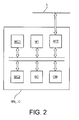
Fig. 2 schematically illustrates an element of the distribution system ofFig. 1 ; -
Fig. 3 schematically illustrates, via a block diagram, the transmission method according to the example of the invention; and -
Figs. 4 and5 schematically illustrate, via block diagrams, the method of the invention according to a further examples of the invention. - With reference to
Fig. 1 , a localenergy distribution network 100 is now described, in which a message transmission method is implementable according to an example of the invention. - By local energy distribution network is meant a portion of an energy distribution network representative of a local use area, for example a city district or area, of the energy supply (for example, electricity or gas).
- The local
energy distribution network 100 comprises a first electronic device C and at least one second electronic device MSi which are operatively mutually connected through a power line communication L. - It is pointed out that the
local distribution network 100 may comprise a plurality of electronic devices PD, which are operatively connected to the power line communication L, each of which, as it will be described herein below, is to be considered as completely similar to the second device MSi. - For the sake of simplicity, the plurality of electronic devices PD illustrated in
Fig. 1 comprises a third MSj and a fourth MSk electronic device, beside the already mentioned second electronic device MSi. - The first electronic device C comprises, for example, a network concentrator arranged to be operatively connected also to a central unit (not shown in the Figure) of the operator of the energy distribution network through a further dedicated power line communication (also not shown). The network concentrator C typically represents the so-called energy distribution box of a district.
- The second electronic device MSi comprises an energy consumption meter preferably installed at the house or building of an user of the energy distribution network.
- At an operative level, the concentrator C results to be arranged to carry out operations such as, for example, among the most important: passage from medium voltage (some thousands of Volts received by the concentrator) to low voltage (220 V to be provided to the meter of the individual user); reception by the central unit or another network electronic device (meter or concentrator) of alarm signals (for example, voltage overload), and indication to another meter or concentrator of a respective control signal preventively intended to electrically insulate a meter from the rest of the energy distribution network; reception from the meters of information relative to the respective energy consumption and transmission thereof to the central unit of the operator of the energy distribution network (concentrator acting as a repeater).
- At the operative level, instead, the individual meter (for example, the second device MSi) results to be arranged to carry out operations such as, among the most important: providing information relative to the energy consumptions to the concentrator; generating optional alarm signals representative of voltage overloads or electrical failures.
- It shall be further noticed that, advantageously, both the first electronic device C and the second electronic device MSi result to be configured to implement the transmission method in accordance to the example according to the invention that will be described herein below.
- With particular reference now to
Fig. 2 , the hardware structure of the first electronic device C is now schematically described. - The first electronic device C comprises a first microprocessor MC1 and a first memory M1 (of the RAM type) to implement and load, respectively, program codes for the carrying out of operations for which the first electronic device has been configured.
- In order to increase the performance thereof, the first electronic device C further comprises a further processor MC2, for example, a DSP (Digital Signal Processor), and a memory controller CM arranged for the management of the first memory M1 and further memories (not shown in the Figure) with which the first electronic device C can be provided or to which it can be connected.
- It is pointed out that for the implementation of the transmission method according to the example of the invention which will be described herein below, the first electronic device C results to be configured to implement, from a software point of view (through the use, for example, of the first microprocessor MC1 and the first memory M1), an encryption algorithm, for example, an AES (Advanced Encryption Standard) algorithm, per se known, or a DES (Data Encryption Standard) algorithm, also known to those skilled in the art.
- In a further embodiment, alternative to the just described one, the first electronic device C further comprises a cipher block BC arranged for the so-called implementation in hardware of the encryption algorithm (AES or DES).
- The first electronic device C further comprises a per se known analog-to-digital conversion block AFE to allow the first electronic device C, arranged to process signals in a digital format, to provide signals in an analogical format to the power line communication L.
- It shall be noticed that the example of hardware structure schematically described with reference to
Fig. 2 substantially applies also to the second electronic device MSi, since it results to be completely similar to the first electronic device C, except for the fact that it results to be free from optional connections to the second power line communication which is used, as already stated before, by the first electronic device C (concentrator) for the transmission of information to the central unit of the energy distribution network. - With reference now to
Figs. 3 and4 , amessage transmission method 200 between the first electronic device C and the second electronic device MSi according to an example of the invention is now described. - For the purposes of the present description, by message is meant a piece of information representative, for example, of the status of the energy distribution (for example, voltage overload), of the status of an electronic device connected thereto (meter or concentrator), or the energy consumption of a meter.
- The
transmission method 200 comprises a first symbolicinitial step 201, also indicated with the reference STR. - The
transmission method 200 further comprises a step of, implementing an encryption algorithm, generating 202, by the first electronic device C, a first data encryption key Ki identifying the second electronic device MSi on the basis of a main data encryption key MK and a identification code IDi of the second electronic device MSi. - The generating
step 202 of the first encryption key can be symbolically expressed by the following relationship:
in which Ki represents the first data encryption key identifying the second electronic device MSi; MK represents the main encryption key which is known to the first electronic device C; IDi represents the identification code of the second electronic device MSi, the acronym AES symbolically indicates the use of an encryption algorithm of the AES type. - As already stated before, also other encryption algorithms such as, for example, a DES-type algorithm, can be employed alternatively to the encryption AES algorithm.
- As already stated before with reference to
Fig. 2 , the encryption algorithm is implemented in hardware by the cipher block AES with which the first electronic device C is provided. - Alternatively, the first electronic device C can be configured to implement the encryption AES algorithm via software.
- Referring back to the generating
step 202 of the first data encryption key Ki, it shall be noticed that the main data encryption key MK is typically associated to the first electronic device C in the manufacturing step, therefore it is known only to the first electronic device C. - The identification code IDi of the second electronic device MSi is typically an identification code associated and assigned to the relative electronic device (meter) during the manufacturing step.
- Further, this identification code results to be known also to the first electronic device C (concentrator) following the installation in field of the second electronic device, i.e., when the second electronic device (meter) will result to be operatively associated to the first electronic device C (concentrator) through the power line communication L.
- It shall be further noticed that the first data encryption key Ki also is associated to the second electronic device MSi during the manufacturing step of the same electronic device.
- The generating
step 202 of the above-described first data encryption key advantageously allows the first electronic device C (concentrator) to avoid the storing of the encryption key of all the electronic devices similar to the second electronic device MSi connected thereto, but to be able to generate the first data encryption key Ki identifying the second electronic device MSi at the moment of the message transmission. - It shall be further noticed that, since the first electronic device has a hardware structure which is completely similar to a conventional electronic computer (
Fig. 2 ), the implementation of the encryption AES algorithm for the generation of the first data encryption key Ki results to be rather simple and rapid from a computational point of view. - In order to increase transmission safety between the first electronic device C and the second electronic device MSi, the
transmission method 200 further comprises, employing the above-mentioned encryption AES algorithm, a generatingstep 203, by the first electronic device C and the second electronic device MSi, of a communication key Kdi on the basis of the first data encryption key Ki and a reference datum DT. - The generating
step 203 can be symbolically expressed also by the following relationship:
in which Kdi represents the communication key to be used for the transmission between the first C and the second MSi electronic devices; Ki represents the first data encryption key; DT represents a reference datum (which will be dealt with herein below), and the acronym AES indicates the use of an encryption algorithm of the AES type. - As regards the reference datum DT, it comprises, for example, a temporal reference representative of the moment in which the generation (or derivation) of the data communication key Kdi occurs, both by the first electronic device C and by the second electronic device MSi.
- Such temporal reference can be, for example, the year, month, day, the complete date (in terms of day, month, or year), or time (in terms of hours, minutes, and seconds).
- In an alternative embodiment to the just described one, the reference datum DT may comprise a numeral reference obtained as a combination of two or more temporal references described before.
- Combination examples of temporal references to generate the numeral reference which can be used by the described method as the reference datum DT can be, with reference again to the moment in which the generation of the data communication key Kdi occurs: combination of year and month; combination of day and month; combination of date and time; combination of one of the above-mentioned temporal references and a numeric constant.
- It is pointed out that the data communication key Kdi preferably comprises a further message encryption key arranged to advantageously carry out a warranty function of the confidentiality of the content of the same message. A message the confidentiality of which is intended to be maintained can be, for example, a piece of information relative to the energy consumption in a consumption meter.
- In this embodiment, following the generating
step 203 of the data communication key Kdi, thetransmission method 200 further comprises theencrypting step 204 of the message to be transmitted through said further data encryption key Kdi, preferably by implementing the encryption AES algorithm. - In a further alternative embodiment to the just described one (
Fig. 4 ), the data communication key Kdi comprises a message integrity key arranged to advantageously carry out a warranty function of the integrity of the message to be transmitted. A message of which it is the integrity that is intended to be maintained, but not necessarily the confidentiality as well, can be, for example, a piece of information representative of a control signal which the first electronic device C (concentrator) sends to the second electronic device MSi (meter) with the purpose to temporarily disconnect the meter itself from the local distribution network, in order to avoid an electrical failure thereof. - In more detail, the message integrity key allows encrypting, by employing the encryption algorithm, a detection code to be associated to the message to be transmitted, typically at the foot thereof.
- As it is known, the receiving electronic device (for example, the second electronic device MSi), once the message transmitted with the encrypted detection code at the foot thereof has been received from the transmitting electronic device (for example, the first electronic device C), results to be arranged to decrypt the encrypted detection code through the integrity key Kdi. In the case where the decrypted detection code is the same as that used by the first electronic device, the message results not to be altered by an attacker, and therefore it can be considered as intact.
- It is pointed out that for the encryption of the detection code, an encryption algorithm of the AES type or of the AES CBC-MAC (Cipher Block Chaining Message Authentication Code) type, also per se known, can be employed.
- In this particular embodiment, as shown in
Fig. 4 , thetransmission method 200 therefore comprises an encryptingstep 206 of a message detection key through the integrity key Kdi, and an associatingstep 207 of the encrypted detection code to the message to be transmitted. - With reference now to the embodiment of
Fig. 5 , themethod 200 of the invention can further comprise a generating step 204', implementing the same encryption AES algorithm, by the first electronic device C and the second electronic device MSi, of a further data communication key Kdi' on the basis of the first encryption key Ki and a further reference datum UDT which is distinct from the reference datum DT described before with reference to the generatingstep 203 of the communication key Kdi. - The generating step 204' can be symbolically expressed by the following relationship:

in which Kdi, represents the further data communication key; Ki represents the first data encryption key generated in theprevious generating step 203, and UDT represents the further reference datum. - The further data communication key Kdi' will be used by both the first electronic device C and the second electronic device MSi to encrypt (step 204) the message to be transmitted through the encryption algorithm (for example, of the AES type), in the case where the data communication key Kdi is used for the message integrity as described before.
- It shall be further noted that, for the embodiment of
Fig. 5 , again the encryptingstep 206 of the message detection key and the associatingstep 207 of the encrypted detection code to the message to be transmitted, already described before, are present. - It is pointed out that this embodiment advantageously allows further increasing the message transmission safety between the first electronic device C and the second electronic device MSi, since the further data communication key Kdi is generated and employed to ensure the message integrity, and the data communication key Kdi is generated and employed to contextually ensure also the message confidentiality.
- As regards the further reference datum UDT, it shall be noticed that it results to be of the same type of the temporal datum DT, that is, it is implemented by a temporal reference representative of the moment in which the generation (or derivation) of the further data communication key Kdi' occurs, by both the first electronic device C and the second electronic device MSi.
- Such temporal reference can be, for example, the year, month, day, the complete date (in terms of day, month, or year), or time (in terms of hours, minutes, and seconds).
- In an alternative embodiment, the further reference datum UDT can comprise a numeral reference obtained as a combination or processing of one or more temporal references described before.
- Combination or processing examples of temporal references to generate the numeral reference which can be used by the described method as the further reference datum UDT can be, with reference again to the moment in which the generation of the data communication key Kdi occurs: combination of year and month; combination of day and month; combination of date and time; combination of one of the above-mentioned temporal references and a numeric constant.
- For the purposes of the present invention, with the purpose of ensuring a reliable safely level in the transmission of the message between the first electronic device C and the second device MSi, which is the most reliable possible, the further temporal datum UDT results to be preferably distinct from the temporal datum DT.
- With the term "distinct" is meant that the further reference datum UDT results to be different from the reference datum DT.
- Some examples of reference datum DT and further reference datum UDT are:
- UDT = date, DT = month;
- UDT = date, DT = time;
- UDT = date and time combination, DT date and constant combination;
- UDT = time and constant combination, DT = year and constant combination;
- and so on.
- Referring back to the
transmission method 200 with reference both to the embodiment ofFig. 3 and the embodiment ofFig. 4 , it further comprises a symbolicfinal step 205, also indicated with the symbolic reference ED. - As it can be noticed, the object of the invention results to be fully achieved, since the described transmission method, in the case where the data communication key is employed as the message encryption key, allows the first electronic device (C) and the second electronic device (MSi) to be able to encrypt the message through the data communication key (Kdi), without needing to share a priori the knowledge of the above-mentioned data communication key. The same considerations can be stated in the case, instead, that the data communication key is not employed to ensure the message confidentiality, but in order to ensure the integrity thereof (data communication key as a message integrity key).
- Furthermore, the fact that the data communication key (Kdi) is generated (or derived) by the first and the second electronic devices on the basis of a reference datum (DT), which depends on the moment in which the message transmission occurs, advantageously allows reducing the risks for the integrity of the data to be transmitted, increasing the robustness of the energy distribution network as regards the communication of the data pertaining both to the consumption on the network and the control of the same network.
- In fact, in the case where an attacker succeeds in accessing a data communication key (Kdi), he/she will be capable of retrieving the content of the encrypted message only with that data communication key (Kdi) which, as stated before, has been generated as a function of a reference datum (DT) as a function of a predetermined transmission moment, but not as a function of the previous or successive transmission moment. Therefore, the attacker won't be able to retrieve other messages any longer by employing the same data communication key (Kdi).
- Further, the embodiment of the transmission method which further comprises a generation (or derivation) step of a further data communication key (Kdi') on the basis of the first data encryption key (Ki) and on the basis of a further reference datum (UDT) which is distinct from the previous reference datum (DT, used to generate the previous data communication key) advantageously allows increasing the safety and robustness of the transmission of messages between the first and the second electronic devices, since both a confidentiality level (employing the further data communication key Kdi') and an integrity level (employing the data communication key Kdi) of the message to be transmitted are brought in.
- In fact, an attacker's task results to be still more difficult, since the introduction of a further reference datum (UDT) increases the interception degree of the message. In other terms, in the case where the data communication key (Kdi) is intercepted, it will result that, upon reception, the message could not be intact, but it will not be able to be retrieved, since the latter will be encrypted with the further data communication key (Kdi'). Furthermore, although an attacker succeeds in retrieving the reference datum (DT) with which the data communication key (Kdi) has been generated, in no event he/she will be able to get the further data communication key (Kdi'), since it has been generated (or derived) on the basis of a further reference datum (UDT) which is distinct from the reference datum (DT) that he/she is in possession of.
- Finally, it has to be also taken into account that the use, as the reference datum (DT) and as the further reference datum DT), not of the simple temporal references (year, month, date, or time), but of numeric references obtained as a combination of temporal references or as a combination of temporal references with one or more additional numeric constants, further increases the interception difficulty of the message by an attacker, and consequently the reliability and robustness of the transmission of messages between the first and the second electronic devices.
- To the above-described embodiments of the method, those of ordinary skill in the art, in order to meet contingent needs, will be able to make modifications, adaptations, and replacements of elements with other functionally equivalent ones, without departing from the scope of the following claims. Ea c h of the characteristics described as belonging to a possible embodiment can be implemented independently of the other embodiments described.
Claims (13)
- A transmission method (200) of a message between a first electronic device (C) and a second electronic device (MSi), comprising steps of:- implementing an encryption algorithm, generating (202), by the first electronic device (C), a first data encryption key (Ki) identifying the second electronic device (MSi) on the basis of a main data encryption key (MK) and an identification code (IDi) of the second electronic device (MSi);- implementing said encryption algorithm, generating (203), by the first electronic device (C) and the second electronic device (MSi), a communication key (Kdi) on the basis of said first data encryption key (Ki) and a reference datum (DT).
- The transmission method (200) according to claim 1, wherein said data communication key comprises a further data encryption key, said method further comprising, by implementing said encryption algorithm, the encrypting step (204) of said message to be transmitted through said further data encryption key (Kdi).
- The transmission method (200) according to claim 1, wherein said data communication key (Kdi) comprises a message integrity key, said method (200) further comprising the encrypting step (206), employing said encryption algorithm, of a message detection key.
- The transmission method (200) according to claim 3, further comprising the associating step (207) of said encrypted detection code to the message to be transmitted.
- The transmission method (200) according to claim 4, wherein said encrypting step (204) further comprises, implementing said encryption algorithm, the generating step (208), by the first electronic device (C) and the second electronic device (MSi), of at least one further data communication key (Kdi') on the basis of said data encryption key (Ki) and a further reference datum (UDT) distinct from said reference datum (DT).
- The transmission method (200) according to claim 5, further comprising, implementing said encryption algorithm, the encrypting step (204) of said message through said further data encryption key (Kdi').
- The transmission method (200) according to claim 5, wherein said reference datum (DT) and said further reference datum (UDT) comprise a temporal reference belonging to the group comprising: year, month, date, time.
- The transmission method (200) according to claim 5, wherein said reference datum (DT) and said further reference datum (UDT) comprise a numeral reference obtained as a combination of one or more temporal references, each of said temporal references belonging to the group comprising: year, month, date, time.
- The transmission method (200) according to claim 7, wherein said reference datum (DT) and said further reference datum (UDT) comprise a numeral reference obtained as a combination of a temporal reference with a numeric constant.
- The transmission method (200) according to claim 1, wherein said encryption algorithm is an encryption algorithm implemented via software, said encryption algorithm belonging to the group: Advanced Encryption Standard (AES), Data Encryption Standard (DES).
- The transmission method (200) according to claim 1, wherein said encryption algorithm is an encryption algorithm implemented in hardware by a cipher block (BC), said encryption algorithm being of the type belonging to the group.
- The transmission method (200) according to claim 1, wherein said encryption algorithm comprises an encryption algorithm belonging to the group: Advanced Encryption Standard (AES), Data Encryption Standard (DES).
- A local energy distribution network, comprising a first electronic device (C) and at least one second electronic device (MSi) which are operatively mutually connected through a power line communication (1), in which:the first electronic device (C) comprises a concentrator;said at least one electronic device (MSi) comprising an energy consumption meter;said first (C) and second (MSi) electronic devices being configured to implement the transmission method according to at least one of the preceding claims.
Applications Claiming Priority (1)
| Application Number | Priority Date | Filing Date | Title |
|---|---|---|---|
| IT002309A ITMI20082309A1 (en) | 2008-12-23 | 2008-12-23 | METHOD OF TRANSMISSION OF A MESSAGE, PREFERABLY FOR AN ENERGY DISTRIBUTION NETWORK |
Publications (1)
| Publication Number | Publication Date |
|---|---|
| EP2202911A1 true EP2202911A1 (en) | 2010-06-30 |
Family
ID=41680303
Family Applications (1)
| Application Number | Title | Priority Date | Filing Date |
|---|---|---|---|
| EP09178947A Withdrawn EP2202911A1 (en) | 2008-12-23 | 2009-12-11 | Key derivation by means of message authentication code for encrypting data transmission in energy distribution network |
Country Status (3)
| Country | Link |
|---|---|
| US (1) | US8331565B2 (en) |
| EP (1) | EP2202911A1 (en) |
| IT (1) | ITMI20082309A1 (en) |
Cited By (1)
| Publication number | Priority date | Publication date | Assignee | Title |
|---|---|---|---|---|
| CN110460446A (en) * | 2019-07-10 | 2019-11-15 | 北京信安世纪科技股份有限公司 | The acquisition methods and device of message authentication code |
Families Citing this family (2)
| Publication number | Priority date | Publication date | Assignee | Title |
|---|---|---|---|---|
| JP2013539295A (en) * | 2010-10-15 | 2013-10-17 | サーティコム コーポレーション | Authenticated encryption of digital signatures with message recovery |
| CA2806357C (en) * | 2010-10-15 | 2015-03-03 | Certicom Corp. | Authenticated encryption for digital signatures with message recovery |
Citations (1)
| Publication number | Priority date | Publication date | Assignee | Title |
|---|---|---|---|---|
| US20060010324A1 (en) * | 2004-07-09 | 2006-01-12 | Guido Appenzeller | Secure messaging system with derived keys |
-
2008
- 2008-12-23 IT IT002309A patent/ITMI20082309A1/en unknown
-
2009
- 2009-10-13 US US12/578,029 patent/US8331565B2/en active Active - Reinstated
- 2009-12-11 EP EP09178947A patent/EP2202911A1/en not_active Withdrawn
Patent Citations (1)
| Publication number | Priority date | Publication date | Assignee | Title |
|---|---|---|---|---|
| US20060010324A1 (en) * | 2004-07-09 | 2006-01-12 | Guido Appenzeller | Secure messaging system with derived keys |
Non-Patent Citations (2)
| Title |
|---|
| SEDOYEKA E ET AL: "WiMAX Mesh networks for underserved areas", COMPUTER SYSTEMS AND APPLICATIONS, 2008. AICCSA 2008. IEEE/ACS INTERNATIONAL CONFERENCE ON, IEEE, PISCATAWAY, NJ, USA, 31 March 2008 (2008-03-31), pages 1070 - 1075, XP031245089, ISBN: 978-1-4244-1967-8 * |
| TREYTL A ET AL: "Practical Issues on Key Distribution in Power Line Networks", 10TH IEEE INTERNATIONAL CONFERENCE ON EMERGING TECHOLOGIES AND FACTORY AUTOMATION, IEEE, PISCATAWAY, NJ, USA, vol. 2, 19 September 2005 (2005-09-19), pages 83 - 90, XP010905471, ISBN: 978-0-7803-9401-8 * |
Cited By (2)
| Publication number | Priority date | Publication date | Assignee | Title |
|---|---|---|---|---|
| CN110460446A (en) * | 2019-07-10 | 2019-11-15 | 北京信安世纪科技股份有限公司 | The acquisition methods and device of message authentication code |
| CN110460446B (en) * | 2019-07-10 | 2022-03-18 | 北京信安世纪科技股份有限公司 | Method and device for acquiring message authentication code |
Also Published As
| Publication number | Publication date |
|---|---|
| ITMI20082309A1 (en) | 2010-06-24 |
| US8331565B2 (en) | 2012-12-11 |
| US20100158250A1 (en) | 2010-06-24 |
Similar Documents
| Publication | Publication Date | Title |
|---|---|---|
| US10375040B2 (en) | Utility meter for metering a utility consumption and optimizing upstream communications and method for managing these communications | |
| CN103618610A (en) | Information safety algorithm based on energy information gateway in smart power grid | |
| KR102236235B1 (en) | The disaster broadcasting PA in public facility, the remotely functioning A/V smart broadcasting device, a closed network system | |
| CN106685775A (en) | Self-inspection type invasion prevention method and system for intelligent household electrical appliance | |
| US8331565B2 (en) | Message transmission method, preferably for an energy distribution network | |
| KR20190047477A (en) | Security key distribution method for the security reinforce of smart city cobination management system and attacker abnormal behavior detection method using the same | |
| EP3910873B1 (en) | Key-management for advanced metering infrastructure | |
| CN105991649B (en) | A kind of scheduling system of reading identity card | |
| EP3729850B1 (en) | A method for controlling by a server the use of at least one data element of a data owner | |
| CN118590303A (en) | VPN communication link encryption method, device and medium based on key negotiation | |
| KR20170002177A (en) | Apparatus and method for updating master-key on automatic meter reading network | |
| CN106027471B (en) | Scheduling server applied to identity card reading | |
| JP6491162B2 (en) | Data transmission / reception method and sensing system | |
| CN105991648B (en) | A kind of dispatching method of reading identity card | |
| Chatterjee et al. | Enhancement of Data Security Scheme with Cryptography Training System in Smart Grid Network | |
| Salpekar | Protecting smart grid and advanced metering infrastructure | |
| Baoyi et al. | Research on WSN secure communication method based on digital watermark for the monitoring of electric transmission lines | |
| Guo et al. | Cyber-physical authentication for metro systems | |
| KR20220072698A (en) | Energy cloud system using energy object data | |
| CN121194087B (en) | A method for sending meter reading information and a meter transmission system | |
| GB2607298A (en) | Smart meter device refurbishment | |
| Xu et al. | Research on Interactive Communication Information Security between Residents and Power Grid | |
| CN118611859A (en) | Transmission method, device, storage medium and computer equipment for power grid operation data | |
| CN118921207A (en) | Substation data encryption method, transmission system, equipment and medium based on environment monitoring | |
| Krempels et al. | Communication Reduced Interaction Protocol between Customer, Charging Station, and Charging Station Management System. |
Legal Events
| Date | Code | Title | Description |
|---|---|---|---|
| PUAI | Public reference made under article 153(3) epc to a published international application that has entered the european phase |
Free format text: ORIGINAL CODE: 0009012 |
|
| AK | Designated contracting states |
Kind code of ref document: A1 Designated state(s): AT BE BG CH CY CZ DE DK EE ES FI FR GB GR HR HU IE IS IT LI LT LU LV MC MK MT NL NO PL PT RO SE SI SK SM TR |
|
| AX | Request for extension of the european patent |
Extension state: AL BA RS |
|
| 17P | Request for examination filed |
Effective date: 20101220 |
|
| 17Q | First examination report despatched |
Effective date: 20110120 |
|
| STAA | Information on the status of an ep patent application or granted ep patent |
Free format text: STATUS: THE APPLICATION IS DEEMED TO BE WITHDRAWN |
|
| 18D | Application deemed to be withdrawn |
Effective date: 20110802 |