EP2202529A2 - Twisted-pair electrical cable testing - Google Patents
Twisted-pair electrical cable testing Download PDFInfo
- Publication number
- EP2202529A2 EP2202529A2 EP09252878A EP09252878A EP2202529A2 EP 2202529 A2 EP2202529 A2 EP 2202529A2 EP 09252878 A EP09252878 A EP 09252878A EP 09252878 A EP09252878 A EP 09252878A EP 2202529 A2 EP2202529 A2 EP 2202529A2
- Authority
- EP
- European Patent Office
- Prior art keywords
- magnetic field
- electrical cable
- cable
- relative motion
- twisted
- Prior art date
- Legal status (The legal status is an assumption and is not a legal conclusion. Google has not performed a legal analysis and makes no representation as to the accuracy of the status listed.)
- Granted
Links
Images
Classifications
-
- G—PHYSICS
- G01—MEASURING; TESTING
- G01R—MEASURING ELECTRIC VARIABLES; MEASURING MAGNETIC VARIABLES
- G01R31/00—Arrangements for testing electric properties; Arrangements for locating electric faults; Arrangements for electrical testing characterised by what is being tested not provided for elsewhere
- G01R31/50—Testing of electric apparatus, lines, cables or components for short-circuits, continuity, leakage current or incorrect line connections
- G01R31/58—Testing of lines, cables or conductors
- G01R31/59—Testing of lines, cables or conductors while the cable continuously passes the testing apparatus, e.g. during manufacture
-
- G—PHYSICS
- G01—MEASURING; TESTING
- G01R—MEASURING ELECTRIC VARIABLES; MEASURING MAGNETIC VARIABLES
- G01R31/00—Arrangements for testing electric properties; Arrangements for locating electric faults; Arrangements for electrical testing characterised by what is being tested not provided for elsewhere
- G01R31/08—Locating faults in cables, transmission lines, or networks
- G01R31/081—Locating faults in cables, transmission lines, or networks according to type of conductors
- G01R31/083—Locating faults in cables, transmission lines, or networks according to type of conductors in cables, e.g. underground
Definitions
- the present invention relates generally to cable inspection, and specifically to inspection of twisted-pair electrical cable.
- Wire manufacturers typically produce electrical wire in long, continuous lengths.
- the wire is normally wound on spools for sale to wire suppliers or customers. It is not uncommon for wire to break during the wire manufacturing process. When this occurs, the manufacturer usually splices the wire back together and the manufacturing process continues. When the breakage of an insulated electrical wire occurs, the manufacturer usually trims back the insulation on either side of the break and welds the two ends of the conductor together. Since it is not uncommon for several breaks to occur during a given production run, there may be several splices on a particular spool of wire, especially a spool containing several thousand feet of wire. Wire splices may also occur during insulation application, and may be caused by extrusion or tape wrapping.
- Twisted-pair cabling is a form of wiring in which two conductors, or two halves of a single circuit, are wound together for the purposes of canceling out electromagnetic interference from external sources. Twisting wires decreases interference since the loop area between the wires, which determines the magnetic coupling into the signal, is reduced. In balanced pair operation, the two wires typically carry equal and opposite signals, which are combined at the destination. Electromagnetic radiations of the wires mutually interfere and are canceled since they are 180 degrees out of phase.
- a method for cable inspection including generating a relative motion between an electrical cable including multiple wires and a magnetic field.
- An electrical signal induced in the wires is sensed and measured responsively to a magnetic field when relative motion occurs between the wire and the coil. Variations in the electrical signal are detected, wherein the variations correspond to defects in the cable.
- an apparatus for cable inspection including:
- an apparatus for cable inspection including:
- Embodiments of the present invention provide improved methods, products and systems for inspecting twisted-pair electrical cable.
- evaluation of twisted-pair electrical cable was typically performed in a destructive manner, by unraveling the cable from its shield, isolating individual pairs of twisted wires within the cable, and then counting the twists, in some cases using a microscope.
- an X-ray machine with a needle-hole anode has also been used to image twisted pairs of electrical wires within cables, but has typically been unable to display clear images of the wires due to screening of the wires by the shield and by the presence of multiple pairs of twisted wires.
- a magnetic field generator produces a concentrated magnetic field.
- a ferromagnetic torus with a gap may be driven by an excitation coil to generate a concentrated magnetic field in the gap.
- a power generator provides alternating current through an excitation coil to generate a magnetic field focus in the torus.
- the edges of the torus adjacent to the gap may be sharpened to give enhanced concentration of the lines of flux.
- other types of magnetic field generators may be used for this purpose.
- Twisted-pair electrical cable comprising multiple wires is conveyed along a path through the magnetic field focus, via the gap in the torus, for example. That is to say, a relative motion is generated between the cable and the magnetic field.
- the cable may be conveyed using an automated conveyor or may be pulled through the gap manually, and is thus subjected to the magnetic field.
- the wires of the cable are typically connected across a differential amplifier at the end of the cable, in order to amplify the differential electrical signal that is generated between the wires due to the effect of the magnetic field.
- a monitor such as an oscilloscope, is connected to the amplifier and is used to measure an electrical signal such as the net voltage induced between paired wires in the cable.
- the particular instrumentation disclosed herein is not critical, and many known monitors are suitable for continually measuring the electrical signal between the wires.
- Each paired half-twist of wires behaves as a loop antenna, and produces a voltage whose phase is opposite to that of its fellow when subjected to the magnetic field. That is to say, in a homogeneous magnetic field, the respective voltages of the paired wires normally cancel each other, producing no net voltage across the two wires.
- the monitor senses a variation in the electrical signal due to the motion, in phase with the excitation current.
- Standard twisted-pair electrical cable normally has a uniform pitch, and the voltage signal detected by the monitor should therefore have uniform amplitude and phase. However, if the twists in the cable are incorrectly spread in a non-uniform fashion at some location in the cable, the electrical signal varies from a norm as the cable is conveyed through the magnetic field. The monitor detects this variation, which is thereupon interpreted as a defect of the twisted-pair electrical cable.
- a data acquisition unit may be connected to the monitor to automatically report the electrical signal and the detection of the defect.
- Defects in twisted-pair electrical cable may be caused when the twists are unraveled during the process of shielding encapsulation. Another cause of defects is that manufacturers of twisted-pair electrical cable typically twist the bundle of paired wires in the opposite direction of the twists of the individual wire pairs. Twisting in this fashion may unravel an individual pair of wires, thus causing the effective number of twists per inch to decrease.
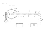
- Fig. 1 is a block diagram that schematically illustrates a system 20 for inspecting twisted-pair electrical cable, in accordance with an embodiment of the present invention.
- System 20 comprises a twisted-pair electrical cable 22, a ferromagnetic torus 24, a differential amplifier 34, and a voltage monitor 36.
- Twisted-pair electrical cable 22 comprises pairs of electrically conductive cable, wound together over the length of the cable, and coated with a shield 38.
- a current embodiment of system 20 operates effectively as long as shield 38 is not ferromagnetic. (In the case of a shield that is magnetically hardened, system 20 is typically more effective if the shield is first removed).
- Twisted-pair electrical cable 22 is typically grounded by a chassis 40.
- a magnetic field is concentrated in a gap in torus 24 by an exciting coil 32 powered by a power generator 30, producing a magnetic field focus 26.
- the edges of torus 24 may be sharpened to provide enhanced concentration of the flux lines. That is to say, a magnetic field is concentrated in a location, herein magnetic field focus 26, which is associated with a magnetic field generator. Operating the magnetic field generator produces the magnetic field.
- Twisted-pair electrical cable 22 comprising multiple wires 62, 64, has a trailing end 56, and a leading end 58. Trailing end 56 and leading end 58 are labels of twisted-pair electrical cable 22 that are assigned arbitrarily in order to denote opposite ends of the cable. Trailing end 56 of twisted-pair electrical cable 22 is "shorted," i.e., it is stripped of shield 38 and wires 62 and 64 are connected together. Leading end 58 of twisted-pair electrical cable 22 is connected to amplifier 34, completing a circuit for the purpose of monitoring the magnetic field by monitor 36.
- a suitable conveyance device shown schematically as a conveyor 27, moves twisted-pair electrical cable 22 through magnetic field focus 26, guided by diamagnetic shoulders 28.
- Diamagnetic shoulders 28 are typically made of a plastic material and guide twisted-pair electrical cable 22 precisely through magnetic field focus 26.
- the conveyance device may be conveyed manually, e.g., by a person rather than by a machine, through magnetic field focus 26.
- operation of embodiments of the present invention is not limited to a particular method of generating a relative motion between twisted-pair electrical cable 22 and magnetic field focus 26, and that any other suitable method that accomplishes relative motion of twisted-pair electrical cable 22 with respect to magnetic field focus 26 may be used.
- a movable torus could be conveyed along the cable to achieve the relative motion.
- An arrow 42 displays a direction of the movement of twisted-pair electrical cable 22. Twisted-pair electrical cable 22 is shown moving in the direction displayed by arrow 42, although embodiments of the present invention are not limited to movement in that direction.
- Monitor 36 measures an electrical signal that is induced in the wires of twisted-pair electrical cable 22 in response to relative motion between twisted-pair electrical cable 22 and magnetic field focus 26 and any signal variations thereof.
- a data acquisition unit 54 may be connected to monitor 36. Data acquisition unit 54 correlates the momentary electrical signal with locations in the electrical cable 22, and interprets certain signal variations in the monitored signal as location-specific defects in twisted-pair electrical cable 22. For example, detection of a signal variation may locate a flaw in a particular twist of the wires of twisted-pair electrical cable 22. Data acquisition unit 54 may report the defect and may also store data delineating the location of a defective part of twisted-pair electrical cable 22. Alternatively, any suitable method known in the art may be used to detect signal variations and to report defects. In the context of the present patent application and in the claims, the term "signal variation" refers to a change (typically an increase) in the amplitude of the monitored signal or to a change in the length of time between phase alternations in the monitored signal.
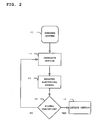
- Fig. 2 is a flow chart that schematically illustrates a method for inspecting twisted-pair electrical cable, in accordance with an embodiment of the present invention.
- twisted-pair wires 62 and 64 are shorted at trailing end 56 of twisted-pair electrical cable 22.
- Leading end 58 of twisted-pair electrical cable 22 is connected to amplifier 34, as described hereinabove.
- twisted-pair electrical cable 22 comprises multiple wires that are 40 ⁇ m in diameter, and have 15 full twists per inch.
- Shield 38 comprises a helix of ten parallel strands of silver-plated copper that are 20 ⁇ m in diameter and covers more than 90% of the surface of twisted-pair electrical cable 22, and is coated with a finish comprising a polyurethane jacket. It will be understood, however, that operation of embodiments of the present invention is not limited to a particular type of twisted-pair electrical cable, that any other suitable twisted-pair electrical cable may be tested, and that all such cable is considered to be within the scope of embodiments of the present invention.
- System preparation step 44 also comprises generation of the magnetic field in magnetic field focus 26 by activation of power generator 30 to produce a magnetic field focus 26 as described hereinabove.
- magnetic field focus 26 in the gap of torus 24 should be smaller than an effective area of each half-twist of twisted-pair electrical cable 22.
- Amplifier 34 is typically designed in conjunction with the calculated pick-up voltage from twisted-pair electrical cable 22, which is a function of the size of the cable and the magnetic flux density and frequency in the gap in torus 24.
- amplifier 34 is embodied as a low noise instrumental amplifier with a gain of approximately 2000.
- system preparation step 44 may also comprise synchronizing the oscilloscope with magnetic field generator 30. Once synchronized, the oscilloscope should display a sine wave that varies in phase between the values -180° and +180° as twisted-pair electrical cable 22 moves through magnetic field focus 26. In the present example, there are approximately 30 phase alternations per inch of twisted-pair electrical cable 22 since each inch of cable is comprised of 15 full twists, and there should be two complete phase changes in each full twist of cable.
- Twisted-pair electrical cable 22 may be moved by the conveyance device relative to magnetic field focus 26 or may be moved manually, as described hereinabove.
- Measuring occurs in an electrical signal measuring step 48.
- an oscilloscope is monitored to determine the electrical signal induced between the wires in twisted-pair electrical cable 22. If monitor 36 senses a variation in the electrical signal in a signal variation decision step 50, a defect is detected in a defect detection step 52. If the electrical signal varies, according to an application-specific criterion, as the cable is conveyed through the magnetic field, monitor 36 detects this variation, which is thereupon interpreted as a defect of twisted-pair electrical cable 22. If the electrical signal remains steady, whereby no signal variations are detected, as defined hereinabove, twisted-pair electrical wire 22 continues to move through magnetic field focus 26 in a resumption of motion generation step 46.
- data acquisition unit 54 may be synchronized to conveyor 27 of twisted-pair electrical cable 22, which may run automatically.
- Automatic conveyors that may be adapted for use in the present system are disclosed for example in US Patent No. 5,050,093 and US Patent No. 3,763,426 , which are herein incorporated by reference.
- system 20 may be used to determine the precise locations of small magnetic coils that are encased in dielectric material, such as in a plastic casing. Such a system may also be used to locate hidden wire loops in electrical cable or other circuitry, in order to find and remove sources of electrical interference. It will be appreciated by persons skilled in the art that the present invention is not limited to what has been particularly shown and described hereinabove. Rather, the scope of the present invention includes both combinations and sub-combinations of the various features described hereinabove, as well as variations and modifications thereof that are not in the prior art, which would occur to persons skilled in the art upon reading the foregoing description.
Abstract
Description
- The present invention relates generally to cable inspection, and specifically to inspection of twisted-pair electrical cable.
- Wire manufacturers typically produce electrical wire in long, continuous lengths. The wire is normally wound on spools for sale to wire suppliers or customers. It is not uncommon for wire to break during the wire manufacturing process. When this occurs, the manufacturer usually splices the wire back together and the manufacturing process continues. When the breakage of an insulated electrical wire occurs, the manufacturer usually trims back the insulation on either side of the break and welds the two ends of the conductor together. Since it is not uncommon for several breaks to occur during a given production run, there may be several splices on a particular spool of wire, especially a spool containing several thousand feet of wire. Wire splices may also occur during insulation application, and may be caused by extrusion or tape wrapping.
- Twisted-pair cabling is a form of wiring in which two conductors, or two halves of a single circuit, are wound together for the purposes of canceling out electromagnetic interference from external sources. Twisting wires decreases interference since the loop area between the wires, which determines the magnetic coupling into the signal, is reduced. In balanced pair operation, the two wires typically carry equal and opposite signals, which are combined at the destination. Electromagnetic radiations of the wires mutually interfere and are canceled since they are 180 degrees out of phase.
- In a disclosed embodiment, a method is provided for cable inspection, including generating a relative motion between an electrical cable including multiple wires and a magnetic field. An electrical signal induced in the wires is sensed and measured responsively to a magnetic field when relative motion occurs between the wire and the coil. Variations in the electrical signal are detected, wherein the variations correspond to defects in the cable.
- There is further provided, according to an embodiment of the present invention, an apparatus for cable inspection, including:
- a magnetic field generator to produce a magnetic field; and
- a monitor coupled to an electrical cable including multiple wires, the monitor being configured to detect variations in electrical signals that are produced responsively to a relative motion between the magnetic field and the electrical cable, wherein the variations correspond to defects in the cable.
- There is further provided, according to an embodiment of the present invention, an apparatus for cable inspection, including:
- a magnetic field generator to produce a magnetic field;
- a conveyor for generating a relative motion between an electrical cable including multiple wires and the magnetic field; and
- a monitor coupled to the electrical cable, the monitor being configured to detect variations in electrical signals that are produced responsively to the relative motion, wherein the variations correspond to defects in the cable.
- For a better understanding of the present invention, reference is made to the detailed description of the invention, by way of example, which is to be read in conjunction with the following drawings, wherein like elements are given like reference numerals, and wherein:
-
Fig. 1 is a block diagram that schematically illustrates a system for inspecting twisted-pair electrical cable, in accordance with an embodiment of the present invention; and -
Fig. 2 is a flow chart that schematically illustrates a method for inspecting twisted-pair electrical cable, in accordance with an embodiment of the present invention. - Embodiments of the present invention that are described hereinbelow provide improved methods, products and systems for inspecting twisted-pair electrical cable. In the past, evaluation of twisted-pair electrical cable was typically performed in a destructive manner, by unraveling the cable from its shield, isolating individual pairs of twisted wires within the cable, and then counting the twists, in some cases using a microscope. Historically, an X-ray machine with a needle-hole anode has also been used to image twisted pairs of electrical wires within cables, but has typically been unable to display clear images of the wires due to screening of the wires by the shield and by the presence of multiple pairs of twisted wires.
- In embodiments of the invention, a magnetic field generator produces a concentrated magnetic field. For example a ferromagnetic torus with a gap may be driven by an excitation coil to generate a concentrated magnetic field in the gap. A power generator provides alternating current through an excitation coil to generate a magnetic field focus in the torus. The edges of the torus adjacent to the gap may be sharpened to give enhanced concentration of the lines of flux. Alternatively, other types of magnetic field generators may be used for this purpose.
- Twisted-pair electrical cable comprising multiple wires is conveyed along a path through the magnetic field focus, via the gap in the torus, for example. That is to say, a relative motion is generated between the cable and the magnetic field. The cable may be conveyed using an automated conveyor or may be pulled through the gap manually, and is thus subjected to the magnetic field. The wires of the cable are typically connected across a differential amplifier at the end of the cable, in order to amplify the differential electrical signal that is generated between the wires due to the effect of the magnetic field.
- A monitor, such as an oscilloscope, is connected to the amplifier and is used to measure an electrical signal such as the net voltage induced between paired wires in the cable. The particular instrumentation disclosed herein is not critical, and many known monitors are suitable for continually measuring the electrical signal between the wires. Each paired half-twist of wires behaves as a loop antenna, and produces a voltage whose phase is opposite to that of its fellow when subjected to the magnetic field. That is to say, in a homogeneous magnetic field, the respective voltages of the paired wires normally cancel each other, producing no net voltage across the two wires. As the cable is pulled through the sharply focused field of the test apparatus described above, however, the monitor senses a variation in the electrical signal due to the motion, in phase with the excitation current.
- Standard twisted-pair electrical cable normally has a uniform pitch, and the voltage signal detected by the monitor should therefore have uniform amplitude and phase. However, if the twists in the cable are incorrectly spread in a non-uniform fashion at some location in the cable, the electrical signal varies from a norm as the cable is conveyed through the magnetic field. The monitor detects this variation, which is thereupon interpreted as a defect of the twisted-pair electrical cable. A data acquisition unit may be connected to the monitor to automatically report the electrical signal and the detection of the defect.
- Defects in twisted-pair electrical cable may be caused when the twists are unraveled during the process of shielding encapsulation. Another cause of defects is that manufacturers of twisted-pair electrical cable typically twist the bundle of paired wires in the opposite direction of the twists of the individual wire pairs. Twisting in this fashion may unravel an individual pair of wires, thus causing the effective number of twists per inch to decrease.
- Reference is now made to
Fig. 1 , which is a block diagram that schematically illustrates asystem 20 for inspecting twisted-pair electrical cable, in accordance with an embodiment of the present invention.System 20 comprises a twisted-pairelectrical cable 22, aferromagnetic torus 24, adifferential amplifier 34, and avoltage monitor 36. Twisted-pairelectrical cable 22 comprises pairs of electrically conductive cable, wound together over the length of the cable, and coated with ashield 38. A current embodiment ofsystem 20 operates effectively as long asshield 38 is not ferromagnetic. (In the case of a shield that is magnetically hardened,system 20 is typically more effective if the shield is first removed). Twisted-pairelectrical cable 22 is typically grounded by achassis 40. - A magnetic field is concentrated in a gap in
torus 24 by anexciting coil 32 powered by apower generator 30, producing amagnetic field focus 26. The edges oftorus 24 may be sharpened to provide enhanced concentration of the flux lines. That is to say, a magnetic field is concentrated in a location, hereinmagnetic field focus 26, which is associated with a magnetic field generator. Operating the magnetic field generator produces the magnetic field. - Twisted-pair
electrical cable 22, comprisingmultiple wires 62, 64, has a trailingend 56, and a leading end 58. Trailingend 56 and leading end 58 are labels of twisted-pairelectrical cable 22 that are assigned arbitrarily in order to denote opposite ends of the cable. Trailingend 56 of twisted-pairelectrical cable 22 is "shorted," i.e., it is stripped ofshield 38 andwires 62 and 64 are connected together. Leading end 58 of twisted-pairelectrical cable 22 is connected toamplifier 34, completing a circuit for the purpose of monitoring the magnetic field bymonitor 36. - A suitable conveyance device, shown schematically as a
conveyor 27, moves twisted-pairelectrical cable 22 throughmagnetic field focus 26, guided bydiamagnetic shoulders 28. Diamagnetic shoulders 28 are typically made of a plastic material and guide twisted-pairelectrical cable 22 precisely throughmagnetic field focus 26. In an alternative to employing the conveyance device to move twisted-pairelectrical cable 22, the cable may be conveyed manually, e.g., by a person rather than by a machine, throughmagnetic field focus 26. It will be understood, however, that operation of embodiments of the present invention is not limited to a particular method of generating a relative motion between twisted-pairelectrical cable 22 andmagnetic field focus 26, and that any other suitable method that accomplishes relative motion of twisted-pairelectrical cable 22 with respect tomagnetic field focus 26 may be used. For example, a movable torus could be conveyed along the cable to achieve the relative motion. Anarrow 42 displays a direction of the movement of twisted-pairelectrical cable 22. Twisted-pairelectrical cable 22 is shown moving in the direction displayed byarrow 42, although embodiments of the present invention are not limited to movement in that direction. -
Monitor 36 measures an electrical signal that is induced in the wires of twisted-pairelectrical cable 22 in response to relative motion between twisted-pairelectrical cable 22 andmagnetic field focus 26 and any signal variations thereof. Adata acquisition unit 54 may be connected to monitor 36.Data acquisition unit 54 correlates the momentary electrical signal with locations in theelectrical cable 22, and interprets certain signal variations in the monitored signal as location-specific defects in twisted-pairelectrical cable 22. For example, detection of a signal variation may locate a flaw in a particular twist of the wires of twisted-pairelectrical cable 22.Data acquisition unit 54 may report the defect and may also store data delineating the location of a defective part of twisted-pairelectrical cable 22. Alternatively, any suitable method known in the art may be used to detect signal variations and to report defects. In the context of the present patent application and in the claims, the term "signal variation" refers to a change (typically an increase) in the amplitude of the monitored signal or to a change in the length of time between phase alternations in the monitored signal. - Reference is now made to
Fig. 2 , which is a flow chart that schematically illustrates a method for inspecting twisted-pair electrical cable, in accordance with an embodiment of the present invention. In asystem preparation step 44, twisted-pair wires 62 and 64 are shorted at trailingend 56 of twisted-pairelectrical cable 22. (In a cable containing multiple twisted pairs, each pair of wires may be shorted and tested in the manner described herein.) Leading end 58 of twisted-pairelectrical cable 22 is connected toamplifier 34, as described hereinabove. In the present embodiment, for example, twisted-pairelectrical cable 22 comprises multiple wires that are 40 µm in diameter, and have 15 full twists per inch.Shield 38 comprises a helix of ten parallel strands of silver-plated copper that are 20 µm in diameter and covers more than 90% of the surface of twisted-pairelectrical cable 22, and is coated with a finish comprising a polyurethane jacket. It will be understood, however, that operation of embodiments of the present invention is not limited to a particular type of twisted-pair electrical cable, that any other suitable twisted-pair electrical cable may be tested, and that all such cable is considered to be within the scope of embodiments of the present invention. -
System preparation step 44 also comprises generation of the magnetic field inmagnetic field focus 26 by activation ofpower generator 30 to produce amagnetic field focus 26 as described hereinabove. For sensitive detection of defects in the cable,magnetic field focus 26 in the gap oftorus 24 should be smaller than an effective area of each half-twist of twisted-pairelectrical cable 22. The effective area of each half twist of twisted-pairelectrical cable 22 may be approximated using the following equation:
where EA is the effective area, L is the length of one complete twist, and D is the diameter of a single strand of twisted-pairelectrical cable 22 including its insulation. It is desirable that the focus of the magnetic field have a size on the order of this area. Alternatively, a less focused magnetic field, or even a homogeneous field, could be used for testing the cable. -
Amplifier 34 is typically designed in conjunction with the calculated pick-up voltage from twisted-pairelectrical cable 22, which is a function of the size of the cable and the magnetic flux density and frequency in the gap intorus 24. In the present embodiment, wherein the magnetic flux density is 50 mA at 5 KHz excitation current inexciting coil 32,amplifier 34 is embodied as a low noise instrumental amplifier with a gain of approximately 2000. - In embodiments wherein
monitor 36 comprises an oscilloscope for monitoringamplifier 34,system preparation step 44 may also comprise synchronizing the oscilloscope withmagnetic field generator 30. Once synchronized, the oscilloscope should display a sine wave that varies in phase between the values -180° and +180° as twisted-pairelectrical cable 22 moves throughmagnetic field focus 26. In the present example, there are approximately 30 phase alternations per inch of twisted-pairelectrical cable 22 since each inch of cable is comprised of 15 full twists, and there should be two complete phase changes in each full twist of cable. - Relative motion is generated between twisted-pair
electrical cable 22 andmagnetic field focus 26 in amotion generation step 46. Twisted-pairelectrical cable 22 may be moved by the conveyance device relative tomagnetic field focus 26 or may be moved manually, as described hereinabove. - Measuring occurs in an electrical
signal measuring step 48. In the present example, an oscilloscope is monitored to determine the electrical signal induced between the wires in twisted-pairelectrical cable 22. Ifmonitor 36 senses a variation in the electrical signal in a signalvariation decision step 50, a defect is detected in adefect detection step 52. If the electrical signal varies, according to an application-specific criterion, as the cable is conveyed through the magnetic field, monitor 36 detects this variation, which is thereupon interpreted as a defect of twisted-pairelectrical cable 22. If the electrical signal remains steady, whereby no signal variations are detected, as defined hereinabove, twisted-pairelectrical wire 22 continues to move throughmagnetic field focus 26 in a resumption ofmotion generation step 46. - In some embodiments wherein
data acquisition unit 54 is connected to monitor 36,data acquisition unit 54 may be synchronized toconveyor 27 of twisted-pairelectrical cable 22, which may run automatically. Automatic conveyors that may be adapted for use in the present system are disclosed for example inUS Patent No. 5,050,093 andUS Patent No. 3,763,426 , which are herein incorporated by reference. - In alternative embodiments, the principles of
system 20 may be used to determine the precise locations of small magnetic coils that are encased in dielectric material, such as in a plastic casing. Such a system may also be used to locate hidden wire loops in electrical cable or other circuitry, in order to find and remove sources of electrical interference.
It will be appreciated by persons skilled in the art that the present invention is not limited to what has been particularly shown and described hereinabove. Rather, the scope of the present invention includes both combinations and sub-combinations of the various features described hereinabove, as well as variations and modifications thereof that are not in the prior art, which would occur to persons skilled in the art upon reading the foregoing description.
Claims (17)
- A method of cable inspection comprising:generating a relative motion between an electrical cable comprising multiple wires and a magnetic field;detecting variations in electrical signals that are produced responsively to the relative motion, wherein the variations correspond to defects in the cable.
- The method according to claim 1, wherein the step of detecting variations comprising:measuring an electrical signal induced in the wires responsively to the magnetic field;sensing a variation in the electrical signal due to the relative motion; anddetecting a defect in the electrical cable responsively to the variation.
- The method according to claim 2 wherein generating the relative motion comprises operating a magnetic field generator to produce the magnetic field, the magnetic field being concentrated in a location associated with the magnetic field generator, and wherein detecting the defect comprises identifying a defective part of the electrical cable due to the variation sensed when the defective part is in the location.
- The method according to claim 3 wherein detecting the defect comprises automatically identifying the defective part of the electrical cable by a data acquisition unit connected to a monitor.
- The method according to claim 3 wherein the magnetic field generator comprises a torus having a gap therein, and wherein the magnetic field is concentrated in the gap.
- The method according to claim 5 wherein generating the relative motion comprises moving at least one of the magnetic field generator and the electrical cable so that the location is translated longitudinally along the electrical cable.
- The method according to claim 6 wherein moving the at least one of the magnetic field generator and the electrical cable comprises conveying the electrical cable through the gap.
- The method according to claim 7 wherein conveying the electrical cable is performed manually.
- The method according to claim 1 or claim 2 wherein the electrical cable comprises a twisted pair of wires.
- An apparatus for cable inspection, comprising:a magnetic field generator to produce a magnetic field; anda monitor coupled to an electrical cable comprising multiple wires, the monitor being configured to detect variations in electrical signals that are produced responsively to a relative motion between the magnetic field and the electrical cable, wherein the variations correspond to defects in the cable.
- The apparatus according to claim 10 wherein the relative motion is generated by manually drawing the cable through the magnetic field.
- An apparatus according to claim 10, further comprising:a conveyor for generating the relative motion between the electrical cable and the magnetic field.
- The apparatus according to claim 10 or claim 12, wherein the magnetic field generator is configured to concentrate the magnetic field in a location associated with the magnetic field generator.
- The apparatus according to claim 10 or claim 12, further comprising a data acquisition unit connected to the monitor that is configured to automatically identify a defective part of the electrical cable.
- The apparatus according to claim 12, wherein the magnetic field generator comprises a torus having a gap therein, and wherein the magnetic field is concentrated in the gap.
- The apparatus according to claim 13 when dependent upon claim 12, wherein the conveyor is configured to generate the relative motion by moving at least one of the magnetic field generator and the electrical cable so that the location is translated longitudinally along the electrical cable.
- The apparatus according to claim 16, wherein the conveyor is arranged so as to convey the electrical cable through the gap.
Applications Claiming Priority (1)
| Application Number | Priority Date | Filing Date | Title |
|---|---|---|---|
| US12/342,638 US8085053B2 (en) | 2008-12-23 | 2008-12-23 | Twisted-pair electrical cable testing |
Publications (3)
| Publication Number | Publication Date |
|---|---|
| EP2202529A2 true EP2202529A2 (en) | 2010-06-30 |
| EP2202529A3 EP2202529A3 (en) | 2013-12-11 |
| EP2202529B1 EP2202529B1 (en) | 2015-04-15 |
Family
ID=41716546
Family Applications (1)
| Application Number | Title | Priority Date | Filing Date |
|---|---|---|---|
| EP09252878.5A Not-in-force EP2202529B1 (en) | 2008-12-23 | 2009-12-22 | Twisted-pair electrical cable testing |
Country Status (7)
| Country | Link |
|---|---|
| US (1) | US8085053B2 (en) |
| EP (1) | EP2202529B1 (en) |
| JP (1) | JP5484885B2 (en) |
| CN (1) | CN101762770B (en) |
| AU (1) | AU2009243516B2 (en) |
| CA (1) | CA2688905C (en) |
| IL (1) | IL202902A (en) |
Cited By (1)
| Publication number | Priority date | Publication date | Assignee | Title |
|---|---|---|---|---|
| EP2851695A1 (en) * | 2013-09-24 | 2015-03-25 | Siemens Aktiengesellschaft | Partial continuity test for stator bars of electrical machines |
Families Citing this family (4)
| Publication number | Priority date | Publication date | Assignee | Title |
|---|---|---|---|---|
| CN109839605B (en) * | 2019-02-23 | 2020-06-23 | 中国原子能科学研究院 | Cable structure of high-precision magnetic field measurement induction coil |
| US11629412B2 (en) | 2020-12-16 | 2023-04-18 | Rolls-Royce Corporation | Cold spray deposited masking layer |
| CN113075584B (en) * | 2021-04-15 | 2022-01-14 | 哈尔滨理工大学 | Method for detecting strand short circuit fault of stator transposition wire rod |
| CN114019318B (en) * | 2022-01-06 | 2022-03-18 | 山东广域科技有限责任公司 | Indicator for sectional positioning of power line fault |
Citations (2)
| Publication number | Priority date | Publication date | Assignee | Title |
|---|---|---|---|---|
| US3763426A (en) | 1972-03-07 | 1973-10-02 | Hipotronics | Method and apparatus for testing twisted pair wire to locate electrical insulation faults or measure twist or wire runout or sense breaks in the conductors |
| US5050093A (en) | 1989-10-19 | 1991-09-17 | The Boeing Company | Method and apparatus for inspecting electrical wire |
Family Cites Families (16)
| Publication number | Priority date | Publication date | Assignee | Title |
|---|---|---|---|---|
| US3252085A (en) * | 1963-09-12 | 1966-05-17 | Western Electric Co | Method of locating coaxial cable arcing faults utilizing a magnetic blowout principle |
| GB1067769A (en) * | 1965-01-04 | 1967-05-03 | Unisearch Ltd | Search coil for non-destructive testing of wire ropes and similarly shaped objects |
| US3628133A (en) * | 1970-06-29 | 1971-12-14 | Western Electric Co | Methods of and apparatus for detecting and locating opens in conductors including a signal generator movable with the conductors |
| US3988666A (en) * | 1976-01-12 | 1976-10-26 | Southwire Company | Multiplex cable insulation fault locator system with electrical conducting guides mounted on a rotating disc |
| DE2606504C3 (en) * | 1976-02-18 | 1978-08-17 | Siemens Ag, 1000 Berlin Und 8000 Muenchen | Method and device for the continuous, non-contact testing of an elongated conductor consisting at least partially of superconductor material |
| JPS5823684B2 (en) * | 1978-12-21 | 1983-05-17 | 株式会社フジクラ | Method for detecting defective wire arrangement within a cable tie when twisting cables together |
| US4241304A (en) * | 1979-05-09 | 1980-12-23 | Clinton Henry H | Continuous continuity monitor for monitoring the continuity of an insulated wire conductor |
| JPS57199966A (en) * | 1981-06-03 | 1982-12-08 | Fujikura Ltd | Detecting method for failure in array of core in quad of quad cable |
| FI84108C (en) * | 1987-11-23 | 1991-10-10 | Elecid Ab Oy | FOERFARANDE OCH ANORDNING FOER LOKALISERING AV KABELFEL. |
| FI84302C (en) * | 1989-04-25 | 1991-11-11 | Tipteck Oy | Method and apparatus for locating a ground or water submerged cable or cable fault from the ground or above water |
| CA2054797A1 (en) * | 1990-11-07 | 1992-05-08 | Nicolaas T. Van Der Walt | Electro-magnetic testing of wire ropes |
| CN2157517Y (en) * | 1993-07-09 | 1994-02-23 | 韩文彬 | Wire rope flaw detector |
| FR2710156B3 (en) * | 1993-09-14 | 1996-03-01 | Excem | Device for the characterization of imperfections of cable screens with screen by application of a variable magnetic field transverse to the axis of the cable. |
| US6281685B1 (en) * | 1995-08-29 | 2001-08-28 | The United States Of America As Represented By The Secretary Of The Army | Cable shield fault locator |
| JPH10125151A (en) * | 1996-10-18 | 1998-05-15 | Sumitomo Wiring Syst Ltd | Stranding period detecting method for stranded cable |
| JP3285568B2 (en) * | 1999-05-24 | 2002-05-27 | 日本電産リード株式会社 | Board wiring inspection apparatus and wiring inspection method |
-
2008
- 2008-12-23 US US12/342,638 patent/US8085053B2/en not_active Expired - Fee Related
-
2009
- 2009-12-04 AU AU2009243516A patent/AU2009243516B2/en not_active Ceased
- 2009-12-18 CA CA2688905A patent/CA2688905C/en not_active Expired - Fee Related
- 2009-12-21 JP JP2009288988A patent/JP5484885B2/en not_active Expired - Fee Related
- 2009-12-22 EP EP09252878.5A patent/EP2202529B1/en not_active Not-in-force
- 2009-12-22 IL IL202902A patent/IL202902A/en not_active IP Right Cessation
- 2009-12-23 CN CN200910261930.1A patent/CN101762770B/en not_active Expired - Fee Related
Patent Citations (2)
| Publication number | Priority date | Publication date | Assignee | Title |
|---|---|---|---|---|
| US3763426A (en) | 1972-03-07 | 1973-10-02 | Hipotronics | Method and apparatus for testing twisted pair wire to locate electrical insulation faults or measure twist or wire runout or sense breaks in the conductors |
| US5050093A (en) | 1989-10-19 | 1991-09-17 | The Boeing Company | Method and apparatus for inspecting electrical wire |
Cited By (5)
| Publication number | Priority date | Publication date | Assignee | Title |
|---|---|---|---|---|
| EP2851695A1 (en) * | 2013-09-24 | 2015-03-25 | Siemens Aktiengesellschaft | Partial continuity test for stator bars of electrical machines |
| WO2015043942A1 (en) | 2013-09-24 | 2015-04-02 | Siemens Aktiengesellschaft | Interstrand short circuit testing of stator winding bars of electric machines |
| CN105593692A (en) * | 2013-09-24 | 2016-05-18 | 西门子公司 | Interstrand short circuit testing of stator winding bars of electric machines |
| CN105593692B (en) * | 2013-09-24 | 2018-10-19 | 西门子公司 | The sub- conductor test for short-circuit of the stator bars of motor |
| US10107852B2 (en) | 2013-09-24 | 2018-10-23 | Siemens Aktiengesellschaft | Interstrand short circuit testing of stator winding bars of electric machines |
Also Published As
| Publication number | Publication date |
|---|---|
| CN101762770A (en) | 2010-06-30 |
| AU2009243516A1 (en) | 2010-07-08 |
| US20100156431A1 (en) | 2010-06-24 |
| JP2010151816A (en) | 2010-07-08 |
| IL202902A (en) | 2013-01-31 |
| AU2009243516B2 (en) | 2013-10-10 |
| CN101762770B (en) | 2015-09-09 |
| EP2202529B1 (en) | 2015-04-15 |
| JP5484885B2 (en) | 2014-05-07 |
| US8085053B2 (en) | 2011-12-27 |
| EP2202529A3 (en) | 2013-12-11 |
| CA2688905A1 (en) | 2010-06-23 |
| CA2688905C (en) | 2016-09-06 |
Similar Documents
| Publication | Publication Date | Title |
|---|---|---|
| US5068608A (en) | Multiple coil eddy current probe system and method for determining the length of a discontinuity | |
| EP2202529B1 (en) | Twisted-pair electrical cable testing | |
| CA2208994C (en) | Cable partial discharge location pointer | |
| US6809523B1 (en) | On-line detection of partial discharge in electrical power systems | |
| EP1153289B1 (en) | Eddy current testing with compact configuration | |
| EP0239537B1 (en) | Method of and apparatus for testing a wire rope | |
| GB2475315A (en) | Apparatus and method for inspection of components made of electrically conductive material by partial saturation eddy current testing | |
| US5760590A (en) | Cable integrity tester | |
| US6377040B1 (en) | Eddy current probe and process for checking the edges of metal articles | |
| CN106680649A (en) | Nuclear power plant earth fault detecting method and device | |
| EP2690433A1 (en) | Broadband eddy current probe | |
| CN106716153B (en) | Signal processing of partial discharge device | |
| US3860866A (en) | Methods and apparatus for locating an open section in a conductor | |
| CN109073606B (en) | Rope damage diagnosis and inspection device | |
| EP2818856B1 (en) | Eddy-current inspection method and device | |
| JP2019032209A (en) | Fiber-reinforced composite cable inspection method and inspection device | |
| JP7081446B2 (en) | Magnetic material inspection device and magnetic material inspection system | |
| JP6373471B1 (en) | Inspection method and inspection apparatus for fiber reinforced composite cable | |
| JP3223991U (en) | Nondestructive inspection equipment | |
| CN113267116B (en) | System and method for measuring length of coiled cable | |
| KR101043319B1 (en) | Magnetic sensor, apparatus for measuring condition of conductor and system for diagnosing condition of conductor using the same | |
| JP2010223907A (en) | Method and device for detecting abnormality of shielding member | |
| KR20030054478A (en) | Electromagnetic ultrasonic sensor for improving electric noise shield | |
| Harrison | Monitoring broken steel cables in moving elastomer belts | |
| JPH08278289A (en) | Flaw detection device and method for ferromagnetic tube |
Legal Events
| Date | Code | Title | Description |
|---|---|---|---|
| PUAI | Public reference made under article 153(3) epc to a published international application that has entered the european phase |
Free format text: ORIGINAL CODE: 0009012 |
|
| AK | Designated contracting states |
Kind code of ref document: A2 Designated state(s): AT BE BG CH CY CZ DE DK EE ES FI FR GB GR HR HU IE IS IT LI LT LU LV MC MK MT NL NO PL PT RO SE SI SK SM TR |
|
| AX | Request for extension of the european patent |
Extension state: AL BA RS |
|
| PUAL | Search report despatched |
Free format text: ORIGINAL CODE: 0009013 |
|
| AK | Designated contracting states |
Kind code of ref document: A3 Designated state(s): AT BE BG CH CY CZ DE DK EE ES FI FR GB GR HR HU IE IS IT LI LT LU LV MC MK MT NL NO PL PT RO SE SI SK SM TR |
|
| AX | Request for extension of the european patent |
Extension state: AL BA RS |
|
| RIC1 | Information provided on ipc code assigned before grant |
Ipc: G01R 31/08 20060101ALI20131105BHEP Ipc: G01R 31/02 20060101AFI20131105BHEP |
|
| 17P | Request for examination filed |
Effective date: 20140611 |
|
| RBV | Designated contracting states (corrected) |
Designated state(s): AT BE BG CH CY CZ DE DK EE ES FI FR GB GR HR HU IE IS IT LI LT LU LV MC MK MT NL NO PL PT RO SE SI SK SM TR |
|
| GRAP | Despatch of communication of intention to grant a patent |
Free format text: ORIGINAL CODE: EPIDOSNIGR1 |
|
| INTG | Intention to grant announced |
Effective date: 20141013 |
|
| GRAP | Despatch of communication of intention to grant a patent |
Free format text: ORIGINAL CODE: EPIDOSNIGR1 |
|
| INTG | Intention to grant announced |
Effective date: 20141223 |
|
| GRAS | Grant fee paid |
Free format text: ORIGINAL CODE: EPIDOSNIGR3 |
|
| GRAA | (expected) grant |
Free format text: ORIGINAL CODE: 0009210 |
|
| AK | Designated contracting states |
Kind code of ref document: B1 Designated state(s): AT BE BG CH CY CZ DE DK EE ES FI FR GB GR HR HU IE IS IT LI LT LU LV MC MK MT NL NO PL PT RO SE SI SK SM TR |
|
| REG | Reference to a national code |
Ref country code: GB Ref legal event code: FG4D Ref country code: CH Ref legal event code: EP |
|
| REG | Reference to a national code |
Ref country code: IE Ref legal event code: FG4D |
|
| REG | Reference to a national code |
Ref country code: AT Ref legal event code: REF Ref document number: 722289 Country of ref document: AT Kind code of ref document: T Effective date: 20150515 |
|
| REG | Reference to a national code |
Ref country code: DE Ref legal event code: R096 Ref document number: 602009030644 Country of ref document: DE Effective date: 20150528 |
|
| REG | Reference to a national code |
Ref country code: NL Ref legal event code: T3 |
|
| REG | Reference to a national code |
Ref country code: AT Ref legal event code: MK05 Ref document number: 722289 Country of ref document: AT Kind code of ref document: T Effective date: 20150415 |
|
| REG | Reference to a national code |
Ref country code: LT Ref legal event code: MG4D |
|
| PG25 | Lapsed in a contracting state [announced via postgrant information from national office to epo] |
Ref country code: HR Free format text: LAPSE BECAUSE OF FAILURE TO SUBMIT A TRANSLATION OF THE DESCRIPTION OR TO PAY THE FEE WITHIN THE PRESCRIBED TIME-LIMIT Effective date: 20150415 Ref country code: PT Free format text: LAPSE BECAUSE OF FAILURE TO SUBMIT A TRANSLATION OF THE DESCRIPTION OR TO PAY THE FEE WITHIN THE PRESCRIBED TIME-LIMIT Effective date: 20150817 Ref country code: ES Free format text: LAPSE BECAUSE OF FAILURE TO SUBMIT A TRANSLATION OF THE DESCRIPTION OR TO PAY THE FEE WITHIN THE PRESCRIBED TIME-LIMIT Effective date: 20150415 Ref country code: NO Free format text: LAPSE BECAUSE OF FAILURE TO SUBMIT A TRANSLATION OF THE DESCRIPTION OR TO PAY THE FEE WITHIN THE PRESCRIBED TIME-LIMIT Effective date: 20150715 Ref country code: LT Free format text: LAPSE BECAUSE OF FAILURE TO SUBMIT A TRANSLATION OF THE DESCRIPTION OR TO PAY THE FEE WITHIN THE PRESCRIBED TIME-LIMIT Effective date: 20150415 Ref country code: FI Free format text: LAPSE BECAUSE OF FAILURE TO SUBMIT A TRANSLATION OF THE DESCRIPTION OR TO PAY THE FEE WITHIN THE PRESCRIBED TIME-LIMIT Effective date: 20150415 |
|
| PG25 | Lapsed in a contracting state [announced via postgrant information from national office to epo] |
Ref country code: IS Free format text: LAPSE BECAUSE OF FAILURE TO SUBMIT A TRANSLATION OF THE DESCRIPTION OR TO PAY THE FEE WITHIN THE PRESCRIBED TIME-LIMIT Effective date: 20150815 Ref country code: GR Free format text: LAPSE BECAUSE OF FAILURE TO SUBMIT A TRANSLATION OF THE DESCRIPTION OR TO PAY THE FEE WITHIN THE PRESCRIBED TIME-LIMIT Effective date: 20150716 Ref country code: LV Free format text: LAPSE BECAUSE OF FAILURE TO SUBMIT A TRANSLATION OF THE DESCRIPTION OR TO PAY THE FEE WITHIN THE PRESCRIBED TIME-LIMIT Effective date: 20150415 Ref country code: AT Free format text: LAPSE BECAUSE OF FAILURE TO SUBMIT A TRANSLATION OF THE DESCRIPTION OR TO PAY THE FEE WITHIN THE PRESCRIBED TIME-LIMIT Effective date: 20150415 |
|
| REG | Reference to a national code |
Ref country code: DE Ref legal event code: R097 Ref document number: 602009030644 Country of ref document: DE |
|
| PG25 | Lapsed in a contracting state [announced via postgrant information from national office to epo] |
Ref country code: EE Free format text: LAPSE BECAUSE OF FAILURE TO SUBMIT A TRANSLATION OF THE DESCRIPTION OR TO PAY THE FEE WITHIN THE PRESCRIBED TIME-LIMIT Effective date: 20150415 Ref country code: DK Free format text: LAPSE BECAUSE OF FAILURE TO SUBMIT A TRANSLATION OF THE DESCRIPTION OR TO PAY THE FEE WITHIN THE PRESCRIBED TIME-LIMIT Effective date: 20150415 |
|
| PLBE | No opposition filed within time limit |
Free format text: ORIGINAL CODE: 0009261 |
|
| STAA | Information on the status of an ep patent application or granted ep patent |
Free format text: STATUS: NO OPPOSITION FILED WITHIN TIME LIMIT |
|
| PG25 | Lapsed in a contracting state [announced via postgrant information from national office to epo] |
Ref country code: RO Free format text: LAPSE BECAUSE OF NON-PAYMENT OF DUE FEES Effective date: 20150415 Ref country code: PL Free format text: LAPSE BECAUSE OF FAILURE TO SUBMIT A TRANSLATION OF THE DESCRIPTION OR TO PAY THE FEE WITHIN THE PRESCRIBED TIME-LIMIT Effective date: 20150415 Ref country code: SK Free format text: LAPSE BECAUSE OF FAILURE TO SUBMIT A TRANSLATION OF THE DESCRIPTION OR TO PAY THE FEE WITHIN THE PRESCRIBED TIME-LIMIT Effective date: 20150415 Ref country code: CZ Free format text: LAPSE BECAUSE OF FAILURE TO SUBMIT A TRANSLATION OF THE DESCRIPTION OR TO PAY THE FEE WITHIN THE PRESCRIBED TIME-LIMIT Effective date: 20150415 |
|
| 26N | No opposition filed |
Effective date: 20160118 |
|
| PG25 | Lapsed in a contracting state [announced via postgrant information from national office to epo] |
Ref country code: SI Free format text: LAPSE BECAUSE OF FAILURE TO SUBMIT A TRANSLATION OF THE DESCRIPTION OR TO PAY THE FEE WITHIN THE PRESCRIBED TIME-LIMIT Effective date: 20150415 |
|
| PG25 | Lapsed in a contracting state [announced via postgrant information from national office to epo] |
Ref country code: LU Free format text: LAPSE BECAUSE OF FAILURE TO SUBMIT A TRANSLATION OF THE DESCRIPTION OR TO PAY THE FEE WITHIN THE PRESCRIBED TIME-LIMIT Effective date: 20151222 Ref country code: MC Free format text: LAPSE BECAUSE OF FAILURE TO SUBMIT A TRANSLATION OF THE DESCRIPTION OR TO PAY THE FEE WITHIN THE PRESCRIBED TIME-LIMIT Effective date: 20150415 |
|
| REG | Reference to a national code |
Ref country code: CH Ref legal event code: PL |
|
| REG | Reference to a national code |
Ref country code: IE Ref legal event code: MM4A |
|
| PG25 | Lapsed in a contracting state [announced via postgrant information from national office to epo] |
Ref country code: CH Free format text: LAPSE BECAUSE OF NON-PAYMENT OF DUE FEES Effective date: 20151231 Ref country code: IE Free format text: LAPSE BECAUSE OF NON-PAYMENT OF DUE FEES Effective date: 20151222 Ref country code: LI Free format text: LAPSE BECAUSE OF NON-PAYMENT OF DUE FEES Effective date: 20151231 |
|
| REG | Reference to a national code |
Ref country code: FR Ref legal event code: PLFP Year of fee payment: 8 |
|
| PG25 | Lapsed in a contracting state [announced via postgrant information from national office to epo] |
Ref country code: HU Free format text: LAPSE BECAUSE OF FAILURE TO SUBMIT A TRANSLATION OF THE DESCRIPTION OR TO PAY THE FEE WITHIN THE PRESCRIBED TIME-LIMIT; INVALID AB INITIO Effective date: 20091222 Ref country code: SM Free format text: LAPSE BECAUSE OF FAILURE TO SUBMIT A TRANSLATION OF THE DESCRIPTION OR TO PAY THE FEE WITHIN THE PRESCRIBED TIME-LIMIT Effective date: 20150415 Ref country code: BG Free format text: LAPSE BECAUSE OF FAILURE TO SUBMIT A TRANSLATION OF THE DESCRIPTION OR TO PAY THE FEE WITHIN THE PRESCRIBED TIME-LIMIT Effective date: 20150415 |
|
| PG25 | Lapsed in a contracting state [announced via postgrant information from national office to epo] |
Ref country code: CY Free format text: LAPSE BECAUSE OF FAILURE TO SUBMIT A TRANSLATION OF THE DESCRIPTION OR TO PAY THE FEE WITHIN THE PRESCRIBED TIME-LIMIT Effective date: 20150415 Ref country code: SE Free format text: LAPSE BECAUSE OF FAILURE TO SUBMIT A TRANSLATION OF THE DESCRIPTION OR TO PAY THE FEE WITHIN THE PRESCRIBED TIME-LIMIT Effective date: 20150415 |
|
| PG25 | Lapsed in a contracting state [announced via postgrant information from national office to epo] |
Ref country code: MT Free format text: LAPSE BECAUSE OF FAILURE TO SUBMIT A TRANSLATION OF THE DESCRIPTION OR TO PAY THE FEE WITHIN THE PRESCRIBED TIME-LIMIT Effective date: 20150415 Ref country code: TR Free format text: LAPSE BECAUSE OF FAILURE TO SUBMIT A TRANSLATION OF THE DESCRIPTION OR TO PAY THE FEE WITHIN THE PRESCRIBED TIME-LIMIT Effective date: 20150415 |
|
| REG | Reference to a national code |
Ref country code: FR Ref legal event code: PLFP Year of fee payment: 9 |
|
| PG25 | Lapsed in a contracting state [announced via postgrant information from national office to epo] |
Ref country code: MK Free format text: LAPSE BECAUSE OF FAILURE TO SUBMIT A TRANSLATION OF THE DESCRIPTION OR TO PAY THE FEE WITHIN THE PRESCRIBED TIME-LIMIT Effective date: 20150415 |
|
| PGFP | Annual fee paid to national office [announced via postgrant information from national office to epo] |
Ref country code: NL Payment date: 20181213 Year of fee payment: 10 Ref country code: DE Payment date: 20181211 Year of fee payment: 10 |
|
| PGFP | Annual fee paid to national office [announced via postgrant information from national office to epo] |
Ref country code: FR Payment date: 20181121 Year of fee payment: 10 Ref country code: BE Payment date: 20181119 Year of fee payment: 10 Ref country code: GB Payment date: 20181219 Year of fee payment: 10 |
|
| PGFP | Annual fee paid to national office [announced via postgrant information from national office to epo] |
Ref country code: IT Payment date: 20181220 Year of fee payment: 10 |
|
| REG | Reference to a national code |
Ref country code: DE Ref legal event code: R079 Ref document number: 602009030644 Country of ref document: DE Free format text: PREVIOUS MAIN CLASS: G01R0031020000 Ipc: G01R0031500000 |
|
| REG | Reference to a national code |
Ref country code: DE Ref legal event code: R119 Ref document number: 602009030644 Country of ref document: DE |
|
| REG | Reference to a national code |
Ref country code: NL Ref legal event code: MM Effective date: 20200101 |
|
| REG | Reference to a national code |
Ref country code: BE Ref legal event code: MM Effective date: 20191231 |
|
| GBPC | Gb: european patent ceased through non-payment of renewal fee |
Effective date: 20191222 |
|
| PG25 | Lapsed in a contracting state [announced via postgrant information from national office to epo] |
Ref country code: NL Free format text: LAPSE BECAUSE OF NON-PAYMENT OF DUE FEES Effective date: 20200101 |
|
| PG25 | Lapsed in a contracting state [announced via postgrant information from national office to epo] |
Ref country code: IT Free format text: LAPSE BECAUSE OF NON-PAYMENT OF DUE FEES Effective date: 20191222 Ref country code: FR Free format text: LAPSE BECAUSE OF NON-PAYMENT OF DUE FEES Effective date: 20191231 Ref country code: DE Free format text: LAPSE BECAUSE OF NON-PAYMENT OF DUE FEES Effective date: 20200701 Ref country code: GB Free format text: LAPSE BECAUSE OF NON-PAYMENT OF DUE FEES Effective date: 20191222 |
|
| PG25 | Lapsed in a contracting state [announced via postgrant information from national office to epo] |
Ref country code: BE Free format text: LAPSE BECAUSE OF NON-PAYMENT OF DUE FEES Effective date: 20191231 |