EP2202492A1 - Encoder - Google Patents
Encoder Download PDFInfo
- Publication number
- EP2202492A1 EP2202492A1 EP08836628A EP08836628A EP2202492A1 EP 2202492 A1 EP2202492 A1 EP 2202492A1 EP 08836628 A EP08836628 A EP 08836628A EP 08836628 A EP08836628 A EP 08836628A EP 2202492 A1 EP2202492 A1 EP 2202492A1
- Authority
- EP
- European Patent Office
- Prior art keywords
- illumination light
- encoder
- optical path
- scale
- path length
- Prior art date
- Legal status (The legal status is an assumption and is not a legal conclusion. Google has not performed a legal analysis and makes no representation as to the accuracy of the status listed.)
- Withdrawn
Links
Images



Classifications
-
- G—PHYSICS
- G01—MEASURING; TESTING
- G01D—MEASURING NOT SPECIALLY ADAPTED FOR A SPECIFIC VARIABLE; ARRANGEMENTS FOR MEASURING TWO OR MORE VARIABLES NOT COVERED IN A SINGLE OTHER SUBCLASS; TARIFF METERING APPARATUS; MEASURING OR TESTING NOT OTHERWISE PROVIDED FOR
- G01D5/00—Mechanical means for transferring the output of a sensing member; Means for converting the output of a sensing member to another variable where the form or nature of the sensing member does not constrain the means for converting; Transducers not specially adapted for a specific variable
- G01D5/26—Mechanical means for transferring the output of a sensing member; Means for converting the output of a sensing member to another variable where the form or nature of the sensing member does not constrain the means for converting; Transducers not specially adapted for a specific variable characterised by optical transfer means, i.e. using infrared, visible, or ultraviolet light
- G01D5/32—Mechanical means for transferring the output of a sensing member; Means for converting the output of a sensing member to another variable where the form or nature of the sensing member does not constrain the means for converting; Transducers not specially adapted for a specific variable characterised by optical transfer means, i.e. using infrared, visible, or ultraviolet light with attenuation or whole or partial obturation of beams of light
- G01D5/34—Mechanical means for transferring the output of a sensing member; Means for converting the output of a sensing member to another variable where the form or nature of the sensing member does not constrain the means for converting; Transducers not specially adapted for a specific variable characterised by optical transfer means, i.e. using infrared, visible, or ultraviolet light with attenuation or whole or partial obturation of beams of light the beams of light being detected by photocells
- G01D5/36—Forming the light into pulses
- G01D5/38—Forming the light into pulses by diffraction gratings
-
- G—PHYSICS
- G02—OPTICS
- G02B—OPTICAL ELEMENTS, SYSTEMS OR APPARATUS
- G02B26/00—Optical devices or arrangements for the control of light using movable or deformable optical elements
- G02B26/08—Optical devices or arrangements for the control of light using movable or deformable optical elements for controlling the direction of light
- G02B26/0808—Optical devices or arrangements for the control of light using movable or deformable optical elements for controlling the direction of light by means of one or more diffracting elements
Definitions
- the present invention relates to encoders, and more particularly to an encoder that optically detects positional information of a movable body.
- an encoder As an encoder by a scan method, an encoder has been proposed that irradiates an illumination light, which is modulated based on a predetermined modulation signal, on a scale that moves with a movable body and has a grating periodically formed along a movement direction, and compares a reflected light or a transmitted light of the illumination light with the modulation signal, thereby detecting positional information of the scale (e.g. refer to Patent Literature 1).
- an oscillating mirror a scanner
- the oscillating mirror or the like used to oscillate the illumination light in a direction orthogonal to its propagation direction needs to be placed in an optical path of the illumination light. Therefore, in this type of the encoder, a space used to install the oscillating mirror or the like becomes necessary, which causes the inconvenience such as the increase in size and cost of an apparatus.
- an encoder that detects positional information of a movable body, making use of interference of a first illumination light and a second illumination light
- the encoder comprising: a scale that has a pattern arrayed in a movement direction of the movable body, and moves relative to the first illumination light and the second illumination light according to movement of the movable body; an optical system that irradiates the first illumination light and the second illumination light on the pattern of the scale; and a modulator that periodically changes at least one of an optical path length of the first illumination light and an optical path length of the second illumination light.
- the optical path length of at least one of the first illumination light and the second illumination light is periodically changed by the modulator. Accordingly, an oscillating mirror, a scanner or the like that scans one of the first illumination light and the second illumination light with respect to the scale does not have to be arranged, and therefore it becomes possible to decrease the size and cost of an apparatus.
- Fig. 1 shows a schematic configuration of an encoder 10 related to an embodiment of the present invention.
- encoder 10 is an encoder by a so-called diffraction interference method and is a linear encoder that detects a movement direction, a movement distance, or displacement of a movable body that moves in an X-axis direction.
- encoder 10 is equipped with a light source 12, an index scale 20, a pair of reflection mirrors 22A and 22B, an actuator 16, a movable scale 24, a photodetection element 26 and a control circuit 30.
- Index scale 20 is placed below light source 12.
- Index scale 20 is a transmissive phase grating on which a diffraction grating whose periodic direction is in the X-axis direction is formed. And, when illumination light LB emitted from light source 12 is incident on index scale 20, index scale 20 generates a plurality of diffraction lights. In Fig. 1 , of those diffraction lights, the ⁇ first-order diffraction lights generated at index scale 20 are shown.
- the +first-order diffraction light outgoing toward the +X side is referred to as an illumination light LB1 and the -first-order diffraction light outgoing toward the -X side is referred to as an illumination light LB2.
- Reflection mirrors 22A and 22B are respectively placed at positions below index scale 20 that are a predetermined distance apart in the -X direction and the +X direction from a vertical axis that passes through the center of light source 12, in a state of being opposed to each other.
- Reflection mirrors 22A and 22B respectively deflect illumination light LB1 and illumination light LB2 generated at index scale 20, and cause illumination lights LB1 and LB2 to be incident on movable scale 24 in a state where illumination lights LB1 and LB2 at least partly overlap with each other.
- Actuator 16 is made up of, for example, a piezo element, and has the -X side end that is fixed to the surface on the +X side of reflection mirror 22B. Actuator 16 periodically oscillates reflection mirror 22B in the X-axis direction based on a modulation signal V(t) supplied from control circuit 30.
- Movable scale 24 is placed below reflection mirrors 22A and 22B so as to be movable in the X-axis direction together with a movable body that is not illustrated.
- Movable scale 24 is a transmissive phase grating having a periodic direction in the X-axis direction, on which a diffraction grating whose spatial frequency is ⁇ is formed.
- illumination light LB1 and illumination light LB2 generated at index scale 20 undergo the ⁇ first diffraction at movable scale 24, thereby being incident on photodetection element 26 in a state of interfering with each other.
- illumination lights LB1 and LB2 that have been transmitted through movable scale 24 are referred to as an interference light LB12 as a whole.
- Photodetection element 26 is placed below movable scale 24. When interference light LB12 from movable scale 24 is incident on photodetection element 26, photodetection element 26 outputs a photoelectric conversion signal I(t) in accordance with the interference degree of interference light LB12.
- Control circuit 30 generates modulation signal V(t) as expressed in the following formula (1) and supplies it to actuator 16. Then, control circuit 30 outputs a signal X(t) that includes positional information of movable scale 24 based on photoelectric conversion signal I(t) output from photodetection element 26.
- r denotes a coefficient
- ⁇ r denotes an angular frequency
- t denotes a time.
- V t r ⁇ sin ⁇ r ⁇ t
- the interference fringe is formed by the interference between illumination light LB1 and illumination light LB2. Then, this interference fringe moves (oscillates) along the X-axis, in proportion to angular frequency ⁇ of modulation signal V(t).
- photoelectric conversion signal I(t) that is obtained by photodetection element 26 receiving interference light LB12 becomes equivalent to a signal that is obtained by modulating positional information of movable scale 24 with modulation signal V(t), and is expressed in the following formula (2).
- Control circuit 30 computes positional information and movement information of movable scale 24 by performing, for example, the processing described in U. S. Patent No. 6, 639, 696 , to photoelectric conversion signal I(t), and outputs the computed information as output signal X(t) of encoder 10.
- reflection mirror 22B is oscillated in the X-axis direction based on modulation signal V(t). Accordingly, the optical path length of illumination light LB1, of illumination light LB1 and illumination light LB2 generated at index scale 20, periodically changes, and as a consequence, illumination light LB1 is periodically modulated. Therefore, an extra scanner that scans illumination light LB1 or illumination light LB2 with respect to the movable scale does not have to be arranged, which allows an apparatus to be reduced in size and cost.
- reflection mirror 22B is oscillated by actuator 16 in the X-axis direction
- reflection mirrors 22A and 22B can be oscillated such that the phases of the reflection mirrors become opposite to each other.
- Fig. 2 is a view showing an encoder 10A related to a modified example 1.
- Encoder 10A is different from encoder 10 in that a second index scale 31 is placed below index scale 20, instead of reflection mirrors 22A and 22B.
- Second index scale 31 is placed so as to be capable of turning around an axis parallel to a Y-axis with the -X side end serving as the center. And, the attitude of second index scale 31 periodically changes from the attitude indicated by a solid line to the attitude indicated by two-dot chain line as shown in Fig. 2 , because the +X side end of second index scale 31 is oscillated in the vertical direction by an actuator that is not illustrated. Accordingly, in encoder 10A, the optical path length of illumination light LB1 is periodically changed, and the periodic optical path difference occurs between the optical path of illumination light LB1 and the optical path of illumination light LB2. Consequently, encoder 10A can detect positional information of movable scale 24, similarly to encoder 10.
- second index scale 31 is turned, this is not intended to be limiting, and it is also possible that second index scale 31 is periodically curved by oscillating the +X side end of second index scale 31, with the -X side end serving as the origin.
- Fig. 3 shows an encoder 10B related to a modified example 2.
- Encoder 10B is different from encoder 10 in that a glass member 32A having a U-like shape is placed below light source 12, instead of index scale 20 and reflection mirrors 22A and 22B.
- Glass member 32A is a member with a U-like ZX sectional shape that is made up of three sections, which are a set of plate-shaped sections that are placed, with the X-axis direction serving as their longitudinal directions, so as to be opposed in the vertical direction, and a connecting section that connects the -X side ends of the respective plate-shaped sections. Further, of a set of the plate-shaped sections, the plate-shaped section located on the upper side is shaped so as to be thicker than the plate-shaped section located on the lower side, and on the +X side ends of the respective plate shaped sections, the upper end and the lower end of actuator 16 that expands/contracts in the vertical direction are fixed.
- a diffraction grating that diffracts illumination light LB and generates illumination light LB1 and illumination light LB2 is formed, similarly to the index scale 20. Further, on the lower surface of the plate-shaped section on the lower side, a diffraction grating is formed that diffracts illumination light LB1 and illumination light LB2 and causes the illumination lights to be incident on movable scale 24 in a state where the illumination lights at least partly overlap.
- the lower side plate-shaped section having a low stiffness is elastically deformed into a sine wave shape, periodically, as shown in Figs. 4A and 4B . Accordingly, the optical path length of illumination light LB1 and the optical path length of illumination light LB2 periodically change and the periodic optical path difference occurs between the optical path of illumination light LB1 and the optical path of illumination light LB2. Accordingly, encoder 10B can detect positional information of movable scale 24, similarly to encoder 10.
- Fig. 5 is a view showing an encoder 10C related to a modified example 3.
- Encoder 10C is different from encoder 10 in that a glass member 32B having a rectangular parallelepiped shape is placed below light source 12, instead of index scale 20 and reflection mirrors 22A and 22B.
- Glass member 32B is placed with the X-axis direction serving as its longitudinal direction, and on the upper surface of glass member 32B, a diffraction grating that generates illumination light LB1 and illumination light LB2 is formed, similarly to index scale 20. Further, on the lower surface of glass member 32B, a diffraction grating is formed that diffracts illumination light LB1 and illumination light LB2 respectively and causes the illumination lights to be incident on movable scale 24 in a state where the illumination lights at least partly overlap.
- the pressure in the +X direction is made to operate on the surface on the -X side of glass member 32B, by actuator 16 that expands/contracts in the X-axis direction.
- actuator 16 is expanded/contracted based on modulation signal V(t) having a frequency equivalent to the eigenfrequency of glass member 32B, and thereby glass member 32B elastically deforms (expands/contracts) in the X-axis direction periodically, and the refractive-index distribution inside glass member 32B periodically varies. Accordingly, the optical path lengths of illumination light LB1 and illumination light LB2 periodically change and the periodic optical path difference occurs between the optical path of illumination light LB1 and the optical path of illumination light LB2. Therefore, encoder 10C can detect positional information of movable scale 24, similarly to encoder 10.
- Fig. 6 is a view showing an encoder 10D related to a modified example 4.
- Encoder 10D is different from encoder 10 in that a glass member 32B having a rectangular parallelepiped shape is placed below light source 12, instead of index scale 20 and reflection mirrors 22A and 22B.
- Glass member 32B is placed with X-axis direction serving as its longitudinal direction, and on the upper surface, a diffraction grating that generates illumination light LB1 and illumination light LB2 is formed, similarly to index scale 20. Further, on the lower surface of glass member 32B, a diffraction grating is formed that diffracts illumination light LB1 and illumination light LB2 and causes the illumination lights to be incident on movable scale 24 in a state where the illumination lights at least partly overlap.
- encoder 10D the AC voltage having a frequency equivalent to modulation signal V(t) is applied on the upper surface and the lower surface of glass member 32B, via a voltage source 40, and thereby glass member 32B elastically deforms owing to the direct piezoelectric effect, and the refractive-index distribution inside glass member 32B periodically varies. Therefore, the optical path lengths of illumination light LB1 and illumination light LB2 periodically change, and the periodic optical path difference occurs between the optical path of illumination light LB1 and the optical path of illumination light LB2. Therefore, encoder 10D can detect positional information of movable scale 24, similarly to encoder 10.
- the optical path difference occurs between the optical path of illumination light LB1 and the optical path of illumination light LB2 by elastically deforming the glass member.
- the present invention is not limited thereto, and it is also possible, for example, that a crystal that is transmissive to an illumination light or an optical element made of a transparent resin is used, instead of the glass member, and this optical element is elastically deformed.
- the present invention can also be applied to, for example, the encoder disclosed in Kokai (Japanese Unexamined Patent Application Publication) No. 60-098302 .
- Kokai Japanese Unexamined Patent Application Publication
- 60-098302 two applications are specifically explained.
- the configurations and operations of encoders related to an application 1 and an application 2 are disclosed in detail in Kokai (Japanese Unexamined Patent Application Publication) No. 60-098302 . Therefore, the detailed explanation thereabout is omitted here.
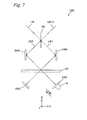
- Fig. 7 is a view showing an encoder 10E related to an application 1.
- Encoder 10E is configured including a beam splitter 35, reflection mirrors 22A and 22B placed so as to be opposed to each other below beam splitter 35, movable scale 24 placed below reflection mirrors 22A and 22B, reflection mirrors 22C and 22D placed below movable scale 24, actuator 16 that periodically oscillates reflection mirror 22D, and the like.
- illumination light LB that is obliquely incident on beam splitter 35 is branched into illumination light LB1 that propagates toward reflection mirror 22B and illumination light LB2 that propagates toward reflection mirror 22A, as shown in Fig. 7 .
- illumination lights LB1 and LB2 are deflected by reflection mirrors 22A and 22B respectively, and then are incident on movable scale 24 in a state of at least partly overlapping.
- Illumination lights LB1 and LB2 incident on movable scale 24 are transmitted through movable scale 24 and then are incident on reflection mirror 22C and reflection mirror 22D, respectively.
- Illumination light LB1 and illumination light LB2 incident on reflection mirrors 22C and 22D, respectively, are reflected off reflection mirrors 22C and 22D, and thereby are obliquely incident on beam splitter 35 via movable scale 24 and reflections mirrors 22A and 22B, in the order reverse to the previously described order. Then, illumination light LB1 is reflected off the surface on the +X side of beam splitter 35 and illumination light LB2 is transmitted through beam splitter 35, and thereby illumination light LB1 and illumination light LB2 are synthesized and received, as interference light LB12, by a photodetection element that is not illustrated.
- reflection mirror 22D that reflects illumination light LB2 that has been transmitted through movable scale 24 is periodically oscillated, by actuator 16, parallel to the incidence direction of illumination light LB2. Accordingly, the optical path length of illumination light LB2 periodically changes, and the periodic optical path difference occurs between the optical path of illumination light LB1 and the optical path of illumination light LB2. Therefore, encoder 10E can detect positional information of movable scale 24, similarly to encoder 10.
- Fig. 8 is a view showing an encoder 10F related to an application 2.
- Encoder 10F is configured including beam splitter 35, movable scale 24 placed below beam splitter 35, reflection mirrors 22C and 22D placed below movable scale 24, actuator 16 that periodically oscillates reflection mirror 22D, and the like.
- illumination light LB obliquely incident on beam splitter 35 is branched into illumination light LB1 and illumination light LB2, as shown in Fig. 8 . Then, illumination light LB1 and illumination light LB2 are incident on two different points on movable scale 24, respectively, and are diffracted at movable scale 24 and then are incident on reflection mirrors 22C and 22D, respectively.
- Illumination light LB1 and illumination light LB2 incident on reflection mirrors 22C and 22D, respectively, are reflected off reflection mirrors 22C and 22D, and are obliquely incident on beam splitter 35 via movable scale 24, in the order reverse to the previously described order. Then, illumination light LB1 is reflected off the surface on the +X side of beam splitter 35 and illumination light LB2 is transmitted through beam splitter 35, and thereby illumination light LB1 and illumination light LB2 are synthesized and received, as interference light LB12, by a photodetection element that is not illustrated.
- reflection mirror 22D that reflects illumination light LB2 that has been transmitted through movable scale 24 is periodically oscillated, by actuator 16, parallel to the incidence direction of illumination light LB2, and thereby the optical path length of illumination light LB2 periodically changes. Accordingly, the periodic optical path difference occurs between the optical path of illumination light LB1 and the optical path of illumination light LB2. Therefore, encoder 10F can detect positional information of movable scale 24, similarly to encoder 10.
- the present invention is not limited thereto, and the present invention can also be employed in the case where the section other than movable scale 24 moves together with the movable body.
- a configuration can be employed in which movable scale 24 and another optical member or the illumination light relatively move.
- index scale 20 and movable scale 24 each have the phase grating.
- the present invention is not limited thereto, and index scale 20 and movable scale 24 can each have a diffraction grating of an amplitude type (a diffraction grating of a bright/dark type), or one of index scale 20 and movable scale 24 can have the diffraction grating of an amplitude type and the other can have the phase grating.
- the ⁇ first order diffraction lights are used as the measurement lights.
- the present invention is not limited thereto, and the interference light of the higher order diffraction lights can be used as the measurement light.
- the interference light of the different order diffraction lights such as the 0 order light and the n th order (or -n th order) diffraction light, or the +n th order diffraction light and the +(m+n) th order diffraction light can also be used as the measurement lights.
- encoder 10 is a liner encoder that detects positional information of the movable body in the one axial direction.
- the present invention is not limited thereto, but can also be applied to a rotary encoder that detects the rotation amount of a rotatable body.
- the encoder of the present invention is suitable for optically detecting positional information of a movable body.
Landscapes
- Physics & Mathematics (AREA)
- General Physics & Mathematics (AREA)
- Optics & Photonics (AREA)
- Optical Transform (AREA)
- Facsimile Scanning Arrangements (AREA)
Abstract
Description
- The present invention relates to encoders, and more particularly to an encoder that optically detects positional information of a movable body.
- As an encoder by a scan method, an encoder has been proposed that irradiates an illumination light, which is modulated based on a predetermined modulation signal, on a scale that moves with a movable body and has a grating periodically formed along a movement direction, and compares a reflected light or a transmitted light of the illumination light with the modulation signal, thereby detecting positional information of the scale (e.g. refer to Patent Literature 1).
- In the encoder by a scan method, since the incidence position of the illumination light with respect to the scale needs to be periodically changed, for example, an oscillating mirror (a scanner) or the like used to oscillate the illumination light in a direction orthogonal to its propagation direction needs to be placed in an optical path of the illumination light. Therefore, in this type of the encoder, a space used to install the oscillating mirror or the like becomes necessary, which causes the inconvenience such as the increase in size and cost of an apparatus.
- Patent Literature 1:
U.S. Patent No. 6,639,696 - According to the present invention, there is provided an encoder that detects positional information of a movable body, making use of interference of a first illumination light and a second illumination light, the encoder comprising: a scale that has a pattern arrayed in a movement direction of the movable body, and moves relative to the first illumination light and the second illumination light according to movement of the movable body; an optical system that irradiates the first illumination light and the second illumination light on the pattern of the scale; and a modulator that periodically changes at least one of an optical path length of the first illumination light and an optical path length of the second illumination light.
- With this encoder, the optical path length of at least one of the first illumination light and the second illumination light is periodically changed by the modulator. Accordingly, an oscillating mirror, a scanner or the like that scans one of the first illumination light and the second illumination light with respect to the scale does not have to be arranged, and therefore it becomes possible to decrease the size and cost of an apparatus.
-
-
Fig. 1 is a view schematically showing a configuration of anencoder 10 related to an embodiment of the present invention. -
Fig. 2 is a view showing a schematic configuration of anencoder 10A. -
Fig. 3 is a view showing a schematic configuration of anencoder 10B. -
Figs. 4A and 4B are views used to explain an operation of aglass member 32A. -
Fig. 5 is a view showing a schematic configuration of anencoder 10C. -
Fig. 6 is a view showing a schematic configuration of anencoder 10D. -
Fig. 7 is a view showing a schematic configuration of anencoder 10E. -
Fig. 8 is a view showing a schematic configuration of anencoder 10F. - An embodiment of the present invention is described below, with reference to
Fig. 1 . -
Fig. 1 shows a schematic configuration of anencoder 10 related to an embodiment of the present invention. As shown inFig. 1 ,encoder 10 is an encoder by a so-called diffraction interference method and is a linear encoder that detects a movement direction, a movement distance, or displacement of a movable body that moves in an X-axis direction. - As shown in
Fig. 1 ,encoder 10 is equipped with alight source 12, anindex scale 20, a pair ofreflection mirrors actuator 16, amovable scale 24, aphotodetection element 26 and acontrol circuit 30. -
Light source 12 emits a coherent light, for example, an illumination light LB with a wavelength λ (= 850 nm) downward (toward a -Z direction) inFig. 1 . -
Index scale 20 is placed belowlight source 12.Index scale 20 is a transmissive phase grating on which a diffraction grating whose periodic direction is in the X-axis direction is formed. And, when illumination light LB emitted fromlight source 12 is incident onindex scale 20,index scale 20 generates a plurality of diffraction lights. InFig. 1 , of those diffraction lights, the ±first-order diffraction lights generated atindex scale 20 are shown. In the description below, the +first-order diffraction light outgoing toward the +X side is referred to as an illumination light LB1 and the -first-order diffraction light outgoing toward the -X side is referred to as an illumination light LB2. -
Reflection mirrors index scale 20 that are a predetermined distance apart in the -X direction and the +X direction from a vertical axis that passes through the center oflight source 12, in a state of being opposed to each other.Reflection mirrors index scale 20, and cause illumination lights LB1 and LB2 to be incident onmovable scale 24 in a state where illumination lights LB1 and LB2 at least partly overlap with each other. -
Actuator 16 is made up of, for example, a piezo element, and has the -X side end that is fixed to the surface on the +X side ofreflection mirror 22B.Actuator 16 periodically oscillatesreflection mirror 22B in the X-axis direction based on a modulation signal V(t) supplied fromcontrol circuit 30. -
Movable scale 24 is placed belowreflection mirrors Movable scale 24 is a transmissive phase grating having a periodic direction in the X-axis direction, on which a diffraction grating whose spatial frequency is ω is formed. And, illumination light LB1 and illumination light LB2 generated atindex scale 20 undergo the ±first diffraction atmovable scale 24, thereby being incident onphotodetection element 26 in a state of interfering with each other. In the description below, illumination lights LB1 and LB2 that have been transmitted throughmovable scale 24 are referred to as an interference light LB12 as a whole. -
Photodetection element 26 is placed belowmovable scale 24. When interference light LB12 frommovable scale 24 is incident onphotodetection element 26,photodetection element 26 outputs a photoelectric conversion signal I(t) in accordance with the interference degree of interference light LB12. -
Control circuit 30 generates modulation signal V(t) as expressed in the following formula (1) and supplies it toactuator 16. Then,control circuit 30 outputs a signal X(t) that includes positional information ofmovable scale 24 based on photoelectric conversion signal I(t) output fromphotodetection element 26. In this case, "r" denotes a coefficient, "ωr" denotes an angular frequency, and "t" denotes a time.
- When modulation signal V (t) is supplied to
actuator 16,reflection mirror 22B oscillates with a frequency f (= ωr / 2π) in the X-axis direction. Accordingly, the optical path length of illumination light LB1, of illumination lights LB1 and LB2 generated atindex scale 20, is periodically changed, and as a consequence, illumination light LB1 is periodically modulated. Then, illumination light LB1 and illumination light LB2 are incident onmovable scale 24 in a state of at least partly overlapping. - On
movable scale 24, the interference fringe is formed by the interference between illumination light LB1 and illumination light LB2. Then, this interference fringe moves (oscillates) along the X-axis, in proportion to angular frequency ω of modulation signal V(t). As a consequence, photoelectric conversion signal I(t) that is obtained byphotodetection element 26 receiving interference light LB12 becomes equivalent to a signal that is obtained by modulating positional information ofmovable scale 24 with modulation signal V(t), and is expressed in the following formula (2). In this case, "A" denotes the amplitude of displacement of the interference fringe that moves on the movable scale, "x0" denotes an initial offset quantity, and "x" denotes a phase ofmovable scale 24 with respect toindex scale 20.
-
Control circuit 30 computes positional information and movement information ofmovable scale 24 by performing, for example, the processing described inU. S. Patent No. 6, 639, 696 , to photoelectric conversion signal I(t), and outputs the computed information as output signal X(t) ofencoder 10. - As is described above, in
encoder 10 related to the present embodiment,reflection mirror 22B is oscillated in the X-axis direction based on modulation signal V(t). Accordingly, the optical path length of illumination light LB1, of illumination light LB1 and illumination light LB2 generated atindex scale 20, periodically changes, and as a consequence, illumination light LB1 is periodically modulated. Therefore, an extra scanner that scans illumination light LB1 or illumination light LB2 with respect to the movable scale does not have to be arranged, which allows an apparatus to be reduced in size and cost. - Incidentally, in the present embodiment, while only
reflection mirror 22B is oscillated byactuator 16 in the X-axis direction, it is also possible, for example, that onlyreflection mirror 22A is oscillated. Or,reflection mirrors - Further, as the configuration of an encoder that changes the optical path length of illumination light LB1 or illumination light LB2, various configurations can be considered, besides the configuration of
encoder 10 as described above. In the description below, six examples are specifically explained. -
Fig. 2 is a view showing anencoder 10A related to a modified example 1.Encoder 10A is different fromencoder 10 in that asecond index scale 31 is placed belowindex scale 20, instead of reflection mirrors 22A and 22B. -
Second index scale 31 is placed so as to be capable of turning around an axis parallel to a Y-axis with the -X side end serving as the center. And, the attitude ofsecond index scale 31 periodically changes from the attitude indicated by a solid line to the attitude indicated by two-dot chain line as shown inFig. 2 , because the +X side end ofsecond index scale 31 is oscillated in the vertical direction by an actuator that is not illustrated. Accordingly, inencoder 10A, the optical path length of illumination light LB1 is periodically changed, and the periodic optical path difference occurs between the optical path of illumination light LB1 and the optical path of illumination light LB2. Consequently,encoder 10A can detect positional information ofmovable scale 24, similarly toencoder 10. - Incidentally, in this modified example, while
second index scale 31 is turned, this is not intended to be limiting, and it is also possible thatsecond index scale 31 is periodically curved by oscillating the +X side end ofsecond index scale 31, with the -X side end serving as the origin. -
Fig. 3 shows anencoder 10B related to a modified example 2.Encoder 10B is different fromencoder 10 in that aglass member 32A having a U-like shape is placed belowlight source 12, instead ofindex scale 20 and reflection mirrors 22A and 22B. -
Glass member 32A is a member with a U-like ZX sectional shape that is made up of three sections, which are a set of plate-shaped sections that are placed, with the X-axis direction serving as their longitudinal directions, so as to be opposed in the vertical direction, and a connecting section that connects the -X side ends of the respective plate-shaped sections. Further, of a set of the plate-shaped sections, the plate-shaped section located on the upper side is shaped so as to be thicker than the plate-shaped section located on the lower side, and on the +X side ends of the respective plate shaped sections, the upper end and the lower end ofactuator 16 that expands/contracts in the vertical direction are fixed. And, on the upper surface of the plate-shaped section on the upper side, a diffraction grating that diffracts illumination light LB and generates illumination light LB1 and illumination light LB2 is formed, similarly to theindex scale 20. Further, on the lower surface of the plate-shaped section on the lower side, a diffraction grating is formed that diffracts illumination light LB1 and illumination light LB2 and causes the illumination lights to be incident onmovable scale 24 in a state where the illumination lights at least partly overlap. - In
glass member 32A configured as described above, whenactuator 16 is periodically expanded/contracted based on modulation signal V(t), the lower side plate-shaped section having a low stiffness is elastically deformed into a sine wave shape, periodically, as shown inFigs. 4A and 4B . Accordingly, the optical path length of illumination light LB1 and the optical path length of illumination light LB2 periodically change and the periodic optical path difference occurs between the optical path of illumination light LB1 and the optical path of illumination light LB2. Accordingly,encoder 10B can detect positional information ofmovable scale 24, similarly toencoder 10. -
Fig. 5 is a view showing anencoder 10C related to a modified example 3.Encoder 10C is different fromencoder 10 in that aglass member 32B having a rectangular parallelepiped shape is placed belowlight source 12, instead ofindex scale 20 and reflection mirrors 22A and 22B. -
Glass member 32B is placed with the X-axis direction serving as its longitudinal direction, and on the upper surface ofglass member 32B, a diffraction grating that generates illumination light LB1 and illumination light LB2 is formed, similarly toindex scale 20. Further, on the lower surface ofglass member 32B, a diffraction grating is formed that diffracts illumination light LB1 and illumination light LB2 respectively and causes the illumination lights to be incident onmovable scale 24 in a state where the illumination lights at least partly overlap. The pressure in the +X direction is made to operate on the surface on the -X side ofglass member 32B, byactuator 16 that expands/contracts in the X-axis direction. - In
encoder 10C,actuator 16 is expanded/contracted based on modulation signal V(t) having a frequency equivalent to the eigenfrequency ofglass member 32B, and therebyglass member 32B elastically deforms (expands/contracts) in the X-axis direction periodically, and the refractive-index distribution insideglass member 32B periodically varies. Accordingly, the optical path lengths of illumination light LB1 and illumination light LB2 periodically change and the periodic optical path difference occurs between the optical path of illumination light LB1 and the optical path of illumination light LB2. Therefore,encoder 10C can detect positional information ofmovable scale 24, similarly toencoder 10. -
Fig. 6 is a view showing anencoder 10D related to a modified example 4.Encoder 10D is different fromencoder 10 in that aglass member 32B having a rectangular parallelepiped shape is placed belowlight source 12, instead ofindex scale 20 and reflection mirrors 22A and 22B. -
Glass member 32B is placed with X-axis direction serving as its longitudinal direction, and on the upper surface, a diffraction grating that generates illumination light LB1 and illumination light LB2 is formed, similarly toindex scale 20. Further, on the lower surface ofglass member 32B, a diffraction grating is formed that diffracts illumination light LB1 and illumination light LB2 and causes the illumination lights to be incident onmovable scale 24 in a state where the illumination lights at least partly overlap. - In
encoder 10D, the AC voltage having a frequency equivalent to modulation signal V(t) is applied on the upper surface and the lower surface ofglass member 32B, via avoltage source 40, and therebyglass member 32B elastically deforms owing to the direct piezoelectric effect, and the refractive-index distribution insideglass member 32B periodically varies. Therefore, the optical path lengths of illumination light LB1 and illumination light LB2 periodically change, and the periodic optical path difference occurs between the optical path of illumination light LB1 and the optical path of illumination light LB2. Therefore,encoder 10D can detect positional information ofmovable scale 24, similarly toencoder 10. - Incidentally, in
encoders - The present invention can also be applied to, for example, the encoder disclosed in Kokai (Japanese Unexamined Patent Application Publication) No.
60-098302 application 1 and an application 2 are disclosed in detail in Kokai (Japanese Unexamined Patent Application Publication) No.60-098302 -
Fig. 7 is a view showing anencoder 10E related to anapplication 1.Encoder 10E is configured including abeam splitter 35, reflection mirrors 22A and 22B placed so as to be opposed to each other belowbeam splitter 35,movable scale 24 placed below reflection mirrors 22A and 22B, reflection mirrors 22C and 22D placed belowmovable scale 24,actuator 16 that periodically oscillatesreflection mirror 22D, and the like. - In
encoder 10E configured as described above, illumination light LB that is obliquely incident onbeam splitter 35 is branched into illumination light LB1 that propagates towardreflection mirror 22B and illumination light LB2 that propagates towardreflection mirror 22A, as shown inFig. 7 . Then, illumination lights LB1 and LB2 are deflected by reflection mirrors 22A and 22B respectively, and then are incident onmovable scale 24 in a state of at least partly overlapping. Illumination lights LB1 and LB2 incident onmovable scale 24 are transmitted throughmovable scale 24 and then are incident onreflection mirror 22C andreflection mirror 22D, respectively. - Illumination light LB1 and illumination light LB2 incident on reflection mirrors 22C and 22D, respectively, are reflected off reflection mirrors 22C and 22D, and thereby are obliquely incident on
beam splitter 35 viamovable scale 24 and reflections mirrors 22A and 22B, in the order reverse to the previously described order. Then, illumination light LB1 is reflected off the surface on the +X side ofbeam splitter 35 and illumination light LB2 is transmitted throughbeam splitter 35, and thereby illumination light LB1 and illumination light LB2 are synthesized and received, as interference light LB12, by a photodetection element that is not illustrated. - In
encoder 10E,reflection mirror 22D that reflects illumination light LB2 that has been transmitted throughmovable scale 24 is periodically oscillated, byactuator 16, parallel to the incidence direction of illumination light LB2. Accordingly, the optical path length of illumination light LB2 periodically changes, and the periodic optical path difference occurs between the optical path of illumination light LB1 and the optical path of illumination light LB2. Therefore,encoder 10E can detect positional information ofmovable scale 24, similarly toencoder 10. -
Fig. 8 is a view showing anencoder 10F related to an application 2.Encoder 10F is configured includingbeam splitter 35,movable scale 24 placed belowbeam splitter 35, reflection mirrors 22C and 22D placed belowmovable scale 24,actuator 16 that periodically oscillatesreflection mirror 22D, and the like. - In
encoder 10F configured as described above, illumination light LB obliquely incident onbeam splitter 35 is branched into illumination light LB1 and illumination light LB2, as shown inFig. 8 . Then, illumination light LB1 and illumination light LB2 are incident on two different points onmovable scale 24, respectively, and are diffracted atmovable scale 24 and then are incident on reflection mirrors 22C and 22D, respectively. - Illumination light LB1 and illumination light LB2 incident on reflection mirrors 22C and 22D, respectively, are reflected off reflection mirrors 22C and 22D, and are obliquely incident on
beam splitter 35 viamovable scale 24, in the order reverse to the previously described order. Then, illumination light LB1 is reflected off the surface on the +X side ofbeam splitter 35 and illumination light LB2 is transmitted throughbeam splitter 35, and thereby illumination light LB1 and illumination light LB2 are synthesized and received, as interference light LB12, by a photodetection element that is not illustrated. - In
encoder 10F,reflection mirror 22D that reflects illumination light LB2 that has been transmitted throughmovable scale 24 is periodically oscillated, byactuator 16, parallel to the incidence direction of illumination light LB2, and thereby the optical path length of illumination light LB2 periodically changes. Accordingly, the periodic optical path difference occurs between the optical path of illumination light LB1 and the optical path of illumination light LB2. Therefore,encoder 10F can detect positional information ofmovable scale 24, similarly toencoder 10. - Further, in the embodiment, the modified examples and the applications, the case has been described where
movable scale 24 moves relative to the illumination light. However, the present invention is not limited thereto, and the present invention can also be employed in the case where the section other thanmovable scale 24 moves together with the movable body. The point is that a configuration can be employed in whichmovable scale 24 and another optical member or the illumination light relatively move. - Further, in the embodiment, the case has been described where
index scale 20 andmovable scale 24 each have the phase grating. However, the present invention is not limited thereto, andindex scale 20 andmovable scale 24 can each have a diffraction grating of an amplitude type (a diffraction grating of a bright/dark type), or one ofindex scale 20 andmovable scale 24 can have the diffraction grating of an amplitude type and the other can have the phase grating. - Further, in the embodiment, the ±first order diffraction lights are used as the measurement lights. However, the present invention is not limited thereto, and the interference light of the higher order diffraction lights can be used as the measurement light. And, the interference light of the different order diffraction lights such as the 0 order light and the nth order (or -nth order) diffraction light, or the +nth order diffraction light and the +(m+n)th order diffraction light can also be used as the measurement lights.
- Further, in the embodiment, the explanation has been given assuming that
encoder 10 is a liner encoder that detects positional information of the movable body in the one axial direction. However, the present invention is not limited thereto, but can also be applied to a rotary encoder that detects the rotation amount of a rotatable body. - As is described above, the encoder of the present invention is suitable for optically detecting positional information of a movable body.
Claims (7)
- An encoder that detects positional information of a movable body, making use of interference of a first illumination light and a second illumination light, the encoder comprising:a scale that has a pattern arrayed in a movement direction of the movable body, and moves relative to the first illumination light and the second illumination light according to movement of the movable body;an optical system that irradiates the first illumination light and the second illumination light on the pattern of the scale; anda modulator that periodically changes at least one of an optical path length of the first illumination light and an optical path length of the second illumination light.
- The encoder according to claim 1, wherein
the modulator periodically changes at least one of the optical path length of the first illumination light and the optical path length of the second illumination light by periodically oscillating a position of an optical element included in the optical system. - The encoder according to claim 1, wherein
the optical system includes an optical element that is placed in an optical path of the first illumination light or the second illumination light and transmits the first illumination light and the second illumination light, and
the modulator periodically changes at least one of the optical path length of the first illumination light and the optical path length of the second illumination light by periodically varying a refractive index of the optical element. - The encoder according to one of claims 1 and 3, wherein
the optical system includes an optical element that is placed in an optical path of the first illumination light or the second illumination light and transmits the first illumination light and the second illumination light, and
the modulator periodically changes at least one of the optical path length of the first illumination light and the optical path length of the second illumination light by elastically deforming the optical element. - The encoder according to claim 4, wherein
the modulator elastically deforms the optical element in a mechanical manner. - The encoder according to claim 4, wherein
the modulator elastically deforms the optical element by applying an AC voltage on the optical element. - The encoder according to any one of claims 1 to 6, wherein
the scale is arranged on the movable body.
Applications Claiming Priority (2)
| Application Number | Priority Date | Filing Date | Title |
|---|---|---|---|
| JP2007261541 | 2007-10-05 | ||
| PCT/JP2008/002755 WO2009044542A1 (en) | 2007-10-05 | 2008-10-01 | Encoder |
Publications (2)
| Publication Number | Publication Date |
|---|---|
| EP2202492A1 true EP2202492A1 (en) | 2010-06-30 |
| EP2202492A4 EP2202492A4 (en) | 2014-12-31 |
Family
ID=40525974
Family Applications (1)
| Application Number | Title | Priority Date | Filing Date |
|---|---|---|---|
| EP08836628.1A Withdrawn EP2202492A4 (en) | 2007-10-05 | 2008-10-01 | Encoder |
Country Status (5)
| Country | Link |
|---|---|
| US (1) | US8222594B2 (en) |
| EP (1) | EP2202492A4 (en) |
| JP (1) | JP5212840B2 (en) |
| TW (1) | TWI463115B (en) |
| WO (1) | WO2009044542A1 (en) |
Families Citing this family (6)
| Publication number | Priority date | Publication date | Assignee | Title |
|---|---|---|---|---|
| NL2005259A (en) | 2009-09-29 | 2011-03-30 | Asml Netherlands Bv | Imprint lithography. |
| JP6199596B2 (en) * | 2012-12-17 | 2017-09-20 | 株式会社ミツトヨ | Illumination unit for optical encoder |
| DE102013203713A1 (en) * | 2013-03-05 | 2014-02-13 | Carl Zeiss Smt Gmbh | Incremental encoder for use in lithography device for detecting displacements or movements of optical elements, has lower movable reference grid and upper movable reference grid that include different lattice constants in optical path |
| NL2015639A (en) * | 2014-11-28 | 2016-09-20 | Asml Netherlands Bv | Encoder, position measurement system and lithographic apparatus. |
| US10546078B2 (en) | 2017-01-13 | 2020-01-28 | General Electric Company | Turbofan case for controlling blade deflection |
| WO2024134156A1 (en) * | 2022-12-20 | 2024-06-27 | Renishaw Plc | Encoder apparatus |
Family Cites Families (13)
| Publication number | Priority date | Publication date | Assignee | Title |
|---|---|---|---|---|
| JPS6098302A (en) | 1983-11-04 | 1985-06-01 | Sony Magnescale Inc | Optical displacement measuring device |
| JPS61176907A (en) * | 1985-01-31 | 1986-08-08 | Canon Inc | Imaging device |
| DE4338680C1 (en) * | 1993-11-12 | 1995-03-23 | Heidenhain Gmbh Dr Johannes | Length-measuring or angle-measuring device |
| JP3513247B2 (en) * | 1994-07-11 | 2004-03-31 | キヤノン株式会社 | Frequency shifter and optical displacement measuring device using the same |
| JP4023923B2 (en) * | 1998-07-02 | 2007-12-19 | ソニーマニュファクチュアリングシステムズ株式会社 | Optical displacement measuring device |
| US6639686B1 (en) | 2000-04-13 | 2003-10-28 | Nanowave, Inc. | Method of and apparatus for real-time continual nanometer scale position measurement by beam probing as by laser beams and the like of atomic and other undulating surfaces such as gratings or the like relatively moving with respect to the probing beams |
| EP1396704B1 (en) * | 2002-08-07 | 2015-10-07 | Dr. Johannes Heidenhain GmbH | Interferential position measuring device |
| US7332709B2 (en) * | 2004-12-13 | 2008-02-19 | Nikon Corporation | Photoelectric encoder |
| JP4899455B2 (en) * | 2004-12-13 | 2012-03-21 | 株式会社ニコン | Photoelectric encoder |
| US7394546B2 (en) * | 2005-05-23 | 2008-07-01 | Southwest Sciences Incorporated | Method and apparatus for full phase interferometry |
| JP2007170938A (en) * | 2005-12-21 | 2007-07-05 | Sendai Nikon:Kk | Encoder |
| JP4924884B2 (en) * | 2006-05-19 | 2012-04-25 | 株式会社ニコン | Encoder |
| US7601947B2 (en) * | 2006-05-19 | 2009-10-13 | Nikon Corporation | Encoder that optically detects positional information of a scale |
-
2008
- 2008-10-01 EP EP08836628.1A patent/EP2202492A4/en not_active Withdrawn
- 2008-10-01 WO PCT/JP2008/002755 patent/WO2009044542A1/en not_active Ceased
- 2008-10-01 JP JP2009535974A patent/JP5212840B2/en not_active Expired - Fee Related
- 2008-10-03 TW TW097138025A patent/TWI463115B/en not_active IP Right Cessation
-
2010
- 2010-03-25 US US12/731,725 patent/US8222594B2/en not_active Expired - Fee Related
Also Published As
| Publication number | Publication date |
|---|---|
| WO2009044542A1 (en) | 2009-04-09 |
| US20100176282A1 (en) | 2010-07-15 |
| TWI463115B (en) | 2014-12-01 |
| US8222594B2 (en) | 2012-07-17 |
| JPWO2009044542A1 (en) | 2011-02-03 |
| JP5212840B2 (en) | 2013-06-19 |
| EP2202492A4 (en) | 2014-12-31 |
| TW200923330A (en) | 2009-06-01 |
Similar Documents
| Publication | Publication Date | Title |
|---|---|---|
| CN102197286B (en) | Encoder | |
| JP4924879B2 (en) | Encoder | |
| US8222594B2 (en) | Encoder that optically detects positional information of a movable body by changing a path length through periodic oscillation of an optical element | |
| US7723671B2 (en) | Positional information detecting device | |
| EP1953505A1 (en) | Encoder | |
| EP1865292A1 (en) | Encoder | |
| US7332709B2 (en) | Photoelectric encoder | |
| WO2010089824A1 (en) | Encoder | |
| US7876451B2 (en) | Position-measuring device with movable deflection device and grating and with stationary grating, light source, and detector | |
| WO2007138869A1 (en) | Encoder | |
| EP1826535B1 (en) | Photoelectric encoder | |
| JP4946362B2 (en) | Encoder | |
| JP5862672B2 (en) | Encoder device and device | |
| JP2007303957A (en) | Encoder | |
| JP2007147283A (en) | Encoder |
Legal Events
| Date | Code | Title | Description |
|---|---|---|---|
| PUAI | Public reference made under article 153(3) epc to a published international application that has entered the european phase |
Free format text: ORIGINAL CODE: 0009012 |
|
| 17P | Request for examination filed |
Effective date: 20100408 |
|
| AK | Designated contracting states |
Kind code of ref document: A1 Designated state(s): AT BE BG CH CY CZ DE DK EE ES FI FR GB GR HR HU IE IS IT LI LT LU LV MC MT NL NO PL PT RO SE SI SK TR |
|
| AX | Request for extension of the european patent |
Extension state: AL BA MK RS |
|
| RAP1 | Party data changed (applicant data changed or rights of an application transferred) |
Owner name: NIKON CORPORATION |
|
| DAX | Request for extension of the european patent (deleted) | ||
| A4 | Supplementary search report drawn up and despatched |
Effective date: 20141202 |
|
| RIC1 | Information provided on ipc code assigned before grant |
Ipc: G01D 5/38 20060101AFI20141126BHEP Ipc: G02B 3/12 20060101ALI20141126BHEP Ipc: G02B 26/08 20060101ALI20141126BHEP Ipc: G02B 1/00 20060101ALI20141126BHEP |
|
| RAP1 | Party data changed (applicant data changed or rights of an application transferred) |
Owner name: NIKON CORPORATION |
|
| STAA | Information on the status of an ep patent application or granted ep patent |
Free format text: STATUS: THE APPLICATION IS DEEMED TO BE WITHDRAWN |
|
| 18D | Application deemed to be withdrawn |
Effective date: 20150630 |