EP2202433A2 - Dust seal structure of internal mixer - Google Patents
Dust seal structure of internal mixer Download PDFInfo
- Publication number
- EP2202433A2 EP2202433A2 EP09174872A EP09174872A EP2202433A2 EP 2202433 A2 EP2202433 A2 EP 2202433A2 EP 09174872 A EP09174872 A EP 09174872A EP 09174872 A EP09174872 A EP 09174872A EP 2202433 A2 EP2202433 A2 EP 2202433A2
- Authority
- EP
- European Patent Office
- Prior art keywords
- cylinder
- sealing member
- rotor shaft
- seal structure
- dust seal
- Prior art date
- Legal status (The legal status is an assumption and is not a legal conclusion. Google has not performed a legal analysis and makes no representation as to the accuracy of the status listed.)
- Granted
Links
- 239000000428 dust Substances 0.000 title claims abstract description 33
- 238000007789 sealing Methods 0.000 claims abstract description 83
- 239000000463 material Substances 0.000 claims abstract description 23
- 230000002093 peripheral effect Effects 0.000 claims abstract description 19
- 238000004898 kneading Methods 0.000 claims abstract description 16
- 239000000725 suspension Substances 0.000 claims description 4
- 239000012530 fluid Substances 0.000 description 6
- 150000001875 compounds Chemical class 0.000 description 3
- 238000012423 maintenance Methods 0.000 description 3
- 238000012986 modification Methods 0.000 description 3
- 230000004048 modification Effects 0.000 description 3
- 230000000694 effects Effects 0.000 description 2
- 239000010687 lubricating oil Substances 0.000 description 2
- 239000004033 plastic Substances 0.000 description 2
- 239000000654 additive Substances 0.000 description 1
- 230000000996 additive effect Effects 0.000 description 1
- 230000005540 biological transmission Effects 0.000 description 1
- 239000011248 coating agent Substances 0.000 description 1
- 238000000576 coating method Methods 0.000 description 1
- 239000000356 contaminant Substances 0.000 description 1
- 238000007599 discharging Methods 0.000 description 1
- 230000002708 enhancing effect Effects 0.000 description 1
- 238000009472 formulation Methods 0.000 description 1
- 239000000203 mixture Substances 0.000 description 1
- 238000012856 packing Methods 0.000 description 1
- 239000007858 starting material Substances 0.000 description 1
- 239000000126 substance Substances 0.000 description 1
Images


Classifications
-
- B—PERFORMING OPERATIONS; TRANSPORTING
- B01—PHYSICAL OR CHEMICAL PROCESSES OR APPARATUS IN GENERAL
- B01F—MIXING, e.g. DISSOLVING, EMULSIFYING OR DISPERSING
- B01F27/00—Mixers with rotary stirring devices in fixed receptacles; Kneaders
- B01F27/60—Mixers with rotary stirring devices in fixed receptacles; Kneaders with stirrers rotating about a horizontal or inclined axis
- B01F27/72—Mixers with rotary stirring devices in fixed receptacles; Kneaders with stirrers rotating about a horizontal or inclined axis with helices or sections of helices
-
- F—MECHANICAL ENGINEERING; LIGHTING; HEATING; WEAPONS; BLASTING
- F16—ENGINEERING ELEMENTS AND UNITS; GENERAL MEASURES FOR PRODUCING AND MAINTAINING EFFECTIVE FUNCTIONING OF MACHINES OR INSTALLATIONS; THERMAL INSULATION IN GENERAL
- F16J—PISTONS; CYLINDERS; SEALINGS
- F16J15/00—Sealings
- F16J15/16—Sealings between relatively-moving surfaces
- F16J15/34—Sealings between relatively-moving surfaces with slip-ring pressed against a more or less radial face on one member
- F16J15/3436—Pressing means
- F16J15/3448—Pressing means the pressing force resulting from fluid pressure
-
- B—PERFORMING OPERATIONS; TRANSPORTING
- B01—PHYSICAL OR CHEMICAL PROCESSES OR APPARATUS IN GENERAL
- B01F—MIXING, e.g. DISSOLVING, EMULSIFYING OR DISPERSING
- B01F35/00—Accessories for mixers; Auxiliary operations or auxiliary devices; Parts or details of general application
- B01F35/71—Feed mechanisms
-
- B—PERFORMING OPERATIONS; TRANSPORTING
- B29—WORKING OF PLASTICS; WORKING OF SUBSTANCES IN A PLASTIC STATE IN GENERAL
- B29B—PREPARATION OR PRETREATMENT OF THE MATERIAL TO BE SHAPED; MAKING GRANULES OR PREFORMS; RECOVERY OF PLASTICS OR OTHER CONSTITUENTS OF WASTE MATERIAL CONTAINING PLASTICS
- B29B7/00—Mixing; Kneading
- B29B7/02—Mixing; Kneading non-continuous, with mechanical mixing or kneading devices, i.e. batch type
- B29B7/22—Component parts, details or accessories; Auxiliary operations
-
- B—PERFORMING OPERATIONS; TRANSPORTING
- B29—WORKING OF PLASTICS; WORKING OF SUBSTANCES IN A PLASTIC STATE IN GENERAL
- B29B—PREPARATION OR PRETREATMENT OF THE MATERIAL TO BE SHAPED; MAKING GRANULES OR PREFORMS; RECOVERY OF PLASTICS OR OTHER CONSTITUENTS OF WASTE MATERIAL CONTAINING PLASTICS
- B29B7/00—Mixing; Kneading
- B29B7/02—Mixing; Kneading non-continuous, with mechanical mixing or kneading devices, i.e. batch type
- B29B7/22—Component parts, details or accessories; Auxiliary operations
- B29B7/24—Component parts, details or accessories; Auxiliary operations for feeding
- B29B7/246—Component parts, details or accessories; Auxiliary operations for feeding in mixers having more than one rotor and a casing closely surrounding the rotors, e.g. with feeding plungers
-
- F—MECHANICAL ENGINEERING; LIGHTING; HEATING; WEAPONS; BLASTING
- F16—ENGINEERING ELEMENTS AND UNITS; GENERAL MEASURES FOR PRODUCING AND MAINTAINING EFFECTIVE FUNCTIONING OF MACHINES OR INSTALLATIONS; THERMAL INSULATION IN GENERAL
- F16J—PISTONS; CYLINDERS; SEALINGS
- F16J15/00—Sealings
- F16J15/16—Sealings between relatively-moving surfaces
- F16J15/34—Sealings between relatively-moving surfaces with slip-ring pressed against a more or less radial face on one member
- F16J15/3436—Pressing means
-
- F—MECHANICAL ENGINEERING; LIGHTING; HEATING; WEAPONS; BLASTING
- F16—ENGINEERING ELEMENTS AND UNITS; GENERAL MEASURES FOR PRODUCING AND MAINTAINING EFFECTIVE FUNCTIONING OF MACHINES OR INSTALLATIONS; THERMAL INSULATION IN GENERAL
- F16J—PISTONS; CYLINDERS; SEALINGS
- F16J15/00—Sealings
- F16J15/16—Sealings between relatively-moving surfaces
- F16J15/34—Sealings between relatively-moving surfaces with slip-ring pressed against a more or less radial face on one member
- F16J15/3464—Mounting of the seal
- F16J15/3488—Split-rings
-
- F—MECHANICAL ENGINEERING; LIGHTING; HEATING; WEAPONS; BLASTING
- F16—ENGINEERING ELEMENTS AND UNITS; GENERAL MEASURES FOR PRODUCING AND MAINTAINING EFFECTIVE FUNCTIONING OF MACHINES OR INSTALLATIONS; THERMAL INSULATION IN GENERAL
- F16J—PISTONS; CYLINDERS; SEALINGS
- F16J15/00—Sealings
- F16J15/46—Sealings with packing ring expanded or pressed into place by fluid pressure, e.g. inflatable packings
-
- B—PERFORMING OPERATIONS; TRANSPORTING
- B29—WORKING OF PLASTICS; WORKING OF SUBSTANCES IN A PLASTIC STATE IN GENERAL
- B29B—PREPARATION OR PRETREATMENT OF THE MATERIAL TO BE SHAPED; MAKING GRANULES OR PREFORMS; RECOVERY OF PLASTICS OR OTHER CONSTITUENTS OF WASTE MATERIAL CONTAINING PLASTICS
- B29B7/00—Mixing; Kneading
- B29B7/02—Mixing; Kneading non-continuous, with mechanical mixing or kneading devices, i.e. batch type
- B29B7/06—Mixing; Kneading non-continuous, with mechanical mixing or kneading devices, i.e. batch type with movable mixing or kneading devices
- B29B7/10—Mixing; Kneading non-continuous, with mechanical mixing or kneading devices, i.e. batch type with movable mixing or kneading devices rotary
- B29B7/18—Mixing; Kneading non-continuous, with mechanical mixing or kneading devices, i.e. batch type with movable mixing or kneading devices rotary with more than one shaft
- B29B7/183—Mixing; Kneading non-continuous, with mechanical mixing or kneading devices, i.e. batch type with movable mixing or kneading devices rotary with more than one shaft having a casing closely surrounding the rotors, e.g. of Banbury type
-
- B—PERFORMING OPERATIONS; TRANSPORTING
- B29—WORKING OF PLASTICS; WORKING OF SUBSTANCES IN A PLASTIC STATE IN GENERAL
- B29B—PREPARATION OR PRETREATMENT OF THE MATERIAL TO BE SHAPED; MAKING GRANULES OR PREFORMS; RECOVERY OF PLASTICS OR OTHER CONSTITUENTS OF WASTE MATERIAL CONTAINING PLASTICS
- B29B7/00—Mixing; Kneading
- B29B7/74—Mixing; Kneading using other mixers or combinations of mixers, e.g. of dissimilar mixers ; Plant
- B29B7/7476—Systems, i.e. flow charts or diagrams; Plants
- B29B7/7495—Systems, i.e. flow charts or diagrams; Plants for mixing rubber
Definitions
- the present invention relates to a dust seal structure of an internal mixer for preventing the leakage of a material being kneaded.
- a batch type internal mixer is usually designed to produce a batch of compound by a series of actions comprising feeding materials of various formulations, such as rubber or plastic, into a mixing chamber by a floating weight, then kneading the material by the mixing rotors provided in the chamber and discharging the compound from the mixing chamber to the outside via a drop door after designated mixing action.
- the rotor shaft of the rotor is disposed to penetrate the mixing chamber.
- a leakage preventing means on the rotor shaft and the end surface of the rotor so that the contents of the mixing chamber does not leak from an end portion of the chamber to the outside.
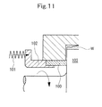
- a ring-shaped dust seal 100 has always been pressed against the end surface of a rotor 103 by the spring force of a spring 101 via a press fitting 102, thereby preventing a material being kneaded (may hereinafter be referred to as a kneading material (W)) within a mixing chamber from leaking to the outside (see Patent Document 1).
- a material being kneaded may hereinafter be referred to as a kneading material (W)) within a mixing chamber from leaking to the outside
- Patent Document1 JP-A-2002-18263 .
- Patent Document 2 Japanese Patent No. 3620944 .
- the present invention provides a dust seal structure of an internal mixer as defined in claim 1.
- the dust seal structure of an internal mixer includes a casing having a mixing chamber defined therein, and a rotor rotating in the mixing chamber for kneading a material, which is a material charged into the mixing chamber to be kneaded there, the dust seal structure comprising a ring-shaped cylinder fitted to a rotor shaft of the rotor and mounted on a peripheral edge of an opening portion of the casing through which the rotor shaft passes, the cylinder being located at the peripheral edge of the opening portion of the casing, and being adapted to urge a ring-shaped sealing member fitted on the rotor shaft in a direction of the rotor shaft to inhibit leakage of the kneading material from the mixing chamber.
- the sealing member may have sealing surfaces making close contact with and internally fitted on a peripheral surface of the opening portion of the casing and abutting on an end surface of the rotor.
- the sealing member may be urged by the cylinder via a ring-shaped press fitting movable within the opening portion of the casing in the direction of the rotor shaft.
- the sealing member may comprise a rotating sealing member fixedly provided on the rotor shaft and having a sealing surface on a side opposing an end surface of the rotor, and a fixed sealing member connected to the cylinder and urged toward a shaft end of the rotor shaft, and having a sealing surface in contact with the sealing surface of the rotating sealing member, and a tubular portion in sliding contact with a peripheral surface of the opening portion of the casing, and the sealing member may seal a gap between an outer peripheral surface side of the rotor shaft and an inner peripheral surface of the tubular portion.
- the rotating sealing member may be fixedly provided on a sleeve which is inserted into the tubular portion of the fixed sealing member and fitted on the rotor shaft.
- the cylinder may be a hydraulic cylinder.
- the cylinder may be pneumatic suspension cylinder.
- the cylinder may be formed to be divisible into a plurality of segments in a circumferential direction of the rotor shaft, and may have piston portions accommodated in one or more cylinder chambers defined independently of each other in the segments.
- the ring-shaped sealing member is urged by the ring-shaped cylinder.
- the uniformity of sealing pressure in the circumferential direction of the sealing member is obtained, resulting in enhanced sealability.
- maintenance work is easy, because it involves only pressure control over the cylinder.
- the cylinder is formed to be divisible into a plurality of segments in the circumferential direction of the rotor shaft. This facilitates the mounting and replacement of the cylinder, further improving the maintainability.
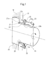
- Fig. 1 is a perspective sectional view of a dust seal structure showing Embodiment 1 of the present invention.
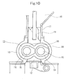
- Fig. 10 is a front sectional view of essential portions of an internal mixer.
- a casing 10 of an internal mixer, a floating weight 11, and a drop door 12 form a mixing chamber 13 having a cross section in the shape of spectacles.
- Two rotors 14 are disposed parallel to each other within the mixing chamber 13 , and are rotated in directions different from each other by drive devices (motors, power transmission gears, etc.; not shown) installed at the ends of their rotor shafts 15 .
- a blade portion 16 partially protruding in a radial direction is formed in the rotor 14, and the inner wall of the mixing chamber 13 has a curved surface corresponding to the locus of the blade portion 16 when rotated.
- a starting material such as rubber or plastic
- an additive such as a chemical
- the floating weight 11 is lowered to pressurize the kneading material.
- the rotors 14 are rotated, and the kneading material is engaged between the rotors 14, and kneaded in the mixing chamber.
- the compound is discharged to the outside by opening the drop door 12 in a lower part of the casing 10.
- a ring-shaped sealing member 21 split in two or the like in the circumferential direction is loosely fitted over the rotor shaft 15, with the sealing member 21 being located inside an opening portion 20 of the casing 10 which the rotor shafts 15 are inserted through.
- the sealing member 21 has a sealing surface 21a contacting the end surface of the rotor 14, and a sealing surface 21b contacting the circumferential surface of the opening portion 20 of the casing 10.
- the sealing member 21 is urged toward the end surface of the rotor 14 (in the direction of the rotor shaft) by a ring-shaped cylinder 23 mounted on the peripheral edge of the opening portion 2 0 of the casing 10 via a flanged tubular press fitting 22.
- the sealing member 21 has its sealing surface 21a brought into contact, under pressure, with the end surface of the rotor 14.
- the cylinder 23 is a hydraulic cylinder. Its head portion 24a is fixed to the outer wall surface of the casing 10 by a plurality of bolts 25 in the circumferential direction, and its piston portion 24b accommodated in a cylinder chamber of the head portion 24a and movable in the direction of the rotor shaft is connected to the flange part of the press fitting 22.
- Fig. 2 is a side sectional view of a dust seal structure showing Embodiment 2 of the present invention.
- Fig. 3 is a front view of a cylinder.
- Fig. 4A is a sectional view, taken along line A-A, in Fig. 3 .
- Fig. 4B is a sectional view, taken along line A-A, in Fig. 3 , in which a sealing member for a piston portion has been changed.
- Fig. 5 is a front view showing a modification of the cylinder.
- Embodiment 1 This is the dust seal structure of Embodiment 1 equipped with a ring-shaped rotating sealing member 27 which is fixedly provided on the rotor shaft 15 via a sleeve 26 and has a sealing surface 27a on a side opposing the end surface of the rotor 14, and a ring-shaped fixed sealing member 28 which is connected to a ring-shaped cylinder 23A, is urged in the shaft end direction of the rotor shaft 15, has a sealing surface 28a in contact with the sealing surface 27a of the rotating sealing member 27, and has a tubular portion 28b in sliding contact with the peripheral surface of the opening portion 20 of the casing 10 .
- the rotating sealing member 27 and the fixed sealing member 28 are preferably split in two in the circumferential direction.
- the cylinder 23A comprises a hydraulic cylinder.
- Piston portions 24b1, 24b2 thereof to be described later are fixed to the outer wall surface of the casing 10, and head portions 24a1, 24a2 thereof are connected to the fixed sealing member 28 in such a manner as to be movable in the rotor shaft direction under the pressure of hydraulic fluid supplied to the cylinder chamber.
- the head portions 24a1, 24a2 may be fixed, and the piston portions 24b1, 24b2 may be movable.
- the sealing surface 27a of the rotating sealing member 27 and the sealing surface 28a of the fixed sealing member 28 may be applied onto a base material by coating or overlaying for hardening, or may be applied by pasting a different member to a base material.
- a sealing member 29 acts between the peripheral surface of the opening portion 2 0 and the tubular portion 28b, and a key 33 works for the fixed sealing member 28.
- the cylinder 23A has its entire head portion formed to be divisible in two in the circumferential direction of the rotor shaft 15, as the head portions 24a1 and 24a2, and has the piston portions 24b1 and 24b2 accommodated in the cylinder chambers defined independently in these divisional head portions.
- the sealing members for the piston portions 24b1, 24b2, 0 rings 31a may be used (see Fig. 4A )
- packings 31b may be used (see Fig. 4B ).
- a plurality of oval or round cylinder chambers may be formed at equal intervals in the circumferential direction of the head portions 24a1, 24a2 provided in divisional form and assembled, and the piston portions 24b1, 24b2 may be accommodated therein. That is, when the head portions 24a1 and 24a2 are assembled in the shape of a ring, the piston portions 24b1 and 24b2 are arranged at equal intervals over the entire circumference.
- Other features are the same as those in Embodiment 1, and duplicate explanations are omitted.
- the head portions 24a1 and 24a2 assembled in the form of the ring are moved toward the shaft end of the rotor shaft 15 under the back pressure of the hydraulic fluid.
- the fixed sealing member 28 connected to the head portions 24a1, 24a2 is also urged in the same direction, and its sealing surface 28a is brought into contact under pressure with the sealing surface 27a of the rotating sealing member 27.
- the kneading material W is prevented from leaking from the aforementioned mixing chamber 13 to the outside by passing through a gap G1 between the end surface of the rotor 14 and the inner wall surface of the casing 10 and a gap G2 between the inner peripheral surface of the tubular portion 28b of the fixed sealing member 28 and the outer peripheral surface of the sleeve 26.
- the back pressure acts circumferentially evenly on the head portions 24al and 24a2 assembled in the form of the ring.
- a circumferentially uniform plunge pressure is exerted on the sealing surface 28a of the similarly ring-shaped fixed sealing member 28, thereby enhancing the sealability between the sealing surface 28a and the sealing surface 27a of the rotating sealing member 27.
- the cylinder 23A is formed to be divisible in two in the circumferential direction of the rotor shaft 15. This facilitates the mounting and replacement of the cylinder 23A, thus improving the maintainability further.
- the distance between the above-mentioned sealed region and the mixing chamber 13 is longer than that in Embodiment 1, thus suppressing the situation that the lubricating oil or the like supplied to the sealed region enters the kneading material W to deteriorate its quality.
- Fig. 6 is a side sectional view of a dust seal structure showing Embodiment 3 of the present invention.
- Fig. 7 is a front sectional view of a cylinder in this embodiment.
- Fig. 8 is a sectional view, taken along line B-B, in Fig. 7 .
- Fig. 9 is an explanation drawing of a piston portion.
- Embodiment 2 comprising the hydraulic cylinder is substituted by a cylinder 23B of a pneumatic suspension type using a rubber tube 30 or the like, the head portions 24a1, 24a2 are fixed to the outer wall surface of the casing 10 via a plurality of guides 32, and the piston portions 24b1, 24b2 of a channel section are connected to the fixed sealing member 28. Since other features are the same as those in Embodiment 2, duplicate explanations are omitted.
- the effects of preventing the entry of a contaminant (foreign matter in the lubricating oil) into the cylinder chamber, and leakage of the internal pressure of the cylinder are obtained by use of the cylinder 23B of the pneumatic suspension type, in addition to the same actions and effcts as those in Embodiment 2.
- the present invention is not limited to the above embodiments, and various changes and modifications may be made without departing from the gist of the present invention.
- the cylinder 23 of Embodiment 1 may be formed to be divisible into a plurality of segments in the circumferential direction of the rotor shaft 15.
- the cylinders 23A and 23B of Embodiments 2 and 3 may each be formed to be a ring-shaped integral member.
- the number of the divisional segments of the cylinders 23, 23A and 23B, if divided, need not be limited to two, but may be three or greater.
Landscapes
- Engineering & Computer Science (AREA)
- General Engineering & Computer Science (AREA)
- Mechanical Engineering (AREA)
- Physics & Mathematics (AREA)
- Fluid Mechanics (AREA)
- Architecture (AREA)
- Chemical & Material Sciences (AREA)
- Chemical Kinetics & Catalysis (AREA)
- Processing And Handling Of Plastics And Other Materials For Molding In General (AREA)
- Sealing Devices (AREA)
- Accessories For Mixers (AREA)
- Mixers Of The Rotary Stirring Type (AREA)
Abstract
Description
- The present invention relates to a dust seal structure of an internal mixer for preventing the leakage of a material being kneaded.
- A batch type internal mixer is usually designed to produce a batch of compound by a series of actions comprising feeding materials of various formulations, such as rubber or plastic, into a mixing chamber by a floating weight, then kneading the material by the mixing rotors provided in the chamber and discharging the compound from the mixing chamber to the outside via a drop door after designated mixing action.
- In such a mixer, the rotor shaft of the rotor is disposed to penetrate the mixing chamber. Thus, it is necessary to provide a leakage preventing means on the rotor shaft and the end surface of the rotor so that the contents of the mixing chamber does not leak from an end portion of the chamber to the outside.
- Hence, according to a conventional apparatus, as shown, for example, in
Fig. 11 , a ring-shaped dust seal 100 has always been pressed against the end surface of arotor 103 by the spring force of aspring 101 via apress fitting 102, thereby preventing a material being kneaded (may hereinafter be referred to as a kneading material (W)) within a mixing chamber from leaking to the outside (see Patent Document 1). - There is another conventional apparatus, as shown in
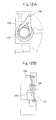
Figs. 12A and 12B , which has always pressed adust stop ring 104 against the end surface of arotor 107 by ahydraulic cylinder 106 via ayoke 105, thereby preventing a kneading material within a mixing chamber from leaking to the outside (see Patent Document 2). - Patent Document1:
JP-A-2002-18263 - Patent Document 2: Japanese Patent No.
3620944 - With the apparatus shown in
Fig. 11 , however, when the ring-shaped dust seal 100 has worn, there is need to maintain an appropriate sealing force by adjusting thesprings 101 provided at several locations in the circumferential direction. This has posed a problem about maintainability. With the apparatus shown inFigs. 12A and 12B , on the other hand, the hydraulic pressure of thehydraulic cylinder 106 is transmitted to two locations in the circumferential direction of thedust stop ring 104 via theyoke 105. Thus, the sealing force and/or pressure of thedust stop ring 104 becomes uneven in the circumferential direction, causing a problem about sealability. - It is an object of the present invention, therefore, to provide a dust seal structure of an internal mixer which affords a sealing pressure uniform in the circumferential direction, resulting in satisfactory sealability and excellent maintainability.
- To attain the aforementioned object, the present invention provides a dust seal structure of an internal mixer as defined in claim 1.
- The dust seal structure of an internal mixer according to the invention includes a casing having a mixing chamber defined therein, and a rotor rotating in the mixing chamber for kneading a material, which is a material charged into the mixing chamber to be kneaded there, the dust seal structure comprising a ring-shaped cylinder fitted to a rotor shaft of the rotor and mounted on a peripheral edge of an opening portion of the casing through which the rotor shaft passes, the cylinder being located at the peripheral edge of the opening portion of the casing, and being adapted to urge a ring-shaped sealing member fitted on the rotor shaft in a direction of the rotor shaft to inhibit leakage of the kneading material from the mixing chamber.
- The sealing member may have sealing surfaces making close contact with and internally fitted on a peripheral surface of the opening portion of the casing and abutting on an end surface of the rotor.
- The sealing member may be urged by the cylinder via a ring-shaped press fitting movable within the opening portion of the casing in the direction of the rotor shaft.
- The sealing member may comprise a rotating sealing member fixedly provided on the rotor shaft and having a sealing surface on a side opposing an end surface of the rotor, and a fixed sealing member connected to the cylinder and urged toward a shaft end of the rotor shaft, and having a sealing surface in contact with the sealing surface of the rotating sealing member, and a tubular portion in sliding contact with a peripheral surface of the opening portion of the casing, and the sealing member may seal a gap between an outer peripheral surface side of the rotor shaft and an inner peripheral surface of the tubular portion.
- The rotating sealing member may be fixedly provided on a sleeve which is inserted into the tubular portion of the fixed sealing member and fitted on the rotor shaft.
- The cylinder may be a hydraulic cylinder.
- The cylinder may be pneumatic suspension cylinder.
- The cylinder may be formed to be divisible into a plurality of segments in a circumferential direction of the rotor shaft, and may have piston portions accommodated in one or more cylinder chambers defined independently of each other in the segments.
- According to the above-described dust seal structure of an internal mixer concerned with the present invention, the ring-shaped sealing member is urged by the ring-shaped cylinder. Thus, the uniformity of sealing pressure in the circumferential direction of the sealing member is obtained, resulting in enhanced sealability. Moreover, maintenance work is easy, because it involves only pressure control over the cylinder. Furthermore, the cylinder is formed to be divisible into a plurality of segments in the circumferential direction of the rotor shaft. This facilitates the mounting and replacement of the cylinder, further improving the maintainability.
-
-
Fig. 1 is a perspective sectional view of a dust seal structure showing Embodiment 1 of the present invention. -
Fig. 2 is a side sectional view of a dust seal structure showing Embodiment 2 of the present invention. -
Fig. 3 is a front view of a cylinder. -
Fig. 4A is a sectional view, taken along line A-A, inFig. 3 . -
Fig. 4B is a sectional view, taken along line A-A, inFig. 3 , in which a sealing member for a piston portion has been changed. -
Fig. 5 is a front view of a modification of the cylinder. -
Fig. 6 is a side sectional view of a dust seal structure showing Embodiment 3 of the present invention. -
Fig. 7 is a front sectional view of a cylinder in Embodiment 3. -
Fig. 8 is a sectional view, taken along line B-B, inFig. 7 . -
Fig. 9 is an explanation drawing of the piston portion. -
Fig. 10 is a front sectional view of essential portions of an internal mixer. -
Fig. 11 is a side sectional view of a conventional dust seal structure. -
Fig. 12A is a front view of a conventional different dust seal structure. -
Fig. 12B is a side view of the conventional different dust seal structure. - Hereinafter, a dust seal structure of an internal mixer according to the present invention will be described in detail by embodiments with reference to the accompanying drawings.
-
Fig. 1 is a perspective sectional view of a dust seal structure showing Embodiment 1 of the present invention.Fig. 10 is a front sectional view of essential portions of an internal mixer. - As shown in
Fig. 10 , acasing 10 of an internal mixer, a floating weight 11, and adrop door 12 form amixing chamber 13 having a cross section in the shape of spectacles. - Two
rotors 14 are disposed parallel to each other within themixing chamber 13 , and are rotated in directions different from each other by drive devices (motors, power transmission gears, etc.; not shown) installed at the ends of theirrotor shafts 15 . Ablade portion 16 partially protruding in a radial direction is formed in therotor 14, and the inner wall of themixing chamber 13 has a curved surface corresponding to the locus of theblade portion 16 when rotated. - In the present mixer, a starting material such as rubber or plastic, and an additive such as a chemical (these materials will hereinafter be referred to collectively as a kneading material) are charged into the
mixing chamber 13 through aninlet 18 of ahopper 17, with an ascendable and descendable floating weight 11 being raised. Then, the floating weight 11 is lowered to pressurize the kneading material. In this state, therotors 14 are rotated, and the kneading material is engaged between therotors 14, and kneaded in the mixing chamber. Eventually, the compound is discharged to the outside by opening thedrop door 12 in a lower part of thecasing 10. - As shown in
Fig. 1 , a ring-shaped sealingmember 21 split in two or the like in the circumferential direction is loosely fitted over therotor shaft 15, with the sealingmember 21 being located inside an openingportion 20 of thecasing 10 which therotor shafts 15 are inserted through. The sealingmember 21 has a sealingsurface 21a contacting the end surface of therotor 14, and a sealingsurface 21b contacting the circumferential surface of the openingportion 20 of thecasing 10. - Moreover, the sealing
member 21 is urged toward the end surface of the rotor 14 (in the direction of the rotor shaft) by a ring-shapedcylinder 23 mounted on the peripheral edge of the opening portion 2 0 of thecasing 10 via a flangedtubular press fitting 22. Thus, the sealingmember 21 has itssealing surface 21a brought into contact, under pressure, with the end surface of therotor 14. - The
cylinder 23 is a hydraulic cylinder. Itshead portion 24a is fixed to the outer wall surface of thecasing 10 by a plurality ofbolts 25 in the circumferential direction, and itspiston portion 24b accommodated in a cylinder chamber of thehead portion 24a and movable in the direction of the rotor shaft is connected to the flange part of thepress fitting 22. - Because of the above configuration, when the hydraulic fluid or the like is supplied to the ring-shaped cylinder chamber, the similarly ring-shaped
piston portion 24b is moved toward the end surface of therotor 14 under its back pressure. Thus, the ring-shaped sealingmember 21 is urged toward the end surface of therotor 14 via the press fitting 22, and itssealing surface 21a is brought into contact, under pressure, with the end surface of therotor 14. Consequently, the kneading material W is prevented from leaking from theaforementioned mixing chamber 13 to the outside through the sealed region. - On this occasion, the back pressure acts on the ring-shaped
piston portion 24b evenly in the circumferential direction. On the sealingsurface 21a of the similarly ring-shaped sealingmember 21, therefore, a circumferentially uniform sealing pressure is obtained to improve the sealability. Furthermore, maintenance work is easy, because it involves only pressure control over the hydraulic fluid or the like which is supplied to the chamber of thecylinder 23. -
Fig. 2 is a side sectional view of a dust seal structure showing Embodiment 2 of the present invention.Fig. 3 is a front view of a cylinder.Fig. 4A is a sectional view, taken along line A-A, inFig. 3 .Fig. 4B is a sectional view, taken along line A-A, inFig. 3 , in which a sealing member for a piston portion has been changed.Fig. 5 is a front view showing a modification of the cylinder. - This is the dust seal structure of Embodiment 1 equipped with a ring-shaped rotating sealing
member 27 which is fixedly provided on therotor shaft 15 via asleeve 26 and has a sealingsurface 27a on a side opposing the end surface of therotor 14, and a ring-shaped fixed sealingmember 28 which is connected to a ring-shapedcylinder 23A, is urged in the shaft end direction of therotor shaft 15, has a sealingsurface 28a in contact with the sealingsurface 27a of the rotating sealingmember 27, and has atubular portion 28b in sliding contact with the peripheral surface of the openingportion 20 of thecasing 10 . The rotating sealingmember 27 and the fixed sealingmember 28 are preferably split in two in the circumferential direction. - In present embodiment, moreover, the
cylinder 23A comprises a hydraulic cylinder. Piston portions 24b1, 24b2 thereof to be described later are fixed to the outer wall surface of thecasing 10, and head portions 24a1, 24a2 thereof are connected to the fixed sealingmember 28 in such a manner as to be movable in the rotor shaft direction under the pressure of hydraulic fluid supplied to the cylinder chamber. As in Embodiment 1, the head portions 24a1, 24a2 may be fixed, and the piston portions 24b1, 24b2 may be movable. - The sealing
surface 27a of the rotating sealingmember 27 and the sealingsurface 28a of the fixed sealingmember 28 may be applied onto a base material by coating or overlaying for hardening, or may be applied by pasting a different member to a base material. InFig. 2 , a sealingmember 29 acts between the peripheral surface of the opening portion 2 0 and thetubular portion 28b, and a key 33 works for the fixed sealingmember 28. - As shown in
Fig. 3 andFigs. 4A, 4B , thecylinder 23A has its entire head portion formed to be divisible in two in the circumferential direction of therotor shaft 15, as the head portions 24a1 and 24a2, and has the piston portions 24b1 and 24b2 accommodated in the cylinder chambers defined independently in these divisional head portions. As the sealing members for the piston portions 24b1, 24b2, 0rings 31a may be used (seeFig. 4A ) , orpackings 31b may be used (seeFig. 4B ). - As shown in
Fig. 5 , moreover, a plurality of oval or round cylinder chambers may be formed at equal intervals in the circumferential direction of the head portions 24a1, 24a2 provided in divisional form and assembled, and the piston portions 24b1, 24b2 may be accommodated therein. That is, when the head portions 24a1 and 24a2 are assembled in the shape of a ring, the piston portions 24b1 and 24b2 are arranged at equal intervals over the entire circumference. Other features are the same as those in Embodiment 1, and duplicate explanations are omitted. - According to the present embodiment, therefore, when the hydraulic fluid or the like is supplied at the same pressure to each chamber of the
cylinder 23A, the head portions 24a1 and 24a2 assembled in the form of the ring are moved toward the shaft end of therotor shaft 15 under the back pressure of the hydraulic fluid. Thus, the fixed sealingmember 28 connected to the head portions 24a1, 24a2 is also urged in the same direction, and itssealing surface 28a is brought into contact under pressure with the sealingsurface 27a of the rotating sealingmember 27. - As a result, the kneading material W is prevented from leaking from the
aforementioned mixing chamber 13 to the outside by passing through a gap G1 between the end surface of therotor 14 and the inner wall surface of thecasing 10 and a gap G2 between the inner peripheral surface of thetubular portion 28b of the fixed sealingmember 28 and the outer peripheral surface of thesleeve 26. - On this occasion, the back pressure acts circumferentially evenly on the head portions 24al and 24a2 assembled in the form of the ring. Thus, a circumferentially uniform plunge pressure is exerted on the sealing
surface 28a of the similarly ring-shaped fixed sealingmember 28, thereby enhancing the sealability between the sealingsurface 28a and the sealingsurface 27a of the rotating sealingmember 27. - Moreover, maintenance work is easy, because it involves only pressure control over the hydraulic fluid or the like which is supplied to the chamber of the
cylinder 23A. Furthermore, thecylinder 23A is formed to be divisible in two in the circumferential direction of therotor shaft 15. This facilitates the mounting and replacement of thecylinder 23A, thus improving the maintainability further. In addition, the distance between the above-mentioned sealed region and the mixingchamber 13 is longer than that in Embodiment 1, thus suppressing the situation that the lubricating oil or the like supplied to the sealed region enters the kneading material W to deteriorate its quality. -
Fig. 6 is a side sectional view of a dust seal structure showing Embodiment 3 of the present invention.Fig. 7 is a front sectional view of a cylinder in this embodiment.Fig. 8 is a sectional view, taken along line B-B, inFig. 7 .Fig. 9 is an explanation drawing of a piston portion. - This is an embodiment in which the
cylinder 23A of Embodiment 2 comprising the hydraulic cylinder is substituted by acylinder 23B of a pneumatic suspension type using arubber tube 30 or the like, the head portions 24a1, 24a2 are fixed to the outer wall surface of thecasing 10 via a plurality ofguides 32, and the piston portions 24b1, 24b2 of a channel section are connected to the fixed sealingmember 28. Since other features are the same as those in Embodiment 2, duplicate explanations are omitted. - According to the present embodiment, the effects of preventing the entry of a contaminant (foreign matter in the lubricating oil) into the cylinder chamber, and leakage of the internal pressure of the cylinder are obtained by use of the
cylinder 23B of the pneumatic suspension type, in addition to the same actions and effcts as those in Embodiment 2. - It goes without saying that the present invention is not limited to the above embodiments, and various changes and modifications may be made without departing from the gist of the present invention. For example, the
cylinder 23 of Embodiment 1 may be formed to be divisible into a plurality of segments in the circumferential direction of therotor shaft 15. Alternatively, thecylinders cylinders -
- 10
- Casing
- 11
- Floating weight
- 12
- Drop door
- 13
- Mixing chamber
- 14
- Rotor
- 15
- Rotor shaft
- 21
- Sealing member
- 21a,21b
- Sealing surface
- 22
- Press fitting
- 23,23A,23B
- Cylinder
- 24a,24a1,24a2
- Head portion
- 24b,24b1,24b2
- Piston portion
- 26
- Sleeve
- 27
- Rotating sealing member
- 27a
- Sealing surface
- 28
- Fixed sealing member
- 28a
- Sealing surface
- 28b
- Tubular portion
- 30
- Rubber tube
- W
- Kneading material
Claims (8)
- A dust seal structure of an internal mixer including a casing (10) having a mixing chamber (13) defined therein, and a rotor (14) rotating in the mixing chamber for kneading a material (W), which is charged into the mixing chamber (13) to be kneaded there,the dust seal structure comprising a ring-shaped cylinder (23,23A,23B) fitted to a rotor shaft (15) of the rotor (14) and mounted on a peripheral edge of an opening portion (20) of the casing (10) through which the rotor shaft (15) passes,the cylinder (23,23A,23B) being located at the peripheral edge of the opening portion (20) of the casing (10), and being adapted to urge a ring-shaped sealing member (21) fitted on the rotor shaft (15) in a direction of the rotor shaft (15) to inhibit leakage of the kneading material from the mixing chamber (13).
- The dust seal structure of an internal mixer according to claim 1, whereinthe sealing member (21) has sealing surfaces (21a,21b) making close contact with and internally fitted on a peripheral surface of the opening portion (20) of the casing (10) and abutting on an end surface of the rotor (14).
- The dust seal structure of an internal mixer according to claim 2, whereinthe sealing member (21) is urged by the cylinder (23) via a ring-shaped press fitting (22) movable within the opening portion (20) of the casing (10) in the direction of the rotor shaft (15).
- The dust seal structure of an internal mixer according to claim 1, 2 or 3, whereinthe sealing member (21) comprisesa rotating sealing member (27) fixedly provided on the rotor shaft (15) and having a sealing surface (27a) on a side opposing an end surface of the rotor (14), anda fixed sealing member (28) connected to the cylinder (23A,23B) and urged toward a shaft end of the rotor shaft (15), and having a sealing surface (28a) in contact with the sealing surface (27a) of the rotating sealing member (27), and a tubular portion (28b) in sliding contact with a peripheral surface of the opening portion (20) of the casing (10), andthe sealing member (21) seals a gap between an outer peripheral surface side of the rotor shaft (15) and an inner peripheral surface of the tubular portion (28b).
- The dust seal structure of an internal mixer according to claim 4, whereinthe rotating sealing member (27) is fixedly provided on a sleeve (26) which is inserted into the tubular portion (28b) of the fixed sealing member (28) and fitted on the rotor shaft (15).
- The dust seal structure of an internal mixer according to any one of claims 1 to 5, whereinthe cylinder (23,23A) is a hydraulic cylinder.
- The dust seal structure of an internal mixer according to any one of claims 1 to 5, whereinthe cylinder (23B) is a pneumatic suspension cylinder.
- The dust seal structure of an internal mixer according to any one of claims 1 to 7, whereinthe cylinder (23A,23B) is formed to be divisible into a plurality of segments in a circumferential direction of the rotor shaft (15), andhas piston portions (24b1, 24b2) accommodated in one or more cylinder chambers defined independently of each other in the segments.
Applications Claiming Priority (1)
| Application Number | Priority Date | Filing Date | Title |
|---|---|---|---|
| JP2008327050A JP5173787B2 (en) | 2008-12-24 | 2008-12-24 | Dust seal structure of hermetic kneader |
Publications (3)
| Publication Number | Publication Date |
|---|---|
| EP2202433A2 true EP2202433A2 (en) | 2010-06-30 |
| EP2202433A3 EP2202433A3 (en) | 2011-10-05 |
| EP2202433B1 EP2202433B1 (en) | 2013-01-16 |
Family
ID=42062500
Family Applications (1)
| Application Number | Title | Priority Date | Filing Date |
|---|---|---|---|
| EP09174872A Not-in-force EP2202433B1 (en) | 2008-12-24 | 2009-11-03 | Dust seal structure of internal mixer |
Country Status (5)
| Country | Link |
|---|---|
| US (1) | US20100156051A1 (en) |
| EP (1) | EP2202433B1 (en) |
| JP (1) | JP5173787B2 (en) |
| KR (1) | KR101156343B1 (en) |
| CN (1) | CN101758566B (en) |
Cited By (2)
| Publication number | Priority date | Publication date | Assignee | Title |
|---|---|---|---|---|
| EP2810756A1 (en) * | 2009-01-13 | 2014-12-10 | Kabushiki Kaisha Kobe Seiko Sho | Internal batch mixer |
| WO2015066276A1 (en) * | 2013-10-31 | 2015-05-07 | General Electric Company | Seal having variable elastic modulus |
Families Citing this family (6)
| Publication number | Priority date | Publication date | Assignee | Title |
|---|---|---|---|---|
| JP5173787B2 (en) * | 2008-12-24 | 2013-04-03 | 三菱重工マシナリーテクノロジー株式会社 | Dust seal structure of hermetic kneader |
| CN102671575B (en) * | 2012-04-27 | 2013-12-25 | 大连华阳密封股份有限公司 | A locking device for stirring and sealing and its disassembling method |
| EP2662195B1 (en) * | 2012-05-07 | 2018-10-24 | Coperion GmbH | Multiple shaft extruder for performing an extrusion method and reactive extrusion method |
| KR101356761B1 (en) * | 2013-08-28 | 2014-02-03 | 구보현 | Sealing apparatus for rotor axis of dispersion kneader |
| US9880067B2 (en) * | 2013-12-03 | 2018-01-30 | Pall Corporation | Mechanical agitator with seal housing assembly |
| CN111970878B (en) * | 2020-09-09 | 2021-06-11 | 濮阳市立圆汽车电器有限公司 | Vehicle-mounted inverter with dustproof structure |
Citations (2)
| Publication number | Priority date | Publication date | Assignee | Title |
|---|---|---|---|---|
| JP2002018263A (en) | 2000-07-07 | 2002-01-22 | Mitsubishi Heavy Ind Ltd | Kneader |
| JP3620944B2 (en) | 1997-02-18 | 2005-02-16 | 株式会社神戸製鋼所 | Dust stop device for closed kneader |
Family Cites Families (31)
| Publication number | Priority date | Publication date | Assignee | Title |
|---|---|---|---|---|
| US2340022A (en) * | 1940-08-15 | 1944-01-25 | Read Machinery Co Inc | Shaft seal |
| US2863681A (en) * | 1955-10-04 | 1958-12-09 | Robbins Machine & Mfg Co Inc | Inflatable seal for rotating shafts |
| US3963247A (en) * | 1970-12-01 | 1976-06-15 | Stamicarbon B.V. | Shaft seal |
| US3949972A (en) * | 1975-07-02 | 1976-04-13 | Usm Corporation | Direct acting hydraulic dust stop |
| JPS5260781A (en) * | 1975-11-12 | 1977-05-19 | Honshu Paper Co Ltd | Constant pressure mechanism for sealing equipment |
| US4401306A (en) * | 1977-04-11 | 1983-08-30 | Arnold James F | Floating roof tank seal |
| JPS5835464Y2 (en) * | 1979-01-24 | 1983-08-10 | 株式会社神戸製鋼所 | Rotor shaft sealing device for synthetic resin kneading extruders, etc. |
| JPS5914250B2 (en) * | 1981-02-06 | 1984-04-03 | 正夫 森山 | Leakage prevention device for kneading machines, etc. |
| JPS59155361U (en) * | 1983-04-06 | 1984-10-18 | イ−グル工業株式会社 | Shaft seal |
| JPS6044031A (en) * | 1983-08-22 | 1985-03-08 | Masao Moriyama | Leak preventing apparatus for kneader or the like |
| JPH0230021Y2 (en) * | 1985-08-24 | 1990-08-13 | ||
| AU587640B2 (en) * | 1985-10-17 | 1989-08-24 | Flexibox Limited | A mechanical seal |
| JPS63297003A (en) * | 1987-05-29 | 1988-12-05 | Masao Moriyama | Kneader |
| DE3843288A1 (en) * | 1988-12-22 | 1990-06-28 | Dieter R Just | Slide-ring seal |
| JPH0688250B2 (en) * | 1989-04-10 | 1994-11-09 | 日本ロール製造株式会社 | Shaft sealing device for easy removal of invading powder from kneading machine |
| JPH0679156A (en) * | 1992-09-01 | 1994-03-22 | Kobe Steel Ltd | Sealing device of closed kneader |
| JPH0632010U (en) * | 1992-09-30 | 1994-04-26 | 株式会社神戸製鋼所 | Sealing device for closed kneader |
| JP2501547B2 (en) * | 1992-10-27 | 1996-05-29 | 株式会社神戸製鋼所 | Hydraulic controller for closed kneader |
| JPH09309109A (en) * | 1996-05-23 | 1997-12-02 | Mitsubishi Heavy Ind Ltd | Leakage prevention device for kneaded materials in rubber kneading machine |
| JPH1076150A (en) * | 1996-09-03 | 1998-03-24 | Mitsubishi Heavy Ind Ltd | Dust stop of pressure kneader |
| JPH10151333A (en) * | 1996-11-20 | 1998-06-09 | Kobe Steel Ltd | Dust stop device for internal mixer |
| DE19819741A1 (en) * | 1998-05-02 | 1999-11-04 | Krupp Kunststofftechnik Gmbh | Rotor shaft seal for industrial mixer for abrasive mixtures such as plastics |
| ES2207925T3 (en) * | 1998-07-10 | 2004-06-01 | Coperion Buss Ag | MIXING AND MIXING MACHINE. |
| JP4335418B2 (en) | 2000-07-06 | 2009-09-30 | 三菱重工業株式会社 | Kneading machine |
| US20020057626A1 (en) * | 2000-11-07 | 2002-05-16 | Schafer Harold L. | Upstream seal for mixer rotors |
| US6390666B1 (en) * | 2000-11-07 | 2002-05-21 | Tech, Process & Engineering, Inc. | Packing gland seal assembly as an upstream seal for mixer rotors |
| DE10161779A1 (en) * | 2001-12-18 | 2003-07-03 | Thyssenkrupp Elastomertechnik | internal mixer |
| JP2003269864A (en) * | 2002-03-14 | 2003-09-25 | Jfe Engineering Kk | Rotary kiln sealing device |
| US7121716B2 (en) * | 2004-03-30 | 2006-10-17 | Alliant Techsystems Inc. | Mixing equipment sealing device |
| JP5173787B2 (en) * | 2008-12-24 | 2013-04-03 | 三菱重工マシナリーテクノロジー株式会社 | Dust seal structure of hermetic kneader |
| JP5356045B2 (en) * | 2009-01-13 | 2013-12-04 | 株式会社神戸製鋼所 | Sealed kneader and method for monitoring the position of fixed side seal member of sealed kneader |
-
2008
- 2008-12-24 JP JP2008327050A patent/JP5173787B2/en not_active Expired - Fee Related
-
2009
- 2009-10-27 US US12/606,649 patent/US20100156051A1/en not_active Abandoned
- 2009-11-03 EP EP09174872A patent/EP2202433B1/en not_active Not-in-force
- 2009-12-22 CN CN2009102622709A patent/CN101758566B/en not_active Expired - Fee Related
- 2009-12-23 KR KR1020090129616A patent/KR101156343B1/en not_active Expired - Fee Related
Patent Citations (2)
| Publication number | Priority date | Publication date | Assignee | Title |
|---|---|---|---|---|
| JP3620944B2 (en) | 1997-02-18 | 2005-02-16 | 株式会社神戸製鋼所 | Dust stop device for closed kneader |
| JP2002018263A (en) | 2000-07-07 | 2002-01-22 | Mitsubishi Heavy Ind Ltd | Kneader |
Cited By (2)
| Publication number | Priority date | Publication date | Assignee | Title |
|---|---|---|---|---|
| EP2810756A1 (en) * | 2009-01-13 | 2014-12-10 | Kabushiki Kaisha Kobe Seiko Sho | Internal batch mixer |
| WO2015066276A1 (en) * | 2013-10-31 | 2015-05-07 | General Electric Company | Seal having variable elastic modulus |
Also Published As
| Publication number | Publication date |
|---|---|
| US20100156051A1 (en) | 2010-06-24 |
| JP5173787B2 (en) | 2013-04-03 |
| CN101758566A (en) | 2010-06-30 |
| KR20100075402A (en) | 2010-07-02 |
| KR101156343B1 (en) | 2012-06-13 |
| CN101758566B (en) | 2012-12-12 |
| EP2202433B1 (en) | 2013-01-16 |
| JP2010149292A (en) | 2010-07-08 |
| EP2202433A3 (en) | 2011-10-05 |
Similar Documents
| Publication | Publication Date | Title |
|---|---|---|
| EP2202433B1 (en) | Dust seal structure of internal mixer | |
| EP2891836B1 (en) | Mechanical seal device | |
| US11460100B2 (en) | Method for installing a transmission and shaftseat applied thereby | |
| EP1963622B1 (en) | Self-centering floating brush seal, corresponding assembly and retrofitting method | |
| US9004890B2 (en) | Gear wheel pump | |
| WO2018138981A1 (en) | Compression vulcanization molding mold for rolling bearing seal, and method for manufacturing rolling bearing seal | |
| CN104981637A (en) | Seal ring with frictional load surface | |
| US5171022A (en) | Shaft seal of a mixing and kneading machine | |
| CN108843615B (en) | Rotor pump shaft sealing device | |
| KR20140066732A (en) | Rolling stand roll neck seal | |
| US20100196186A1 (en) | Gear pump | |
| JP5548596B2 (en) | Shaft seal device for submersible pump | |
| CN1225597A (en) | direct drive coiler | |
| CN103097731A (en) | Gear pump | |
| CN201735365U (en) | Vacuum stone stirrer shaft-end sealing device | |
| US5409241A (en) | Positive drive compensating shaft seal | |
| CN214888865U (en) | Split type mechanical sealing device | |
| JPH10151333A (en) | Dust stop device for internal mixer | |
| JP5758705B2 (en) | Gear spindle and oil seal used therefor | |
| CN111212995A (en) | Sealing Rings and Sealing Structures | |
| IT201900020112A1 (en) | DYNAMIC INTERFERENCE SEALING DEVICE AND SYSTEM WITH IMPROVED CONTACT BEHAVIOR | |
| CN210178924U (en) | Shaft seal | |
| JPH09309109A (en) | Leakage prevention device for kneaded materials in rubber kneading machine | |
| JP4415600B2 (en) | Sealing structure with oil seal | |
| CN208487054U (en) | Pump more mechanical seal quick replacement devices |
Legal Events
| Date | Code | Title | Description |
|---|---|---|---|
| PUAI | Public reference made under article 153(3) epc to a published international application that has entered the european phase |
Free format text: ORIGINAL CODE: 0009012 |
|
| 17P | Request for examination filed |
Effective date: 20091103 |
|
| AK | Designated contracting states |
Kind code of ref document: A2 Designated state(s): AT BE BG CH CY CZ DE DK EE ES FI FR GB GR HR HU IE IS IT LI LT LU LV MC MK MT NL NO PL PT RO SE SI SK SM TR |
|
| AX | Request for extension of the european patent |
Extension state: AL BA RS |
|
| PUAL | Search report despatched |
Free format text: ORIGINAL CODE: 0009013 |
|
| AK | Designated contracting states |
Kind code of ref document: A3 Designated state(s): AT BE BG CH CY CZ DE DK EE ES FI FR GB GR HR HU IE IS IT LI LT LU LV MC MK MT NL NO PL PT RO SE SI SK SM TR |
|
| AX | Request for extension of the european patent |
Extension state: AL BA RS |
|
| RIC1 | Information provided on ipc code assigned before grant |
Ipc: B29B 7/20 20060101ALN20110829BHEP Ipc: F16J 15/16 20060101AFI20110829BHEP Ipc: F16J 15/46 20060101ALI20110829BHEP Ipc: F16J 15/34 20060101ALI20110829BHEP |
|
| GRAP | Despatch of communication of intention to grant a patent |
Free format text: ORIGINAL CODE: EPIDOSNIGR1 |
|
| RIC1 | Information provided on ipc code assigned before grant |
Ipc: B29B 7/20 20060101ALN20120515BHEP Ipc: B29B 7/18 20060101ALI20120515BHEP Ipc: F16J 15/16 20060101AFI20120515BHEP Ipc: F16J 15/34 20060101ALI20120515BHEP Ipc: F16J 15/46 20060101ALI20120515BHEP Ipc: B29B 7/24 20060101ALI20120515BHEP |
|
| GRAS | Grant fee paid |
Free format text: ORIGINAL CODE: EPIDOSNIGR3 |
|
| RIN1 | Information on inventor provided before grant (corrected) |
Inventor name: MORITA, MITSURU Inventor name: HANADA, SHUICHI Inventor name: NISHIHARA, YOSHIKAZU Inventor name: MORIBE, TAKASHI Inventor name: TATEMI, HIROKI |
|
| GRAA | (expected) grant |
Free format text: ORIGINAL CODE: 0009210 |
|
| AK | Designated contracting states |
Kind code of ref document: B1 Designated state(s): AT BE BG CH CY CZ DE DK EE ES FI FR GB GR HR HU IE IS IT LI LT LU LV MC MK MT NL NO PL PT RO SE SI SK SM TR |
|
| REG | Reference to a national code |
Ref country code: GB Ref legal event code: FG4D |
|
| REG | Reference to a national code |
Ref country code: CH Ref legal event code: EP |
|
| REG | Reference to a national code |
Ref country code: IE Ref legal event code: FG4D |
|
| REG | Reference to a national code |
Ref country code: AT Ref legal event code: REF Ref document number: 594078 Country of ref document: AT Kind code of ref document: T Effective date: 20130215 Ref country code: CH Ref legal event code: EP |
|
| REG | Reference to a national code |
Ref country code: DE Ref legal event code: R096 Ref document number: 602009012784 Country of ref document: DE Effective date: 20130321 |
|
| REG | Reference to a national code |
Ref country code: AT Ref legal event code: MK05 Ref document number: 594078 Country of ref document: AT Kind code of ref document: T Effective date: 20130116 |
|
| REG | Reference to a national code |
Ref country code: NL Ref legal event code: VDEP Effective date: 20130116 |
|
| REG | Reference to a national code |
Ref country code: LT Ref legal event code: MG4D |
|
| PG25 | Lapsed in a contracting state [announced via postgrant information from national office to epo] |
Ref country code: BG Free format text: LAPSE BECAUSE OF FAILURE TO SUBMIT A TRANSLATION OF THE DESCRIPTION OR TO PAY THE FEE WITHIN THE PRESCRIBED TIME-LIMIT Effective date: 20130416 Ref country code: LT Free format text: LAPSE BECAUSE OF FAILURE TO SUBMIT A TRANSLATION OF THE DESCRIPTION OR TO PAY THE FEE WITHIN THE PRESCRIBED TIME-LIMIT Effective date: 20130116 Ref country code: SE Free format text: LAPSE BECAUSE OF FAILURE TO SUBMIT A TRANSLATION OF THE DESCRIPTION OR TO PAY THE FEE WITHIN THE PRESCRIBED TIME-LIMIT Effective date: 20130116 Ref country code: IS Free format text: LAPSE BECAUSE OF FAILURE TO SUBMIT A TRANSLATION OF THE DESCRIPTION OR TO PAY THE FEE WITHIN THE PRESCRIBED TIME-LIMIT Effective date: 20130516 Ref country code: ES Free format text: LAPSE BECAUSE OF FAILURE TO SUBMIT A TRANSLATION OF THE DESCRIPTION OR TO PAY THE FEE WITHIN THE PRESCRIBED TIME-LIMIT Effective date: 20130427 Ref country code: BE Free format text: LAPSE BECAUSE OF FAILURE TO SUBMIT A TRANSLATION OF THE DESCRIPTION OR TO PAY THE FEE WITHIN THE PRESCRIBED TIME-LIMIT Effective date: 20130116 Ref country code: NO Free format text: LAPSE BECAUSE OF FAILURE TO SUBMIT A TRANSLATION OF THE DESCRIPTION OR TO PAY THE FEE WITHIN THE PRESCRIBED TIME-LIMIT Effective date: 20130416 Ref country code: AT Free format text: LAPSE BECAUSE OF FAILURE TO SUBMIT A TRANSLATION OF THE DESCRIPTION OR TO PAY THE FEE WITHIN THE PRESCRIBED TIME-LIMIT Effective date: 20130116 |
|
| PG25 | Lapsed in a contracting state [announced via postgrant information from national office to epo] |
Ref country code: FI Free format text: LAPSE BECAUSE OF FAILURE TO SUBMIT A TRANSLATION OF THE DESCRIPTION OR TO PAY THE FEE WITHIN THE PRESCRIBED TIME-LIMIT Effective date: 20130116 Ref country code: SI Free format text: LAPSE BECAUSE OF FAILURE TO SUBMIT A TRANSLATION OF THE DESCRIPTION OR TO PAY THE FEE WITHIN THE PRESCRIBED TIME-LIMIT Effective date: 20130116 Ref country code: PT Free format text: LAPSE BECAUSE OF FAILURE TO SUBMIT A TRANSLATION OF THE DESCRIPTION OR TO PAY THE FEE WITHIN THE PRESCRIBED TIME-LIMIT Effective date: 20130516 Ref country code: GR Free format text: LAPSE BECAUSE OF FAILURE TO SUBMIT A TRANSLATION OF THE DESCRIPTION OR TO PAY THE FEE WITHIN THE PRESCRIBED TIME-LIMIT Effective date: 20130417 Ref country code: PL Free format text: LAPSE BECAUSE OF FAILURE TO SUBMIT A TRANSLATION OF THE DESCRIPTION OR TO PAY THE FEE WITHIN THE PRESCRIBED TIME-LIMIT Effective date: 20130116 Ref country code: LV Free format text: LAPSE BECAUSE OF FAILURE TO SUBMIT A TRANSLATION OF THE DESCRIPTION OR TO PAY THE FEE WITHIN THE PRESCRIBED TIME-LIMIT Effective date: 20130116 Ref country code: NL Free format text: LAPSE BECAUSE OF FAILURE TO SUBMIT A TRANSLATION OF THE DESCRIPTION OR TO PAY THE FEE WITHIN THE PRESCRIBED TIME-LIMIT Effective date: 20130116 |
|
| PG25 | Lapsed in a contracting state [announced via postgrant information from national office to epo] |
Ref country code: HR Free format text: LAPSE BECAUSE OF FAILURE TO SUBMIT A TRANSLATION OF THE DESCRIPTION OR TO PAY THE FEE WITHIN THE PRESCRIBED TIME-LIMIT Effective date: 20130116 |
|
| PG25 | Lapsed in a contracting state [announced via postgrant information from national office to epo] |
Ref country code: SK Free format text: LAPSE BECAUSE OF FAILURE TO SUBMIT A TRANSLATION OF THE DESCRIPTION OR TO PAY THE FEE WITHIN THE PRESCRIBED TIME-LIMIT Effective date: 20130116 Ref country code: RO Free format text: LAPSE BECAUSE OF FAILURE TO SUBMIT A TRANSLATION OF THE DESCRIPTION OR TO PAY THE FEE WITHIN THE PRESCRIBED TIME-LIMIT Effective date: 20130116 Ref country code: EE Free format text: LAPSE BECAUSE OF FAILURE TO SUBMIT A TRANSLATION OF THE DESCRIPTION OR TO PAY THE FEE WITHIN THE PRESCRIBED TIME-LIMIT Effective date: 20130116 Ref country code: CZ Free format text: LAPSE BECAUSE OF FAILURE TO SUBMIT A TRANSLATION OF THE DESCRIPTION OR TO PAY THE FEE WITHIN THE PRESCRIBED TIME-LIMIT Effective date: 20130116 Ref country code: DK Free format text: LAPSE BECAUSE OF FAILURE TO SUBMIT A TRANSLATION OF THE DESCRIPTION OR TO PAY THE FEE WITHIN THE PRESCRIBED TIME-LIMIT Effective date: 20130116 |
|
| PLBE | No opposition filed within time limit |
Free format text: ORIGINAL CODE: 0009261 |
|
| STAA | Information on the status of an ep patent application or granted ep patent |
Free format text: STATUS: NO OPPOSITION FILED WITHIN TIME LIMIT |
|
| PG25 | Lapsed in a contracting state [announced via postgrant information from national office to epo] |
Ref country code: CY Free format text: LAPSE BECAUSE OF FAILURE TO SUBMIT A TRANSLATION OF THE DESCRIPTION OR TO PAY THE FEE WITHIN THE PRESCRIBED TIME-LIMIT Effective date: 20130116 |
|
| 26N | No opposition filed |
Effective date: 20131017 |
|
| PG25 | Lapsed in a contracting state [announced via postgrant information from national office to epo] |
Ref country code: IT Free format text: LAPSE BECAUSE OF FAILURE TO SUBMIT A TRANSLATION OF THE DESCRIPTION OR TO PAY THE FEE WITHIN THE PRESCRIBED TIME-LIMIT Effective date: 20130116 |
|
| REG | Reference to a national code |
Ref country code: DE Ref legal event code: R097 Ref document number: 602009012784 Country of ref document: DE Effective date: 20131017 |
|
| REG | Reference to a national code |
Ref country code: CH Ref legal event code: PL |
|
| GBPC | Gb: european patent ceased through non-payment of renewal fee |
Effective date: 20131103 |
|
| PG25 | Lapsed in a contracting state [announced via postgrant information from national office to epo] |
Ref country code: MC Free format text: LAPSE BECAUSE OF FAILURE TO SUBMIT A TRANSLATION OF THE DESCRIPTION OR TO PAY THE FEE WITHIN THE PRESCRIBED TIME-LIMIT Effective date: 20130116 Ref country code: LI Free format text: LAPSE BECAUSE OF NON-PAYMENT OF DUE FEES Effective date: 20131130 Ref country code: CH Free format text: LAPSE BECAUSE OF NON-PAYMENT OF DUE FEES Effective date: 20131130 |
|
| REG | Reference to a national code |
Ref country code: FR Ref legal event code: ST Effective date: 20140731 |
|
| REG | Reference to a national code |
Ref country code: IE Ref legal event code: MM4A |
|
| PG25 | Lapsed in a contracting state [announced via postgrant information from national office to epo] |
Ref country code: IE Free format text: LAPSE BECAUSE OF NON-PAYMENT OF DUE FEES Effective date: 20131103 |
|
| PG25 | Lapsed in a contracting state [announced via postgrant information from national office to epo] |
Ref country code: GB Free format text: LAPSE BECAUSE OF NON-PAYMENT OF DUE FEES Effective date: 20131103 Ref country code: FR Free format text: LAPSE BECAUSE OF NON-PAYMENT OF DUE FEES Effective date: 20131202 |
|
| PG25 | Lapsed in a contracting state [announced via postgrant information from national office to epo] |
Ref country code: SM Free format text: LAPSE BECAUSE OF FAILURE TO SUBMIT A TRANSLATION OF THE DESCRIPTION OR TO PAY THE FEE WITHIN THE PRESCRIBED TIME-LIMIT Effective date: 20130116 |
|
| PG25 | Lapsed in a contracting state [announced via postgrant information from national office to epo] |
Ref country code: TR Free format text: LAPSE BECAUSE OF FAILURE TO SUBMIT A TRANSLATION OF THE DESCRIPTION OR TO PAY THE FEE WITHIN THE PRESCRIBED TIME-LIMIT Effective date: 20130116 |
|
| PG25 | Lapsed in a contracting state [announced via postgrant information from national office to epo] |
Ref country code: LU Free format text: LAPSE BECAUSE OF NON-PAYMENT OF DUE FEES Effective date: 20131103 Ref country code: MK Free format text: LAPSE BECAUSE OF FAILURE TO SUBMIT A TRANSLATION OF THE DESCRIPTION OR TO PAY THE FEE WITHIN THE PRESCRIBED TIME-LIMIT Effective date: 20130116 Ref country code: HU Free format text: LAPSE BECAUSE OF FAILURE TO SUBMIT A TRANSLATION OF THE DESCRIPTION OR TO PAY THE FEE WITHIN THE PRESCRIBED TIME-LIMIT; INVALID AB INITIO Effective date: 20091103 |
|
| PG25 | Lapsed in a contracting state [announced via postgrant information from national office to epo] |
Ref country code: MT Free format text: LAPSE BECAUSE OF FAILURE TO SUBMIT A TRANSLATION OF THE DESCRIPTION OR TO PAY THE FEE WITHIN THE PRESCRIBED TIME-LIMIT Effective date: 20130116 |
|
| REG | Reference to a national code |
Ref country code: DE Ref legal event code: R082 Ref document number: 602009012784 Country of ref document: DE Representative=s name: HENKEL & PARTNER MBB PATENTANWALTSKANZLEI, REC, DE Ref country code: DE Ref legal event code: R082 Ref document number: 602009012784 Country of ref document: DE Representative=s name: PATENTANWAELTE HENKEL, BREUER & PARTNER MBB, DE Ref country code: DE Ref legal event code: R081 Ref document number: 602009012784 Country of ref document: DE Owner name: MITSUBISHI HEAVY INDUSTRIES MACHINERY SYSTEMS,, JP Free format text: FORMER OWNER: MITSUBISHI HEAVY INDUSTRIES, LTD., TOKYO, JP |
|
| PGFP | Annual fee paid to national office [announced via postgrant information from national office to epo] |
Ref country code: DE Payment date: 20191022 Year of fee payment: 11 |
|
| REG | Reference to a national code |
Ref country code: DE Ref legal event code: R119 Ref document number: 602009012784 Country of ref document: DE |
|
| PG25 | Lapsed in a contracting state [announced via postgrant information from national office to epo] |
Ref country code: DE Free format text: LAPSE BECAUSE OF NON-PAYMENT OF DUE FEES Effective date: 20210601 |