EP2202393A1 - Multi-point ignition engine - Google Patents
Multi-point ignition engine Download PDFInfo
- Publication number
- EP2202393A1 EP2202393A1 EP08740457A EP08740457A EP2202393A1 EP 2202393 A1 EP2202393 A1 EP 2202393A1 EP 08740457 A EP08740457 A EP 08740457A EP 08740457 A EP08740457 A EP 08740457A EP 2202393 A1 EP2202393 A1 EP 2202393A1
- Authority
- EP
- European Patent Office
- Prior art keywords
- cylinder block
- combustion chamber
- ignition
- piston
- ignition engine
- Prior art date
- Legal status (The legal status is an assumption and is not a legal conclusion. Google has not performed a legal analysis and makes no representation as to the accuracy of the status listed.)
- Withdrawn
Links
Images




Classifications
-
- F—MECHANICAL ENGINEERING; LIGHTING; HEATING; WEAPONS; BLASTING
- F02—COMBUSTION ENGINES; HOT-GAS OR COMBUSTION-PRODUCT ENGINE PLANTS
- F02P—IGNITION, OTHER THAN COMPRESSION IGNITION, FOR INTERNAL-COMBUSTION ENGINES; TESTING OF IGNITION TIMING IN COMPRESSION-IGNITION ENGINES
- F02P15/00—Electric spark ignition having characteristics not provided for in, or of interest apart from, groups F02P1/00 - F02P13/00 and combined with layout of ignition circuits
- F02P15/08—Electric spark ignition having characteristics not provided for in, or of interest apart from, groups F02P1/00 - F02P13/00 and combined with layout of ignition circuits having multiple-spark ignition, i.e. ignition occurring simultaneously at different places in one engine cylinder or in two or more separate engine cylinders
-
- F—MECHANICAL ENGINEERING; LIGHTING; HEATING; WEAPONS; BLASTING
- F02—COMBUSTION ENGINES; HOT-GAS OR COMBUSTION-PRODUCT ENGINE PLANTS
- F02B—INTERNAL-COMBUSTION PISTON ENGINES; COMBUSTION ENGINES IN GENERAL
- F02B23/00—Other engines characterised by special shape or construction of combustion chambers to improve operation
- F02B23/08—Other engines characterised by special shape or construction of combustion chambers to improve operation with positive ignition
-
- F—MECHANICAL ENGINEERING; LIGHTING; HEATING; WEAPONS; BLASTING
- F02—COMBUSTION ENGINES; HOT-GAS OR COMBUSTION-PRODUCT ENGINE PLANTS
- F02F—CYLINDERS, PISTONS OR CASINGS, FOR COMBUSTION ENGINES; ARRANGEMENTS OF SEALINGS IN COMBUSTION ENGINES
- F02F1/00—Cylinders; Cylinder heads
- F02F1/24—Cylinder heads
- F02F1/242—Arrangement of spark plugs or injectors
-
- F—MECHANICAL ENGINEERING; LIGHTING; HEATING; WEAPONS; BLASTING
- F02—COMBUSTION ENGINES; HOT-GAS OR COMBUSTION-PRODUCT ENGINE PLANTS
- F02P—IGNITION, OTHER THAN COMPRESSION IGNITION, FOR INTERNAL-COMBUSTION ENGINES; TESTING OF IGNITION TIMING IN COMPRESSION-IGNITION ENGINES
- F02P13/00—Sparking plugs structurally combined with other parts of internal-combustion engines
-
- F—MECHANICAL ENGINEERING; LIGHTING; HEATING; WEAPONS; BLASTING
- F02—COMBUSTION ENGINES; HOT-GAS OR COMBUSTION-PRODUCT ENGINE PLANTS
- F02P—IGNITION, OTHER THAN COMPRESSION IGNITION, FOR INTERNAL-COMBUSTION ENGINES; TESTING OF IGNITION TIMING IN COMPRESSION-IGNITION ENGINES
- F02P15/00—Electric spark ignition having characteristics not provided for in, or of interest apart from, groups F02P1/00 - F02P13/00 and combined with layout of ignition circuits
- F02P15/02—Arrangements having two or more sparking plugs
-
- F—MECHANICAL ENGINEERING; LIGHTING; HEATING; WEAPONS; BLASTING
- F02—COMBUSTION ENGINES; HOT-GAS OR COMBUSTION-PRODUCT ENGINE PLANTS
- F02P—IGNITION, OTHER THAN COMPRESSION IGNITION, FOR INTERNAL-COMBUSTION ENGINES; TESTING OF IGNITION TIMING IN COMPRESSION-IGNITION ENGINES
- F02P5/00—Advancing or retarding ignition; Control therefor
- F02P5/04—Advancing or retarding ignition; Control therefor automatically, as a function of the working conditions of the engine or vehicle or of the atmospheric conditions
- F02P5/145—Advancing or retarding ignition; Control therefor automatically, as a function of the working conditions of the engine or vehicle or of the atmospheric conditions using electrical means
- F02P5/15—Digital data processing
- F02P5/153—Digital data processing dependent on combustion pressure
-
- F—MECHANICAL ENGINEERING; LIGHTING; HEATING; WEAPONS; BLASTING
- F02—COMBUSTION ENGINES; HOT-GAS OR COMBUSTION-PRODUCT ENGINE PLANTS
- F02B—INTERNAL-COMBUSTION PISTON ENGINES; COMBUSTION ENGINES IN GENERAL
- F02B23/00—Other engines characterised by special shape or construction of combustion chambers to improve operation
- F02B23/08—Other engines characterised by special shape or construction of combustion chambers to improve operation with positive ignition
- F02B2023/085—Other engines characterised by special shape or construction of combustion chambers to improve operation with positive ignition using several spark plugs per cylinder
-
- Y—GENERAL TAGGING OF NEW TECHNOLOGICAL DEVELOPMENTS; GENERAL TAGGING OF CROSS-SECTIONAL TECHNOLOGIES SPANNING OVER SEVERAL SECTIONS OF THE IPC; TECHNICAL SUBJECTS COVERED BY FORMER USPC CROSS-REFERENCE ART COLLECTIONS [XRACs] AND DIGESTS
- Y02—TECHNOLOGIES OR APPLICATIONS FOR MITIGATION OR ADAPTATION AGAINST CLIMATE CHANGE
- Y02T—CLIMATE CHANGE MITIGATION TECHNOLOGIES RELATED TO TRANSPORTATION
- Y02T10/00—Road transport of goods or passengers
- Y02T10/10—Internal combustion engine [ICE] based vehicles
- Y02T10/12—Improving ICE efficiencies
-
- Y—GENERAL TAGGING OF NEW TECHNOLOGICAL DEVELOPMENTS; GENERAL TAGGING OF CROSS-SECTIONAL TECHNOLOGIES SPANNING OVER SEVERAL SECTIONS OF THE IPC; TECHNICAL SUBJECTS COVERED BY FORMER USPC CROSS-REFERENCE ART COLLECTIONS [XRACs] AND DIGESTS
- Y02—TECHNOLOGIES OR APPLICATIONS FOR MITIGATION OR ADAPTATION AGAINST CLIMATE CHANGE
- Y02T—CLIMATE CHANGE MITIGATION TECHNOLOGIES RELATED TO TRANSPORTATION
- Y02T10/00—Road transport of goods or passengers
- Y02T10/10—Internal combustion engine [ICE] based vehicles
- Y02T10/40—Engine management systems
Definitions
- the present invention relates to a multipoint ignition engine that realizes ultra lean combustion.
- JP50-9454A In a spark ignition engine, it is known that ignition occurs at the center of a combustion chamber. Also, in JP50-9454A , two ignition plugs are disposed separately from each other in order to expedite combustion.
- the present invention has an object to realize ultra lean combustion by the shape of a combustion chamber and the number and a positional relationship of ignition points.
- a bottom face of the cylinder head defining the combustion chamber is formed substantially in a shape of a spherical shell, the ignition points are arranged in three or more on a concentric circle of 55 to 70% of a diameter of the cylinder block or its vicinity, and combustion is performed at an air excess ratio in the combustion chamber of 1.5 or more.
- the present invention even with an extremely lean premixture mixed uniformly, simultaneous ignition at three points or more and stable combustion are realized, and since a part of the combustion chamber is formed as a spherical shell, an effect of gas fluidity by swirl or squish can be improved. Therefore, the air excess ratio can be raised so as to reduce NOx, and high heat efficiency can be realized.
- Fig. 1 is an entire configuration diagram illustrating a configuration of a multipoint ignition engine in this embodiment
- a piston 16 is disposed vertically slidably in a cylinder and connected to a crank through a connecting rod.
- Fig. 1 shows a case in which the piston 16 is at a top dead center, a combustion chamber 1 is defined by a top face of the piston and an inner wall of a cylinder head 3 in this state, and a bottom face of the cylinder head 3 defining the combustion chamber 1 is in a thin spherical shell shape with a radius R.
- An intake valve 6 and an exhaust valve 8 are provided facing to the combustion chamber 1, and an included angle between them is set small so as to be within 30°.
- a capacity of the combustion chamber 1 is determined so that a compression ratio, which is a value obtained by dividing the capacity of the combustion chamber 1 when the piston 16 is at a bottom dead center by the capacity of the combustion chamber 1 when the piston 16 is at the top dead center, is high.
- the compression ratio when a fuel is natural gas is 13.2 or more.
- an intake port 4 is connected through the intake valve 6, and an exhaust port 9 is connected through the exhaust valve 8.
- Air filtered by an air cleaner 11 is supplied with the fuel by an injector 10 and taken into the combustion chamber 1 as mixture according to opening / closing of the intake valve 6. This mixture is preferably mixed uniformly in the intake port before it enters the combustion chamber 1. Also, exhaust gas after combustion is exhausted to the exhaust port 9 according to opening / closing of the exhaust valve 8.
- water jackets 7 and 12 are disposed, respectively, and cooling water flows from a cooling-water inlet 13 into the water jacket 12 of the cylinder block 30 and flows out to the outside from a cooling-water outlet 5 through the water jacket 7 of the cylinder head 3.
- the water jacket 12 is disposed on the outer peripheral portion of the cylinder block 30 and an upper region above an upper end of the piston 16 when the piston 16 is at the bottom dead center.
- an insulating material 14 for suppressing heat exchange between the cylinder block 30 and the outside is disposed on an outer face of the cylinder bock 30 and a region below the above-mentioned water jacket 12.
- an insulating material 15 is also disposed above the cylinder block 30 and on the outer peripheral portion of the water jacket 12.
- heat efficiency can be improved as an entire system, and by reducing the heat directly emitted from the surface of the engine to the air by radiation or convection by the insulating materials 14 and 15, waste heat can be effectively utilized.
- Fig. 2 is an enlarged diagram of the combustion chamber 1 in Fig. 1 when the piston 16 is at the top dead center.
- Fig. 3 is a diagram of a squish area 2 in Fig. 2 seen from above.
- the squish area 2 is formed on the outer periphery portion of the combustion chamber 1, and its thickness is approximately a head gasket In this squish area 2, since an interval between the piston 16 top face and the bottom face of the cylinder head 3 is reduced immediately before the piston 16 reaches the top dead center, the mixture whose pressure has been raised is pushed out toward the center part of the combustion chamber 1.
- the width S of the squish area 2 is approximately 2.5 mm or less.
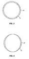
- the shape of the squish area 2 may be in a crescent moon shape as shown in Fig. 4 instead of an annular shape as in Fig. 3 .
- Fig. 5 is a sectional view obtained by cutting the combustion chamber 1 in Fig. 1 in a direction perpendicular to the sliding direction of the piston 16.
- a curved portion is given to the intake port 4 so that a swirl flow, that is, swirl can be given to the mixture.
- a center axis of the intake port 4 may be offset from the cylinder center, that is, the center of the combustion chamber 1 only by a.
- the squish or swirl is intended to promote mixture and not to expedite movement of flames according to gas fluidity.
- a plug hole 19 is shown.
- An ignition gap center 21 of the ignition plug 20 is located substantially at the center of the plug hole 19.
- Fig. 5 four ignition points 21 are provided and arranged at symmetrical or substantially symmetrical positions on a circumference of a diameter d.
- D is a diameter of the cylinder.
- Fig. 6 is an A-A sectional view of Fig. 5 .
- a conical dent 23 is disposed in the cylinder head 3 so that the ignition gap center 21 of the ignition plug 20 is located on the circumference of a base circle R along the combustion-chamber wall face 22.
- Fig. 7 three ignition points 21 are disposed, and the three ignition points 21 are arranged by offsetting the intake valve 6 and the intake port 4 from the cylinder center only by a so that a distance among the points 21 is equal. That is, with respect to a straight line connecting the arbitrary one ignition point 21 and the cylinder center, the remaining two ignition points 21 are located at line-symmetrical positions.
- Fig. 8 is a diagram corresponding to the Figs. 5 and 7 in the case of a prior-art two-point ignition engine.
- L 0.5 ⁇ D is considered to be optimal. This is because supposing that a flame progresses concentrically, a proportion of an initial combustion mass before interference of the flame is to be made large.
- T a distance from the ignition point 21 to the farthest position
- T a large pressure difference from the vicinity of the ignition point 21 is generated at this position immediately before combustion is finished, and there is a problem that leaning of mixture is limited.
- Fig. 9 is a map illustrating a relationship among the air excess ratio, heat efficiency, and the number of ignition points when the ignition timing ⁇ is constant
- a broken line portion in the figure means that too much leaning makes combustion unstable and the heat efficiency is lowered.
- the air excess ratio on the abscissa axis is a value obtained by dividing an air/ fuel ratio by a theoretical air/fuel ratio, and the air excess ratio is 1 when the air/fuel ratio is the theoretical air/fuel ratio.
- the heat efficiency 11 at ignition timing ⁇ when the target NOx level can be achieved is improved if the air excess ratio is increased.
- the air excess ratio in the case of two-point ignition is limited to approximately 1.4.
- stable operation can be realized in the case of the three-point ignition with the air excess ratio up to approximately 1.7 and in the case of four-point ignition with the air excess ratio up to approximately 2.0. Therefore, combustion with the number of ignition points of 3 or more and the air excess ratio of 1.5 or more is preferable.
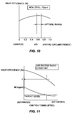
- Fig. 10 is a map illustrating a relationship between d/D and the heat efficiency when the NOx level is constant 0 on the abscissa axis is a state with one-point ignition at the center of the combustion chamber 1 and 1 on the abscissa axis is a state in which four ignition points are arranged on the entire circumference. With increase of an interval between the ignition points 21, the heat efficiency is improved and gradually lowered after reaching a peak. However, it is characteristic that the heat efficiency is higher with the multipoint ignition on the entire circumference than the central one-point ignition. As mentioned above the d/D is optimal at 0.55 to 0.7.
- Fig. 11 is a map illustrating a relationship among the ignition timing, the NOx level, and the heat efficiency when the air excess ratio is constant
- the NOx level is rapidly lowered at the beginning but the gradient becomes smaller.
- the gradient of the heat efficiency is getting larger. That is, if the heat efficiency is set too high, the target NOx level cannot be achieved.
- the ignition timing is retarded, and the ignition timing ⁇ and the heat efficiency with which the target NOx level can be achieved are acquired and they are used as parameters to obtain characteristics in Figs. 9 and 10 .
- the air excess ratio in the case of the three-point ignition is 1.7, for example, the heat efficiency that satisfies the target NOx level of 70 ppm can be acquired.
- Fig. 12 is a map illustrating a relationship between a crank angle and an in-cylinder pressure, in which a broken line is a gas pressure characteristic in motoring when only air is compressed and expanded without burning.
- the pressure rapidly rises after ignition and falls by expansion after reaching the peak.
- the peak point is indicated by Pmax.
- the ignition timing to become Pmax is 15° after the top dead center.
- the ignition timing to become Pmax is 9 to 12°. Since the lean mixture is rapidly burned in the compact combustion chamber 1 with a small surface area, knocking hardly occurs, and ⁇ to give Pmax can be advanced even if the compression ratio is high.
- a gas temperature is the highest at Pmax, and if the temperature at this time is 2070K (kelvin, 0 kelvin is -273°C) or less, the NOx level of 70 ppm can be achieved.
- the temperature at this time is 2070K (kelvin, 0 kelvin is -273°C) or less, the NOx level of 70 ppm can be achieved.
- the retardation always involves trade-off with the heat efficiency.
- the leaning can realize both reduction in the NOx level and improvement of the heat efficiency, but stable combustion at leaning needs to be ensured.
- the multipoint ignition engine of this embodiment can be applied to any fuel which starts combustion by spark ignition such as gasoline, urban gas, LPG, natural gas, biological fuel and the like.
Landscapes
- Engineering & Computer Science (AREA)
- Chemical & Material Sciences (AREA)
- Combustion & Propulsion (AREA)
- Mechanical Engineering (AREA)
- General Engineering & Computer Science (AREA)
- Signal Processing (AREA)
- Combustion Methods Of Internal-Combustion Engines (AREA)
- Cylinder Crankcases Of Internal Combustion Engines (AREA)
- Ignition Installations For Internal Combustion Engines (AREA)
Abstract
A bottom face of a cylinder head (3) defining a combustion chamber (1) is formed substantially in a shape of a spherical shell, and ignition points (21) are arranged in three or more on a concentric circle of 55 to 70% of a diameter of a cylinder block (30) or the vicinity thereof, and combustion is performed with an air excess ratio of the combustion chamber (1) of 1.5 or more.
Description
- The present invention relates to a multipoint ignition engine that realizes ultra lean combustion.
- In a spark ignition engine, it is known that ignition occurs at the center of a combustion chamber. Also, in
JP50-9454A - However, in an inexpensive small-sized engine for power generation or heat pump, for example, in order to make an air excess ratio extremely large (lean), to reduce a nitrogen oxide (NOx) level and to obtain high heat efficiency, a combustion speed needs to be improved rapidly than before, and a technique to ignite ultra lean mixture and rapidly burn it is indispensable.
- Here, there is a lean limit where a flame propagation speed is lowered and rotation of an engine becomes unstable if the mixture becomes lean, and this lean limit should be raised than before.
- The present invention has an object to realize ultra lean combustion by the shape of a combustion chamber and the number and a positional relationship of ignition points.
- In a multipoint ignition engine according to the present invention, in a spark ignition engine provided with a cylinder block, a piston sliding inside the cylinder block, a cylinder head provided at an upper part of the cylinder block, and ignition points for igniting a mixture in a combustion chamber defined by the cylinder block, the piston, and the cylinder head, a bottom face of the cylinder head defining the combustion chamber is formed substantially in a shape of a spherical shell, the ignition points are arranged in three or more on a concentric circle of 55 to 70% of a diameter of the cylinder block or its vicinity, and combustion is performed at an air excess ratio in the combustion chamber of 1.5 or more.
- According to the present invention, even with an extremely lean premixture mixed uniformly, simultaneous ignition at three points or more and stable combustion are realized, and since a part of the combustion chamber is formed as a spherical shell, an effect of gas fluidity by swirl or squish can be improved. Therefore, the air excess ratio can be raised so as to reduce NOx, and high heat efficiency can be realized.
-
-
Fig. 1 is an entire configuration diagram illustrating a configuration of a multipoint ignition engine in this embodiment -
Fig. 2 is an enlarged diagram for explaining a combustion chamber inFig. 1 . -
Fig. 3 is a perspective view ofFig. 2 seen from above. -
Fig. 4 is another embodiment ofFig. 3 . -
Fig. 5 is a sectional view obtained by cuttingFig. 1 in a direction perpendicular to a sliding direction of a piston. -
Fig. 6 is an A-A sectional view ofFig. 5 . -
Fig. 7 is another embodiment ofFig. 5 . -
Fig. 8 is a diagram corresponding toFigs. 5 and7 in the case of prior-art two-point ignition. -
Fig. 9 is a map illustrating a relationship among an air excess ratio, heat efficiency, and the number of ignition points when ignition timing θ is constant -
Fig. 10 is a map illustrating a relationship between d/D and heat efficiency when a NOx level is constant -
Fig. 11 is a map illustrating a relationship among the ignition timing, the NOx level, and heat efficiency when the air excess ratio is constant -
Fig. 12 is a map illustrating a relationship between a crank angle and an in-cylinder pressure. - Details of this embodiment will be described below referring to the attached drawings.
-
Fig. 1 is an entire configuration diagram illustrating a configuration of a multipoint ignition engine in thisembodiment A piston 16 is disposed vertically slidably in a cylinder and connected to a crank through a connecting rod.Fig. 1 shows a case in which thepiston 16 is at a top dead center, acombustion chamber 1 is defined by a top face of the piston and an inner wall of acylinder head 3 in this state, and a bottom face of thecylinder head 3 defining thecombustion chamber 1 is in a thin spherical shell shape with a radius R. Anintake valve 6 and anexhaust valve 8 are provided facing to thecombustion chamber 1, and an included angle between them is set small so as to be within 30°. - A capacity of the
combustion chamber 1 is determined so that a compression ratio, which is a value obtained by dividing the capacity of thecombustion chamber 1 when thepiston 16 is at a bottom dead center by the capacity of thecombustion chamber 1 when thepiston 16 is at the top dead center, is high. For example, the compression ratio when a fuel is natural gas is 13.2 or more. - To the
combustion chamber 1, anintake port 4 is connected through theintake valve 6, and anexhaust port 9 is connected through theexhaust valve 8. Air filtered by anair cleaner 11 is supplied with the fuel by aninjector 10 and taken into thecombustion chamber 1 as mixture according to opening / closing of theintake valve 6. This mixture is preferably mixed uniformly in the intake port before it enters thecombustion chamber 1. Also, exhaust gas after combustion is exhausted to theexhaust port 9 according to opening / closing of theexhaust valve 8. - On a portion other than an outer peripheral portion of the
cylinder block 30 and the intake /exhaust ports cylinder head 3,water jackets water inlet 13 into thewater jacket 12 of thecylinder block 30 and flows out to the outside from a cooling-water outlet 5 through thewater jacket 7 of thecylinder head 3. Thewater jacket 12 is disposed on the outer peripheral portion of thecylinder block 30 and an upper region above an upper end of thepiston 16 when thepiston 16 is at the bottom dead center. - Also, on an outer face of the
cylinder bock 30 and a region below the above-mentionedwater jacket 12, aninsulating material 14 for suppressing heat exchange between thecylinder block 30 and the outside is disposed. Similarly, aninsulating material 15 is also disposed above thecylinder block 30 and on the outer peripheral portion of thewater jacket 12. - By using heat deprived of from the engine by the cooling water for hot-water supply and heating, heat efficiency can be improved as an entire system, and by reducing the heat directly emitted from the surface of the engine to the air by radiation or convection by the
insulating materials -
Fig. 2 is an enlarged diagram of thecombustion chamber 1 inFig. 1 when thepiston 16 is at the top dead center.Fig. 3 is a diagram of asquish area 2 inFig. 2 seen from above. Thesquish area 2 is formed on the outer periphery portion of thecombustion chamber 1, and its thickness is approximately a head gasket In thissquish area 2, since an interval between thepiston 16 top face and the bottom face of thecylinder head 3 is reduced immediately before thepiston 16 reaches the top dead center, the mixture whose pressure has been raised is pushed out toward the center part of thecombustion chamber 1. - If a width of the
squish area 2 is too large, flame cannot reach thesquish area 2 but is cooled and exstinguished so that unburned hydrocarbon remains. Also, since cooling loss is increased by this unburned hydrocarbon, heat efficiency is deteriorated. Thus the width S of thesquish area 2 is approximately 2.5 mm or less. - Also, the shape of the
squish area 2 may be in a crescent moon shape as shown inFig. 4 instead of an annular shape as inFig. 3 . -
Fig. 5 is a sectional view obtained by cutting thecombustion chamber 1 inFig. 1 in a direction perpendicular to the sliding direction of thepiston 16. As shown inFig. 5 , a curved portion is given to theintake port 4 so that a swirl flow, that is, swirl can be given to the mixture. Also, as shown inFig. 7 , a center axis of theintake port 4 may be offset from the cylinder center, that is, the center of thecombustion chamber 1 only by a. - The squish or swirl is intended to promote mixture and not to expedite movement of flames according to gas fluidity.
- In this embodiment, in order to reduce combustion time of the mixture, three or more pieces of
ignition plugs 20 are disposed. InFig. 5 and7 , instead of theignition plug 20, anend portion 19 in a combustion-chamber wall face 22 of a mounting screw for theignition plug 20, that is, aplug hole 19 is shown. Anignition gap center 21 of theignition plug 20 is located substantially at the center of theplug hole 19. - In
Fig. 5 , fourignition points 21 are provided and arranged at symmetrical or substantially symmetrical positions on a circumference of a diameter d. The diameter d of the circle on which theignition points 21 are arranged is set to become d = (0.55 to 0.7)×D. Here, D is a diameter of the cylinder. -
Fig. 6 is an A-A sectional view ofFig. 5 . Aconical dent 23 is disposed in thecylinder head 3 so that theignition gap center 21 of theignition plug 20 is located on the circumference of a base circle R along the combustion-chamber wall face 22. - In
Fig. 7 , threeignition points 21 are disposed, and the threeignition points 21 are arranged by offsetting theintake valve 6 and theintake port 4 from the cylinder center only by a so that a distance among thepoints 21 is equal. That is, with respect to a straight line connecting the arbitrary oneignition point 21 and the cylinder center, the remaining twoignition points 21 are located at line-symmetrical positions. In this case, too, d is set as d = (0.55 to 0.7)×D similarly to the case of four points. -
Fig. 8 is a diagram corresponding to theFigs. 5 and7 in the case of a prior-art two-point ignition engine. As for a distance L between the two ignition gaps, L = 0.5×D is considered to be optimal. This is because supposing that a flame progresses concentrically, a proportion of an initial combustion mass before interference of the flame is to be made large. However, a distance from theignition point 21 to the farthest position is T, and a large pressure difference from the vicinity of theignition point 21 is generated at this position immediately before combustion is finished, and there is a problem that leaning of mixture is limited. - Subsequently, a method of determining the number, arrangement, air excess ratio and ignition timing of the ignition points 21 of the multipoint ignition engine in this embodiment will be described referring to
Figs. 9 to 11 . -
Fig. 9 is a map illustrating a relationship among the air excess ratio, heat efficiency, and the number of ignition points when the ignition timing θ is constant A broken line portion in the figure means that too much leaning makes combustion unstable and the heat efficiency is lowered. The air excess ratio on the abscissa axis is a value obtained by dividing an air/ fuel ratio by a theoretical air/fuel ratio, and the air excess ratio is 1 when the air/fuel ratio is the theoretical air/fuel ratio. - The
heat efficiency 11 at ignition timing θ when the target NOx level can be achieved is improved if the air excess ratio is increased. However, the air excess ratio in the case of two-point ignition is limited to approximately 1.4. On the other hand, stable operation can be realized in the case of the three-point ignition with the air excess ratio up to approximately 1.7 and in the case of four-point ignition with the air excess ratio up to approximately 2.0. Therefore, combustion with the number of ignition points of 3 or more and the air excess ratio of 1.5 or more is preferable. -
Fig. 10 is a map illustrating a relationship between d/D and the heat efficiency when the NOx level is constant 0 on the abscissa axis is a state with one-point ignition at the center of thecombustion chamber -
Fig. 11 is a map illustrating a relationship among the ignition timing, the NOx level, and the heat efficiency when the air excess ratio is constant InFig. 11 , as the ignition timing is retarded with the constant air excess ratio, the NOx level is rapidly lowered at the beginning but the gradient becomes smaller. On the other hand, the gradient of the heat efficiency is getting larger. That is, if the heat efficiency is set too high, the target NOx level cannot be achieved. - Thus, the ignition timing is retarded, and the ignition timing θ and the heat efficiency with which the target NOx level can be achieved are acquired and they are used as parameters to obtain characteristics in
Figs. 9 and10 . In this way, supposing that the air excess ratio in the case of the three-point ignition is 1.7, for example, the heat efficiency that satisfies the target NOx level of 70 ppm can be acquired. -
Fig. 12 is a map illustrating a relationship between a crank angle and an in-cylinder pressure, in which a broken line is a gas pressure characteristic in motoring when only air is compressed and expanded without burning. - The pressure rapidly rises after ignition and falls by expansion after reaching the peak. The peak point is indicated by Pmax. With the spark ignition engine using prior-art mixture which is uniformly mixed, the ignition timing to become Pmax is 15° after the top dead center.
- However, with the multipoint ignition engine in this embodiment, since extremely lean mixture with the air excess ratio of 1.7 is stably burned, the ignition timing to become Pmax is 9 to 12°. Since the lean mixture is rapidly burned in the
compact combustion chamber 1 with a small surface area, knocking hardly occurs, and θ to give Pmax can be advanced even if the compression ratio is high. - A gas temperature is the highest at Pmax, and if the temperature at this time is 2070K (kelvin, 0 kelvin is -273°C) or less, the NOx level of 70 ppm can be achieved. For that purpose, combination of leaning and retardation is needed, but the retardation always involves trade-off with the heat efficiency. On the other hand, the leaning can realize both reduction in the NOx level and improvement of the heat efficiency, but stable combustion at leaning needs to be ensured.
- Also, if the uniform mixture is distributed in the geometrically
symmetrical combustion chamber 1, simultaneous ignition is performed without providing a phase difference between the plurality of ignition plugs. As a result, a control system can be simplified. - The multipoint ignition engine of this embodiment can be applied to any fuel which starts combustion by spark ignition such as gasoline, urban gas, LPG, natural gas, biological fuel and the like.
Claims (6)
- A spark ignition engine comprising:a cylinder block;a piston sliding inside the cylinder block;a cylinder head disposed at an upper part of the cylinder block; andignition points for igniting mixture in a combustion chamber defined by the cylinder block, the piston, and the cylinder head, whereina bottom face of the cylinder head defining the combustion chamber is formed substantially in a spherical shell;the ignition points are arranged in three or more on a concentric circle of 55 to 70% of a diameter of the cylinder block or the vicinity thereof; andcombustion is performed with an air excess ratio in the combustion chamber of 1.5 or more.
- The spark ignition engine according to claim 1, wherein
the number of the ignition points is three or four. - The spark ignition engine according to claim 1, wherein
an intake port for taking intake into the combustion chamber has a curved portion or is offset from a center axis of the cylinder block. - The spark ignition engine according to claim 1, wherein
the number of the ignition points is three, and an intake port for taking intake into the combustion chamber is offset from a center axis of the cylinder block. - The spark ignition engine according to claim 1, further comprising:a connecting rod and a crank connected to the connecting rod for converting a motion of the piston to a rotational motion, whereinignition timing is set so that an angle of the crank when a pressure in the combustion chamber in an expansion stroke becomes the maximum is 9 to 12° after the piston comes to the top dead center.
- The spark ignition engine according to claim 1, further comprising:a water jacket disposed on an outer periphery portion of the cylinder block and through which cooling water communicates inside; andan insulating material disposed on the outer periphery portion of the cylinder block for suppressing heat transfer between the outer periphery portion and an outside, whereinthe water jacket is disposed on an upper region above an upper end of the piston when the piston reaches the bottom dead center and the insulating material is disposed on a region below the upper region.
Applications Claiming Priority (2)
| Application Number | Priority Date | Filing Date | Title |
|---|---|---|---|
| JP2007274025 | 2007-10-22 | ||
| PCT/JP2008/057371 WO2009054154A1 (en) | 2007-10-22 | 2008-04-09 | Multi-point ignition engine |
Publications (1)
| Publication Number | Publication Date |
|---|---|
| EP2202393A1 true EP2202393A1 (en) | 2010-06-30 |
Family
ID=40579262
Family Applications (1)
| Application Number | Title | Priority Date | Filing Date |
|---|---|---|---|
| EP08740457A Withdrawn EP2202393A1 (en) | 2007-10-22 | 2008-04-09 | Multi-point ignition engine |
Country Status (6)
| Country | Link |
|---|---|
| US (1) | US8196561B2 (en) |
| EP (1) | EP2202393A1 (en) |
| JP (1) | JP5131708B2 (en) |
| AU (1) | AU2008315238B2 (en) |
| CA (1) | CA2702679C (en) |
| WO (1) | WO2009054154A1 (en) |
Cited By (2)
| Publication number | Priority date | Publication date | Assignee | Title |
|---|---|---|---|---|
| DE102012208129A1 (en) * | 2012-05-15 | 2013-12-05 | Man Diesel & Turbo Se | Internal combustion engine |
| EP2955367A1 (en) * | 2014-06-12 | 2015-12-16 | Wojskowy Instytut Techniki Inzynieryjnej im. profesora Jozefa Kosackiego | An ignition system of a combustion engine |
Families Citing this family (10)
| Publication number | Priority date | Publication date | Assignee | Title |
|---|---|---|---|---|
| US8171898B2 (en) * | 2006-02-02 | 2012-05-08 | Avl List Gmbh | Crankcase breathing system |
| US8991355B2 (en) * | 2011-12-01 | 2015-03-31 | Loncin Motor Co., Ltd. | Cylinder head of small-sized general-purpose gasoline engine and gasoline engine having the same |
| US11022027B2 (en) * | 2016-11-18 | 2021-06-01 | Honda Motor Co., Ltd. | Internal combustion engine with reduced engine knocking |
| JP6217875B1 (en) * | 2017-02-14 | 2017-10-25 | トヨタ自動車株式会社 | Power train |
| JP6418280B2 (en) * | 2017-05-25 | 2018-11-07 | トヨタ自動車株式会社 | Power train |
| JP6386688B1 (en) * | 2018-05-16 | 2018-09-05 | 山崎 貴弘 | Simple emergency power supply device |
| JP6397152B1 (en) * | 2018-05-16 | 2018-09-26 | Ygk通商株式会社 | Simple emergency power supply device |
| JP6405069B1 (en) * | 2018-05-16 | 2018-10-17 | 山崎 貴弘 | Simple emergency power supply device |
| JP6375466B1 (en) * | 2018-05-16 | 2018-08-15 | Ygk通商株式会社 | Simple emergency power supply device |
| JP7325878B1 (en) | 2023-02-28 | 2023-08-15 | ライズピットカンパニー株式会社 | gas engine |
Family Cites Families (19)
| Publication number | Priority date | Publication date | Assignee | Title |
|---|---|---|---|---|
| US2756732A (en) * | 1954-03-17 | 1956-07-31 | Olson Donald Edward | Concentric intake and exhaust valves for internal combustion engines and the like |
| JPS509454A (en) | 1973-05-23 | 1975-01-30 | ||
| JPS5247088B2 (en) | 1975-01-22 | 1977-11-30 | ||
| JPS52109007A (en) * | 1976-03-11 | 1977-09-12 | Nissan Motor Co Ltd | Multi-point ignition engine |
| JPS5812457B2 (en) * | 1977-01-25 | 1983-03-08 | 工業技術院長 | hydrogen engine |
| US4202306A (en) * | 1977-03-10 | 1980-05-13 | Nissan Motor Company, Limited | Multi-point spark ignition engine provided with exhaust recirculation circuit |
| JPS5812457A (en) | 1981-07-15 | 1983-01-24 | Fujitsu Ltd | Storage communication system |
| US4452198A (en) * | 1982-06-28 | 1984-06-05 | General Motors Corporation | Compact dual spark internal combustion engine |
| JPS611853A (en) * | 1984-06-15 | 1986-01-07 | Nissan Motor Co Ltd | Control device of internal-combustion engine |
| JPS62182422A (en) * | 1986-02-05 | 1987-08-10 | Toyota Central Res & Dev Lab Inc | Stratified combustion engine |
| JP2808321B2 (en) | 1989-09-19 | 1998-10-08 | 東亜医用電子株式会社 | Cell analysis method and device |
| JP3105235B2 (en) * | 1990-03-30 | 2000-10-30 | マツダ株式会社 | engine |
| JPH0559951A (en) * | 1991-09-02 | 1993-03-09 | Yamaha Motor Co Ltd | Combustion control device of engine |
| JPH05302561A (en) * | 1992-04-27 | 1993-11-16 | Mazda Motor Corp | Combustion control device for multiignition engine |
| JP4496844B2 (en) * | 2004-05-19 | 2010-07-07 | いすゞ自動車株式会社 | Heat shield engine |
| JP2006266184A (en) * | 2005-03-24 | 2006-10-05 | Toyota Motor Corp | Engine block structure |
| JP4529764B2 (en) | 2005-03-31 | 2010-08-25 | マツダ株式会社 | 4 cycle spark ignition engine control device for vehicle |
| JP2007270844A (en) * | 2006-03-07 | 2007-10-18 | Miyama Kk | Multipoint ignition engine |
| JP2007239627A (en) * | 2006-03-09 | 2007-09-20 | Nissan Motor Co Ltd | Spark ignition internal combustion engine |
-
2008
- 2008-04-09 AU AU2008315238A patent/AU2008315238B2/en not_active Ceased
- 2008-04-09 WO PCT/JP2008/057371 patent/WO2009054154A1/en not_active Ceased
- 2008-04-09 CA CA2702679A patent/CA2702679C/en not_active Expired - Fee Related
- 2008-04-09 EP EP08740457A patent/EP2202393A1/en not_active Withdrawn
- 2008-04-09 US US12/734,250 patent/US8196561B2/en not_active Expired - Fee Related
- 2008-04-09 JP JP2009537950A patent/JP5131708B2/en not_active Expired - Fee Related
Non-Patent Citations (1)
| Title |
|---|
| See references of WO2009054154A1 * |
Cited By (2)
| Publication number | Priority date | Publication date | Assignee | Title |
|---|---|---|---|---|
| DE102012208129A1 (en) * | 2012-05-15 | 2013-12-05 | Man Diesel & Turbo Se | Internal combustion engine |
| EP2955367A1 (en) * | 2014-06-12 | 2015-12-16 | Wojskowy Instytut Techniki Inzynieryjnej im. profesora Jozefa Kosackiego | An ignition system of a combustion engine |
Also Published As
| Publication number | Publication date |
|---|---|
| WO2009054154A1 (en) | 2009-04-30 |
| US20100236504A1 (en) | 2010-09-23 |
| AU2008315238A1 (en) | 2009-04-30 |
| CA2702679A1 (en) | 2009-04-30 |
| JP5131708B2 (en) | 2013-01-30 |
| CA2702679C (en) | 2012-10-09 |
| JPWO2009054154A1 (en) | 2011-03-03 |
| US8196561B2 (en) | 2012-06-12 |
| AU2008315238B2 (en) | 2011-07-21 |
Similar Documents
| Publication | Publication Date | Title |
|---|---|---|
| US8196561B2 (en) | Multipoint ignition engine | |
| EP2659556B1 (en) | Prechamber ignition system | |
| EP3362658B1 (en) | Prechamber arrangement | |
| US6708666B2 (en) | Multi-zone combustion chamber for combustion rate shaping and emissions control in premixed-charge combustion engines | |
| WO2009109694A2 (en) | Pre-chamber arrangement | |
| CN110914525B (en) | Improved system and method for compression ignition engine | |
| EP2975237B1 (en) | Pre-chamber bottom section, pre-chamber, cylinder device, method for mixing of gas and air and ignition of the gas-air -mixture in a pre-chamber and a method for substituting a pre-chamber | |
| US4050420A (en) | Constant pressure-temperature delayed combustion high compression ratio engine and method | |
| EP2948657A1 (en) | Thermally stratified regenerative combustion chamber and method for modifying a combustion chamber in an internal combustion engine and resulting engine | |
| US4052972A (en) | Internal combustion engine | |
| CA2967005C (en) | Combustion chamber geometry | |
| EP3833859B1 (en) | Prechamber arrangement | |
| US20130263813A1 (en) | Cylinder head for an internal combustion engine | |
| WO2017155519A1 (en) | Pistons and internal combustion engines incorporating the same | |
| CN110131031A (en) | An Engine Ignition Chamber System with High Disturbance Composite Channels | |
| JP2019082168A (en) | Internal combustion engine directly injecting fuel in motion direction of intake air | |
| WO2006025743A2 (en) | Two-stroke internal combustion engine | |
| US12209552B2 (en) | Piston and internal combustion engine having such a piston | |
| US5343838A (en) | Dual radius rotor for pre-mixed-charge rotary engine combustion | |
| EP1896705A1 (en) | Combustion engine | |
| JP2021080892A (en) | Combustion chamber structure and spark ignition type internal combustion engine | |
| JPH07259563A (en) | Engine combustion control device | |
| CN105020020A (en) | Engine | |
| JPS6210419A (en) | Spark-ignition system internal-combustion engine | |
| WO2012144042A1 (en) | Control device for internal combustion engine |
Legal Events
| Date | Code | Title | Description |
|---|---|---|---|
| PUAI | Public reference made under article 153(3) epc to a published international application that has entered the european phase |
Free format text: ORIGINAL CODE: 0009012 |
|
| 17P | Request for examination filed |
Effective date: 20100413 |
|
| AK | Designated contracting states |
Kind code of ref document: A1 Designated state(s): AT BE BG CH CY CZ DE DK EE ES FI FR GB GR HR HU IE IS IT LI LT LU LV MC MT NL NO PL PT RO SE SI SK TR |
|
| AX | Request for extension of the european patent |
Extension state: AL BA MK RS |
|
| DAX | Request for extension of the european patent (deleted) | ||
| RAP1 | Party data changed (applicant data changed or rights of an application transferred) |
Owner name: YGK CO., LTD. |
|
| STAA | Information on the status of an ep patent application or granted ep patent |
Free format text: STATUS: THE APPLICATION IS DEEMED TO BE WITHDRAWN |
|
| 18D | Application deemed to be withdrawn |
Effective date: 20131101 |