EP2202346A2 - Device for hanging laundry provided with a vertical sliding system - Google Patents
Device for hanging laundry provided with a vertical sliding system Download PDFInfo
- Publication number
- EP2202346A2 EP2202346A2 EP09014392A EP09014392A EP2202346A2 EP 2202346 A2 EP2202346 A2 EP 2202346A2 EP 09014392 A EP09014392 A EP 09014392A EP 09014392 A EP09014392 A EP 09014392A EP 2202346 A2 EP2202346 A2 EP 2202346A2
- Authority
- EP
- European Patent Office
- Prior art keywords
- vertical sliding
- hanging laundry
- laundry
- sliding system
- hanging
- Prior art date
- Legal status (The legal status is an assumption and is not a legal conclusion. Google has not performed a legal analysis and makes no representation as to the accuracy of the status listed.)
- Withdrawn
Links
Images


Classifications
-
- D—TEXTILES; PAPER
- D06—TREATMENT OF TEXTILES OR THE LIKE; LAUNDERING; FLEXIBLE MATERIALS NOT OTHERWISE PROVIDED FOR
- D06F—LAUNDERING, DRYING, IRONING, PRESSING OR FOLDING TEXTILE ARTICLES
- D06F57/00—Supporting means, other than simple clothes-lines, for linen or garments to be dried or aired
- D06F57/12—Supporting means, other than simple clothes-lines, for linen or garments to be dried or aired specially adapted for attachment to walls, ceilings, stoves, or other structures or objects
Definitions
- Such a solution is characterised by a high longitudinal dimension and is not therefore suitable for hanging laundry in closed areas, necessary when unfavourable weather conditions occur.
- various alternative solutions have been proposed, able to limit spaces. They include proposed laundry racks with a vertical configuration composed of several quadrangular horizontal frames of reduced dimensions in relation to the horizontal frame of the structure described above. These frames are positioned at various levels on a base structure which extends in a vertical direction.
- the single horizontal frames are mobile and, thanks to the action of appropriate rotation means, can change from a closed configuration wherein they substantially extend one on the other to an open configuration wherein they form an angle of approximately 90 degrees in relation to the vertical base structure whereto they are constrained.
- Such a solution allows a reduction in the overall dimensions of the laundry rack only in a longitudinal direction and is not suitable for hanging laundry featuring a high length extension.
- the object of the present invention is therefore that of providing a device for hanging laundry in closed areas, mounted on the wall or independent, which maintains unchanged all the features of low cost, practicality and function of the known laundry racks with manual vertical sliding system, but which is provided with an automatic vertical sliding system and which is also able to simplify, without effort and in any case with greater comfort also for elderly people or those affected by particular motor disabilities, the operations of movement in a vertical direction of the rods for hanging laundry.
- This object is achieved by the insertion of a vertical sliding system made up of a hoisting assembly whereto, via two pulleys, two hoisting bands are connected, attached in turn to two tubular structures whereon the rods are mounted for hanging the laundry.
- This hoisting assembly is actuated by an already known electric motor reducer with single-phase or direct current power supply, controlled via a battery remote control or via a pushbutton panel.
- the device is made up of an assembly for hanging laundry (1) attached to two hoisting bands (2) in turn connected to a hoisting assembly (3), by means whereof said system for hanging laundry (1) is able to move in a vertical direction.
- said assembly for hanging laundry is made up of two tubular structures (4), preferably but not exclusively in aluminium, whereon the rods (5) for hanging laundry are mounted.
- Said tubular structures (4) are attached to two carriages (6), preferably in plastic, connected in turn to two hoisting bands (2).
- hoisting bands (2) translate in a vertical direction on two sliding rails (7) provided with two locking members (8).
- the rails may if necessary be attached also in other points by means of bi-adhesive tape, structural adhesives or rawl plugs.
- said hoisting bands are connected via two pulleys (9) to a tubular motor reducer (10) which can be powered both with direct current (for example via a battery) and with single-phase current.
- Said tubular motor reducer (10) and said pulleys (9) are contained inside a tubular structure (11), preferably but not exclusively in aluminium, at whose ends two closure members (12) are mounted which, each provided with a tongue (13), can act as a support for possible wall attachment.
- Said device for hanging laundry comprises, moreover, a receiver (14) for remote control or a pushbutton panel not shown in the drawings.
- Said device for hanging laundry may also comprise a system for the collapsing, in a direction parallel to said sliding rails, of the assembly for hanging laundry in conditions of non-use.
- a device for hanging laundry in closed areas, more particularly in the bathroom over the bath tub, mounted on the wall and provided with an automatic vertical sliding system based on the actuation of an electric motor reducer, able to meet the needs for space of many apartments and to be used without effort by elderly people or those affected by particular motor disabilities.
Landscapes
- Engineering & Computer Science (AREA)
- Textile Engineering (AREA)
- Power-Operated Mechanisms For Wings (AREA)
- Invalid Beds And Related Equipment (AREA)
- Treatment Of Fiber Materials (AREA)
Abstract
Description
- There are currently various structural solutions for laundry racks available on the market. The most common example is represented by folding laundry racks to be placed directly on the floor and consisting of a first frame which extends in a vertical direction and which constitutes the support structure for a second horizontal frame with quadrangular shape hinged to the first frame. In the second frame a series of rods are mounted which can be used as means whereon the laundry can be placed. These rods are mounted in a parallel direction to the longitudinal side of the quadrilateral and the end portions of each of them are anchored to the transverse side of the second frame or horizontal frame. In order to increase the surface which can be used for hanging the laundry, two lateral folding members are normally also mounted on the second frame or horizontal frame.
- Such a solution is characterised by a high longitudinal dimension and is not therefore suitable for hanging laundry in closed areas, necessary when unfavourable weather conditions occur. In order to avoid this disadvantage various alternative solutions have been proposed, able to limit spaces. They include proposed laundry racks with a vertical configuration composed of several quadrangular horizontal frames of reduced dimensions in relation to the horizontal frame of the structure described above. These frames are positioned at various levels on a base structure which extends in a vertical direction. The single horizontal frames are mobile and, thanks to the action of appropriate rotation means, can change from a closed configuration wherein they substantially extend one on the other to an open configuration wherein they form an angle of approximately 90 degrees in relation to the vertical base structure whereto they are constrained. Such a solution allows a reduction in the overall dimensions of the laundry rack only in a longitudinal direction and is not suitable for hanging laundry featuring a high length extension.
- Alternative solutions to the two presented hitherto are currently available on the market and which consist of laundry racks mounted on the ceiling or wall, usually placed in the bathroom above the bath tub and provided with vertical sliding systems consisting of a bar which, hinged at one end and translating in a vertical direction, is inserted in a hook catch and lowers to human level the rods for hanging the laundry.
- This solution, thanks to the wall or ceiling mount, partly solves the problem of the bulk of the laundry rack and of hanging of the laundry, in particular that with a considerable length extension, although the use of the vertical sliding system for the operations of lowering and raising of the rods for hanging the laundry may not always be easy, above all due to the load to be raised and more particularly by elderly people or those with motor difficulties.
- The object of the present invention is therefore that of providing a device for hanging laundry in closed areas, mounted on the wall or independent, which maintains unchanged all the features of low cost, practicality and function of the known laundry racks with manual vertical sliding system, but which is provided with an automatic vertical sliding system and which is also able to simplify, without effort and in any case with greater comfort also for elderly people or those affected by particular motor disabilities, the operations of movement in a vertical direction of the rods for hanging laundry.
- This object is achieved by the insertion of a vertical sliding system made up of a hoisting assembly whereto, via two pulleys, two hoisting bands are connected, attached in turn to two tubular structures whereon the rods are mounted for hanging the laundry. This hoisting assembly is actuated by an already known electric motor reducer with single-phase or direct current power supply, controlled via a battery remote control or via a pushbutton panel.
- This and further features of the present invention will be made clearer by the reading of the following detailed description, relating to a preferred embodiment of the present invention to be seen as a non-limiting example of the more general concepts claimed.
- The following description refers to the accompanying drawings, in which:
-
Figure 1 is a perspective view of the device with motor reducer controlled via a battery remote control. -
Figure 2a is a perspective view of the detail of the assembly for hanging laundry of the device with motor reducer controlled via battery remote control. -
Figure 2b is an exploded diagram of the detail of a sliding rail and of a locking member whereby translation in a vertical direction of the assembly for hanging laundry takes place. -
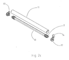
Figure 2c is an exploded diagram of the detail of the hoisting assembly of the device with motor reducer controlled via a single-phase or battery remote control. - Referring to
Figure 1 the device is made up of an assembly for hanging laundry (1) attached to two hoisting bands (2) in turn connected to a hoisting assembly (3), by means whereof said system for hanging laundry (1) is able to move in a vertical direction. - Referring to
Figure 2a said assembly for hanging laundry is made up of two tubular structures (4), preferably but not exclusively in aluminium, whereon the rods (5) for hanging laundry are mounted. Said tubular structures (4) are attached to two carriages (6), preferably in plastic, connected in turn to two hoisting bands (2). - Referring to
Figure 2b said hoisting bands (2) translate in a vertical direction on two sliding rails (7) provided with two locking members (8). The rails may if necessary be attached also in other points by means of bi-adhesive tape, structural adhesives or rawl plugs. - Referring to
Figure 2c said hoisting bands are connected via two pulleys (9) to a tubular motor reducer (10) which can be powered both with direct current (for example via a battery) and with single-phase current. - Said tubular motor reducer (10) and said pulleys (9) are contained inside a tubular structure (11), preferably but not exclusively in aluminium, at whose ends two closure members (12) are mounted which, each provided with a tongue (13), can act as a support for possible wall attachment.
- Said device for hanging laundry comprises, moreover, a receiver (14) for remote control or a pushbutton panel not shown in the drawings.
- Said device for hanging laundry may also comprise a system for the collapsing, in a direction parallel to said sliding rails, of the assembly for hanging laundry in conditions of non-use.
- Thus a device is provided for hanging laundry in closed areas, more particularly in the bathroom over the bath tub, mounted on the wall and provided with an automatic vertical sliding system based on the actuation of an electric motor reducer, able to meet the needs for space of many apartments and to be used without effort by elderly people or those affected by particular motor disabilities.
Claims (5)
- Device for hanging laundry provided with a vertical sliding system, characterised in that it is made up of an assembly for hanging laundry (1) comprising two horizontal tubular structures (4) whereon horizontal rods (5) are mounted whereon the laundry is placed, said assembly (1) being attached to at least two hoisting bands (2) connected via at least two pulleys (9) to a hoisting assembly (3).
- Device for hanging laundry provided with a vertical sliding system according to claim 1, characterised in that said hoisting assembly (3) is actuated by a tubular electric motor reducer (10).
- Device for hanging laundry provided with a vertical sliding system according to claims 1 and 2, characterised in that on said hoisting assembly (3) two closure members (12) can be mounted which, each provided with a tongue (13), can act as a support for possible attachment on a wall.
- Device for hanging laundry provided with a vertical sliding system according to claims 1, 2 and 3, characterised in that said electric motor reducer (10) can be controlled via a battery remote control.
- Device for hanging laundry provided with a vertical sliding system according to claims 1, 2, and 3, characterised in that said electric motor reducer (10) can be controlled via a pushbutton panel.
Applications Claiming Priority (1)
| Application Number | Priority Date | Filing Date | Title |
|---|---|---|---|
| ITMI20080423 ITMI20080423U1 (en) | 2008-12-22 | 2008-12-22 | DEVICE FOR DYEING THE CLOTHS EQUIPPED WITH A SLIDING SYSTEM |
Publications (2)
| Publication Number | Publication Date |
|---|---|
| EP2202346A2 true EP2202346A2 (en) | 2010-06-30 |
| EP2202346A3 EP2202346A3 (en) | 2012-02-15 |
Family
ID=42226081
Family Applications (1)
| Application Number | Title | Priority Date | Filing Date |
|---|---|---|---|
| EP09014392A Withdrawn EP2202346A3 (en) | 2008-12-22 | 2009-11-18 | Device for hanging laundry provided with a vertical sliding system |
Country Status (2)
| Country | Link |
|---|---|
| EP (1) | EP2202346A3 (en) |
| IT (1) | ITMI20080423U1 (en) |
Cited By (3)
| Publication number | Priority date | Publication date | Assignee | Title |
|---|---|---|---|---|
| CN102864618A (en) * | 2012-10-24 | 2013-01-09 | 成都理工大学 | Lifting pulley device of swing-out clothes hanger |
| CN104233725A (en) * | 2014-09-26 | 2014-12-24 | 邹思佳 | Cantilever clothes hanger |
| CN104674529A (en) * | 2015-03-11 | 2015-06-03 | 上海海事大学 | Intelligent self-adaption airing system |
Family Cites Families (6)
| Publication number | Priority date | Publication date | Assignee | Title |
|---|---|---|---|---|
| DE9102820U1 (en) * | 1991-03-07 | 1991-05-23 | Hackober, Norbert, O-1034 Berlin | Tumble dryer |
| CN2243480Y (en) * | 1995-11-21 | 1996-12-25 | 揭西县南光塑料制品厂 | Screw rod-pulley transmission for electric driving drying rods |
| US6149020A (en) * | 1998-09-10 | 2000-11-21 | Gumpel; Tomas P. | Ceiling hung clothesline support |
| DE202005007919U1 (en) * | 2005-05-20 | 2005-08-11 | Byczek, Edward | Unit for drying items of laundry comprises a housing accommodating a frame and a drive which by means of pulleys and cords is joined to a vertically movable lattice structure |
| DE102006053981B4 (en) * | 2006-11-10 | 2008-10-02 | Zoran Divkovic | Device for hanging a tumble dryer |
| KR100859283B1 (en) * | 2008-05-07 | 2008-09-19 | (주) 대동종합건설 | Clothes dryer |
-
2008
- 2008-12-22 IT ITMI20080423 patent/ITMI20080423U1/en unknown
-
2009
- 2009-11-18 EP EP09014392A patent/EP2202346A3/en not_active Withdrawn
Cited By (3)
| Publication number | Priority date | Publication date | Assignee | Title |
|---|---|---|---|---|
| CN102864618A (en) * | 2012-10-24 | 2013-01-09 | 成都理工大学 | Lifting pulley device of swing-out clothes hanger |
| CN104233725A (en) * | 2014-09-26 | 2014-12-24 | 邹思佳 | Cantilever clothes hanger |
| CN104674529A (en) * | 2015-03-11 | 2015-06-03 | 上海海事大学 | Intelligent self-adaption airing system |
Also Published As
| Publication number | Publication date |
|---|---|
| EP2202346A3 (en) | 2012-02-15 |
| ITMI20080423U1 (en) | 2010-06-23 |
Similar Documents
| Publication | Publication Date | Title |
|---|---|---|
| US9420881B2 (en) | Vertically retractable shelving for home or office | |
| US4915461A (en) | Storage cabinet retrieval system | |
| US6454336B1 (en) | Narrow width slide-out room support system | |
| US8157108B1 (en) | Pull-out, drop-down closet storage system | |
| AU2018248119B2 (en) | A wardrobe apparatus | |
| CN104619230A (en) | Dish rack | |
| EP2202346A2 (en) | Device for hanging laundry provided with a vertical sliding system | |
| EP0281605B1 (en) | A shower cabinet | |
| US20170210272A1 (en) | Camping car having electric bed frame | |
| KR102403573B1 (en) | Roof top tent for vehicle | |
| US11723457B2 (en) | Overhead storage unit | |
| CN201426523Y (en) | Elevatable wall cabinet | |
| US20070056094A1 (en) | So-called fold-away bed | |
| CN210236817U (en) | Handrail device for elevator car | |
| ITMO980245A1 (en) | MECHANIZED CABINET FOR HANGED CLOTHES WITH FACILITATED STORAGE. | |
| CN212489252U (en) | Multifunctional sofa bed device with tea table | |
| KR20210121965A (en) | A high and low control type bad for camping car | |
| CN114475408B (en) | Multifunctional modular intelligent motor home | |
| CN209595104U (en) | Ergonomic storage device | |
| KR100605563B1 (en) | Movable Volume Structure | |
| US20060255701A1 (en) | Storage cabinet | |
| CN217174105U (en) | Telescopic airing rack structure and storage cabinet | |
| CN213524385U (en) | Rotary electric heating table | |
| CN212852967U (en) | Medical environmental protection nurse station convenient to nurse has a rest | |
| CN215126034U (en) | A new type of storage cabinet for placing blocking devices |
Legal Events
| Date | Code | Title | Description |
|---|---|---|---|
| PUAI | Public reference made under article 153(3) epc to a published international application that has entered the european phase |
Free format text: ORIGINAL CODE: 0009012 |
|
| AK | Designated contracting states |
Kind code of ref document: A2 Designated state(s): AT BE BG CH CY CZ DE DK EE ES FI FR GB GR HR HU IE IS IT LI LT LU LV MC MK MT NL NO PL PT RO SE SI SK SM TR |
|
| AX | Request for extension of the european patent |
Extension state: AL BA RS |
|
| PUAL | Search report despatched |
Free format text: ORIGINAL CODE: 0009013 |
|
| RIC1 | Information provided on ipc code assigned before grant |
Ipc: D06F 57/12 20060101AFI20120104BHEP |
|
| AK | Designated contracting states |
Kind code of ref document: A3 Designated state(s): AT BE BG CH CY CZ DE DK EE ES FI FR GB GR HR HU IE IS IT LI LT LU LV MC MK MT NL NO PL PT RO SE SI SK SM TR |
|
| AX | Request for extension of the european patent |
Extension state: AL BA RS |
|
| RIC1 | Information provided on ipc code assigned before grant |
Ipc: D06F 57/12 20060101AFI20120214BHEP |
|
| STAA | Information on the status of an ep patent application or granted ep patent |
Free format text: STATUS: THE APPLICATION IS DEEMED TO BE WITHDRAWN |
|
| 18D | Application deemed to be withdrawn |
Effective date: 20120817 |