EP2202345A1 - Manufacturing process of an appliance cabinet and cabinet so manufactured - Google Patents
Manufacturing process of an appliance cabinet and cabinet so manufactured Download PDFInfo
- Publication number
- EP2202345A1 EP2202345A1 EP08022448A EP08022448A EP2202345A1 EP 2202345 A1 EP2202345 A1 EP 2202345A1 EP 08022448 A EP08022448 A EP 08022448A EP 08022448 A EP08022448 A EP 08022448A EP 2202345 A1 EP2202345 A1 EP 2202345A1
- Authority
- EP
- European Patent Office
- Prior art keywords
- bar
- manufacturing process
- modular units
- process according
- cabinet
- Prior art date
- Legal status (The legal status is an assumption and is not a legal conclusion. Google has not performed a legal analysis and makes no representation as to the accuracy of the status listed.)
- Granted
Links
- 238000004519 manufacturing process Methods 0.000 title claims abstract description 43
- 238000005452 bending Methods 0.000 claims abstract description 7
- 230000008878 coupling Effects 0.000 claims abstract description 5
- 238000010168 coupling process Methods 0.000 claims abstract description 5
- 238000005859 coupling reaction Methods 0.000 claims abstract description 5
- 238000000034 method Methods 0.000 claims description 6
- 230000008569 process Effects 0.000 claims description 4
- 238000003466 welding Methods 0.000 claims description 3
- 238000001125 extrusion Methods 0.000 claims description 2
- NLYAJNPCOHFWQQ-UHFFFAOYSA-N kaolin Chemical compound O.O.O=[Al]O[Si](=O)O[Si](=O)O[Al]=O NLYAJNPCOHFWQQ-UHFFFAOYSA-N 0.000 claims description 2
- 238000005520 cutting process Methods 0.000 claims 1
- 230000008859 change Effects 0.000 description 1
- 238000010276 construction Methods 0.000 description 1
- 238000010412 laundry washing Methods 0.000 description 1
- 238000012423 maintenance Methods 0.000 description 1
- 230000013011 mating Effects 0.000 description 1
- 238000012986 modification Methods 0.000 description 1
- 230000004048 modification Effects 0.000 description 1
- 230000003014 reinforcing effect Effects 0.000 description 1
Images




Classifications
-
- D—TEXTILES; PAPER
- D06—TREATMENT OF TEXTILES OR THE LIKE; LAUNDERING; FLEXIBLE MATERIALS NOT OTHERWISE PROVIDED FOR
- D06F—LAUNDERING, DRYING, IRONING, PRESSING OR FOLDING TEXTILE ARTICLES
- D06F39/00—Details of washing machines not specific to a single type of machines covered by groups D06F9/00 - D06F27/00
- D06F39/12—Casings; Tubs
Definitions
- the present invention relates to a manufacturing process of a cabinet for appliances, in particular household appliances, and an appliance cabinet so manufactured.
- a first arrangement comprises a carrying structure for supporting appliance operating components that is closed by substantially planar panels.
- Said carrying structure may be formed by a box element made of a sheet material bent to an L configuration so as to comprise in a single piece the bottom and a vertical rear wall of the cabinet.
- the carrying structure is completed by a panel disposed opposite to said vertical wall and connected thereto by means of two upper rails.
- Planar panels are removable from the carrying structure to give access to the appliance operating components while the latter continue to be supported by the carrying structure.
- a cabinet of this type i.e. a cabinet wherein some of its outer walls has a support function for the appliance operational components, is disclosed in the European Patent EP 0208334 .
- a structure of this type does not offer sufficient rigidity and requires complicated, time-consuming and thus expensive assembly operations, in particular, it appears rather impractical and inconvenient that the carrying structure for the appliance operating components is formed by a box element made of a sheet material cut to measure and bent to an L configuration.
- the manufacturing process of such cabinet arrangement cannot be adapted easily to the production of cabinets having different shapes and dimensions without heavy modifications both in the process steps and in the production equipments.
- an appliance cabinet comprises a supporting frame made of spars, mountings and crossbars on which operational components of the appliance are attached and a plurality of panels removably mounted on the frame.
- a cabinet of this type i.e. a cabinet wherein the outer walls have no supporting function is disclosed in the French Patent Application FR 1 520 703 .
- a drawback of this second arrangement is that the supporting frame has to be dimensioned specifically for each kind of appliance according to its volume and overall dimensions. An adjustment of the frame structure dimensions requires necessarily a change of its bar components, therefore a manufacturing process for producing this kind of cabinet is rigid, i.e. unsuitable to be adapted to production of cabinets having different dimensions.
- a further drawback of such known cabinets is that assembling operations require to weld or fasten each end portion of bars forming the supporting frame. The assembling process results therefore rather long and complicated.
- the aim of the present invention is therefore to solve the noted problems, eliminating the drawbacks of the cited known art and thus providing a manufacturing process of an appliance cabinet allowing the production of cabinets having different dimensional characteristics without modifying the procedural steps of the process.
- Another purpose of the present invention is to provide a manufacturing process of an appliance cabinet that simplifies the cabinet assembling operations and reduces the number of productive equipments needed for making an appliance cabinet.
- a further purpose of the present invention is to provide a manufacturing process of an appliance cabinet wherein the use of standardized components and prefabricated articles is advantageously maximised and the production costs and power consumption are drastically reduced.
- Still another purpose of the present invention is to provide a manufacturing process of an appliance cabinet wherein the time needed for completing the cabinet assembling operations is reduced compared to known cabinet manufacturing processes.
- Another purpose of the present invention is to provide a manufacturing process for the production of cabinets for different uses such as cabinets for household appliance, for electric equipments and so on.
- a purpose of the present invention is to provide an appliance cabinet ensuring an easy and prompt access to the inner region of the cabinet itself, thereby simplifying maintenance operations of appliance operational components housed within the cabinet.
- Still another purpose of the present invention is to provide an appliance cabinet wherein the outer panels of the cabinet have no supporting function for operational components of an appliance.
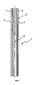
- a section bar 1 is used in the manufacturing process according to the invention for forming a plurality of modular units 10, 210 ( figures 4 and 9 ) which, in turn, are used to compose a supporting frame as it will be diffusely described below.
- a section bar 1 suitable for carrying out the manufacturing process of the present invention can be obtained easily by extrusion of a metallic mass.
- Section bar 1 can have a band-like shape as shown in figure 1 and 2 or it can be formed by two substantially perpendicular elongated walls protruding from a common line of intersection B. Said walls give the bar 1 a substantially L-shaped cross section wherein each wall forms an arm of the "L".
- the same L-shaped cross section, useful for the construction of a modular unit 10, 210, can be also easily formed starting from a section bar 1 having a band-like shape, i.e. a substantially flat shape, by bending the bar 1 itself along a longitudinal direction B.
- bar 1 comprises a plurality of longitudinal ribs 5 extending along the whole length of the section bar 1.
- Said ribs 5 form two conjugated surfaces 6 and 7 arranged on opposite sides of the bar 1 respectively on the left and right portions of bar 1 with respect to the longitudinal direction B, i.e. the longitudinal bending line. In this way surfaces 6 and 7 of two section bars 1 can be slidably coupled.
- each end region 2 of a section bar 1 is cut along a longitudinal direction so as to form two bar portions 3 and 4.
- the longitudinal cut line coincides with the longitudinal direction B on which the bar 1 is bent to give it a L-shaped cross-section, in this way each bar portion 3, 4 carries one of said conjugated surfaces 6 and 7 placed on opposite sides of the bar 1.
- FIG 3 it is shown how a modular unit 10 made according to a first embodiment is formed by bending bar portions 3 and 4 of each end region 2 of a section bar 1.
- Bar portions 3 and 4 are bent one above the other such that, at the end of the bending operation (see figures 4 to 7 ) , a right angle ⁇ is comprised between portions 3, 4 and a further right angle ⁇ is formed between each portion 3, 4 and a bar part 8 extending between the two opposite end regions 2.
- said bar part 8 forms at least a part of an edge of a supporting frame for an appliance cabinet. Overlapping of portions 3 and 4 is favoured by the L-shaped cross section of bar 1. If needed, seats 9 ( figure 6 and 7 ) can be formed on one of said portions 3, 4 to allow one of them to lie down on the other one without forming creases.
- a modular unit 10 made according to a first embodiment has a three dimensional shape reproducing preferably the whole edge and angular portion of a box-like structure.
- Bar portions 3, 4 of two opposite ends of the same modular unit 10 lie on two parallel planes and are two by two parallel.
- bar portions 3, 4 carrying the same conjugated surface 6, 7 are bent so as to be placed on the same side relative to the bar part 8. Even if in figures 4 and 5 modular unit 10 has been shown with bar portions 3, 4 of equal length, it is possible to form such portions 3, 4 having different extensions.
- a supporting frame 11 can be formed associating each other four modular units 10 made according to a first embodiment.
- Modular units 10 associating step of a manufacturing process according to the invention can be made by simply fixing each other bar portions 3, 4 of said units 10 for example through welding of by fastening means known per se.
- first conjugated surface 7 carried by first bar portion 3
- second conjugated surface 6 carried by second bar portion 4.
- Ribs 5 provided on conjugated surfaces 6 and 7 avoid portions 3 and 4 to slip in a transversal direction with respect to the longitudinal sliding direction.
- a slidable connection between portions 3, 4 of two modular units 10 allows a manufacturer to adjust the reciprocal positions of said units according to the final dimension required by the appliance cabinet. Such adjustment of the frame 11 dimensions is performed before reciprocally fixing said modular units 10. In this way the same modular units 10 can be used for the production of a large variety of supporting frames 11, and consequently of appliance cabinets, differing only in dimensions and volume.
- overlapping regions of portions 3, 4 are useful for reinforcing and stiffening the supporting frame.
- Arrows W and D indicate how the first and second conjugated surfaces 6 and 7 can be mated.
- the same arrows W, D represent also the directions (width and depth) along which dimensions of a supporting frame 11 can be adjusted.
- modular units 10 are fixed by welding and/or by fastening means known per sè, such as screws, rivets and the like.
- Modular units fixing step takes place in the overlapping region of portions 3 and 4.
- the so formed supporting frame 11 is shown in figure 10 and serves as a structure on which all operational components of the appliance can be attached. Particular arrangements may be provided on the supporting frame so as to facilitate the attachment of said operational components.
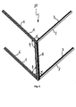
- FIG 9 it is shown a supporting frame 211 to be assembled using eight modular units 210 made according to a second embodiment.
- elements in common with the first embodiment have been referenced with the same numbers.
- a modular unit 210 made according to a second embodiment has a three dimensional shape reproducing an angular portion and part of an edge portion of a supporting frame 211.
- Such second embodiment of modular unit 210 allows to adjust not only width and depth of the supporting frame 211 as described with reference to figure 8 , but also its height. Width and depth of a supporting frame 211 to be formed with eight modular units 210 are adjusted simply sliding a first bar portion 3 of a first modular unit 210 onto a second bar portion 4 of a second modular unit 210 identical to the first one through conjugated surfaces 6, 7 until a predetermined reciprocal position of such units 210 is reached.
- Arrows W and D in figure 9 show the directions along which frame 211 dimensions can be adjusted by means of a sliding movement of one conjugated surface 6, 7 onto the other.
- overlapping bar portions 3, 4 of two associated units 210 are joined in a manner described with reference to the frame 11 obtained with modular units 10 made according to a first embodiment and depicted in figure 8 .
- This process step is made for all the four modular units 210 forming the upper part of frame 211 and for all the four units 210 forming the lower part of the same frame 211.
- connecting members 13 having, preferably, an L-shaped form so as to perfectly adhere to bar part 8.
- Connecting members 13 are provided because conjugated surfaces 6, 7 on vertical bar part 8 cannot overlap once width and depth of supporting frame 211 have been fixed.
- a selective height adjustment of frame 211 along directions indicated by arrows H shown in figure 9 can be achieved by providing a plurality of holes 14 arranged on members 13 such that each end region 2 of modular units 210 can be fixed on said members 13 in a plurality of positions.
- holes 15 passing through conjugated surfaces 6, 7 are provided on the end region 2 opposite to the bar portions 3, 4 of each modular unit 210.
- holes 15 are aligned with holes 14 provided on connecting members 13 for receiving a fastening means like a screw, a bolt or a rivet.
- left upper and lower modular units 210 are shown with the respective end regions 2 in contact, i.e. in a configuration suitable to obtain the minimum height allowed by connecting members 13.
- a slot/pin coupling can be provided between connecting members 13 and end regions 2 of bar parts 8, so as to define a range of infinite reciprocal positions between a maximum and minimum height for the upper and lower frame 211 parts.
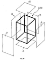
- FIG 10 it is shown how an appliance cabinet is completed by removably associating one or more panels 12 to a supporting frame 11, 211.
- Said panels 12 may be easily attached to the frame 11, 211 by snap connectors or threaded connectors not shown in figure 10 . In this way, panels 12 can be easily removed when access to operational components of the appliance is needed.
- panels 12 have been schematically represented as surfaces covering completely each face of the supporting frame 11, 211, however, if desired, each of said face can be covered by two or more panels 12. This may be the case wherein the supporting frame 11, 211 is part of a laundry treating machine, or another household appliance having a door for accessing an inner region of an operational component of the appliance and a control panel for driving the appliance work.
- a cabinet produced with a manufacturing process according to the invention has a simplified structure and it is easy to be assembled.
- the same cabinet allows a manufacturer to reduce necessary equipments for carrying out its production.
- a manufacturing process according to the present invention can be used for the production of cabinets for many different kinds of appliances, in particular household appliances, like dishwashers, refrigerators, ovens, laundry treating machines, more particularly clothes dryers and laundry washing machines.
- appliances having cabinets of different volume and dimensions can be easily produced without changing the manufacturing process steps.
- said inventive process is advantageously versatile, economically convenient and realizable by means of automatic machines.
Landscapes
- Engineering & Computer Science (AREA)
- Textile Engineering (AREA)
- Casings For Electric Apparatus (AREA)
Abstract
Description
- The present invention relates to a manufacturing process of a cabinet for appliances, in particular household appliances, and an appliance cabinet so manufactured.
- It is known that an appliance cabinet can be manufactured substantially according to two arrangements. A first arrangement comprises a carrying structure for supporting appliance operating components that is closed by substantially planar panels. Said carrying structure may be formed by a box element made of a sheet material bent to an L configuration so as to comprise in a single piece the bottom and a vertical rear wall of the cabinet. The carrying structure is completed by a panel disposed opposite to said vertical wall and connected thereto by means of two upper rails. Planar panels are removable from the carrying structure to give access to the appliance operating components while the latter continue to be supported by the carrying structure. A cabinet of this type, i.e. a cabinet wherein some of its outer walls has a support function for the appliance operational components, is disclosed in the European Patent
EP 0208334 . A structure of this type does not offer sufficient rigidity and requires complicated, time-consuming and thus expensive assembly operations, in particular, it appears rather impractical and inconvenient that the carrying structure for the appliance operating components is formed by a box element made of a sheet material cut to measure and bent to an L configuration. In fact, the manufacturing process of such cabinet arrangement cannot be adapted easily to the production of cabinets having different shapes and dimensions without heavy modifications both in the process steps and in the production equipments. - According to a second generally known arrangement, an appliance cabinet comprises a supporting frame made of spars, mountings and crossbars on which operational components of the appliance are attached and a plurality of panels removably mounted on the frame. A cabinet of this type, i.e. a cabinet wherein the outer walls have no supporting function is disclosed in the French
Patent Application FR 1 520 703 - A drawback of this second arrangement is that the supporting frame has to be dimensioned specifically for each kind of appliance according to its volume and overall dimensions. An adjustment of the frame structure dimensions requires necessarily a change of its bar components, therefore a manufacturing process for producing this kind of cabinet is rigid, i.e. unsuitable to be adapted to production of cabinets having different dimensions. A further drawback of such known cabinets is that assembling operations require to weld or fasten each end portion of bars forming the supporting frame. The assembling process results therefore rather long and complicated.
- The aim of the present invention is therefore to solve the noted problems, eliminating the drawbacks of the cited known art and thus providing a manufacturing process of an appliance cabinet allowing the production of cabinets having different dimensional characteristics without modifying the procedural steps of the process.
- Another purpose of the present invention is to provide a manufacturing process of an appliance cabinet that simplifies the cabinet assembling operations and reduces the number of productive equipments needed for making an appliance cabinet.
- A further purpose of the present invention is to provide a manufacturing process of an appliance cabinet wherein the use of standardized components and prefabricated articles is advantageously maximised and the production costs and power consumption are drastically reduced.
- Still another purpose of the present invention is to provide a manufacturing process of an appliance cabinet wherein the time needed for completing the cabinet assembling operations is reduced compared to known cabinet manufacturing processes.
- Another purpose of the present invention is to provide a manufacturing process for the production of cabinets for different uses such as cabinets for household appliance, for electric equipments and so on.
- A purpose of the present invention is to provide an appliance cabinet ensuring an easy and prompt access to the inner region of the cabinet itself, thereby simplifying maintenance operations of appliance operational components housed within the cabinet.
- Still another purpose of the present invention is to provide an appliance cabinet wherein the outer panels of the cabinet have no supporting function for operational components of an appliance.
- Advantages, objects, and features of the invention will be set forth in part in the description which follows and in part will become apparent to those having ordinary skill in the art upon examination of the following or may be learned from practice of the invention. The objects and advantages of the invention may be realised and attained as particularly pointed out in the appended claims.
- The accompanying drawings, which are included to provide a further understanding of the invention and are incorporated in and constitute a part of this specification, illustrate a possible embodiment of the invention and together with the description serve to explain the principles of the invention.
- In the drawings:
-
Figure 1 shows an end portion of a section bar used in the manufacturing process according to the invention for the production of a modular unit forming a supporting frame; -
Figure 2 shows a cross section view of the bar crop shown infigure 1 ; -
Figure 3 a left and right perspective view of a first embodiment of a modular unit in a step of its forming; -
Figure 4 shows a inner perspective view of a first embodiment of a modular unit; -
Figure 5 shows an outer perspective view of a first embodiment of a modular unit; -
Figure 6 shows a inner perspective view of an angular portion of a modular unit; -
Figure 7 shows an outer perspective view of an angular portion of a modular unit; -
Figure 8 shows a perspective view of a partially disassembled frame structure formed in a step of the appliance cabinet manufacturing process according to the present invention by using a first embodiment of the modular unit; -
Figure 9 shows a perspective view of a partially disassembled frame structure formed in a step of the appliance cabinet manufacturing process according to the present invention by using a second embodiment of the modular unit; -
Figure 10 schematically shows a second step of the appliance cabinet manufacturing process according to the present invention; - Referring to
figure 1 , asection bar 1 is used in the manufacturing process according to the invention for forming a plurality ofmodular units 10, 210 (figures 4 and9 ) which, in turn, are used to compose a supporting frame as it will be diffusely described below. Asection bar 1 suitable for carrying out the manufacturing process of the present invention can be obtained easily by extrusion of a metallic mass.Section bar 1 can have a band-like shape as shown infigure 1 and2 or it can be formed by two substantially perpendicular elongated walls protruding from a common line of intersection B. Said walls give the bar 1 a substantially L-shaped cross section wherein each wall forms an arm of the "L". The same L-shaped cross section, useful for the construction of amodular unit section bar 1 having a band-like shape, i.e. a substantially flat shape, by bending thebar 1 itself along a longitudinal direction B. - As shown in
figure 2 ,bar 1 comprises a plurality oflongitudinal ribs 5 extending along the whole length of thesection bar 1. Saidribs 5 form two conjugatedsurfaces bar 1 respectively on the left and right portions ofbar 1 with respect to the longitudinal direction B, i.e. the longitudinal bending line. In thisway surfaces section bars 1 can be slidably coupled. - According to a first embodiment of a
modular unit 10 shown infigures 3 - 5, 8 , eachend region 2 of asection bar 1 is cut along a longitudinal direction so as to form twobar portions figure 1 , the longitudinal cut line coincides with the longitudinal direction B on which thebar 1 is bent to give it a L-shaped cross-section, in this way eachbar portion conjugated surfaces bar 1. - In
figure 3 it is shown how amodular unit 10 made according to a first embodiment is formed bybending bar portions end region 2 of asection bar 1. In such figure a right and left view of thesame bar 1 is disclosed.Bar portions figures 4 to 7 ) , a right angle α is comprised betweenportions portion bar part 8 extending between the twoopposite end regions 2. As it is diffusely described below, saidbar part 8 forms at least a part of an edge of a supporting frame for an appliance cabinet. Overlapping ofportions bar 1. If needed, seats 9 (figure 6 and7 ) can be formed on one of saidportions - A
modular unit 10 made according to a first embodiment has a three dimensional shape reproducing preferably the whole edge and angular portion of a box-like structure.Bar portions modular unit 10 lie on two parallel planes and are two by two parallel. In addition,bar portions conjugated surface bar part 8. Even if infigures 4 and5 modular unit 10 has been shown withbar portions such portions - With reference to
figure 8 , a supportingframe 11 can be formed associating each other fourmodular units 10 made according to a first embodiment.Modular units 10 associating step of a manufacturing process according to the invention can be made by simply fixing eachother bar portions units 10 for example through welding of by fastening means known per se. However, it is preferable first slidably coupling afirst bar portion 3 of a firstmodular unit 10 to asecond bar portion 4 of a secondmodular unit 10 identical to the first one simply mating a first conjugatedsurface 7 carried byfirst bar portion 3 with a second conjugatedsurface 6 carried bysecond bar portion 4. As the association betweenportions conjugated surfaces bar 1. -
Ribs 5 provided on conjugatedsurfaces portions portions modular units 10 allows a manufacturer to adjust the reciprocal positions of said units according to the final dimension required by the appliance cabinet. Such adjustment of theframe 11 dimensions is performed before reciprocally fixing saidmodular units 10. In this way the samemodular units 10 can be used for the production of a large variety of supportingframes 11, and consequently of appliance cabinets, differing only in dimensions and volume. In addition overlapping regions ofportions - Arrows W and D indicate how the first and second
conjugated surfaces frame 11 can be adjusted. - Once the reciprocal positions of
modular units 10 have been determined according to the dimensions of the appliance cabinet to be produced,modular units 10 are fixed by welding and/or by fastening means known per sè, such as screws, rivets and the like. Modular units fixing step takes place in the overlapping region ofportions frame 11 is shown infigure 10 and serves as a structure on which all operational components of the appliance can be attached. Particular arrangements may be provided on the supporting frame so as to facilitate the attachment of said operational components. - In
figure 9 it is shown a supportingframe 211 to be assembled using eightmodular units 210 made according to a second embodiment. In said second embodiment elements in common with the first embodiment have been referenced with the same numbers. - As far as the
bar portions modular unit 210 is made exactly as already described with reference to thefirst embodiment 10. Even thesection bar 1 can be the same for both embodiments. As it is clear fromfigure 9 , the only difference between the two proposed embodiments consists in that, in the secondmodular unit 210 embodiment,bar portions end region 2 ofbar 1, leaving the other end region 2 L-shaped formed.Bar portions modular unit 210 have the same constructional and spatial arrangement described with reference to the first embodiment, and therefore it will not further described here. - A
modular unit 210 made according to a second embodiment has a three dimensional shape reproducing an angular portion and part of an edge portion of a supportingframe 211. Such second embodiment ofmodular unit 210 allows to adjust not only width and depth of the supportingframe 211 as described with reference tofigure 8 , but also its height. Width and depth of a supportingframe 211 to be formed with eightmodular units 210 are adjusted simply sliding afirst bar portion 3 of a firstmodular unit 210 onto asecond bar portion 4 of a secondmodular unit 210 identical to the first one throughconjugated surfaces such units 210 is reached. Arrows W and D infigure 9 show the directions along whichframe 211 dimensions can be adjusted by means of a sliding movement of oneconjugated surface units 210 are placed in the desired position, overlappingbar portions units 210 are joined in a manner described with reference to theframe 11 obtained withmodular units 10 made according to a first embodiment and depicted infigure 8 . - This process step is made for all the four
modular units 210 forming the upper part offrame 211 and for all the fourunits 210 forming the lower part of thesame frame 211. - When the upper and lower part of
frame 211 are completed, such parts can be joined through connectingmembers 13 having, preferably, an L-shaped form so as to perfectly adhere to barpart 8. Connectingmembers 13 are provided becauseconjugated surfaces vertical bar part 8 cannot overlap once width and depth of supportingframe 211 have been fixed. A selective height adjustment offrame 211 along directions indicated by arrows H shown infigure 9 can be achieved by providing a plurality ofholes 14 arranged onmembers 13 such that eachend region 2 ofmodular units 210 can be fixed on saidmembers 13 in a plurality of positions. For fasteningmodular units 210 tomembers 13, holes 15 passing throughconjugated surfaces end region 2 opposite to thebar portions modular unit 210. Before reciprocally fixing the upper and lower part of theframe 211, holes 15 are aligned withholes 14 provided on connectingmembers 13 for receiving a fastening means like a screw, a bolt or a rivet. - In
figure 9 , left upper and lowermodular units 210 are shown with therespective end regions 2 in contact, i.e. in a configuration suitable to obtain the minimum height allowed by connectingmembers 13. - Evidently, if a continuous adjustment of
frame 211 height along directions indicated by arrows H is desired, instead ofholes members 13 andend regions 2 ofbar parts 8, so as to define a range of infinite reciprocal positions between a maximum and minimum height for the upper andlower frame 211 parts. - In
figure 10 it is shown how an appliance cabinet is completed by removably associating one ormore panels 12 to a supportingframe panels 12 may be easily attached to theframe figure 10 . In this way,panels 12 can be easily removed when access to operational components of the appliance is needed. Infigure 10 ,panels 12 have been schematically represented as surfaces covering completely each face of the supportingframe more panels 12. This may be the case wherein the supportingframe - Conclusively it can be stated that a cabinet produced with a manufacturing process according to the invention has a simplified structure and it is easy to be assembled. The same cabinet allows a manufacturer to reduce necessary equipments for carrying out its production.
- Advantageously a manufacturing process according to the present invention can be used for the production of cabinets for many different kinds of appliances, in particular household appliances, like dishwashers, refrigerators, ovens, laundry treating machines, more particularly clothes dryers and laundry washing machines. According to the proposed invention, appliances having cabinets of different volume and dimensions can be easily produced without changing the manufacturing process steps. Hence, said inventive process is advantageously versatile, economically convenient and realizable by means of automatic machines.
Claims (15)
- Manufacturing process of an appliance cabinet characterised by comprising the following steps: (a) providing a plurality of modular units (10, 210), each of them being formed by: (a1) providing a section bar (1) having a pair of end regions (2) and a bar part (8) comprised between said end regions (2), (a2) on at least one end region (2) of said section bar (1), forming two bar portions (3, 4), (a3) bending said portions (3, 4) one above the other such that a substantially right angle (α, β) is formed between them and between each of said portion (3, 4) and said bar part (8); (b) adjusting the reciprocal position of said modular units (10, 210) along at least one direction (W, D, H); (c) associating said modular units (10, 210) thereby forming a supporting frame (11, 211); (d) removably associating at least one panel (12) to said supporting frame (11, 211).
- Manufacturing process according to claim 1 wherein step (b) is carried out by slidably coupling conjugated surfaces (6, 7) formed on said bar portions (3, 4) of two adjacent modular units (10, 210).
- Manufacturing process according to claim 1 or 2 wherein step (b) is carried out in one direction (H) by means of connecting members (13) provided with means for selectively or continuously adjust the reciprocal position between two plurality of modular units (10, 210).
- Manufacturing process according to claim 3 wherein said means for selectively or continuously adjust the reciprocal position between two plurality of modular units (10, 210) comprises holes (14, 15) or slot/pin like couplings.
- Manufacturing process according to any preceding claim wherein said section bar (1) has a substantially L-shaped cross section.
- Manufacturing process according to claim 5 wherein said L-shaped cross section is obtained by bending said section bar (1) along a longitudinal direction (B).
- Manufacturing process according to any preceding claim wherein in step (a2) said bar portions (3, 4) are made by cutting at least a part of each bar end region (2) along a longitudinal direction (B).
- Manufacturing process according to any preceding claim wherein said section bar (1) is made by extrusion and comprises conjugated surfaces (6, 7) formed on opposite sides of said bar (1).
- Manufacturing process according to any preceding claim wherein step (c) comprises a welding process;
- Manufacturing process according to any preceding claim wherein in step (d) said panels (12) are attached to the supporting frame (11, 211) by snap connectors or threaded connectors.
- Appliance cabinet manufactured with a manufacturing process according to any claim 1 to 10 comprising a supporting frame (11, 211) and at least one panel (12) removably attached to said frame (11, 211) characterised in that the frame (11, 211) comprises modular units (10, 210), each of them forming angular portion and at least a part of an edge portion of said cabinet.
- Appliance cabinet according to claim 11 wherein each of said modular units (10, 210) is made in a single piece.
- Appliance cabinet according to claim 10 or 11 wherein each of said modular units (10, 210) comprises bent portions (3, 4) having first and second conjugated surfaces (6, 7) adapted to be slidably coupled respectively to second and first conjugated surfaces (6, 7) of a second modular unit (10, 210).
- Appliance cabinet according to any claim 11 to 13 wherein each of said modular units (10, 210) comprises a section bar (1) having a pair of end regions (2) and a bar part (8) comprised between said end regions (2), at least one of said end regions (2) comprising two portions (3, 4) bent one above the other such that a substantially right angle (α, β) is formed between them and between each of said portion (3, 4) and said bar part (8).
- Household appliance comprising a cabinet according to any claim 11 to 14.
Priority Applications (1)
| Application Number | Priority Date | Filing Date | Title |
|---|---|---|---|
| EP08022448.8A EP2202345B1 (en) | 2008-12-24 | 2008-12-24 | Manufacturing process of an appliance cabinet and cabinet so manufactured |
Applications Claiming Priority (1)
| Application Number | Priority Date | Filing Date | Title |
|---|---|---|---|
| EP08022448.8A EP2202345B1 (en) | 2008-12-24 | 2008-12-24 | Manufacturing process of an appliance cabinet and cabinet so manufactured |
Publications (2)
| Publication Number | Publication Date |
|---|---|
| EP2202345A1 true EP2202345A1 (en) | 2010-06-30 |
| EP2202345B1 EP2202345B1 (en) | 2017-03-01 |
Family
ID=40651324
Family Applications (1)
| Application Number | Title | Priority Date | Filing Date |
|---|---|---|---|
| EP08022448.8A Not-in-force EP2202345B1 (en) | 2008-12-24 | 2008-12-24 | Manufacturing process of an appliance cabinet and cabinet so manufactured |
Country Status (1)
| Country | Link |
|---|---|
| EP (1) | EP2202345B1 (en) |
Citations (5)
| Publication number | Priority date | Publication date | Assignee | Title |
|---|---|---|---|---|
| GB966231A (en) * | 1960-01-20 | 1964-08-06 | Esswein Et Cie Soc | Improvements in or relating to washing machines |
| FR1520703A (en) | 1967-03-01 | 1968-04-12 | Chalectro Cie Des Machiens A L | Cage frame washing machine |
| EP0208334A2 (en) | 1985-07-11 | 1987-01-14 | INDUSTRIE ZANUSSI S.p.A. | Housing for a laundry washing machine |
| DE3810647A1 (en) * | 1988-03-29 | 1989-10-12 | Licentia Gmbh | Connection of the housing casing and bottom part in household implements, in particular in washing machines which can be loaded from above |
| DE19706285A1 (en) * | 1997-02-18 | 1998-08-20 | Bosch Siemens Hausgeraete | Rectangular cover for a household machine |
-
2008
- 2008-12-24 EP EP08022448.8A patent/EP2202345B1/en not_active Not-in-force
Patent Citations (5)
| Publication number | Priority date | Publication date | Assignee | Title |
|---|---|---|---|---|
| GB966231A (en) * | 1960-01-20 | 1964-08-06 | Esswein Et Cie Soc | Improvements in or relating to washing machines |
| FR1520703A (en) | 1967-03-01 | 1968-04-12 | Chalectro Cie Des Machiens A L | Cage frame washing machine |
| EP0208334A2 (en) | 1985-07-11 | 1987-01-14 | INDUSTRIE ZANUSSI S.p.A. | Housing for a laundry washing machine |
| DE3810647A1 (en) * | 1988-03-29 | 1989-10-12 | Licentia Gmbh | Connection of the housing casing and bottom part in household implements, in particular in washing machines which can be loaded from above |
| DE19706285A1 (en) * | 1997-02-18 | 1998-08-20 | Bosch Siemens Hausgeraete | Rectangular cover for a household machine |
Also Published As
| Publication number | Publication date |
|---|---|
| EP2202345B1 (en) | 2017-03-01 |
Similar Documents
| Publication | Publication Date | Title |
|---|---|---|
| EP0104497B1 (en) | Laundry washing machine of modular construction | |
| US4798424A (en) | Reversible control console | |
| US9297109B2 (en) | Laundry dryer | |
| EP2638199B1 (en) | A washer/dryer comprising a connection member | |
| KR100353026B1 (en) | Cabinet of clothes washing machine | |
| AU2003251176B2 (en) | Cabinet for home appliance | |
| AU2008221776A1 (en) | Laundry treating apparatus and method of manufacturing a front cover for a laundry treating apparatus | |
| WO2008124911A1 (en) | Improvement in cabinet for electronic components | |
| EP1978310B1 (en) | Modular oven structure | |
| EP2202345B1 (en) | Manufacturing process of an appliance cabinet and cabinet so manufactured | |
| KR101084116B1 (en) | Door of drum washing machine | |
| KR20060089083A (en) | Drum Washing Machine | |
| EP2527748B1 (en) | An oven with a front panel | |
| GB2168387A (en) | Enclosing structure for clothes washing machine | |
| EP1164672B1 (en) | Cabinet for electrical switchboard | |
| EP0208334B1 (en) | Housing for a laundry washing machine | |
| CN209669525U (en) | Device for clothing processing | |
| CN209669546U (en) | Braced frame and device for clothing processing | |
| KR100441099B1 (en) | A leg bracket's installing structure of the washer | |
| KR100867278B1 (en) | washer | |
| EP0579064B1 (en) | Laundry washing machine with a cabinet having rigid vertical walls | |
| EP0385675A1 (en) | Improvements in and relating to tubular bodies | |
| CN115707817B (en) | Clothing processing apparatus box structure and clothing processing apparatus | |
| CN116919292B (en) | Connection structure between cavity and base of dishwasher and dishwasher | |
| EP3712516B1 (en) | Wall-mounted indoor air conditioner unit |
Legal Events
| Date | Code | Title | Description |
|---|---|---|---|
| PUAI | Public reference made under article 153(3) epc to a published international application that has entered the european phase |
Free format text: ORIGINAL CODE: 0009012 |
|
| AK | Designated contracting states |
Kind code of ref document: A1 Designated state(s): AT BE BG CH CY CZ DE DK EE ES FI FR GB GR HR HU IE IS IT LI LT LU LV MC MT NL NO PL PT RO SE SI SK TR |
|
| AX | Request for extension of the european patent |
Extension state: AL BA MK RS |
|
| 17P | Request for examination filed |
Effective date: 20101230 |
|
| 17Q | First examination report despatched |
Effective date: 20110124 |
|
| AKX | Designation fees paid |
Designated state(s): AT BE BG CH CY CZ DE DK EE ES FI FR GB GR HR HU IE IS IT LI LT LU LV MC MT NL NO PL PT RO SE SI SK TR |
|
| RAP1 | Party data changed (applicant data changed or rights of an application transferred) |
Owner name: ELECTROLUX HOME PRODUCTS CORPORATION N.V. |
|
| RAP1 | Party data changed (applicant data changed or rights of an application transferred) |
Owner name: ELECTROLUX HOME PRODUCTS CORPORATION N.V. |
|
| GRAP | Despatch of communication of intention to grant a patent |
Free format text: ORIGINAL CODE: EPIDOSNIGR1 |
|
| INTG | Intention to grant announced |
Effective date: 20161013 |
|
| GRAS | Grant fee paid |
Free format text: ORIGINAL CODE: EPIDOSNIGR3 |
|
| GRAA | (expected) grant |
Free format text: ORIGINAL CODE: 0009210 |
|
| AK | Designated contracting states |
Kind code of ref document: B1 Designated state(s): AT BE BG CH CY CZ DE DK EE ES FI FR GB GR HR HU IE IS IT LI LT LU LV MC MT NL NO PL PT RO SE SI SK TR |
|
| REG | Reference to a national code |
Ref country code: GB Ref legal event code: FG4D |
|
| REG | Reference to a national code |
Ref country code: CH Ref legal event code: EP Ref country code: AT Ref legal event code: REF Ref document number: 871471 Country of ref document: AT Kind code of ref document: T Effective date: 20170315 |
|
| REG | Reference to a national code |
Ref country code: IE Ref legal event code: FG4D |
|
| REG | Reference to a national code |
Ref country code: DE Ref legal event code: R096 Ref document number: 602008048904 Country of ref document: DE |
|
| REG | Reference to a national code |
Ref country code: NL Ref legal event code: MP Effective date: 20170301 |
|
| REG | Reference to a national code |
Ref country code: LT Ref legal event code: MG4D |
|
| REG | Reference to a national code |
Ref country code: AT Ref legal event code: MK05 Ref document number: 871471 Country of ref document: AT Kind code of ref document: T Effective date: 20170301 |
|
| PG25 | Lapsed in a contracting state [announced via postgrant information from national office to epo] |
Ref country code: HR Free format text: LAPSE BECAUSE OF FAILURE TO SUBMIT A TRANSLATION OF THE DESCRIPTION OR TO PAY THE FEE WITHIN THE PRESCRIBED TIME-LIMIT Effective date: 20170301 Ref country code: LT Free format text: LAPSE BECAUSE OF FAILURE TO SUBMIT A TRANSLATION OF THE DESCRIPTION OR TO PAY THE FEE WITHIN THE PRESCRIBED TIME-LIMIT Effective date: 20170301 Ref country code: NO Free format text: LAPSE BECAUSE OF FAILURE TO SUBMIT A TRANSLATION OF THE DESCRIPTION OR TO PAY THE FEE WITHIN THE PRESCRIBED TIME-LIMIT Effective date: 20170601 Ref country code: FI Free format text: LAPSE BECAUSE OF FAILURE TO SUBMIT A TRANSLATION OF THE DESCRIPTION OR TO PAY THE FEE WITHIN THE PRESCRIBED TIME-LIMIT Effective date: 20170301 Ref country code: GR Free format text: LAPSE BECAUSE OF FAILURE TO SUBMIT A TRANSLATION OF THE DESCRIPTION OR TO PAY THE FEE WITHIN THE PRESCRIBED TIME-LIMIT Effective date: 20170602 |
|
| PG25 | Lapsed in a contracting state [announced via postgrant information from national office to epo] |
Ref country code: ES Free format text: LAPSE BECAUSE OF FAILURE TO SUBMIT A TRANSLATION OF THE DESCRIPTION OR TO PAY THE FEE WITHIN THE PRESCRIBED TIME-LIMIT Effective date: 20170301 Ref country code: SE Free format text: LAPSE BECAUSE OF FAILURE TO SUBMIT A TRANSLATION OF THE DESCRIPTION OR TO PAY THE FEE WITHIN THE PRESCRIBED TIME-LIMIT Effective date: 20170301 Ref country code: AT Free format text: LAPSE BECAUSE OF FAILURE TO SUBMIT A TRANSLATION OF THE DESCRIPTION OR TO PAY THE FEE WITHIN THE PRESCRIBED TIME-LIMIT Effective date: 20170301 Ref country code: BG Free format text: LAPSE BECAUSE OF FAILURE TO SUBMIT A TRANSLATION OF THE DESCRIPTION OR TO PAY THE FEE WITHIN THE PRESCRIBED TIME-LIMIT Effective date: 20170601 Ref country code: LV Free format text: LAPSE BECAUSE OF FAILURE TO SUBMIT A TRANSLATION OF THE DESCRIPTION OR TO PAY THE FEE WITHIN THE PRESCRIBED TIME-LIMIT Effective date: 20170301 |
|
| PG25 | Lapsed in a contracting state [announced via postgrant information from national office to epo] |
Ref country code: NL Free format text: LAPSE BECAUSE OF FAILURE TO SUBMIT A TRANSLATION OF THE DESCRIPTION OR TO PAY THE FEE WITHIN THE PRESCRIBED TIME-LIMIT Effective date: 20170301 |
|
| PG25 | Lapsed in a contracting state [announced via postgrant information from national office to epo] |
Ref country code: SK Free format text: LAPSE BECAUSE OF FAILURE TO SUBMIT A TRANSLATION OF THE DESCRIPTION OR TO PAY THE FEE WITHIN THE PRESCRIBED TIME-LIMIT Effective date: 20170301 Ref country code: EE Free format text: LAPSE BECAUSE OF FAILURE TO SUBMIT A TRANSLATION OF THE DESCRIPTION OR TO PAY THE FEE WITHIN THE PRESCRIBED TIME-LIMIT Effective date: 20170301 Ref country code: CZ Free format text: LAPSE BECAUSE OF FAILURE TO SUBMIT A TRANSLATION OF THE DESCRIPTION OR TO PAY THE FEE WITHIN THE PRESCRIBED TIME-LIMIT Effective date: 20170301 Ref country code: IT Free format text: LAPSE BECAUSE OF FAILURE TO SUBMIT A TRANSLATION OF THE DESCRIPTION OR TO PAY THE FEE WITHIN THE PRESCRIBED TIME-LIMIT Effective date: 20170301 Ref country code: RO Free format text: LAPSE BECAUSE OF FAILURE TO SUBMIT A TRANSLATION OF THE DESCRIPTION OR TO PAY THE FEE WITHIN THE PRESCRIBED TIME-LIMIT Effective date: 20170301 |
|
| PG25 | Lapsed in a contracting state [announced via postgrant information from national office to epo] |
Ref country code: IS Free format text: LAPSE BECAUSE OF FAILURE TO SUBMIT A TRANSLATION OF THE DESCRIPTION OR TO PAY THE FEE WITHIN THE PRESCRIBED TIME-LIMIT Effective date: 20170701 Ref country code: PL Free format text: LAPSE BECAUSE OF FAILURE TO SUBMIT A TRANSLATION OF THE DESCRIPTION OR TO PAY THE FEE WITHIN THE PRESCRIBED TIME-LIMIT Effective date: 20170301 Ref country code: PT Free format text: LAPSE BECAUSE OF FAILURE TO SUBMIT A TRANSLATION OF THE DESCRIPTION OR TO PAY THE FEE WITHIN THE PRESCRIBED TIME-LIMIT Effective date: 20170703 |
|
| REG | Reference to a national code |
Ref country code: DE Ref legal event code: R097 Ref document number: 602008048904 Country of ref document: DE |
|
| PLBE | No opposition filed within time limit |
Free format text: ORIGINAL CODE: 0009261 |
|
| STAA | Information on the status of an ep patent application or granted ep patent |
Free format text: STATUS: NO OPPOSITION FILED WITHIN TIME LIMIT |
|
| PG25 | Lapsed in a contracting state [announced via postgrant information from national office to epo] |
Ref country code: DK Free format text: LAPSE BECAUSE OF FAILURE TO SUBMIT A TRANSLATION OF THE DESCRIPTION OR TO PAY THE FEE WITHIN THE PRESCRIBED TIME-LIMIT Effective date: 20170301 |
|
| 26N | No opposition filed |
Effective date: 20171204 |
|
| PG25 | Lapsed in a contracting state [announced via postgrant information from national office to epo] |
Ref country code: SI Free format text: LAPSE BECAUSE OF FAILURE TO SUBMIT A TRANSLATION OF THE DESCRIPTION OR TO PAY THE FEE WITHIN THE PRESCRIBED TIME-LIMIT Effective date: 20170301 |
|
| REG | Reference to a national code |
Ref country code: CH Ref legal event code: PL |
|
| GBPC | Gb: european patent ceased through non-payment of renewal fee |
Effective date: 20171224 |
|
| REG | Reference to a national code |
Ref country code: IE Ref legal event code: MM4A |
|
| PG25 | Lapsed in a contracting state [announced via postgrant information from national office to epo] |
Ref country code: MT Free format text: LAPSE BECAUSE OF NON-PAYMENT OF DUE FEES Effective date: 20171224 Ref country code: LU Free format text: LAPSE BECAUSE OF NON-PAYMENT OF DUE FEES Effective date: 20171224 |
|
| REG | Reference to a national code |
Ref country code: FR Ref legal event code: ST Effective date: 20180831 |
|
| REG | Reference to a national code |
Ref country code: BE Ref legal event code: MM Effective date: 20171231 |
|
| PG25 | Lapsed in a contracting state [announced via postgrant information from national office to epo] |
Ref country code: FR Free format text: LAPSE BECAUSE OF NON-PAYMENT OF DUE FEES Effective date: 20180102 Ref country code: IE Free format text: LAPSE BECAUSE OF NON-PAYMENT OF DUE FEES Effective date: 20171224 |
|
| PG25 | Lapsed in a contracting state [announced via postgrant information from national office to epo] |
Ref country code: LI Free format text: LAPSE BECAUSE OF NON-PAYMENT OF DUE FEES Effective date: 20171231 Ref country code: BE Free format text: LAPSE BECAUSE OF NON-PAYMENT OF DUE FEES Effective date: 20171231 Ref country code: GB Free format text: LAPSE BECAUSE OF NON-PAYMENT OF DUE FEES Effective date: 20171224 Ref country code: CH Free format text: LAPSE BECAUSE OF NON-PAYMENT OF DUE FEES Effective date: 20171231 |
|
| PG25 | Lapsed in a contracting state [announced via postgrant information from national office to epo] |
Ref country code: MC Free format text: LAPSE BECAUSE OF FAILURE TO SUBMIT A TRANSLATION OF THE DESCRIPTION OR TO PAY THE FEE WITHIN THE PRESCRIBED TIME-LIMIT Effective date: 20170301 Ref country code: HU Free format text: LAPSE BECAUSE OF FAILURE TO SUBMIT A TRANSLATION OF THE DESCRIPTION OR TO PAY THE FEE WITHIN THE PRESCRIBED TIME-LIMIT; INVALID AB INITIO Effective date: 20081224 |
|
| PG25 | Lapsed in a contracting state [announced via postgrant information from national office to epo] |
Ref country code: CY Free format text: LAPSE BECAUSE OF NON-PAYMENT OF DUE FEES Effective date: 20170301 |
|
| PG25 | Lapsed in a contracting state [announced via postgrant information from national office to epo] |
Ref country code: TR Free format text: LAPSE BECAUSE OF FAILURE TO SUBMIT A TRANSLATION OF THE DESCRIPTION OR TO PAY THE FEE WITHIN THE PRESCRIBED TIME-LIMIT Effective date: 20170301 |
|
| PGFP | Annual fee paid to national office [announced via postgrant information from national office to epo] |
Ref country code: DE Payment date: 20211210 Year of fee payment: 14 |
|
| REG | Reference to a national code |
Ref country code: DE Ref legal event code: R119 Ref document number: 602008048904 Country of ref document: DE |
|
| PG25 | Lapsed in a contracting state [announced via postgrant information from national office to epo] |
Ref country code: DE Free format text: LAPSE BECAUSE OF NON-PAYMENT OF DUE FEES Effective date: 20230701 |