EP2202183A1 - Gripper device for conveying circular tube body - Google Patents
Gripper device for conveying circular tube body Download PDFInfo
- Publication number
- EP2202183A1 EP2202183A1 EP08832673A EP08832673A EP2202183A1 EP 2202183 A1 EP2202183 A1 EP 2202183A1 EP 08832673 A EP08832673 A EP 08832673A EP 08832673 A EP08832673 A EP 08832673A EP 2202183 A1 EP2202183 A1 EP 2202183A1
- Authority
- EP
- European Patent Office
- Prior art keywords
- conveying
- fork
- members
- bottle
- chain
- Prior art date
- Legal status (The legal status is an assumption and is not a legal conclusion. Google has not performed a legal analysis and makes no representation as to the accuracy of the status listed.)
- Granted
Links
- 230000006835 compression Effects 0.000 abstract description 3
- 238000007906 compression Methods 0.000 abstract description 3
- 238000000034 method Methods 0.000 description 9
- 239000000843 powder Substances 0.000 description 8
- 239000000428 dust Substances 0.000 description 3
- 229920003002 synthetic resin Polymers 0.000 description 3
- 239000000057 synthetic resin Substances 0.000 description 3
- 239000002184 metal Substances 0.000 description 2
- 238000006748 scratching Methods 0.000 description 2
- 230000002393 scratching effect Effects 0.000 description 2
- 238000005452 bending Methods 0.000 description 1
- 238000005520 cutting process Methods 0.000 description 1
- 239000013013 elastic material Substances 0.000 description 1
- 238000005429 filling process Methods 0.000 description 1
- 230000005484 gravity Effects 0.000 description 1
- 238000004519 manufacturing process Methods 0.000 description 1
- 239000000463 material Substances 0.000 description 1
- 238000012986 modification Methods 0.000 description 1
- 230000004048 modification Effects 0.000 description 1
- 238000007747 plating Methods 0.000 description 1
- 229920005989 resin Polymers 0.000 description 1
- 239000011347 resin Substances 0.000 description 1
- 230000035939 shock Effects 0.000 description 1
- 229910001220 stainless steel Inorganic materials 0.000 description 1
- 239000010935 stainless steel Substances 0.000 description 1
- 238000004381 surface treatment Methods 0.000 description 1
- 238000011144 upstream manufacturing Methods 0.000 description 1
- 238000005406 washing Methods 0.000 description 1
- XLYOFNOQVPJJNP-UHFFFAOYSA-N water Substances O XLYOFNOQVPJJNP-UHFFFAOYSA-N 0.000 description 1
Images


Classifications
-
- B—PERFORMING OPERATIONS; TRANSPORTING
- B65—CONVEYING; PACKING; STORING; HANDLING THIN OR FILAMENTARY MATERIAL
- B65G—TRANSPORT OR STORAGE DEVICES, e.g. CONVEYORS FOR LOADING OR TIPPING, SHOP CONVEYOR SYSTEMS OR PNEUMATIC TUBE CONVEYORS
- B65G17/00—Conveyors having an endless traction element, e.g. a chain, transmitting movement to a continuous or substantially-continuous load-carrying surface or to a series of individual load-carriers; Endless-chain conveyors in which the chains form the load-carrying surface
- B65G17/30—Details; Auxiliary devices
- B65G17/32—Individual load-carriers
- B65G17/323—Grippers, e.g. suction or magnetic
-
- B—PERFORMING OPERATIONS; TRANSPORTING
- B65—CONVEYING; PACKING; STORING; HANDLING THIN OR FILAMENTARY MATERIAL
- B65G—TRANSPORT OR STORAGE DEVICES, e.g. CONVEYORS FOR LOADING OR TIPPING, SHOP CONVEYOR SYSTEMS OR PNEUMATIC TUBE CONVEYORS
- B65G47/00—Article or material-handling devices associated with conveyors; Methods employing such devices
- B65G47/74—Feeding, transfer, or discharging devices of particular kinds or types
- B65G47/84—Star-shaped wheels or devices having endless travelling belts or chains, the wheels or devices being equipped with article-engaging elements
- B65G47/841—Devices having endless travelling belts or chains equipped with article-engaging elements
- B65G47/842—Devices having endless travelling belts or chains equipped with article-engaging elements the article-engaging elements being grippers
-
- B—PERFORMING OPERATIONS; TRANSPORTING
- B65—CONVEYING; PACKING; STORING; HANDLING THIN OR FILAMENTARY MATERIAL
- B65G—TRANSPORT OR STORAGE DEVICES, e.g. CONVEYORS FOR LOADING OR TIPPING, SHOP CONVEYOR SYSTEMS OR PNEUMATIC TUBE CONVEYORS
- B65G2201/00—Indexing codes relating to handling devices, e.g. conveyors, characterised by the type of product or load being conveyed or handled
- B65G2201/02—Articles
- B65G2201/0235—Containers
- B65G2201/0244—Bottles
- B65G2201/0247—Suspended bottles
Definitions
- This invention relates to a gripper device for conveying a cylindrical body and, more particularly, to a device which, in a case where a PET bottle or a preform before forming of a bottle is conveyed by gripping a neck portion of the PET bottle or the preform with a pair of fork-members provided on a conveyer chain, can receive the PET bottle or the preform to be conveyed in a stable manner.
- a bottle such as a PET bottle is generally used as a container of contents such as a drink.
- contents such as a drink.
- a preform or a formed bottle is conveyed by gripping a coupler (a cylindrical portion) for screwing a cap on or a supporting neck ring (a cylindrical portion) provided in a neck portion of the preform or the formed bottle.
- a gripper For conveying a preform or a bottle by gripping the neck portion thereof, a gripper having a pair of fork-members which can be opened and closed (see Japanese Patent Application Laid-open Publication No. 11-105116 , Japanese Patent Application Laid-open Publication No. 2003-19744 and Japanese Patent Application Laid-open Publication No. 2006-199309 ).
- grippers are provided in a plurality of pockets about a rotating wheel to convey bottles on a circumference, or a plurality of grippers are provided on an endless conveying chain provided between sprocket wheels to convey bottles on a straight line. Conveying in the respective processes is made by passing bottles by repeating gripping at the neck ring and gripping at the coupler of the bottle.
- a slide table is provided under a conveying chain between sprocket wheels to slide the conveying chain along this slide table.
- the conveying chain is guided by a chain guide.
- Weight of a bottle which is gripped by a gripper is supported by such slide table or chain guide whereby the bottle can be conveyed in a stable posture.
- the present invention has been made in view of the above problems of the prior art. It is an object of the invention to provide a gripper device for conveying a cylindrical body which can pass a bottle or the like in a stable manner without inclination and conveying the bottle by firmly gripping it notwithstanding that the gripper is mounted on a conveying chain.
- a gripper device for conveying a cylindrical body comprising:
- a gripper device for conveying a cylindrical body as defined in the first aspect wherein the guide member is provided in a straight passing section in the vicinity of a sprocket wheel of the conveying chain.
- a gripper device for conveying a cylindrical body as defined in the first or second aspect further comprising toothed portions provided in the vicinity of the pivoting positions of the fork-members, said toothed portions being in meshing engagement with each other to open and close the gripping portions uniformly.
- the gripper device for conveying a cylindrical body comprises a fixed frame which is fixed to a conveying chain and is moved and conveyed integrally with the chain, a pair of fork-members each being pivotably mounted on the fixed frame to pivot in opening and closing directions and having gripping portions for gripping a cylindrical body, energizing means provided on the side of the pivoting positions of the fork-members opposite to the gripping portions for energizing the gripping portions in closing direction, and a guide member provided at least in a passing section of the conveying chain and contacting a side surface of the fixed frame extending in the conveying direction of the fixed frame in sliding contact to maintain the posture of the fork-members and, therefore, a cylindrical portion such as a bottle neck portion can be gripped firmly by the energizing means which energizes the gripping portions of the pair of fork-members in closing direction and, by causing the surface of the fixed frame to contact the guide member in at least the passing section of the convey
- the guide member is provided in a straight passing section in the vicinity of a sprocket wheel of the conveying chain and, therefore, passing can be made by holding influence of stretching of the conveying chain at the minimum.
- toothed portions are provided in the vicinity of the pivoting positions of the fork-members, said toothed portions being in meshing engagement with each other to open and close the gripping portions uniformly and, therefore, the fork-members can be closed and opened uniformly by the toothed portions whereby the cylindrical body can be gripped in the center and accuracy in positioning can be further improved.
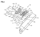
- FIGs. 1 to 4 show an embodiment of the gripper device for conveying a cylindrical body of the invention applied to conveying of a PET bottle.
- FIG. 1 is a schematic perspective view of a part of the device
- FIG. 2 is a sectional view of the part of the device
- FIGs. 3A and 3B are a plan view and a partially enlarged view of the part of the device
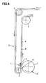
- FIG. 4 is an explanatory view showing a passing section on the conveying chain.
- a gripper device for conveying a cylindrical body (hereinafter referred simply to as "gripper device") 10 is provided, as shown in FIG. 4 , on a conveying chain 4 provided between sprocket wheels 3, 3 of a chain type conveyer apparatus 2 for conveying a bottle B received from a turret 1 of a preceding process such as a process for forming a bottle to a subsequent process such as a process for filling contents in the bottle.
- the gripper device 10 conveys the bottle B along the conveying chain 4 on a straight line (a straight line bending at right angle in the illustrated example).
- This gripper device 10 comprises a fixed frame 11 which is fixed to the conveying chain 4 and is moved integrally with the conveying chain 4.
- the fixed frame 11 is made of a base fixed portion 11a fixed to the conveying chain 4 and a front mounting portion 11b projecting forwardly from the base fixed portion 11a, the portions 11a and 11b being formed integrally with a step being formed between the portions 11a and 11b.
- the fixed frame 11 is fixed to links of the chain 4 by means of bolts and nuts through two mounting holes 11c formed in the base fixed portion 11a.
- a pair of fork-members 12 is mounted on the fixed frame 11 in such a manner that the fork-members 12 can be opened and closed.
- the fork-members 12 are formed with two generally arcuate gripping portions 12a each of which comprises two projecting portions 12b for gripping a coupler B1 formed in the neck portion of the bottle B for screwing a cap thereon and a supporting neck ring B2 and also comprises a recessed portion between the two projecting portions 12b.
- the gripping portions 12a are respectively formed in a manner to oppose each other.
- guiding tapered surfaces 12c In the tip end portions of the the fork-members 12 in front of the gripping portions 12a are formed two guiding tapered surfaces 12c facing each other and continuously to the generally arcuate gripping portions 12a. These guiding tapered surfaces 12c function to cause pushing force of the neck portion of the bottle B to act in a direction to open the fork-members 12, when the neck portion of the bottle B comes into contact with these guiding tapered surfaces 12c
- the length 1 and the angle ⁇ of the guiding tapered surfaces 12c are set in such a manner that shock received in passing of the bottle can be minimized wherebby scratching on the outer surface of the bottle B can be prevented and the fork-members 12 can be opened sufficiently with a minimum force possible.
- the length 1 of the guiding tapered surfaces 12c toward the tip end of the guiding tapered surfaces 12c is set to sufficient length which will avoid abuting of the bottle B to the tip end portion of the guiding tapered surfaces 12c, whereas the angle ⁇ is set to an angle at which the bottle B can contact the guiding tapered surfaces 12c smoothly and impart force to the guiding tapered surfaces 12c to open them.
- the pair of fork-members 12 are fastened to the front mounting portion 11b of the fixed frame 11 by means of bolts and spring washers via fixing pins 12d and presser rings 12e and thereby pivotably mounted on the fixed frame to pivot in opening and closing directions.
- a toothed portion 12f in an arcuate form which is concentric with the fixing pin 12d.
- the toothed portions 12f are in meshing engagement with each other and, by pivoting movement of the pair of fork-members 12 by the same angle, the fork-members 12 are opened or closed uniformly whereby the fork-members 12 can grip the bottle B on both sides and position the bottle B at a desired position such that the central axis of the bottle B aligns with the center of the gripping portions 12a.
- the pair of fork-members 12 comprise, as the energizing means for energizing the gripping portions 12a in closing direction, a compression spring 13 which is provided on the side of the fixing pins 12d of the fork-members 12 opposite to the gripping portions 12a between spring supporting projections 12g formed in the base portion of the fork-members 12 to face each other.
- surface treatment such as plating may be applied to the surface of the fork-members 12 or, alternatively, a buffer material such as synthetic resin or elastic material may be provided on the surface of the fork-members which contacts the bottle B.
- a plurality of the pair of fork-members 12 having the gripping portions 12a are mounted at a predetermined pitch to the conveying chain 4 via the fixed frames 11 to constitute the chain type conveying apparatus 2.
- circular slide plates 5 are fixed to the bottom surface of the conveying chain 4 and the conveying chain 4 moves in sliding movement on a slide rail 7 made of resin and mounted to a frame 6.
- a chain guide 8 of an inverted L-shape is fixed to the frame 6 on either or both sides in the conveying direction for guiding roller links 4a of the conveying chain 4.
- the weight of the fixed frame 11, fork-members 12 and conveying chain 4 including the bottles B can be supported and, in addition to it, movement in a direction other than the conveying direction can also be supported to some extent.
- the fixed frame 11 is pushed through the fork-members 12 whereby the conveying chain 4 is also pushed to be bent between the sprocket wheels 3, 3 and also to move in a horizontal plane in a direction normal to the conveying direction in a gap between the conveying chain 4 and the chain guide 8.
- the fork-members 12 and the fixed frame 11 also tend to incline by pivoting about their horizontal axis.
- a guide member 14 which has a sliding guide surface 14a which contacts, in sliding contact, a rear end surface 11d of the fork-members 12 on the opposite side of the gripping portions 12a which is a side surface of the fixed frame 11 extending in the conveying direction of the fixed frame 11.
- This guide member 14 is fixed to the passing section L for the conveying chain 4.
- This guide member 14 is formed in the upstream side of the conveying direction with a guiding inclined surface 14b which is cut obliquely so as to contact the moving fixed frame 11 smoothly.
- the passing section L in which the guide member 14 is provided is provided as near as possible to the sprocket wheel 3 of the conveying chain 4 so that influence (i.e., stretching of the chain multiplied by the number of links) caused by stretching of the conveying chain 4 can be held at the minimum.
- a liner 11e made of a metal or synthetic resin which is of a relatively small friction coefficient is attached to the rear end surface 11d of the fixed frame 11 by means of a bolt to reduce resistance in the sliding movement.
- the liner 11e can be made integral with the fixed frame 11.
- conveying is made in such a manner that the perpendicular surface of the liner 11e attached to the rear end surface 11d of the fixed frame 11 to which the pair of fork-members 12 are attached contacts the perpendicular sliding guide surface 14a of the guide member 14 and, therefore, the gripping portions 12a of the fork-members 12 can be supported against horizontal force (pushing force) acting in a direction normal to the conveying direction and moment (inclining force) about the horizontal axis of the fork-members 12 applied to the gripping portions 12a whereby the bottle B can be passed to the gripping portions 12a of the fork-members 12 which holds a correct posture and positioning can be made at high accuracy notwithstanding that the fork-members 12 are attached to the conveying chain 4.
- the pair of fork-members 12 comprise, as the energizing means for energizing the gripping portions 12a in closing direction, a compression spring 13 which is provided on the side of the fixing pins 12d of the fork-members 12 opposite to the gripping portions 12a, a cylindrical body such as a neck portion of the bottle B can be automatically gripped firmly simply by pushing the cylindrical body into the gripping portions 12a whereby the cylindrical body such as the bottle can be conveyed while it is gripped by the fork-members 12 and maintains a stable posture.
- the fork-members 12 of the gripper device 10 are energized in closing direction by the energizing means 13 and, when a cylindrical body such as the body B is passed, the fork-members 12 are forced open against the force of the energizing means.
- the fork-members 12 may be closed and opened by a mechanical means such as a cam mechanism.
- a cam may be provided integrally with the guide member 14 so that, in the passing section L, i.e., while the fork-members 12 are in sliding contact with the sliding guide surface 14a of the guide member 14, the fork-members 12 will be opened and closed to perform passing of the cylindrical body.
- the guide member 14 is provided in the straight passing section L in the vicinity of the sprocket wheel 3 of the conveying chain 4, passing can be made with influence by stretching of the conveying chain 4 being held at the minimum.
- the toothed portions 12f are provided about the fixing pins 12d of the fork-members, the toothed portions being in meshing engagement with each other to open and close the gripping portions uniformly and, therefore, the fork-members 12 can be closed and opened uniformly by the toothed portions 12f whereby the cylindrical body can be gripped in the center and accuracy in positioning can be further improved.
- friction powder is produced in some rare cases. Normally, by conveying the bottle B in an inverted state, intrusion of the friction powder into the bottle B can be prevented.
- the nozzle opening portion of the bottle B may be substantially covered by a lid plate which may be provided adjacent to the fork-members 12 so that intrusion of the friction powder into the bottle B will be prevented.
- a vacuum type dust collecting device may be provided to collect the friction powder.
- friction powder collection efficiency will be improved by combining the dust collection device with covering by the chain guide 8.
- the conveying chain 4 should preferably be made of stainless steel to prevent occurrence of stain on the conveying chain 4.
- the side surface of the fixed frame contacts the guide member in sliding contact for guiding.
- plural surfaces such as upper and lower surfaces continuing to the side surface of the fixed frame may be guided by a guide member. It will suffice if at least the side surface of the fixed frame is guided.
- the guide member may be constructed in such a manner that it can be exchanged in a simple manner, e.g., by fixing a liner to the guide member by means of a bolt.
- a part of sprocket wheels may be made movable so that, without changing the entire length of the chain, the conveying distance to a next process may be changed according to the number of bottles to be held by the conveying apparatus.
Abstract
Description
- This invention relates to a gripper device for conveying a cylindrical body and, more particularly, to a device which, in a case where a PET bottle or a preform before forming of a bottle is conveyed by gripping a neck portion of the PET bottle or the preform with a pair of fork-members provided on a conveyer chain, can receive the PET bottle or the preform to be conveyed in a stable manner.
- A bottle such as a PET bottle is generally used as a container of contents such as a drink. In a bottle forming process and in a process for filling contents in a formed bottle, it is necessary to convey a preform or a formed bottle. Usually, a preform or a formed bottle is conveyed by gripping a coupler (a cylindrical portion) for screwing a cap on or a supporting neck ring (a cylindrical portion) provided in a neck portion of the preform or the formed bottle.
- For conveying a preform or a bottle by gripping the neck portion thereof, a gripper having a pair of fork-members which can be opened and closed (see Japanese Patent Application Laid-open Publication No.
11-105116 2003-19744 2006-199309 - In a chain type conveying apparatus which is one of such conveying apparatus using a gripper, a slide table is provided under a conveying chain between sprocket wheels to slide the conveying chain along this slide table. Alternatively, the conveying chain is guided by a chain guide. Weight of a bottle which is gripped by a gripper is supported by such slide table or chain guide whereby the bottle can be conveyed in a stable posture.
- When a bottle is passed to a gripper provided on the conveying chain by pushing the bottle into the opened gripper or by pushing open the gripper by the force of the bottle, the conveying chain is pushed and moved due to deflection or stretching of the conveying chain and, as a result, difficulty arises in accurately positioning the bottle in the gripping portion of the fork-members in passing of the bottle. Besides, the gripper which has received the bottle tends to be inclined resulting in damage to the bottle during conveying or occurrence of inconvenience in a next process. Particularly, in a case where the bottle is conveyed to a filling process after forming of the bottle, it is sometimes carried out to invert the bottle to an upside-down state to prevent intrusion of dust or the like. In this case, center of gravity of the bottle is lifted to a higher position and the bottle tends to fall over resulting in further difficulty in accurate passing of the bottle.
- The present invention has been made in view of the above problems of the prior art. It is an object of the invention to provide a gripper device for conveying a cylindrical body which can pass a bottle or the like in a stable manner without inclination and conveying the bottle by firmly gripping it notwithstanding that the gripper is mounted on a conveying chain.
- For achieving the object of the invention, in the first aspect of the invention, there is provided a gripper device for conveying a cylindrical body comprising:
- a fixed frame which is fixed to a conveying chain and is moved and conveyed integrally with the chain;
- a pair of fork-members each being pivotably mounted on the fixed frame to pivot in opening and closing directions and having gripping portions for gripping a cylindrical body;
- energizing means provided on the side of the pivoting positions of the fork-members opposite to the gripping portions for energizing the gripping portions in closing direction; and
- a guide member provided at least in a passing section of the conveying chain and contacting a side surface of the fixed frame extending in the conveying direction of the fixed frame in sliding contact to maintain the posture of the fork-members.
- In the second aspect of the invention, there is provided a gripper device for conveying a cylindrical body as defined in the first aspect wherein the guide member is provided in a straight passing section in the vicinity of a sprocket wheel of the conveying chain.
- In the third aspect of the invention, there is provided a gripper device for conveying a cylindrical body as defined in the first or second aspect further comprising toothed portions provided in the vicinity of the pivoting positions of the fork-members, said toothed portions being in meshing engagement with each other to open and close the gripping portions uniformly.
- According to the first aspect of the invention, the gripper device for conveying a cylindrical body comprises a fixed frame which is fixed to a conveying chain and is moved and conveyed integrally with the chain, a pair of fork-members each being pivotably mounted on the fixed frame to pivot in opening and closing directions and having gripping portions for gripping a cylindrical body, energizing means provided on the side of the pivoting positions of the fork-members opposite to the gripping portions for energizing the gripping portions in closing direction, and a guide member provided at least in a passing section of the conveying chain and contacting a side surface of the fixed frame extending in the conveying direction of the fixed frame in sliding contact to maintain the posture of the fork-members and, therefore, a cylindrical portion such as a bottle neck portion can be gripped firmly by the energizing means which energizes the gripping portions of the pair of fork-members in closing direction and, by causing the surface of the fixed frame to contact the guide member in at least the passing section of the conveying chain, the posture of the fork-members in passing of a cylindrical body such as a bottle can be stabilized whereby passing can be made by gripping and accurately positioning a predetermined position of the neck portion.
- According to the gripper device for conveying a cylindrical body of the second aspect of the invention, the guide member is provided in a straight passing section in the vicinity of a sprocket wheel of the conveying chain and, therefore, passing can be made by holding influence of stretching of the conveying chain at the minimum.
- According to the gripper device for conveying a cylindrical body of the third aspect of the invention, toothed portions are provided in the vicinity of the pivoting positions of the fork-members, said toothed portions being in meshing engagement with each other to open and close the gripping portions uniformly and, therefore, the fork-members can be closed and opened uniformly by the toothed portions whereby the cylindrical body can be gripped in the center and accuracy in positioning can be further improved.
-
-
FIG. 1 is a schematic perspective view of a part of the gripper device for conveying a cylindrical body of the invention applied to conveying of a PET bottle. -
FIG. 2 is a schematic sectional view of a part of the gripper device for conveying a cylindrical body of the invention applied to conveying of a PET bottle. -
FIGs. 3A and 3B are a plan view and a partially enlarged view of a part of the gripper device for conveying a cylindrical body of the invention applied to conveying of a PET bottle. -
FIG. 4 is an explanatory view showing a passing section of the conveying chain of the gripper device for conveying a cylindrical body of the invention applied to conveying of a PET bottle. - Description will now be made in detail about embodiments of the invention with reference to the accompanying drawings.
-
FIGs. 1 to 4 show an embodiment of the gripper device for conveying a cylindrical body of the invention applied to conveying of a PET bottle.FIG. 1 is a schematic perspective view of a part of the device,FIG. 2 is a sectional view of the part of the device,FIGs. 3A and 3B are a plan view and a partially enlarged view of the part of the device, andFIG. 4 is an explanatory view showing a passing section on the conveying chain. - A gripper device for conveying a cylindrical body (hereinafter referred simply to as "gripper device") 10 is provided, as shown in
FIG. 4 , on aconveying chain 4 provided betweensprocket wheels type conveyer apparatus 2 for conveying a bottle B received from a turret 1 of a preceding process such as a process for forming a bottle to a subsequent process such as a process for filling contents in the bottle. Thegripper device 10 conveys the bottle B along theconveying chain 4 on a straight line (a straight line bending at right angle in the illustrated example). - This
gripper device 10 comprises afixed frame 11 which is fixed to theconveying chain 4 and is moved integrally with theconveying chain 4. As shown inFIGs. 1 and2 , thefixed frame 11 is made of a base fixedportion 11a fixed to theconveying chain 4 and afront mounting portion 11b projecting forwardly from the base fixedportion 11a, theportions portions fixed frame 11 is fixed to links of thechain 4 by means of bolts and nuts through twomounting holes 11c formed in the base fixedportion 11a. - A pair of fork-
members 12 is mounted on thefixed frame 11 in such a manner that the fork-members 12 can be opened and closed. The fork-members 12 are formed with two generally arcuate grippingportions 12a each of which comprises two projectingportions 12b for gripping a coupler B1 formed in the neck portion of the bottle B for screwing a cap thereon and a supporting neck ring B2 and also comprises a recessed portion between the two projectingportions 12b. The grippingportions 12a are respectively formed in a manner to oppose each other. By closing the pair of fork-members 12, the bottle B is gripped by contacting the projectingportions 12b in about half of the outer periphery of the neck portion of the bottle B. In the tip end portions of the the fork-members 12 in front of the grippingportions 12a are formed two guidingtapered surfaces 12c facing each other and continuously to the generally arcuate grippingportions 12a. These guidingtapered surfaces 12c function to cause pushing force of the neck portion of the bottle B to act in a direction to open the fork-members 12, when the neck portion of the bottle B comes into contact with these guidingtapered surfaces 12c - Considering locus of passing of the bottle B which is passed with a certain angle to the center line of the fork-
members 12, as shown inFIG.3A for example, the length 1 and the angle α of the guidingtapered surfaces 12c are set in such a manner that shock received in passing of the bottle can be minimized wherebby scratching on the outer surface of the bottle B can be prevented and the fork-members 12 can be opened sufficiently with a minimum force possible. More specifically, the length 1 of the guidingtapered surfaces 12c toward the tip end of the guidingtapered surfaces 12c is set to sufficient length which will avoid abuting of the bottle B to the tip end portion of the guidingtapered surfaces 12c, whereas the angle α is set to an angle at which the bottle B can contact the guidingtapered surfaces 12c smoothly and impart force to the guidingtapered surfaces 12c to open them. - The pair of fork-
members 12 are fastened to thefront mounting portion 11b of the fixedframe 11 by means of bolts and spring washers viafixing pins 12d and presserrings 12e and thereby pivotably mounted on the fixed frame to pivot in opening and closing directions. In the inner side surface of each of the fork-members 12, there is provided atoothed portion 12f in an arcuate form which is concentric with thefixing pin 12d. Thetoothed portions 12f are in meshing engagement with each other and, by pivoting movement of the pair of fork-members 12 by the same angle, the fork-members 12 are opened or closed uniformly whereby the fork-members 12 can grip the bottle B on both sides and position the bottle B at a desired position such that the central axis of the bottle B aligns with the center of the grippingportions 12a. - The pair of fork-
members 12 comprise, as the energizing means for energizing the grippingportions 12a in closing direction, acompression spring 13 which is provided on the side of thefixing pins 12d of the fork-members 12 opposite to the grippingportions 12a betweenspring supporting projections 12g formed in the base portion of the fork-members 12 to face each other. By this arrangement, when the neck portion of the bottle B is pushed onto the guidingtapered surfaces 12c of the grippingportions 12a, the pushing force of the bottle B acts in the direction to open the fork-members 12 and the bottle B thereby can be mounted in the grippingportions 12a and can be gripped automatically and this gripping state can be held accurately and firmly. - For preventing scratching on the outer surface of the bottle B while it is gripped, surface treatment such as plating may be applied to the surface of the fork-
members 12 or, alternatively, a buffer material such as synthetic resin or elastic material may be provided on the surface of the fork-members which contacts the bottle B. - A plurality of the pair of fork-
members 12 having the grippingportions 12a are mounted at a predetermined pitch to theconveying chain 4 via thefixed frames 11 to constitute the chaintype conveying apparatus 2. For supporting weight of the bottles B which are conveyed and ensuring stable conveying of the bottles B,circular slide plates 5 are fixed to the bottom surface of theconveying chain 4 and theconveying chain 4 moves in sliding movement on aslide rail 7 made of resin and mounted to aframe 6. Achain guide 8 of an inverted L-shape is fixed to theframe 6 on either or both sides in the conveying direction for guidingroller links 4a of theconveying chain 4. By guiding theconveying chain 4 by theslide rail 7 and thechain guide 8, the weight of thefixed frame 11, fork-members 12 andconveying chain 4 including the bottles B can be supported and, in addition to it, movement in a direction other than the conveying direction can also be supported to some extent. - However, when the bottle B is passed to the gripping
portions 12a of the pair of fork-members 12, the fixedframe 11 is pushed through the fork-members 12 whereby theconveying chain 4 is also pushed to be bent between thesprocket wheels conveying chain 4 and thechain guide 8. The fork-members 12 and thefixed frame 11 also tend to incline by pivoting about their horizontal axis. - In the
gripper device 10, aguide member 14 is provided which has asliding guide surface 14a which contacts, in sliding contact, arear end surface 11d of the fork-members 12 on the opposite side of the grippingportions 12a which is a side surface of thefixed frame 11 extending in the conveying direction of thefixed frame 11. Thisguide member 14 is fixed to the passing section L for the conveyingchain 4. - This
guide member 14 is formed in the upstream side of the conveying direction with a guidinginclined surface 14b which is cut obliquely so as to contact the moving fixedframe 11 smoothly. - In this
gripper device 10, the passing section L in which theguide member 14 is provided is provided as near as possible to thesprocket wheel 3 of the conveyingchain 4 so that influence (i.e., stretching of the chain multiplied by the number of links) caused by stretching of the conveyingchain 4 can be held at the minimum. - A
liner 11e made of a metal or synthetic resin which is of a relatively small friction coefficient is attached to therear end surface 11d of the fixedframe 11 by means of a bolt to reduce resistance in the sliding movement. - Alternatively, by properly cutting the
rear send surface 11d to reduce friction coefficient, theliner 11e can be made integral with the fixedframe 11. - In the
gripper device 10 constructed in the above described manner, conveying is made in such a manner that the perpendicular surface of theliner 11e attached to therear end surface 11d of the fixedframe 11 to which the pair of fork-members 12 are attached contacts the perpendicular slidingguide surface 14a of theguide member 14 and, therefore, the grippingportions 12a of the fork-members 12 can be supported against horizontal force (pushing force) acting in a direction normal to the conveying direction and moment (inclining force) about the horizontal axis of the fork-members 12 applied to thegripping portions 12a whereby the bottle B can be passed to thegripping portions 12a of the fork-members 12 which holds a correct posture and positioning can be made at high accuracy notwithstanding that the fork-members 12 are attached to the conveyingchain 4. - Further, according to the
gripper device 10, the pair of fork-members 12 comprise, as the energizing means for energizing thegripping portions 12a in closing direction, acompression spring 13 which is provided on the side of the fixing pins 12d of the fork-members 12 opposite to thegripping portions 12a, a cylindrical body such as a neck portion of the bottle B can be automatically gripped firmly simply by pushing the cylindrical body into thegripping portions 12a whereby the cylindrical body such as the bottle can be conveyed while it is gripped by the fork-members 12 and maintains a stable posture. - In the above described structure, the fork-
members 12 of thegripper device 10 are energized in closing direction by the energizing means 13 and, when a cylindrical body such as the body B is passed, the fork-members 12 are forced open against the force of the energizing means. Alternatively, instead of the above opening structure, the fork-members 12 may be closed and opened by a mechanical means such as a cam mechanism. In this case, a cam may be provided integrally with theguide member 14 so that, in the passing section L, i.e., while the fork-members 12 are in sliding contact with the slidingguide surface 14a of theguide member 14, the fork-members 12 will be opened and closed to perform passing of the cylindrical body. - According to the
gripper device 10, since theguide member 14 is provided in the straight passing section L in the vicinity of thesprocket wheel 3 of the conveyingchain 4, passing can be made with influence by stretching of the conveyingchain 4 being held at the minimum. - Further, according to this
gripper device 10, thetoothed portions 12f are provided about the fixing pins 12d of the fork-members, the toothed portions being in meshing engagement with each other to open and close the gripping portions uniformly and, therefore, the fork-members 12 can be closed and opened uniformly by thetoothed portions 12f whereby the cylindrical body can be gripped in the center and accuracy in positioning can be further improved. - In the
gripper device 10 in which theslide plates 5 of the conveyingchain 4 slide over theslide rail 7, friction powder is produced in some rare cases. Normally, by conveying the bottle B in an inverted state, intrusion of the friction powder into the bottle B can be prevented. - In a case, however, where the conveying
chain 4 is moved at a high speed or the chaintype conveying apparatus 2 is installed in some special environment, production of the friction powder may increase. - In this case, scattering of the friction powder can be prevented by providing the
chain guide 8 for guiding the conveyingchain 4 on both sides of the conveyingchain 4 over substantially all length of the conveyingchain 4. Alternatively, the nozzle opening portion of the bottle B may be substantially covered by a lid plate which may be provided adjacent to the fork-members 12 so that intrusion of the friction powder into the bottle B will be prevented. - Alternatively further, a vacuum type dust collecting device may be provided to collect the friction powder. In this case, friction powder collection efficiency will be improved by combining the dust collection device with covering by the
chain guide 8. - It is also possible to provide a pan on the floor of the chain
type conveying apparatus 2 and washing the chaintype conveying apparatus 2 by scattering water on theapparatus 2 by means of a shower to remove the friction powder. In this case, the conveyingchain 4 should preferably be made of stainless steel to prevent occurrence of stain on the conveyingchain 4. - In the above described embodiment, the side surface of the fixed frame contacts the guide member in sliding contact for guiding. Alternatively, plural surfaces such as upper and lower surfaces continuing to the side surface of the fixed frame may be guided by a guide member. It will suffice if at least the side surface of the fixed frame is guided.
- Instead of constituting the guide member with synthetic resin or metal, the guide member may be constructed in such a manner that it can be exchanged in a simple manner, e.g., by fixing a liner to the guide member by means of a bolt.
- As to the chain conveying apparatus, various modifications may be made such, for example, that a part of sprocket wheels may be made movable so that, without changing the entire length of the chain, the conveying distance to a next process may be changed according to the number of bottles to be held by the conveying apparatus.
Claims (3)
- A gripper device for conveying a cylindrical body comprising:a fixed frame which is fixed to a conveying chain and is moved and conveyed integrally with the chain;a pair of fork-members each being pivotably mounted on the fixed frame to pivot in opening and closing directions and having gripping portions for gripping a cylindrical body;energizing means provided on the side of the pivoting positions of the fork-members opposite to the gripping portions for energizing the gripping portions in closing direction; anda guide member provided at least in a passing section of the conveying chain and contacting a side surface of the fixed frame extending in the conveying direction of the fixed frame in sliding contact to maintain the posture of the fork-members.
- A gripper device for conveying a cylindrical body as defined in claim 1 wherein the guide member is provided in a straight passing section in the vicinity of a sprocket wheel of the conveying chain.
- A gripper device for conveying a cylindrical body as defined in claim 1 or 2 further comprising toothed portions provided in the vicinity of the pivoting positions of the fork-members, said toothed portions being in meshing engagement with each other to open and close the gripping portions uniformly.
Applications Claiming Priority (2)
| Application Number | Priority Date | Filing Date | Title |
|---|---|---|---|
| JP2007243870A JP5282239B2 (en) | 2007-09-20 | 2007-09-20 | Gripper device for cylindrical transfer |
| PCT/JP2008/066414 WO2009038014A1 (en) | 2007-09-20 | 2008-09-11 | Gripper device for conveying circular tube body |
Publications (3)
| Publication Number | Publication Date |
|---|---|
| EP2202183A1 true EP2202183A1 (en) | 2010-06-30 |
| EP2202183A4 EP2202183A4 (en) | 2013-05-29 |
| EP2202183B1 EP2202183B1 (en) | 2014-11-05 |
Family
ID=40467831
Family Applications (1)
| Application Number | Title | Priority Date | Filing Date |
|---|---|---|---|
| EP08832673.1A Active EP2202183B1 (en) | 2007-09-20 | 2008-09-11 | Gripper device for conveying circular tube body |
Country Status (5)
| Country | Link |
|---|---|
| US (1) | US20100282574A1 (en) |
| EP (1) | EP2202183B1 (en) |
| JP (1) | JP5282239B2 (en) |
| CN (1) | CN101801822B (en) |
| WO (1) | WO2009038014A1 (en) |
Cited By (3)
| Publication number | Priority date | Publication date | Assignee | Title |
|---|---|---|---|---|
| WO2012069109A1 (en) * | 2010-11-25 | 2012-05-31 | Khs Gmbh | Pet bottle gripping device |
| FR3018793A1 (en) * | 2014-03-24 | 2015-09-25 | Cermex Const Etudes Et Rech S De Materiels Pour L Emballage D Expedition | METHOD OF COLLECTING AT LEAST ONE PRODUCT AND INSTALLATION ENABLING THE PROCESS |
| WO2017158553A1 (en) * | 2016-03-17 | 2017-09-21 | I.M.A. Industria Macchine Automatiche S.P.A In Sigla Ima S.P.A. | Assembly for feeding/picking up containers for washing machines and washing machine |
Families Citing this family (7)
| Publication number | Priority date | Publication date | Assignee | Title |
|---|---|---|---|---|
| DE202005002924U1 (en) * | 2005-02-23 | 2006-03-30 | Krones Ag | Clip gripper for a vascular transport system |
| FR2949768A1 (en) * | 2009-09-07 | 2011-03-11 | Coremap | Gripper conveyor for conveying objects e.g. flasks, has movable grippers comprising movable jaws that are movable with respect to fixed jaws, where fixed jaws include positioning notches co-operating with objects gripped by grippers |
| ES2562930T3 (en) * | 2009-09-29 | 2016-03-09 | Sluis Cigar Machinery B.V. | Transfer device intended to transfer an item |
| WO2014209116A1 (en) * | 2013-06-24 | 2014-12-31 | Sluis Cigar Machinery B.V. | Gripper for holding an item |
| US10017368B2 (en) * | 2014-11-25 | 2018-07-10 | The Wine Group, Inc. | Cap gripper |
| CN107214098B (en) * | 2017-05-26 | 2023-11-24 | 惠州市三协精密有限公司 | Magnet feeding turntable mechanism and magnet automatic feeding detection equipment thereof |
| CN115465491B (en) * | 2022-08-31 | 2023-07-18 | 长春电子科技学院 | Positioner for ceramic packaging equipment |
Citations (4)
| Publication number | Priority date | Publication date | Assignee | Title |
|---|---|---|---|---|
| WO2003078285A1 (en) * | 2002-03-18 | 2003-09-25 | S.I.P.A. Societa' Industrializzazione Progettazione E Automazione S.P.A. | A gripping device for bottles and similar |
| DE10348431A1 (en) * | 2003-06-12 | 2005-01-05 | Krones Ag | Palletizing device for articles e.g. empty plastic bottles, has converter that feeds carriageway and buffer alternatively with articles and pallet loader that picks articles alternatively from carriageway and buffer |
| US20050103604A1 (en) * | 2003-11-13 | 2005-05-19 | Hartness International, Inc. | Gripper conveyor with clear conveying path and related conveyor link |
| WO2012035645A1 (en) * | 2010-09-17 | 2012-03-22 | 東洋製罐株式会社 | Gripper carrying device |
Family Cites Families (18)
| Publication number | Priority date | Publication date | Assignee | Title |
|---|---|---|---|---|
| JPS4522824Y1 (en) * | 1966-02-11 | 1970-09-09 | ||
| JPS5436469Y2 (en) * | 1975-05-10 | 1979-11-02 | ||
| US4055943A (en) * | 1976-06-09 | 1977-11-01 | Abc Packaging Machine Corporation | Bottle loading machine |
| US4172514A (en) * | 1977-02-07 | 1979-10-30 | Giddings & Lewis, Inc. | High speed continuous assembly machine |
| JPS5494187A (en) * | 1978-01-10 | 1979-07-25 | Kato Yoshihiko | Method of cutting paper cylinder |
| JPS5558510U (en) * | 1978-10-18 | 1980-04-21 | ||
| JPS56161217A (en) * | 1980-05-15 | 1981-12-11 | Y O Plant Kk | Taking-out device for conical article |
| JPS5748512A (en) * | 1980-09-03 | 1982-03-19 | Dengensha Mfg Co Ltd | Chain conveyor |
| JPS63210040A (en) * | 1987-02-26 | 1988-08-31 | Toyo Glass Kk | Device for transferring glass bottle |
| US5353908A (en) * | 1992-02-12 | 1994-10-11 | Shibuya Kogyo Company, Ltd. | Suspended conveyance apparatus |
| DE59601245D1 (en) * | 1995-05-13 | 1999-03-18 | Hermann Kronseder | Transport star for vessels |
| JP3365276B2 (en) | 1997-10-03 | 2003-01-08 | 東洋製罐株式会社 | Gripper device for holding hollow bodies |
| JPH11314752A (en) * | 1998-04-30 | 1999-11-16 | Mitsubishi Heavy Ind Ltd | Bottle conveyor system |
| JP3705244B2 (en) | 2002-06-17 | 2005-10-12 | 東洋製罐株式会社 | Gripper device for hollow body gripping |
| EP1673295B1 (en) * | 2003-10-14 | 2008-03-12 | Krones AG | Palletizing device |
| US7185753B2 (en) * | 2004-09-28 | 2007-03-06 | Hartness International, Inc. | Shuttle conveyor |
| JP2006199309A (en) | 2005-01-18 | 2006-08-03 | Toyo Seikan Kaisha Ltd | Gripper device for gripping coupler section |
| JP4666584B2 (en) * | 2005-02-04 | 2011-04-06 | 花王株式会社 | Container transfer device |
-
2007
- 2007-09-20 JP JP2007243870A patent/JP5282239B2/en active Active
-
2008
- 2008-09-11 WO PCT/JP2008/066414 patent/WO2009038014A1/en active Application Filing
- 2008-09-11 EP EP08832673.1A patent/EP2202183B1/en active Active
- 2008-09-11 US US12/733,734 patent/US20100282574A1/en not_active Abandoned
- 2008-09-11 CN CN200880107839.8A patent/CN101801822B/en active Active
Patent Citations (4)
| Publication number | Priority date | Publication date | Assignee | Title |
|---|---|---|---|---|
| WO2003078285A1 (en) * | 2002-03-18 | 2003-09-25 | S.I.P.A. Societa' Industrializzazione Progettazione E Automazione S.P.A. | A gripping device for bottles and similar |
| DE10348431A1 (en) * | 2003-06-12 | 2005-01-05 | Krones Ag | Palletizing device for articles e.g. empty plastic bottles, has converter that feeds carriageway and buffer alternatively with articles and pallet loader that picks articles alternatively from carriageway and buffer |
| US20050103604A1 (en) * | 2003-11-13 | 2005-05-19 | Hartness International, Inc. | Gripper conveyor with clear conveying path and related conveyor link |
| WO2012035645A1 (en) * | 2010-09-17 | 2012-03-22 | 東洋製罐株式会社 | Gripper carrying device |
Non-Patent Citations (1)
| Title |
|---|
| See also references of WO2009038014A1 * |
Cited By (7)
| Publication number | Priority date | Publication date | Assignee | Title |
|---|---|---|---|---|
| WO2012069109A1 (en) * | 2010-11-25 | 2012-05-31 | Khs Gmbh | Pet bottle gripping device |
| US8894114B2 (en) | 2010-11-25 | 2014-11-25 | Khs Gmbh | PET bottle gripping device |
| FR3018793A1 (en) * | 2014-03-24 | 2015-09-25 | Cermex Const Etudes Et Rech S De Materiels Pour L Emballage D Expedition | METHOD OF COLLECTING AT LEAST ONE PRODUCT AND INSTALLATION ENABLING THE PROCESS |
| WO2015145039A1 (en) * | 2014-03-24 | 2015-10-01 | C.E.R.M.E.X. Constructions Etudes Et Recherches De Materiels Pour L'emballage D'expedition | Method for collecting at least one product, and equipment ensuring implementation of the method |
| US9975655B2 (en) | 2014-03-24 | 2018-05-22 | C.E.R.M.E.X. Constructions Etudes Et Recherches De Materiels Pour L'emballage D'expedition | Method for collecting at least one product, and equipment ensuring implementation of the method |
| WO2017158553A1 (en) * | 2016-03-17 | 2017-09-21 | I.M.A. Industria Macchine Automatiche S.P.A In Sigla Ima S.P.A. | Assembly for feeding/picking up containers for washing machines and washing machine |
| US11198162B2 (en) | 2016-03-17 | 2021-12-14 | I.M.A. Industria Macchine Automatiche S.P.A In Sigla Ima S.P.A. | Assembly for feeding/picking up containers for washing machines and washing machine |
Also Published As
| Publication number | Publication date |
|---|---|
| EP2202183A4 (en) | 2013-05-29 |
| EP2202183B1 (en) | 2014-11-05 |
| CN101801822B (en) | 2015-07-29 |
| WO2009038014A1 (en) | 2009-03-26 |
| JP5282239B2 (en) | 2013-09-04 |
| US20100282574A1 (en) | 2010-11-11 |
| CN101801822A (en) | 2010-08-11 |
| JP2009073617A (en) | 2009-04-09 |
Similar Documents
| Publication | Publication Date | Title |
|---|---|---|
| EP2202183B1 (en) | Gripper device for conveying circular tube body | |
| US8474601B2 (en) | Container transfer device having a transfer guiding member | |
| US5415322A (en) | Machine for automatically positioning and aligning containers | |
| US20020144880A1 (en) | Bag conveying apparatus and a gripper endless chain used in a bag filling packaging machine | |
| FI108021B (en) | Endless conveyor for bulk goods with separate transport elements | |
| US20110064555A1 (en) | Gripper unit for supporting and transporting articles | |
| EP0875470A1 (en) | Conveying chain apparatus | |
| EP1426313A1 (en) | A transfer unit for containers | |
| CA2259121A1 (en) | Method for the suspended conveying of containers and device for carrying out said method | |
| JP2021172523A (en) | Plant for processing containers | |
| JP2007511444A (en) | Conveyor with movable gripping member and associated conveyor link | |
| NL9100405A (en) | APPARATUS FOR TRANSPORTING OBJECTS, IN PARTICULAR FOR AUTOMATIC PACKAGING INSTALLATIONS. | |
| EP1685043A1 (en) | Conveyor with movable gripper and related conveyor link | |
| EP0017470B1 (en) | Apparatus for moving and orienting bottles | |
| US20040255561A1 (en) | Envelope and insert transport and insertion machine | |
| JPH05278852A (en) | Conveying device | |
| US5160019A (en) | Carrier for articles such as eggs and conveying apparatus comprising such a carrier | |
| EP1306307B1 (en) | Cover feeder | |
| WO2005049455A1 (en) | Gripper conveyor with clear conveying path and related conveyor link | |
| US4070854A (en) | Apparatus for removing bottle caps | |
| US10278402B2 (en) | Apparatus for transporting elongate sausages which have a curvature | |
| EP1367011A1 (en) | A conveying apparatus for spouts or bags with spouts | |
| KR20010113754A (en) | Device for coating bottles and bodies for transporting bottles | |
| US6283276B1 (en) | Overhead pusher finger guide system | |
| KR870000859B1 (en) | Slide-fastener discharging apparatus |
Legal Events
| Date | Code | Title | Description |
|---|---|---|---|
| PUAI | Public reference made under article 153(3) epc to a published international application that has entered the european phase |
Free format text: ORIGINAL CODE: 0009012 |
|
| 17P | Request for examination filed |
Effective date: 20100401 |
|
| AK | Designated contracting states |
Kind code of ref document: A1 Designated state(s): AT BE BG CH CY CZ DE DK EE ES FI FR GB GR HR HU IE IS IT LI LT LU LV MC MT NL NO PL PT RO SE SI SK TR |
|
| AX | Request for extension of the european patent |
Extension state: AL BA MK RS |
|
| DAX | Request for extension of the european patent (deleted) | ||
| RAP1 | Party data changed (applicant data changed or rights of an application transferred) |
Owner name: TOYO SEIKAN KAISHA, LTD. |
|
| A4 | Supplementary search report drawn up and despatched |
Effective date: 20130425 |
|
| RIC1 | Information provided on ipc code assigned before grant |
Ipc: B65G 47/86 20060101ALI20130419BHEP Ipc: B65G 47/90 20060101AFI20130419BHEP |
|
| GRAP | Despatch of communication of intention to grant a patent |
Free format text: ORIGINAL CODE: EPIDOSNIGR1 |
|
| RIC1 | Information provided on ipc code assigned before grant |
Ipc: B65G 17/32 20060101ALI20140523BHEP Ipc: B65G 47/90 20060101AFI20140523BHEP Ipc: B65G 47/86 20060101ALI20140523BHEP |
|
| INTG | Intention to grant announced |
Effective date: 20140611 |
|
| GRAS | Grant fee paid |
Free format text: ORIGINAL CODE: EPIDOSNIGR3 |
|
| GRAA | (expected) grant |
Free format text: ORIGINAL CODE: 0009210 |
|
| AK | Designated contracting states |
Kind code of ref document: B1 Designated state(s): AT BE BG CH CY CZ DE DK EE ES FI FR GB GR HR HU IE IS IT LI LT LU LV MC MT NL NO PL PT RO SE SI SK TR |
|
| REG | Reference to a national code |
Ref country code: GB Ref legal event code: FG4D |
|
| REG | Reference to a national code |
Ref country code: CH Ref legal event code: EP |
|
| REG | Reference to a national code |
Ref country code: AT Ref legal event code: REF Ref document number: 694489 Country of ref document: AT Kind code of ref document: T Effective date: 20141115 |
|
| REG | Reference to a national code |
Ref country code: IE Ref legal event code: FG4D |
|
| REG | Reference to a national code |
Ref country code: DE Ref legal event code: R096 Ref document number: 602008035239 Country of ref document: DE Effective date: 20141218 |
|
| REG | Reference to a national code |
Ref country code: AT Ref legal event code: MK05 Ref document number: 694489 Country of ref document: AT Kind code of ref document: T Effective date: 20141105 |
|
| REG | Reference to a national code |
Ref country code: NL Ref legal event code: VDEP Effective date: 20141105 |
|
| REG | Reference to a national code |
Ref country code: LT Ref legal event code: MG4D |
|
| PG25 | Lapsed in a contracting state [announced via postgrant information from national office to epo] |
Ref country code: FI Free format text: LAPSE BECAUSE OF FAILURE TO SUBMIT A TRANSLATION OF THE DESCRIPTION OR TO PAY THE FEE WITHIN THE PRESCRIBED TIME-LIMIT Effective date: 20141105 Ref country code: IS Free format text: LAPSE BECAUSE OF FAILURE TO SUBMIT A TRANSLATION OF THE DESCRIPTION OR TO PAY THE FEE WITHIN THE PRESCRIBED TIME-LIMIT Effective date: 20150305 Ref country code: ES Free format text: LAPSE BECAUSE OF FAILURE TO SUBMIT A TRANSLATION OF THE DESCRIPTION OR TO PAY THE FEE WITHIN THE PRESCRIBED TIME-LIMIT Effective date: 20141105 Ref country code: NO Free format text: LAPSE BECAUSE OF FAILURE TO SUBMIT A TRANSLATION OF THE DESCRIPTION OR TO PAY THE FEE WITHIN THE PRESCRIBED TIME-LIMIT Effective date: 20150205 Ref country code: LT Free format text: LAPSE BECAUSE OF FAILURE TO SUBMIT A TRANSLATION OF THE DESCRIPTION OR TO PAY THE FEE WITHIN THE PRESCRIBED TIME-LIMIT Effective date: 20141105 Ref country code: PT Free format text: LAPSE BECAUSE OF FAILURE TO SUBMIT A TRANSLATION OF THE DESCRIPTION OR TO PAY THE FEE WITHIN THE PRESCRIBED TIME-LIMIT Effective date: 20150305 Ref country code: NL Free format text: LAPSE BECAUSE OF FAILURE TO SUBMIT A TRANSLATION OF THE DESCRIPTION OR TO PAY THE FEE WITHIN THE PRESCRIBED TIME-LIMIT Effective date: 20141105 |
|
| PG25 | Lapsed in a contracting state [announced via postgrant information from national office to epo] |
Ref country code: AT Free format text: LAPSE BECAUSE OF FAILURE TO SUBMIT A TRANSLATION OF THE DESCRIPTION OR TO PAY THE FEE WITHIN THE PRESCRIBED TIME-LIMIT Effective date: 20141105 Ref country code: CY Free format text: LAPSE BECAUSE OF FAILURE TO SUBMIT A TRANSLATION OF THE DESCRIPTION OR TO PAY THE FEE WITHIN THE PRESCRIBED TIME-LIMIT Effective date: 20141105 Ref country code: HR Free format text: LAPSE BECAUSE OF FAILURE TO SUBMIT A TRANSLATION OF THE DESCRIPTION OR TO PAY THE FEE WITHIN THE PRESCRIBED TIME-LIMIT Effective date: 20141105 Ref country code: GR Free format text: LAPSE BECAUSE OF FAILURE TO SUBMIT A TRANSLATION OF THE DESCRIPTION OR TO PAY THE FEE WITHIN THE PRESCRIBED TIME-LIMIT Effective date: 20150206 Ref country code: LV Free format text: LAPSE BECAUSE OF FAILURE TO SUBMIT A TRANSLATION OF THE DESCRIPTION OR TO PAY THE FEE WITHIN THE PRESCRIBED TIME-LIMIT Effective date: 20141105 Ref country code: PL Free format text: LAPSE BECAUSE OF FAILURE TO SUBMIT A TRANSLATION OF THE DESCRIPTION OR TO PAY THE FEE WITHIN THE PRESCRIBED TIME-LIMIT Effective date: 20141105 Ref country code: SE Free format text: LAPSE BECAUSE OF FAILURE TO SUBMIT A TRANSLATION OF THE DESCRIPTION OR TO PAY THE FEE WITHIN THE PRESCRIBED TIME-LIMIT Effective date: 20141105 |
|
| PG25 | Lapsed in a contracting state [announced via postgrant information from national office to epo] |
Ref country code: RO Free format text: LAPSE BECAUSE OF FAILURE TO SUBMIT A TRANSLATION OF THE DESCRIPTION OR TO PAY THE FEE WITHIN THE PRESCRIBED TIME-LIMIT Effective date: 20141105 Ref country code: CZ Free format text: LAPSE BECAUSE OF FAILURE TO SUBMIT A TRANSLATION OF THE DESCRIPTION OR TO PAY THE FEE WITHIN THE PRESCRIBED TIME-LIMIT Effective date: 20141105 Ref country code: EE Free format text: LAPSE BECAUSE OF FAILURE TO SUBMIT A TRANSLATION OF THE DESCRIPTION OR TO PAY THE FEE WITHIN THE PRESCRIBED TIME-LIMIT Effective date: 20141105 Ref country code: DK Free format text: LAPSE BECAUSE OF FAILURE TO SUBMIT A TRANSLATION OF THE DESCRIPTION OR TO PAY THE FEE WITHIN THE PRESCRIBED TIME-LIMIT Effective date: 20141105 Ref country code: SK Free format text: LAPSE BECAUSE OF FAILURE TO SUBMIT A TRANSLATION OF THE DESCRIPTION OR TO PAY THE FEE WITHIN THE PRESCRIBED TIME-LIMIT Effective date: 20141105 |
|
| REG | Reference to a national code |
Ref country code: DE Ref legal event code: R097 Ref document number: 602008035239 Country of ref document: DE |
|
| PLBE | No opposition filed within time limit |
Free format text: ORIGINAL CODE: 0009261 |
|
| STAA | Information on the status of an ep patent application or granted ep patent |
Free format text: STATUS: NO OPPOSITION FILED WITHIN TIME LIMIT |
|
| REG | Reference to a national code |
Ref country code: FR Ref legal event code: PLFP Year of fee payment: 8 |
|
| 26N | No opposition filed |
Effective date: 20150806 |
|
| PG25 | Lapsed in a contracting state [announced via postgrant information from national office to epo] |
Ref country code: SI Free format text: LAPSE BECAUSE OF FAILURE TO SUBMIT A TRANSLATION OF THE DESCRIPTION OR TO PAY THE FEE WITHIN THE PRESCRIBED TIME-LIMIT Effective date: 20141105 |
|
| REG | Reference to a national code |
Ref country code: DE Ref legal event code: R082 Ref document number: 602008035239 Country of ref document: DE Representative=s name: MUELLER SCHUPFNER & PARTNER PATENT- UND RECHTS, DE Ref country code: DE Ref legal event code: R081 Ref document number: 602008035239 Country of ref document: DE Owner name: TOYO SEIKAN GROUP HOLDINGS, LTD., JP Free format text: FORMER OWNER: TOYO SEIKAN KAISHA, LTD., TOKIO/TOKYO, JP |
|
| PG25 | Lapsed in a contracting state [announced via postgrant information from national office to epo] |
Ref country code: MC Free format text: LAPSE BECAUSE OF FAILURE TO SUBMIT A TRANSLATION OF THE DESCRIPTION OR TO PAY THE FEE WITHIN THE PRESCRIBED TIME-LIMIT Effective date: 20141105 Ref country code: LU Free format text: LAPSE BECAUSE OF FAILURE TO SUBMIT A TRANSLATION OF THE DESCRIPTION OR TO PAY THE FEE WITHIN THE PRESCRIBED TIME-LIMIT Effective date: 20150911 |
|
| REG | Reference to a national code |
Ref country code: CH Ref legal event code: PL |
|
| GBPC | Gb: european patent ceased through non-payment of renewal fee |
Effective date: 20150911 |
|
| REG | Reference to a national code |
Ref country code: FR Ref legal event code: CD Owner name: TOYO SEIKAN GROUP HOLDINGS, LTD., JP Effective date: 20160425 |
|
| REG | Reference to a national code |
Ref country code: IE Ref legal event code: MM4A |
|
| PG25 | Lapsed in a contracting state [announced via postgrant information from national office to epo] |
Ref country code: LI Free format text: LAPSE BECAUSE OF NON-PAYMENT OF DUE FEES Effective date: 20150930 Ref country code: IE Free format text: LAPSE BECAUSE OF NON-PAYMENT OF DUE FEES Effective date: 20150911 Ref country code: GB Free format text: LAPSE BECAUSE OF NON-PAYMENT OF DUE FEES Effective date: 20150911 Ref country code: CH Free format text: LAPSE BECAUSE OF NON-PAYMENT OF DUE FEES Effective date: 20150930 |
|
| REG | Reference to a national code |
Ref country code: FR Ref legal event code: PLFP Year of fee payment: 9 |
|
| PG25 | Lapsed in a contracting state [announced via postgrant information from national office to epo] |
Ref country code: MT Free format text: LAPSE BECAUSE OF FAILURE TO SUBMIT A TRANSLATION OF THE DESCRIPTION OR TO PAY THE FEE WITHIN THE PRESCRIBED TIME-LIMIT Effective date: 20141105 |
|
| PG25 | Lapsed in a contracting state [announced via postgrant information from national office to epo] |
Ref country code: HU Free format text: LAPSE BECAUSE OF FAILURE TO SUBMIT A TRANSLATION OF THE DESCRIPTION OR TO PAY THE FEE WITHIN THE PRESCRIBED TIME-LIMIT; INVALID AB INITIO Effective date: 20080911 Ref country code: BG Free format text: LAPSE BECAUSE OF FAILURE TO SUBMIT A TRANSLATION OF THE DESCRIPTION OR TO PAY THE FEE WITHIN THE PRESCRIBED TIME-LIMIT Effective date: 20141105 |
|
| PG25 | Lapsed in a contracting state [announced via postgrant information from national office to epo] |
Ref country code: TR Free format text: LAPSE BECAUSE OF FAILURE TO SUBMIT A TRANSLATION OF THE DESCRIPTION OR TO PAY THE FEE WITHIN THE PRESCRIBED TIME-LIMIT Effective date: 20141105 |
|
| REG | Reference to a national code |
Ref country code: FR Ref legal event code: PLFP Year of fee payment: 10 |
|
| PG25 | Lapsed in a contracting state [announced via postgrant information from national office to epo] |
Ref country code: BE Free format text: LAPSE BECAUSE OF FAILURE TO SUBMIT A TRANSLATION OF THE DESCRIPTION OR TO PAY THE FEE WITHIN THE PRESCRIBED TIME-LIMIT Effective date: 20141105 |
|
| REG | Reference to a national code |
Ref country code: FR Ref legal event code: PLFP Year of fee payment: 11 |
|
| PGFP | Annual fee paid to national office [announced via postgrant information from national office to epo] |
Ref country code: FR Payment date: 20230928 Year of fee payment: 16 Ref country code: DE Payment date: 20230920 Year of fee payment: 16 |
|
| PGFP | Annual fee paid to national office [announced via postgrant information from national office to epo] |
Ref country code: IT Payment date: 20230927 Year of fee payment: 16 |