EP2202032A2 - Grinding wheel with non-stick coating - Google Patents
Grinding wheel with non-stick coating Download PDFInfo
- Publication number
- EP2202032A2 EP2202032A2 EP09177709A EP09177709A EP2202032A2 EP 2202032 A2 EP2202032 A2 EP 2202032A2 EP 09177709 A EP09177709 A EP 09177709A EP 09177709 A EP09177709 A EP 09177709A EP 2202032 A2 EP2202032 A2 EP 2202032A2
- Authority
- EP
- European Patent Office
- Prior art keywords
- core
- grinding wheel
- end surfaces
- grinding
- coating film
- Prior art date
- Legal status (The legal status is an assumption and is not a legal conclusion. Google has not performed a legal analysis and makes no representation as to the accuracy of the status listed.)
- Granted
Links
- 238000000227 grinding Methods 0.000 title claims abstract description 125
- 238000000576 coating method Methods 0.000 title claims abstract description 58
- 239000011248 coating agent Substances 0.000 title claims abstract description 57
- 229920002313 fluoropolymer Polymers 0.000 claims abstract description 34
- ZZUFCTLCJUWOSV-UHFFFAOYSA-N furosemide Chemical group C1=C(Cl)C(S(=O)(=O)N)=CC(C(O)=O)=C1NCC1=CC=CO1 ZZUFCTLCJUWOSV-UHFFFAOYSA-N 0.000 claims description 25
- 238000000034 method Methods 0.000 claims description 15
- 238000009434 installation Methods 0.000 claims description 13
- 238000007747 plating Methods 0.000 claims description 9
- 229910019142 PO4 Inorganic materials 0.000 claims description 7
- NBIIXXVUZAFLBC-UHFFFAOYSA-K phosphate Chemical compound [O-]P([O-])([O-])=O NBIIXXVUZAFLBC-UHFFFAOYSA-K 0.000 claims description 7
- 239000010452 phosphate Substances 0.000 claims description 7
- 238000006243 chemical reaction Methods 0.000 claims description 4
- 239000002826 coolant Substances 0.000 description 18
- 239000010410 layer Substances 0.000 description 10
- 229910000831 Steel Inorganic materials 0.000 description 6
- 239000010959 steel Substances 0.000 description 6
- XEEYBQQBJWHFJM-UHFFFAOYSA-N Iron Chemical compound [Fe] XEEYBQQBJWHFJM-UHFFFAOYSA-N 0.000 description 5
- 238000003780 insertion Methods 0.000 description 5
- 230000037431 insertion Effects 0.000 description 5
- 239000000463 material Substances 0.000 description 5
- 238000011282 treatment Methods 0.000 description 5
- -1 alkyl vinyl ether Chemical compound 0.000 description 4
- 230000000694 effects Effects 0.000 description 3
- 229910052742 iron Inorganic materials 0.000 description 3
- 238000004519 manufacturing process Methods 0.000 description 3
- 229920001343 polytetrafluoroethylene Polymers 0.000 description 3
- 239000004810 polytetrafluoroethylene Substances 0.000 description 3
- 229910000838 Al alloy Inorganic materials 0.000 description 2
- 229920001780 ECTFE Polymers 0.000 description 2
- PXHVJJICTQNCMI-UHFFFAOYSA-N Nickel Chemical compound [Ni] PXHVJJICTQNCMI-UHFFFAOYSA-N 0.000 description 2
- 238000005299 abrasion Methods 0.000 description 2
- 239000012790 adhesive layer Substances 0.000 description 2
- 238000003287 bathing Methods 0.000 description 2
- 230000015556 catabolic process Effects 0.000 description 2
- 229920001577 copolymer Polymers 0.000 description 2
- 238000005260 corrosion Methods 0.000 description 2
- 230000007797 corrosion Effects 0.000 description 2
- 238000006731 degradation reaction Methods 0.000 description 2
- 229910003460 diamond Inorganic materials 0.000 description 2
- 239000010432 diamond Substances 0.000 description 2
- 229910052751 metal Inorganic materials 0.000 description 2
- 239000002184 metal Substances 0.000 description 2
- 239000003595 mist Substances 0.000 description 2
- 230000002093 peripheral effect Effects 0.000 description 2
- 229920002493 poly(chlorotrifluoroethylene) Polymers 0.000 description 2
- 239000005023 polychlorotrifluoroethylene (PCTFE) polymer Substances 0.000 description 2
- BFKJFAAPBSQJPD-UHFFFAOYSA-N tetrafluoroethene Chemical group FC(F)=C(F)F BFKJFAAPBSQJPD-UHFFFAOYSA-N 0.000 description 2
- XLYOFNOQVPJJNP-UHFFFAOYSA-N water Substances O XLYOFNOQVPJJNP-UHFFFAOYSA-N 0.000 description 2
- KRHYYFGTRYWZRS-UHFFFAOYSA-M Fluoride anion Chemical compound [F-] KRHYYFGTRYWZRS-UHFFFAOYSA-M 0.000 description 1
- 239000006061 abrasive grain Substances 0.000 description 1
- 239000000853 adhesive Substances 0.000 description 1
- 230000001070 adhesive effect Effects 0.000 description 1
- 229910052782 aluminium Inorganic materials 0.000 description 1
- XAGFODPZIPBFFR-UHFFFAOYSA-N aluminium Chemical compound [Al] XAGFODPZIPBFFR-UHFFFAOYSA-N 0.000 description 1
- PNEYBMLMFCGWSK-UHFFFAOYSA-N aluminium oxide Inorganic materials [O-2].[O-2].[O-2].[Al+3].[Al+3] PNEYBMLMFCGWSK-UHFFFAOYSA-N 0.000 description 1
- 239000011230 binding agent Substances 0.000 description 1
- 238000005422 blasting Methods 0.000 description 1
- 239000013043 chemical agent Substances 0.000 description 1
- ZCDOYSPFYFSLEW-UHFFFAOYSA-N chromate(2-) Chemical compound [O-][Cr]([O-])(=O)=O ZCDOYSPFYFSLEW-UHFFFAOYSA-N 0.000 description 1
- 239000012141 concentrate Substances 0.000 description 1
- 238000010276 construction Methods 0.000 description 1
- 238000006073 displacement reaction Methods 0.000 description 1
- 238000007772 electroless plating Methods 0.000 description 1
- 238000010304 firing Methods 0.000 description 1
- 239000012530 fluid Substances 0.000 description 1
- 230000005484 gravity Effects 0.000 description 1
- 239000004519 grease Substances 0.000 description 1
- CPSYWNLKRDURMG-UHFFFAOYSA-L hydron;manganese(2+);phosphate Chemical compound [Mn+2].OP([O-])([O-])=O CPSYWNLKRDURMG-UHFFFAOYSA-L 0.000 description 1
- 238000003754 machining Methods 0.000 description 1
- 229910052748 manganese Inorganic materials 0.000 description 1
- 239000011572 manganese Substances 0.000 description 1
- 239000011159 matrix material Substances 0.000 description 1
- 238000002156 mixing Methods 0.000 description 1
- 229910052759 nickel Inorganic materials 0.000 description 1
- 230000003647 oxidation Effects 0.000 description 1
- 238000007254 oxidation reaction Methods 0.000 description 1
- OFNHPGDEEMZPFG-UHFFFAOYSA-N phosphanylidynenickel Chemical compound [P].[Ni] OFNHPGDEEMZPFG-UHFFFAOYSA-N 0.000 description 1
- 238000007746 phosphate conversion coating Methods 0.000 description 1
- 239000000843 powder Substances 0.000 description 1
- 238000003825 pressing Methods 0.000 description 1
- 238000007788 roughening Methods 0.000 description 1
- 239000004575 stone Substances 0.000 description 1
Images

Classifications
-
- B—PERFORMING OPERATIONS; TRANSPORTING
- B24—GRINDING; POLISHING
- B24B—MACHINES, DEVICES, OR PROCESSES FOR GRINDING OR POLISHING; DRESSING OR CONDITIONING OF ABRADING SURFACES; FEEDING OF GRINDING, POLISHING, OR LAPPING AGENTS
- B24B55/00—Safety devices for grinding or polishing machines; Accessories fitted to grinding or polishing machines for keeping tools or parts of the machine in good working condition
-
- B—PERFORMING OPERATIONS; TRANSPORTING
- B24—GRINDING; POLISHING
- B24D—TOOLS FOR GRINDING, BUFFING OR SHARPENING
- B24D5/00—Bonded abrasive wheels, or wheels with inserted abrasive blocks, designed for acting only by their periphery; Bushings or mountings therefor
- B24D5/16—Bushings; Mountings
Definitions
- the invention relates to a grinding wheel that is used in a state where the grinding wheel is installed on a wheel spindle of a grinding machine.
- a grinding wheel for a common grinding machine, a grinding wheel is available, in which a grindstone layer containing CBN or diamond is formed on an outer circumferential surface of a discoid grindstone core made of steel, in which an installation hole for use in installing the grinding wheel on a wheel spindle is formed in the center portion, and in which fixation hole portions for use in fixing the grinding wheel to the wheel spindle or the like are formed around the installation hole.
- a grinding wheel for a grinding machine that rotates at a high speed one that is described in Japanese Patent Application Publication No. 2002-200565 ( JP-A-2002-200565 ), for example, is available, in which the grindstone core is made of aluminum alloy to reduce the weight of the discoid grindstone core.
- a grindstone layer 35 is formed on the outer circumferential surface of a discoid aluminum alloy core 32 with an adhesive layer 34 interposed therebetween, an installation hole 45 for use in installing the core 32 to a wheel main spindle 21 is formed at a center portion of the core 32, and a plurality of fixation holes 55, 53, and 54 are formed around the installation hole 45 to fix a grinding wheel 31 to the wheel main spindle 21.
- the grinding wheel 31 is installed on a flange portion of the grinding main spindle 21 via a flange 51 etc. with the use of a plurality of installation bolts 52 through the fixation holes 55, 53, and 54.
- Ni-P nickel-phosphorus
- an object of the invention is to prevent losing the rotation balance and occurrence of the chatter of the grinding wheel that rotates, without stopping manufacturing and without introducing an expensive automatic balancer.
- a grinding wheel having a grindstone portion formed on a core includes a slippery coating film that prevents attachment of foreign matter, the coating film being provided on a portion of the core, with which portion the foreign matter can be brought into contact.
- the grinding wheel configured as described above, attachment of foreign matter to the core is prevented by the coaling films provided on the portion of the core, with which portion the foreign matter can be brought into contact.
- the situation is avoided where the grinding wheel that is rotated is unbalanced due to attachment of foreign matter, such as chippings, vibration in the rotation occurs, and the quality of the ground surface of the workpiece is degraded.
- a feature of the invention is that the coating film is a fluoroplastic coating.
- the coating film applied on the portion of the core, with which portion foreign matter can be brought into contact is the fluoroplastic coating.
- the surface of the fluoroplastic is low in friction, that is, slippery, and is excellent in non-adhesiveness. Thus, attachment of the chippings and coolant, suspended in the air, to the core is effectively prevented.
- a feature of the invention is that the coating film is a plating film that contains fluoroplastic.
- the coating film applied on the portion of the core, with which portion foreign matter can be brought into contact is the plating containing fluoroplastic.
- the surface of the plating is low in faction, that is, slippery, and is excellent in resistance to abrasion.
- a feature of the invention is that the coating film is a phosphate conversion layer formed by a parkerizing process.
- the coating film applied on the portion of the core, with which portion foreign matter can be brought into contact is formed by a parkerizing process.
- the surface of the phosphate conversion coating film formed by the parkerizing process is low in friction, that is, slippery. Thus, attachment of the chippings and coolant, suspended in the air, to the core is prevented.
- a feature of the invention is that the core is discoid and the grindstone portion is formed on the outer circumferential surface of the core.
- the core is discoid and the grindstone portion is formed on the outer circumferential surface of the core.
- a feature of the invention is that the coating film is not provided on a portion for installation onto a grinding machine, which portion is provided at a center portion of each of both end surfaces of the discoid core.
- the coating film for preventing attachment of foreign matter is not provided on the portion for installation onto the grinding machine, which portion is provided at a center portion of each of the both end surfaces of the discoid core.
- each of the both end surfaces of the discoid core is formed to have a curved surface so that the thickness of the core between the both end surfaces is thin in a center portion of the discoid core and the thickness of the core between the both end surfaces increases toward the periphery of the discoid core.
- a curved surface is formed on each of the both end surfaces of the discoid core, the thickness of the core between the both end surfaces is thin in the center portion of the discoid core and, the thickness thereof increases toward the periphery of the discoid core according to a predetermined curvature.
- FIGS. 1 to 3 A first embodiment of a grinding wheel 1 according to the invention will be described below with reference to FIGS. 1 to 3 .
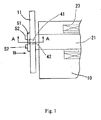
- the grinding wheel 11 is fixed, via a main spindle 21, to the wheel head 10 that moves to and from relative to a workpiece (not shown) on a bed (not shown) of a grinding machine (not shown).
- the main spindle 21 is rotatably supported by the wheel head 10 via a bearing (not shown) and rotated by a built-in motor 23.
- the grinding wheel 11 is fixed on a left end surface 21a of the main spindle 21 by a grinding wheel-fixing structure 30 as specifically shown in FIG. 2 (sectional view taken along the line A-A of FIG. 1 ).
- the grinding wheel 11 is sandwiched between a substantially discoid flange 51 and the end surface 21 a of the main spindle 21 and, as shown in FIG.
- bolts 52 equiangularly arranged ten bolts, for example.
- bolt insertion holes 53 and 55 that extend in the axial direction are passed through a core 32 of the grinding wheel 11, described later, and the flange 51, respectively, at the same angular positions.
- the tip screw portions of the bolts 52 which are hexagon socket head cap screws that are passed through the bolt insertion holes 53 and 55, are respectively screwed into screw holes 56, which are open at the end surface of the main spindle 21, whereby the grinding wheel 11 is fixed.
- the driving motor for the main spindle 21 is not limited to the built-in motor 23.
- a motor that is directly connected to the right end (not shown) of the main spindle 21, a motor that drives, via a belt-type driving mechanism (not shown), a pulley that is fixed to the same end portion, or the like can be employed as the driving motor.
- the grinding wheel 11 includes the discoid core 32 and a grindstone layer 35, which functions as the grindstone portion, in which a plurality of separate grindstone chips 33 are fixed, and which is formed on the outer circumferential surface of the core 32 with an adhesive layer 34 interposed between the core 32 and the grind stone layer 35.
- the grindstone chips 33 are obtained by bonding super abrasive grains, such as CBN grains or diamond, with a binder, such as a vitrified bond or a metal bond, in a matrix configuration.
- a side surface 33a of each of the grindstone chips 33 is slightly projected relative to the end surface 32a of the core 32 so that the end surface 32a of the core 32 and a workpiece do not interfere with each other when an end surface of the workpiece is ground.
- the core 32 of the grinding wheel 11 is formed of a steel, such as iron, for example.
- coating films 25 and 26 for preventing attachment of foreign matter are provided on the portions, with which the flying chippings and/or coolant can be brought into contact when grinding is performed using the grinding wheel 11.
- the coating films 25 and 26 are preferably such that the friction coefficient of the surface thereof is small, that is, the coating films 25 and 26 have low-friction properties and are therefore slippery, and are not adhesive.
- fluoroplastic that has these properties is applied as the coating films 25 and 26.
- the fluoroplastic herein is, for example, tetrafluoroethylene/perfiuoro(alkyl vinyl ether) copolymer (PFA), polytetrafluoroethylene (PTFE), tetrafluoroethylene/hexafluoropropylene copolymer (FEP), polyvinilydene fluoride (PVDF), polychlorotrifluoroethylene (PCTFE), ethylene-chlorotrifluoroethylene copolymer (ECTFE), or the like.
- PFA which is low in friction and excellent in non-adhesiveness and resistance to corrosion, is applied. Which of the fluoroplastics is applied is determined based on the material for the core 32 etc. to be coated and properties of these fluoroplastics.
- a surface-roughing treatment is performed to improve the adhesiveness to the fluoroplastic.
- the surface-roughing treatment is performed by performing a shot blasting process that roughs the surface of the core 32 etc., with the use of alumina powder or the like and application of the fluoroplastic (PFA) is then performed.
- PFA fluoroplastic
- surface roughening of the both end surfaces 32a of the core 32 may be performed by performing conversion treatment with the use of a chemical agent.
- the applied fluoroplastic is dried and thereafter, the fluoroplastic coating is finished after a firing step.
- the portions of the both end surfaces 32a of the core 32, with which the flange 51 and the end surface 21a of the main spindle 21 are brought into contact, are masked at the time of coating, so that these portions are not provided with the fluoroplastic coating.
- the flange 51 is provided with inner holes that have the same diameter as those of the inner holes 42 of the core 32 of the grinding wheel 11.
- the flange 51 is in close contact with the portion of the left end surface 32a of the core 32, which portion is not applied with the fluoroplastic coating film 25, and the bolts 52 are inserted into the bolt insertion holes 55 from the outer side for fixation.
- the flange 51 is made of steel and receives the pressing force applied by the heads of the bolts 52, so that the flange 51 has a function of distributing the stress due to fastening that concentrates at the portion around each of the bolt insertion holes 53 of the core 32.
- the diameter of the flange 51 is set significantly greater than that of the circle that the circumferences of the bolt insertion holes 53 provided in the core 32, through which the bolts 52 are passed, touch internally.
- the diameter of the flange 51 may be set equal to the diameter of the end surface of the main spindle 21 for symmetry.
- the flange 51 is provided with a coating film 27 that is a fluoroplastic coating similar to the coating film provided on the both end surfaces 32a of the core 32 for preventing attachment of foreign matter at the portion with which the coolant and/or chippings suspended in the air can be brought into contact when grinding is performed using the grinding wheel 11.
- coating films 25, 26, and 27, which are the fluoroplastic coatings provided on the both end surfaces 32a of the core 32 and the flange 51 instead of the coating films 25, 26, and 27, which are the fluoroplastic coatings provided on the both end surfaces 32a of the core 32 and the flange 51, coating films 47, 48, and 49, which are electroless nickel-fluoroplastic platings, may be formed on the flange 51 and the both end surfaces 32a of the core 32 by an electroless plating process by immersing the core 32 and the flange 51 in a plating solution that is obtained by mixing a predetermined amount of PTFE, which is a fluoroplastic, with a nickel plating solution (see FIG. 2 ).
- PTFE which is a fluoroplastic
- the friction coefficient of the surface of the electroless nicltel-fluoroplastic plating films 47, 48, and 49 is small, that is, the coating films 47, 48, and 49 are slippery, and are excellent in resistance to abrasion, so that it is possible to effectively prevent attachment of the chippings, suspended in the air, etc., to the core 32 for a long period of time.
- a configuration may be employed, in which phosphate coating films 57, 58, and 59 are provided on the both end surfaces 32a of the core 32 and the flange 51 by performing a parkerizing process, instead of the fluoroplastic coating films 25, 26, and 27 provided on the both end surfaces 32a of the core 32 and the flange 51 (see FIG 2 ).
- the parkerizing process is a conversion process that produces a coating film made of a phosphate of Mn, Fe, etc. on the surface of a steel material by immersing the steel material into a phosphate solution.
- the core 32 etc. that are base materials are washed. Then, the core 32 etc.
- a bathing process in a phosphate bath is performed. After the bathing process in the phosphate bath is performed, the workpiece is again washed with water and dried by heated air current, and the process is finished.
- a manganese phosphate coating film which is slippery, be formed and also in this way, the effects similar to those described above are achieved.
- the washed-away chippings and the sprayed coolant are scattered into the air and suspended therein and fall downward due to the gravity in a short time. Thereafter, the chippings and the coolant pass through the collecting passage (not shown) provided to collect the coolant and are colleted in the collecting tank (not shown).
- the rotation balance of the grinding wheel 11 is not lost and vibration is not caused, so that the chatter mark is not imprinted on the ground surface and a high quality is maintained.
- the portion of the core 32, at which the flange 51 and the left end surface 32a of the core 32 are brought into contact with each other, and the portion of the core 32, at which the right end surface 32a of the core 32 and the end surface 21a of the main spindle 21 are brought into contact with each other, which portions are located at center portions of the both end surfaces 32a of the core 32a and function as the installation portions for installation onto the grinding machine, are not provided with the fluoroplastic coating films 25 and 26.
- the core 32 is firmly fixed without any slip and stably rotated with the rotation of the main spindle 21 of the grinding machine.
- the grindstone layer 35 which functions as the grindstone portion, is formed on the outer circumferential surface of the core 32 of the grinding wheel 11.
- the second embodiment differs from the first embodiment in the shape of the core 32 and therefore, the difference will be described and the description of other operations, construction, etc. that are similar to those of the first embodiment will be omitted.
- the discoid core 36 includes: both end surfaces 36a at the center portions of the disc that have a circular profile and are parallel with each other; both curved surfaces 36b that are formed with a predetermined curvature R from the peripheral circular portions of the both end surfaces 36a toward the periphery of the disc of the core 36; and both end surfaces 36c that connect between the end portions of the both curved surfaces 36b and the peripheries of the core 36 and are parallel with each other.
- the outer diameter of the both end surfaces 36a of the core 36 is substantially equal to the outer diameter of the flange 51 that is interposed between the heads of the bolts 52 and the left end surface 36a of the core 36 when the grinding wheel 12 is fixed to the main spindle 21.
- the core 36 is formed so that the thickness between the both end surfaces 36a is thin.
- the both curved surfaces 36b are formed with the predetermined curvature R from the peripheral circular portions of the both end surfaces 36a toward the periphery of the discoid core 36.
- the portions of the both curved surfaces 36b and the both end surfaces 36c of the core 36 and the portion of the flange 51, with which portions the chippings and coolant suspended in the air can be brought into contact when grinding is performed by the grinding wheel 12, are applied with fluoroplastic (PFA) coating films 28, 29, and 31 for preventing attachment of foreign matter that each have a low friction coefficient and are therefore slippery.
- PFA fluoroplastic
- the chippings that try to attach to the both curved surfaces 36b of the core 36 are flown toward the periphery of the grinding wheel 12 on the both curved surfaces 36b by the centrifugal force generated by the rotation of the grinding wheel 12 and discharged outward (see the arrows) from circumferential portions 39 at which the both curved surfaces 36b and the both end surfaces 36c connect with each other.
- the chippings are not accumulated at corner portions 38 at which the both end surfaces 36c of the core 36 and the grindstone layer 37 that slightly protrudes outward relative to the end surfaces 36c of the core 36 meet each other.
- the chippings do not attach to the core 36, the rotation balance of the grinding wheel 12 is not lost, and vibration is not caused, so that the chatter mark is not imprinted on the ground surface and a high quality is maintained.
- the left end surface 36a of the core 36 which is a portion at which the flange 51 and the core 36 are in contact with each other, and the right end surface 36a that is brought into contact with the end surface 21a of the main spindle 21, are not provided with the fluoroplastic coating films 28 and 29.
- the both curved surfaces 36b of the core 36 are formed from the periphery of the both end surfaces 36a of the core 36.
- the curved surfaces 36b of the core 36 may start from the positions that are offset radially outward from the peripheries of the both end surfaces 36a by a predetermined amount.
- the portions of the both end surfaces of the grinding wheel 12, with which portions the main spindle 21 and the flange 51 are brought into contact are not provided with the fluoroplastic coating films 28 and 29 that are slippery.
- the grinding wheel 11 according to the invention includes one grinding wheel for grinding a cam on a camshaft
- the invention is not limited to this embodiment.
- the invention can be applied to a grinding machine, in which two grinding wheels are disposed for grinding cams on a camshaft, on which two cams for IN port or OUT port are arranged as in the case of the camshaft for a four-valve engine, for example.
- the two grinding wheels are disposed so as to match the arrangement of the cams, with the end surfaces of the two grinding wheels facing each other, and the rotation center portion of each of the two grinding wheels is fixed by one main spindle 21 so as to rotate together.
- the fluoroplastic coating film is provided on the portion of the core, with which foreign matter, such as chippings, can be brought into contact.
- the portion, at which the flange 51 and the core of the grinding wheel disposed on the outer side are brought into contact with each other, and the portion, at which the core of the grinding wheel disposed on the inner side and the end surface 21a of the main spindle 21 are brought into contact with each other, which portions function as the installation portions for installation onto the grinding machine, are not provided with the fluoroplastic coating films.
- the cores 32 and 36 that constitute the grinding wheels 11 and 12 are made of steel, such as iron
- the invention is not limited to these embodiments.
- the invention may be applied to a grinding machine in which the core is made of light metal, such as aluminum, or to a grinding machine in which the surface of the core is subjected to various rustproof treatments (black oxidation, various chromate treatments, etc.), and it is expected that similar effects be achieved.
- the grinding wheels 11 and 12 according to the invention are for grinding a cam on a camshaft.
- the invention is not limited to the embodiments.
- the invention can be applied to a cylindrical grinding machine, a surface grinding machine, and other grinding machines, and it is expected that the effects similar to those achieved by these embodiments be achieved.
- a grinding wheel (11) having a grindstone portion (35) formed on a core (32) includes slippery fluoroplastic coating films (25, 26, 27) that prevent attachment of foreign matter, the coating films being provided on the portions of the core (32), with which portions the foreign matter can be brought into contact.
Landscapes
- Engineering & Computer Science (AREA)
- Mechanical Engineering (AREA)
- Polishing Bodies And Polishing Tools (AREA)
Abstract
Description
- The invention relates to a grinding wheel that is used in a state where the grinding wheel is installed on a wheel spindle of a grinding machine.
- As a grinding wheel for a common grinding machine, a grinding wheel is available, in which a grindstone layer containing CBN or diamond is formed on an outer circumferential surface of a discoid grindstone core made of steel, in which an installation hole for use in installing the grinding wheel on a wheel spindle is formed in the center portion, and in which fixation hole portions for use in fixing the grinding wheel to the wheel spindle or the like are formed around the installation hole. As a grinding wheel for a grinding machine that rotates at a high speed, one that is described in Japanese Patent Application Publication No.
2002-200565 JP-A-2002-200565 grindstone layer 35 is formed on the outer circumferential surface of a discoidaluminum alloy core 32 with anadhesive layer 34 interposed therebetween, an installation hole 45 for use in installing thecore 32 to a wheelmain spindle 21 is formed at a center portion of thecore 32, and a plurality offixation holes grinding wheel 31 to the wheelmain spindle 21. Thegrinding wheel 31 is installed on a flange portion of the grindingmain spindle 21 via aflange 51 etc. with the use of a plurality ofinstallation bolts 52 through thefixation holes core 32, which portions can be splashed with coolant during grinding. - However, regarding the above-described related art, a situation sometimes occurs where, as machining of workpieces with the use of the grinding wheel is continued, the rotation balance of the grinding wheel is gradually lost, vibration occurs in the grinding wheel, and the chatter mark is imprinted on the ground surface of the workpiece, which results in the degradation of the plane accuracy. Conventionally, in order to ensure high plane accuracy of the machined surface, a measure has to be taken,
in which the grinding machine is stopped during manufacturing and balancing of the grindstone is redone, or in which an expensive automatic balancer is introduced into the facility to correct the lost rotation balance. - After a diligent study of such a problem, the inventor has found that chippings, coolant mist, etc. suspended in the air attach to the grindstone core during grinding and the attached chippings are accumulated on the both end surfaces of the core, which can result in losing the rotation balance of the grinding wheel.
- In light of the new problem of losing the rotation balance of a grinding wheel due to attachment of chippings, an object of the invention is to prevent losing the rotation balance and occurrence of the chatter of the grinding wheel that rotates, without stopping manufacturing and without introducing an expensive automatic balancer.
- In order to solve the above problem, the invention is characterized in that a grinding wheel having a grindstone portion formed on a core includes a slippery coating film that prevents attachment of foreign matter, the coating film being provided on a portion of the core, with which portion the foreign matter can be brought into contact.
- According to the grinding wheel configured as described above, attachment of foreign matter to the core is prevented by the coaling films provided on the portion of the core, with which portion the foreign matter can be brought into contact. Thus, the situation is avoided where the grinding wheel that is rotated is unbalanced due to attachment of foreign matter, such as chippings, vibration in the rotation occurs, and the quality of the ground surface of the workpiece is degraded.
- A feature of the invention is that the coating film is a fluoroplastic coating.
- According to the grinding wheel configured as described above, the coating film applied on the portion of the core, with which portion foreign matter can be brought into contact, is the fluoroplastic coating. The surface of the fluoroplastic is low in friction, that is, slippery, and is excellent in non-adhesiveness. Thus, attachment of the chippings and coolant, suspended in the air, to the core is effectively prevented.
- A feature of the invention is that the coating film is a plating film that contains fluoroplastic.
- According to the grinding wheel configured as described above, the coating film applied on the portion of the core, with which portion foreign matter can be brought into contact, is the plating containing fluoroplastic. The surface of the plating is low in faction, that is, slippery, and is excellent in resistance to abrasion. Thus, attachment of the chippings and coolant, suspended in the air, to the core is effectively prevented for a long period of time.
- A feature of the invention is that the coating film is a phosphate conversion layer formed by a parkerizing process.
- According to the grinding wheel configured as described above, the coating film applied on the portion of the core, with which portion foreign matter can be brought into contact, is formed by a parkerizing process. The surface of the phosphate conversion coating film formed by the parkerizing process is low in friction, that is, slippery. Thus, attachment of the chippings and coolant, suspended in the air, to the core is prevented.
- A feature of the invention is that the core is discoid and the grindstone portion is formed on the outer circumferential surface of the core.
- According to the grinding wheel configured as described above, the core is discoid and the grindstone portion is formed on the outer circumferential surface of the core. Thus, it is possible to effectively prevent the rotated grinding wheel from being unbalanced by forming the coating film on the both end surfaces of the core, on which surfaces the coating films can be easily formed, without providing the grindstone portion with the coating film for preventing attachment of foreign matter.
- A feature of the invention is that the coating film is not provided on a portion for installation onto a grinding machine, which portion is provided at a center portion of each of both end surfaces of the discoid core.
- According to the grinding wheel configured as described above, the coating film for preventing attachment of foreign matter is not provided on the portion for installation onto the grinding machine, which portion is provided at a center portion of each of the both end surfaces of the discoid core. Thus, when the discoid core is installed on the grinding machine, the discoid core is firmly fixed without any slip and stably rotated with the rotation of the installation spindle of the grinding machine.
- A feature of the invention is that each of the both end surfaces of the discoid core is formed to have a curved surface so that the thickness of the core between the both end surfaces is thin in a center portion of the discoid core and the thickness of the core between the both end surfaces increases toward the periphery of the discoid core.
- According to the grinding wheel configured as described above, a curved surface is formed on each of the both end surfaces of the discoid core, the thickness of the core between the both end surfaces is thin in the center portion of the discoid core and, the thickness thereof increases toward the periphery of the discoid core according to a predetermined curvature. Thus, the chippings and the coolant mist attached to the curved surface portions of the both end surfaces are flown toward the periphery of the grinding wheel on the curved surface portions by the centrifugal force generated by the rotation of the grinding wheel and discharged from circumferential portions at which the both curved surfaces and the both end surfaces connect with each other. Thus, the chippings etc. are flown on the both end surfaces of the core toward the periphery by the centrifugal force, so that the situation is effectively avoided where the chippings etc. are accumulated at corner portions at which the both end surfaces of the core and the grindstone portion that slightly protrudes outward relative to the end surfaces of the core meet each other.
- The foregoing and further objects, features and advantages of the invention will become apparent from the following description of example embodiments with reference to the accompanying drawings, wherein like numerals are used to represent like elements and wherein:
-
FIG. 1 is a partial side view that shows a state where a grinding wheel of a first embodiment according to the invention is fixed to a wheel head of a grinding machine; -
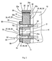
FIG. 2 is a sectional view taken along the line A-A ofFIG. 1 ; -
FIG. 3 is a partial front view of the grinding wheel on the arrow B inFIG. 1 ; and -
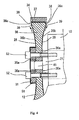
FIG. 4 is a sectional view of a grinding wheel of a second embodiment according to the invention. - A first embodiment of a grinding wheel 1 according to the invention will be described below with reference to
FIGS. 1 to 3 . As shown inFIG 1 that shows part of the side view of awheel head 10, thegrinding wheel 11 is fixed, via amain spindle 21, to thewheel head 10 that moves to and from relative to a workpiece (not shown) on a bed (not shown) of a grinding machine (not shown). Themain spindle 21 is rotatably supported by thewheel head 10 via a bearing (not shown) and rotated by a built-inmotor 23. Acylindrical boss 41 that is inserted into aninner hole 42 of thegrinding wheel 11 when thegrinding wheel 11 is fixed to themain spindle 21, is provided on themain spindle 21 so as to protrude from one end of themain spindle 21 coaxially with themain spindle 21. Thegrinding wheel 11 is fixed on aleft end surface 21a of themain spindle 21 by a grinding wheel-fixing structure 30 as specifically shown inFIG. 2 (sectional view taken along the line A-A ofFIG. 1 ). The grindingwheel 11 is sandwiched between a substantiallydiscoid flange 51 and theend surface 21 a of themain spindle 21 and, as shown inFIG. 3 , removably fixed on theleft end surface 21a of themain spindle 21 with a plurality of bolts 52 (equiangularly arranged ten bolts, for example). Thus,bolt insertion holes core 32 of thegrinding wheel 11, described later, and theflange 51, respectively, at the same angular positions. The tip screw portions of thebolts 52, which are hexagon socket head cap screws that are passed through thebolt insertion holes screw holes 56, which are open at the end surface of themain spindle 21, whereby thegrinding wheel 11 is fixed. Thus, two members, thegrinding wheel 11 and theflange 51, are fixed to theend surface 21a of themain spindle 21 as a unit by screwing thebolts 52 with the use of a well-known hexagon wrench (not shown). Various roller bearings, slide bearings, fluid dynamic bearings, etc. can be used as the bearing. The driving motor for themain spindle 21 is not limited to the built-inmotor 23. A motor that is directly connected to the right end (not shown) of themain spindle 21, a motor that drives, via a belt-type driving mechanism (not shown), a pulley that is fixed to the same end portion, or the like can be employed as the driving motor. - As shown in
FIG 2 , thegrinding wheel 11 includes thediscoid core 32 and agrindstone layer 35, which functions as the grindstone portion, in which a plurality ofseparate grindstone chips 33 are fixed, and which is formed on the outer circumferential surface of thecore 32 with anadhesive layer 34 interposed between thecore 32 and thegrind stone layer 35. Thegrindstone chips 33 are obtained by bonding super abrasive grains, such as CBN grains or diamond, with a binder, such as a vitrified bond or a metal bond, in a matrix configuration. Aside surface 33a of each of thegrindstone chips 33 is slightly projected relative to theend surface 32a of thecore 32 so that theend surface 32a of thecore 32 and a workpiece do not interfere with each other when an end surface of the workpiece is ground. - The
core 32 of thegrinding wheel 11 is formed of a steel, such as iron, for example. On bothend surfaces 32a of thecore 32, coating films 25 and 26 for preventing attachment of foreign matter are provided on the portions, with which the flying chippings and/or coolant can be brought into contact when grinding is performed using thegrinding wheel 11. The coating films 25 and 26 are preferably such that the friction coefficient of the surface thereof is small, that is, the coating films 25 and 26 have low-friction properties and are therefore slippery, and are not adhesive. Thus, fluoroplastic that has these properties is applied as the coating films 25 and 26. The fluoroplastic herein is, for example, tetrafluoroethylene/perfiuoro(alkyl vinyl ether) copolymer (PFA), polytetrafluoroethylene (PTFE), tetrafluoroethylene/hexafluoropropylene copolymer (FEP), polyvinilydene fluoride (PVDF), polychlorotrifluoroethylene (PCTFE), ethylene-chlorotrifluoroethylene copolymer (ECTFE), or the like. In this embodiment, PFA, which is low in friction and excellent in non-adhesiveness and resistance to corrosion, is applied. Which of the fluoroplastics is applied is determined based on the material for the core 32 etc. to be coated and properties of these fluoroplastics. - In the process of coating with fluoroplastic, first, removal of grease from the core 32 etc. that are base materials is performed. Next, a surface-roughing treatment is performed to improve the adhesiveness to the fluoroplastic. The surface-roughing treatment is performed by performing a shot blasting process that roughs the surface of the core 32 etc., with the use of alumina powder or the like and application of the fluoroplastic (PFA) is then performed. When this is performed, surface roughening of the both
end surfaces 32a of the core 32 may be performed by performing conversion treatment with the use of a chemical agent. Then, the applied fluoroplastic is dried and thereafter, the fluoroplastic coating is finished after a firing step. In order to achieve firm fixation so that a displacement between thegrinding wheel 11 and themain spindle 21 does not occur even when the grindingwheel 11 rotates, the portions of the bothend surfaces 32a of the core 32, with which theflange 51 and theend surface 21a of themain spindle 21 are brought into contact, are masked at the time of coating, so that these portions are not provided with the fluoroplastic coating. - The
flange 51 is provided with inner holes that have the same diameter as those of theinner holes 42 of thecore 32 of thegrinding wheel 11. Theflange 51 is in close contact with the portion of theleft end surface 32a of the core 32, which portion is not applied with the fluoroplastic coating film 25, and thebolts 52 are inserted into the bolt insertion holes 55 from the outer side for fixation. Theflange 51 is made of steel and receives the pressing force applied by the heads of thebolts 52, so that theflange 51 has a function of distributing the stress due to fastening that concentrates at the portion around each of the bolt insertion holes 53 of thecore 32. The diameter of theflange 51 is set significantly greater than that of the circle that the circumferences of the bolt insertion holes 53 provided in thecore 32, through which thebolts 52 are passed, touch internally. The diameter of theflange 51 may be set equal to the diameter of the end surface of themain spindle 21 for symmetry. Theflange 51 is provided with a coating film 27 that is a fluoroplastic coating similar to the coating film provided on the bothend surfaces 32a of thecore 32 for preventing attachment of foreign matter at the portion with which the coolant and/or chippings suspended in the air can be brought into contact when grinding is performed using thegrinding wheel 11. - In the above described embodiment, instead of the coating films 25, 26, and 27, which are the fluoroplastic coatings provided on the both
end surfaces 32a of thecore 32 and theflange 51, coating films 47, 48, and 49, which are electroless nickel-fluoroplastic platings, may be formed on theflange 51 and the bothend surfaces 32a of the core 32 by an electroless plating process by immersing thecore 32 and theflange 51 in a plating solution that is obtained by mixing a predetermined amount of PTFE, which is a fluoroplastic, with a nickel plating solution (seeFIG. 2 ). Also in this way, as in the case of the fluoroplastic coating films 25, 26, and 27, the friction coefficient of the surface of the electroless nicltel-fluoroplastic plating films 47, 48, and 49 is small, that is, the coating films 47, 48, and 49 are slippery, and are excellent in resistance to abrasion, so that it is possible to effectively prevent attachment of the chippings, suspended in the air, etc., to thecore 32 for a long period of time. - Further, a configuration may be employed, in which phosphate coating films 57, 58, and 59 are provided on the both
end surfaces 32a of thecore 32 and theflange 51 by performing a parkerizing process, instead of the fluoroplastic coating films 25, 26, and 27 provided on the bothend surfaces 32a of thecore 32 and the flange 51 (seeFIG 2 ). The parkerizing process is a conversion process that produces a coating film made of a phosphate of Mn, Fe, etc. on the surface of a steel material by immersing the steel material into a phosphate solution. As a first step of the process, the core 32 etc. that are base materials, are washed. Then, the core 32 etc. are washed with water and then, a bathing process in a phosphate bath is performed. After the bathing process in the phosphate bath is performed, the workpiece is again washed with water and dried by heated air current, and the process is finished. In the invention, it is preferable that a manganese phosphate coating film, which is slippery, be formed and also in this way, the effects similar to those described above are achieved. - Next, operations will be described. A case will be described where grinding of cams of an automobile camshaft, for example, is performed by the grinding
wheel 11 configured as described above. In general, when the cams of an automobile camshaft are ground, in order to ensure a high plane accuracy after grinding, the grindingwheel 11 is rotated at a high speed and the cam surfaces are ground by thegrindstone layer 35, which functions as the grindstone portion formed on the outer circumferential surface of thegrinding wheel 11. During this process, in order to remove the heat generated due to grinding and to wash away and remove the chippings produced by the grinding, a coolant is sprayed to the vicinity of the point of contact between the cam and thegrindstone layer 35 of thegrinding wheel 11. The washed-away chippings and the sprayed coolant are scattered into the air and suspended therein and fall downward due to the gravity in a short time. Thereafter, the chippings and the coolant pass through the collecting passage (not shown) provided to collect the coolant and are colleted in the collecting tank (not shown). - However, part of the chippings and coolant that are scattered into the air and suspended therein hit and try to attach to the portions of the both
end surfaces 32a of thecore 32 and theflange 51 of thegrinding wheel 11 rotated at a high speed, with which portions the chippings and the coolant can be brought into contact. However, the predetermined portions of the bothend surfaces 32a of thecore 32 and theflange 51 are applied with the fluoroplastic (PFA) coating films 25, 26, and 27 that each have a low friction coefficient and are therefore slippery, so that the chippings and the coolant are scattered due to rotation of thegrinding wheel 11 and cannot attach to thegrinding wheel 11. Thus, the rotation balance of thegrinding wheel 11 is not lost and vibration is not caused, so that the chatter mark is not imprinted on the ground surface and a high quality is maintained. In addition, the portion of the core 32, at which theflange 51 and theleft end surface 32a of the core 32 are brought into contact with each other, and the portion of the core 32, at which theright end surface 32a of thecore 32 and theend surface 21a of themain spindle 21 are brought into contact with each other, which portions are located at center portions of the bothend surfaces 32a of thecore 32a and function as the installation portions for installation onto the grinding machine, are not provided with the fluoroplastic coating films 25 and 26. Thus, thecore 32 is firmly fixed without any slip and stably rotated with the rotation of themain spindle 21 of the grinding machine. - In addition, the
grindstone layer 35, which functions as the grindstone portion, is formed on the outer circumferential surface of thecore 32 of thegrinding wheel 11. Thus, it is possible to effectively prevent the occurrence of unbalance of thegrinding wheel 11 that is rotated at a high speed, by forming the coating films on the bothend surfaces 32a of the core 32, on which the coating films can be easily formed, without providing thegrindstone layer 35 with the coating film for preventing attachment of foreign matter. - Next, a second embodiment according to the invention will be described with reference to
FIG. 4 . The second embodiment differs from the first embodiment in the shape of thecore 32 and therefore, the difference will be described and the description of other operations, construction, etc. that are similar to those of the first embodiment will be omitted. In the second embodiment, as shown inFIG 4 , thediscoid core 36 includes: bothend surfaces 36a at the center portions of the disc that have a circular profile and are parallel with each other; bothcurved surfaces 36b that are formed with a predetermined curvature R from the peripheral circular portions of the bothend surfaces 36a toward the periphery of the disc of the core 36; and both end surfaces 36c that connect between the end portions of the bothcurved surfaces 36b and the peripheries of thecore 36 and are parallel with each other. - The outer diameter of the both
end surfaces 36a of thecore 36 is substantially equal to the outer diameter of theflange 51 that is interposed between the heads of thebolts 52 and theleft end surface 36a of the core 36 when the grindingwheel 12 is fixed to themain spindle 21. Thecore 36 is formed so that the thickness between the bothend surfaces 36a is thin. In addition, the bothcurved surfaces 36b are formed with the predetermined curvature R from the peripheral circular portions of the bothend surfaces 36a toward the periphery of thediscoid core 36. The portions of the bothcurved surfaces 36b and the both end surfaces 36c of thecore 36 and the portion of theflange 51, with which portions the chippings and coolant suspended in the air can be brought into contact when grinding is performed by the grindingwheel 12, are applied with fluoroplastic (PFA) coatingfilms flange 51 and the bothcurved surfaces 36b and the both end surfaces 36c of the core 36, the chippings etc. are scattered due to rotation of thegrinding wheel 12 and do not attach to thegrinding wheel 12. In particular, the chippings that try to attach to the bothcurved surfaces 36b of the core 36 are flown toward the periphery of thegrinding wheel 12 on the bothcurved surfaces 36b by the centrifugal force generated by the rotation of thegrinding wheel 12 and discharged outward (see the arrows) fromcircumferential portions 39 at which the bothcurved surfaces 36b and the both end surfaces 36c connect with each other. Thus, the chippings are not accumulated atcorner portions 38 at which the both end surfaces 36c of thecore 36 and thegrindstone layer 37 that slightly protrudes outward relative to the end surfaces 36c of the core 36 meet each other. Thus, the chippings do not attach to thecore 36, the rotation balance of thegrinding wheel 12 is not lost, and vibration is not caused, so that the chatter mark is not imprinted on the ground surface and a high quality is maintained. In addition, theleft end surface 36a of the core 36, which is a portion at which theflange 51 and the core 36 are in contact with each other, and theright end surface 36a that is brought into contact with theend surface 21a of themain spindle 21, are not provided with thefluoroplastic coating films core 32 is installed on the grinding machine, thecore 32 is firmly fixed without any slip and stably rotated with the rotation of themain spindle 21 of the grinding machine. - In the second embodiment, the both
curved surfaces 36b of the core 36 are formed from the periphery of the bothend surfaces 36a of thecore 36. However, considering the ease of manufacturing, it is unnecessary that the position, from which the bothcurved surfaces 36b start, coincide with the periphery of the bothend surfaces 36a. Thecurved surfaces 36b of the core 36 may start from the positions that are offset radially outward from the peripheries of the bothend surfaces 36a by a predetermined amount. However, also in this case, the portions of the both end surfaces of thegrinding wheel 12, with which portions themain spindle 21 and theflange 51 are brought into contact, are not provided with thefluoroplastic coating films - In addition, although the
grinding wheel 11 according to the invention includes one grinding wheel for grinding a cam on a camshaft, the invention is not limited to this embodiment. For example, the invention can be applied to a grinding machine, in which two grinding wheels are disposed for grinding cams on a camshaft, on which two cams for IN port or OUT port are arranged as in the case of the camshaft for a four-valve engine, for example. In this case, the two grinding wheels are disposed so as to match the arrangement of the cams, with the end surfaces of the two grinding wheels facing each other, and the rotation center portion of each of the two grinding wheels is fixed by onemain spindle 21 so as to rotate together. Also in this case, as in the case of the above embodiment, the fluoroplastic coating film is provided on the portion of the core, with which foreign matter, such as chippings, can be brought into contact. The portion, at which theflange 51 and the core of the grinding wheel disposed on the outer side are brought into contact with each other, and the portion, at which the core of the grinding wheel disposed on the inner side and theend surface 21a of themain spindle 21 are brought into contact with each other, which portions function as the installation portions for installation onto the grinding machine, are not provided with the fluoroplastic coating films. With this configuration, the situation is avoided where two grinding wheels that are rotated at a high speed is unbalanced due to attachment of foreign matter and vibration in the rotation is caused, resulting in degradation of the quality of the ground surface of the workpiece. In addition, when the two, discoid cores are installed on the grinding machine, the cores are firmly fixed without any slip and are stably rotated with the rotation of themain spindle 21 of the grinding machine. - Although in the Burst and second embodiments, the
cores wheels
in which the core is made of light metal, such as aluminum, or to a grinding machine in which the surface of the core is subjected to various rustproof treatments (black oxidation, various chromate treatments, etc.), and it is expected that similar effects be achieved. - In the description of the first and second embodiments, the grinding
wheels
A grinding wheel (11) having a grindstone portion (35) formed on a core (32) includes slippery fluoroplastic coating films (25, 26, 27) that prevent attachment of foreign matter, the coating films being provided on the portions of the core (32), with which portions the foreign matter can be brought into contact.
Claims (7)
- A grinding wheel having a grindstone portion formed on a core, the grinding wheel comprising a slippery coating film that prevents attachment of foreign matter, the coating film being provided on a portion of the core, with which portion the foreign matter can be brought into contact.
- The grinding wheel according to claim 1, wherein the coating film is a fluoroplastic coating.
- The grinding wheel according to claim 1, wherein the coating film is a plating film that contains fluoroplastic.
- The grinding wheel according to claim 1, wherein the coating film is a phosphate conversion layer formed by a parkerizing process.
- The grinding wheel according to any one of claims 1 to 4, wherein the core is discoid and the grindstone portion is formed on an outer circumferential surface of the core.
- The grinding wheel according to claim 5, wherein the coating film is not provided on a portion for installation onto a grinding machine, which portion is provided at a center portion of each of both end surfaces of the discoid core.
- The grinding wheel according to claim 6, wherein each of the both end surfaces of the discoid core is formed to have a curved surface so that a thickness of the core between the both end surfaces is thin in a center portion of the discoid core and the thickness of the core between the both end surfaces increases toward a periphery of the discoid core.
Applications Claiming Priority (1)
| Application Number | Priority Date | Filing Date | Title |
|---|---|---|---|
| JP2008330750A JP5332597B2 (en) | 2008-12-25 | 2008-12-25 | Grinding wheel |
Publications (3)
| Publication Number | Publication Date |
|---|---|
| EP2202032A2 true EP2202032A2 (en) | 2010-06-30 |
| EP2202032A3 EP2202032A3 (en) | 2011-03-23 |
| EP2202032B1 EP2202032B1 (en) | 2012-05-16 |
Family
ID=41800534
Family Applications (1)
| Application Number | Title | Priority Date | Filing Date |
|---|---|---|---|
| EP09177709A Not-in-force EP2202032B1 (en) | 2008-12-25 | 2009-12-02 | Grinding wheel with non-stick coating |
Country Status (3)
| Country | Link |
|---|---|
| US (1) | US8348728B2 (en) |
| EP (1) | EP2202032B1 (en) |
| JP (1) | JP5332597B2 (en) |
Cited By (1)
| Publication number | Priority date | Publication date | Assignee | Title |
|---|---|---|---|---|
| CN104114446A (en) * | 2012-02-15 | 2014-10-22 | 三菱重工业株式会社 | Rudder device for marine vessel, and marine vessel provided with same |
Families Citing this family (7)
| Publication number | Priority date | Publication date | Assignee | Title |
|---|---|---|---|---|
| CN102413983A (en) * | 2009-04-29 | 2012-04-11 | 贝卡尔特公司 | Cutting wire with abrasive particles partially embedded in a metal wire and partially retained by an organic binder |
| US8567385B2 (en) * | 2011-09-22 | 2013-10-29 | Chung-Shan Institute of Science and Technology, Armaments, Bureau, Ministry of National Defense | Fret saw including a cutting wire provided with fixed abrasive grains each including a core coated with a hard film |
| JP2014151419A (en) * | 2013-02-13 | 2014-08-25 | Disco Abrasive Syst Ltd | Grinding wheel |
| CN107155318B (en) * | 2015-04-07 | 2020-03-31 | 惠普发展公司有限责任合伙企业 | Polishing method |
| CN106695579B (en) * | 2016-12-21 | 2018-02-09 | 江苏索力德机电科技股份有限公司 | A kind of super hard abrasive emery wheel |
| WO2019003640A1 (en) * | 2017-06-30 | 2019-01-03 | 兼房株式会社 | Cutlery |
| CN112757177B (en) * | 2021-01-11 | 2022-06-28 | 中铁隆昌铁路器材有限公司 | Steel rail milling and grinding vehicle grinding wheel unbalance amount adjusting hole filling glue and using method thereof |
Citations (1)
| Publication number | Priority date | Publication date | Assignee | Title |
|---|---|---|---|---|
| JP2002200565A (en) | 2000-12-28 | 2002-07-16 | Toyoda Mach Works Ltd | Grinding wheel for high speed rotation and manufacturing method therefor |
Family Cites Families (11)
| Publication number | Priority date | Publication date | Assignee | Title |
|---|---|---|---|---|
| US1908218A (en) * | 1931-11-11 | 1933-05-09 | Micromatic Hone Corp | Abrasive stone holder |
| JPS4731739Y1 (en) * | 1968-08-27 | 1972-09-25 | ||
| JPS4823595B1 (en) * | 1969-06-17 | 1973-07-14 | ||
| US3636665A (en) * | 1970-04-15 | 1972-01-25 | Grinding Wheel Inst Inc | Segmented grinding wheel |
| JPS5917572Y2 (en) * | 1980-06-13 | 1984-05-22 | 豊田工機株式会社 | Grinding wheel |
| JPH0171062U (en) * | 1987-10-29 | 1989-05-11 | ||
| JPH07205033A (en) * | 1994-01-19 | 1995-08-08 | Hitachi Maxell Ltd | Abrasive whetstone for polishing finish of magnetic tape |
| JP2000094337A (en) * | 1998-09-18 | 2000-04-04 | Hitachi Metals Ltd | Super abrasive grain grinding wheel blade for cutting rare earth magnet and manufacture of it |
| US6517424B2 (en) * | 2000-03-10 | 2003-02-11 | Abrasive Technology, Inc. | Protective coatings for CMP conditioning disk |
| US6808802B2 (en) * | 2002-02-13 | 2004-10-26 | NxEdge, Inc. | Equipment coating |
| JP2004322230A (en) * | 2003-04-22 | 2004-11-18 | Read Co Ltd | Grinding wheel |
-
2008
- 2008-12-25 JP JP2008330750A patent/JP5332597B2/en not_active Expired - Fee Related
-
2009
- 2009-12-02 EP EP09177709A patent/EP2202032B1/en not_active Not-in-force
- 2009-12-16 US US12/639,608 patent/US8348728B2/en not_active Expired - Fee Related
Patent Citations (1)
| Publication number | Priority date | Publication date | Assignee | Title |
|---|---|---|---|---|
| JP2002200565A (en) | 2000-12-28 | 2002-07-16 | Toyoda Mach Works Ltd | Grinding wheel for high speed rotation and manufacturing method therefor |
Cited By (2)
| Publication number | Priority date | Publication date | Assignee | Title |
|---|---|---|---|---|
| CN104114446A (en) * | 2012-02-15 | 2014-10-22 | 三菱重工业株式会社 | Rudder device for marine vessel, and marine vessel provided with same |
| CN104114446B (en) * | 2012-02-15 | 2016-10-12 | 三菱重工业株式会社 | The rudder for ship device of boats and ships and possess the boats and ships of this rudder for ship device |
Also Published As
| Publication number | Publication date |
|---|---|
| JP5332597B2 (en) | 2013-11-06 |
| US20100167634A1 (en) | 2010-07-01 |
| EP2202032B1 (en) | 2012-05-16 |
| JP2010149240A (en) | 2010-07-08 |
| US8348728B2 (en) | 2013-01-08 |
| EP2202032A3 (en) | 2011-03-23 |
Similar Documents
| Publication | Publication Date | Title |
|---|---|---|
| EP2202032B1 (en) | Grinding wheel with non-stick coating | |
| US6457566B1 (en) | Disk brake rotor with visual wear indicator | |
| RU2678539C2 (en) | Method for producing brake disc and brake disc | |
| US5430926A (en) | Method of producing a rotatable brake component and bearing assembly | |
| EP2554969B1 (en) | Road surface member for tire testing machine and manufacturing method of the same | |
| US20140143992A1 (en) | Methods for treating a cast iron workpiece | |
| WO2014062208A1 (en) | Reduction of turbocharger core unbalance with balance washer | |
| US20020066185A1 (en) | Method of machining a hub bearing unit for a wheel of a motor vehicle | |
| US7927189B2 (en) | Superabrasive tool | |
| WO2014176202A1 (en) | Grinding and polishing tool | |
| GB2574492A (en) | Abrasive machining | |
| WO2004067296A1 (en) | Wheel bearing unit and method of manufacturing the bearing unit | |
| KR102308992B1 (en) | Wheel hub bearing unit for vehicles and associated method | |
| US6257963B1 (en) | Grinding worm for the continuous generating grinding of gear wheels | |
| US20100257737A1 (en) | Wheel assembly and method for making same | |
| CN202485863U (en) | Clamp system for balance detection of hydraulic torque converter assembly | |
| CN206455536U (en) | Inner arc grinding abrasive disk mechanism and brake block production equipment | |
| CN106103899B (en) | Rotor components with surfaces for checking concentricity | |
| US20050231025A1 (en) | Wheel support rolling bearing unit and manufacturing method therefor | |
| EP3900875B1 (en) | Bearing ring member production method, roller bearing production method, hub unit bearing production method, and vehicle production method | |
| RU2761847C1 (en) | Apparatus for straightening circular tools | |
| US11231079B2 (en) | Ferrous workpiece and method of manufacture | |
| JP2002200565A (en) | Grinding wheel for high speed rotation and manufacturing method therefor | |
| US20030096142A1 (en) | Dual coated cubic boron nitride cutting tool and method of employing same | |
| JP2004205009A (en) | Manufacturing method for pulley |
Legal Events
| Date | Code | Title | Description |
|---|---|---|---|
| PUAI | Public reference made under article 153(3) epc to a published international application that has entered the european phase |
Free format text: ORIGINAL CODE: 0009012 |
|
| AK | Designated contracting states |
Kind code of ref document: A2 Designated state(s): AT BE BG CH CY CZ DE DK EE ES FI FR GB GR HR HU IE IS IT LI LT LU LV MC MK MT NL NO PL PT RO SE SI SK SM TR |
|
| AX | Request for extension of the european patent |
Extension state: AL BA RS |
|
| PUAL | Search report despatched |
Free format text: ORIGINAL CODE: 0009013 |
|
| AK | Designated contracting states |
Kind code of ref document: A3 Designated state(s): AT BE BG CH CY CZ DE DK EE ES FI FR GB GR HR HU IE IS IT LI LT LU LV MC MK MT NL NO PL PT RO SE SI SK SM TR |
|
| AX | Request for extension of the european patent |
Extension state: AL BA RS |
|
| RIC1 | Information provided on ipc code assigned before grant |
Ipc: B24D 5/16 20060101ALI20110215BHEP Ipc: B24D 5/00 20060101ALI20110215BHEP Ipc: B24B 55/00 20060101AFI20100316BHEP |
|
| 17P | Request for examination filed |
Effective date: 20110923 |
|
| GRAP | Despatch of communication of intention to grant a patent |
Free format text: ORIGINAL CODE: EPIDOSNIGR1 |
|
| GRAS | Grant fee paid |
Free format text: ORIGINAL CODE: EPIDOSNIGR3 |
|
| GRAA | (expected) grant |
Free format text: ORIGINAL CODE: 0009210 |
|
| AK | Designated contracting states |
Kind code of ref document: B1 Designated state(s): AT BE BG CH CY CZ DE DK EE ES FI FR GB GR HR HU IE IS IT LI LT LU LV MC MK MT NL NO PL PT RO SE SI SK SM TR |
|
| REG | Reference to a national code |
Ref country code: GB Ref legal event code: FG4D |
|
| REG | Reference to a national code |
Ref country code: CH Ref legal event code: EP |
|
| REG | Reference to a national code |
Ref country code: AT Ref legal event code: REF Ref document number: 557823 Country of ref document: AT Kind code of ref document: T Effective date: 20120615 |
|
| REG | Reference to a national code |
Ref country code: IE Ref legal event code: FG4D |
|
| REG | Reference to a national code |
Ref country code: DE Ref legal event code: R096 Ref document number: 602009006996 Country of ref document: DE Effective date: 20120719 |
|
| REG | Reference to a national code |
Ref country code: NL Ref legal event code: VDEP Effective date: 20120516 |
|
| REG | Reference to a national code |
Ref country code: LT Ref legal event code: MG4D Effective date: 20120516 |
|
| PG25 | Lapsed in a contracting state [announced via postgrant information from national office to epo] |
Ref country code: LT Free format text: LAPSE BECAUSE OF FAILURE TO SUBMIT A TRANSLATION OF THE DESCRIPTION OR TO PAY THE FEE WITHIN THE PRESCRIBED TIME-LIMIT Effective date: 20120516 Ref country code: IS Free format text: LAPSE BECAUSE OF FAILURE TO SUBMIT A TRANSLATION OF THE DESCRIPTION OR TO PAY THE FEE WITHIN THE PRESCRIBED TIME-LIMIT Effective date: 20120916 Ref country code: FI Free format text: LAPSE BECAUSE OF FAILURE TO SUBMIT A TRANSLATION OF THE DESCRIPTION OR TO PAY THE FEE WITHIN THE PRESCRIBED TIME-LIMIT Effective date: 20120516 Ref country code: SE Free format text: LAPSE BECAUSE OF FAILURE TO SUBMIT A TRANSLATION OF THE DESCRIPTION OR TO PAY THE FEE WITHIN THE PRESCRIBED TIME-LIMIT Effective date: 20120516 Ref country code: NO Free format text: LAPSE BECAUSE OF FAILURE TO SUBMIT A TRANSLATION OF THE DESCRIPTION OR TO PAY THE FEE WITHIN THE PRESCRIBED TIME-LIMIT Effective date: 20120816 Ref country code: PL Free format text: LAPSE BECAUSE OF FAILURE TO SUBMIT A TRANSLATION OF THE DESCRIPTION OR TO PAY THE FEE WITHIN THE PRESCRIBED TIME-LIMIT Effective date: 20120516 Ref country code: CY Free format text: LAPSE BECAUSE OF FAILURE TO SUBMIT A TRANSLATION OF THE DESCRIPTION OR TO PAY THE FEE WITHIN THE PRESCRIBED TIME-LIMIT Effective date: 20120516 |
|
| REG | Reference to a national code |
Ref country code: AT Ref legal event code: MK05 Ref document number: 557823 Country of ref document: AT Kind code of ref document: T Effective date: 20120516 |
|
| PG25 | Lapsed in a contracting state [announced via postgrant information from national office to epo] |
Ref country code: LV Free format text: LAPSE BECAUSE OF FAILURE TO SUBMIT A TRANSLATION OF THE DESCRIPTION OR TO PAY THE FEE WITHIN THE PRESCRIBED TIME-LIMIT Effective date: 20120516 Ref country code: PT Free format text: LAPSE BECAUSE OF FAILURE TO SUBMIT A TRANSLATION OF THE DESCRIPTION OR TO PAY THE FEE WITHIN THE PRESCRIBED TIME-LIMIT Effective date: 20120917 Ref country code: SI Free format text: LAPSE BECAUSE OF FAILURE TO SUBMIT A TRANSLATION OF THE DESCRIPTION OR TO PAY THE FEE WITHIN THE PRESCRIBED TIME-LIMIT Effective date: 20120516 Ref country code: GR Free format text: LAPSE BECAUSE OF FAILURE TO SUBMIT A TRANSLATION OF THE DESCRIPTION OR TO PAY THE FEE WITHIN THE PRESCRIBED TIME-LIMIT Effective date: 20120817 Ref country code: HR Free format text: LAPSE BECAUSE OF FAILURE TO SUBMIT A TRANSLATION OF THE DESCRIPTION OR TO PAY THE FEE WITHIN THE PRESCRIBED TIME-LIMIT Effective date: 20120516 |
|
| PG25 | Lapsed in a contracting state [announced via postgrant information from national office to epo] |
Ref country code: BE Free format text: LAPSE BECAUSE OF FAILURE TO SUBMIT A TRANSLATION OF THE DESCRIPTION OR TO PAY THE FEE WITHIN THE PRESCRIBED TIME-LIMIT Effective date: 20120516 |
|
| PG25 | Lapsed in a contracting state [announced via postgrant information from national office to epo] |
Ref country code: DK Free format text: LAPSE BECAUSE OF FAILURE TO SUBMIT A TRANSLATION OF THE DESCRIPTION OR TO PAY THE FEE WITHIN THE PRESCRIBED TIME-LIMIT Effective date: 20120516 Ref country code: RO Free format text: LAPSE BECAUSE OF FAILURE TO SUBMIT A TRANSLATION OF THE DESCRIPTION OR TO PAY THE FEE WITHIN THE PRESCRIBED TIME-LIMIT Effective date: 20120516 Ref country code: NL Free format text: LAPSE BECAUSE OF FAILURE TO SUBMIT A TRANSLATION OF THE DESCRIPTION OR TO PAY THE FEE WITHIN THE PRESCRIBED TIME-LIMIT Effective date: 20120516 Ref country code: AT Free format text: LAPSE BECAUSE OF FAILURE TO SUBMIT A TRANSLATION OF THE DESCRIPTION OR TO PAY THE FEE WITHIN THE PRESCRIBED TIME-LIMIT Effective date: 20120516 Ref country code: SK Free format text: LAPSE BECAUSE OF FAILURE TO SUBMIT A TRANSLATION OF THE DESCRIPTION OR TO PAY THE FEE WITHIN THE PRESCRIBED TIME-LIMIT Effective date: 20120516 Ref country code: EE Free format text: LAPSE BECAUSE OF FAILURE TO SUBMIT A TRANSLATION OF THE DESCRIPTION OR TO PAY THE FEE WITHIN THE PRESCRIBED TIME-LIMIT Effective date: 20120516 Ref country code: CZ Free format text: LAPSE BECAUSE OF FAILURE TO SUBMIT A TRANSLATION OF THE DESCRIPTION OR TO PAY THE FEE WITHIN THE PRESCRIBED TIME-LIMIT Effective date: 20120516 |
|
| PG25 | Lapsed in a contracting state [announced via postgrant information from national office to epo] |
Ref country code: IT Free format text: LAPSE BECAUSE OF FAILURE TO SUBMIT A TRANSLATION OF THE DESCRIPTION OR TO PAY THE FEE WITHIN THE PRESCRIBED TIME-LIMIT Effective date: 20120516 |
|
| PLBE | No opposition filed within time limit |
Free format text: ORIGINAL CODE: 0009261 |
|
| STAA | Information on the status of an ep patent application or granted ep patent |
Free format text: STATUS: NO OPPOSITION FILED WITHIN TIME LIMIT |
|
| 26N | No opposition filed |
Effective date: 20130219 |
|
| PG25 | Lapsed in a contracting state [announced via postgrant information from national office to epo] |
Ref country code: ES Free format text: LAPSE BECAUSE OF FAILURE TO SUBMIT A TRANSLATION OF THE DESCRIPTION OR TO PAY THE FEE WITHIN THE PRESCRIBED TIME-LIMIT Effective date: 20120827 |
|
| REG | Reference to a national code |
Ref country code: DE Ref legal event code: R097 Ref document number: 602009006996 Country of ref document: DE Effective date: 20130219 |
|
| PG25 | Lapsed in a contracting state [announced via postgrant information from national office to epo] |
Ref country code: MC Free format text: LAPSE BECAUSE OF NON-PAYMENT OF DUE FEES Effective date: 20121231 Ref country code: BG Free format text: LAPSE BECAUSE OF FAILURE TO SUBMIT A TRANSLATION OF THE DESCRIPTION OR TO PAY THE FEE WITHIN THE PRESCRIBED TIME-LIMIT Effective date: 20120816 |
|
| REG | Reference to a national code |
Ref country code: IE Ref legal event code: MM4A |
|
| REG | Reference to a national code |
Ref country code: FR Ref legal event code: ST Effective date: 20130830 |
|
| PG25 | Lapsed in a contracting state [announced via postgrant information from national office to epo] |
Ref country code: IE Free format text: LAPSE BECAUSE OF NON-PAYMENT OF DUE FEES Effective date: 20121202 |
|
| PG25 | Lapsed in a contracting state [announced via postgrant information from national office to epo] |
Ref country code: FR Free format text: LAPSE BECAUSE OF NON-PAYMENT OF DUE FEES Effective date: 20130102 Ref country code: MT Free format text: LAPSE BECAUSE OF FAILURE TO SUBMIT A TRANSLATION OF THE DESCRIPTION OR TO PAY THE FEE WITHIN THE PRESCRIBED TIME-LIMIT Effective date: 20120516 |
|
| PG25 | Lapsed in a contracting state [announced via postgrant information from national office to epo] |
Ref country code: TR Free format text: LAPSE BECAUSE OF FAILURE TO SUBMIT A TRANSLATION OF THE DESCRIPTION OR TO PAY THE FEE WITHIN THE PRESCRIBED TIME-LIMIT Effective date: 20120516 |
|
| PG25 | Lapsed in a contracting state [announced via postgrant information from national office to epo] |
Ref country code: SM Free format text: LAPSE BECAUSE OF FAILURE TO SUBMIT A TRANSLATION OF THE DESCRIPTION OR TO PAY THE FEE WITHIN THE PRESCRIBED TIME-LIMIT Effective date: 20120516 Ref country code: LU Free format text: LAPSE BECAUSE OF NON-PAYMENT OF DUE FEES Effective date: 20121202 |
|
| PG25 | Lapsed in a contracting state [announced via postgrant information from national office to epo] |
Ref country code: HU Free format text: LAPSE BECAUSE OF FAILURE TO SUBMIT A TRANSLATION OF THE DESCRIPTION OR TO PAY THE FEE WITHIN THE PRESCRIBED TIME-LIMIT Effective date: 20091202 |
|
| REG | Reference to a national code |
Ref country code: CH Ref legal event code: PL |
|
| GBPC | Gb: european patent ceased through non-payment of renewal fee |
Effective date: 20131202 |
|
| PG25 | Lapsed in a contracting state [announced via postgrant information from national office to epo] |
Ref country code: LI Free format text: LAPSE BECAUSE OF NON-PAYMENT OF DUE FEES Effective date: 20131231 Ref country code: CH Free format text: LAPSE BECAUSE OF NON-PAYMENT OF DUE FEES Effective date: 20131231 |
|
| PG25 | Lapsed in a contracting state [announced via postgrant information from national office to epo] |
Ref country code: GB Free format text: LAPSE BECAUSE OF NON-PAYMENT OF DUE FEES Effective date: 20131202 |
|
| PG25 | Lapsed in a contracting state [announced via postgrant information from national office to epo] |
Ref country code: MK Free format text: LAPSE BECAUSE OF FAILURE TO SUBMIT A TRANSLATION OF THE DESCRIPTION OR TO PAY THE FEE WITHIN THE PRESCRIBED TIME-LIMIT Effective date: 20120516 |
|
| PGFP | Annual fee paid to national office [announced via postgrant information from national office to epo] |
Ref country code: DE Payment date: 20201118 Year of fee payment: 12 |
|
| REG | Reference to a national code |
Ref country code: DE Ref legal event code: R119 Ref document number: 602009006996 Country of ref document: DE |
|
| PG25 | Lapsed in a contracting state [announced via postgrant information from national office to epo] |
Ref country code: DE Free format text: LAPSE BECAUSE OF NON-PAYMENT OF DUE FEES Effective date: 20220701 |