EP2202027A1 - Method, device and system for positioning a first body and a part fixed to a second body with respect to each other - Google Patents
Method, device and system for positioning a first body and a part fixed to a second body with respect to each other Download PDFInfo
- Publication number
- EP2202027A1 EP2202027A1 EP08022494A EP08022494A EP2202027A1 EP 2202027 A1 EP2202027 A1 EP 2202027A1 EP 08022494 A EP08022494 A EP 08022494A EP 08022494 A EP08022494 A EP 08022494A EP 2202027 A1 EP2202027 A1 EP 2202027A1
- Authority
- EP
- European Patent Office
- Prior art keywords
- pointer
- camera image
- point
- img
- master part
- Prior art date
- Legal status (The legal status is an assumption and is not a legal conclusion. Google has not performed a legal analysis and makes no representation as to the accuracy of the status listed.)
- Granted
Links
Images


Classifications
-
- B—PERFORMING OPERATIONS; TRANSPORTING
- B23—MACHINE TOOLS; METAL-WORKING NOT OTHERWISE PROVIDED FOR
- B23K—SOLDERING OR UNSOLDERING; WELDING; CLADDING OR PLATING BY SOLDERING OR WELDING; CUTTING BY APPLYING HEAT LOCALLY, e.g. FLAME CUTTING; WORKING BY LASER BEAM
- B23K26/00—Working by laser beam, e.g. welding, cutting or boring
- B23K26/02—Positioning or observing the workpiece, e.g. with respect to the point of impact; Aligning, aiming or focusing the laser beam
- B23K26/04—Automatically aligning, aiming or focusing the laser beam, e.g. using the back-scattered light
-
- B—PERFORMING OPERATIONS; TRANSPORTING
- B23—MACHINE TOOLS; METAL-WORKING NOT OTHERWISE PROVIDED FOR
- B23K—SOLDERING OR UNSOLDERING; WELDING; CLADDING OR PLATING BY SOLDERING OR WELDING; CUTTING BY APPLYING HEAT LOCALLY, e.g. FLAME CUTTING; WORKING BY LASER BEAM
- B23K26/00—Working by laser beam, e.g. welding, cutting or boring
- B23K26/02—Positioning or observing the workpiece, e.g. with respect to the point of impact; Aligning, aiming or focusing the laser beam
- B23K26/04—Automatically aligning, aiming or focusing the laser beam, e.g. using the back-scattered light
- B23K26/046—Automatically focusing the laser beam
Definitions
- the invention relates to a method, a device and a system comprising the device for positioning a first body and a part fixed to a second body with respect to each other and particularly relates to a positioning of a part in a gripper with respect to a laser head in a laser welding system.
- the object of the invention is to provide a method, a device and a system for positioning a first body and a part fixed to a second body with respect to each other that allows for automatic precise positioning.
- the invention is characterized by a method and a corresponding device for positioning a first body and a part fixed to a second body with respect to each other.
- the method comprises receiving a camera image of a master part used as the part.
- the master part has a reference marker and is fixed to the second body such that the reference marker is visible in the camera image and the master part is moveable along with the second body.
- It further comprises determining a first position of a pointer on the master part dependent on the camera image.
- the pointer is representative for a current position of the first body and is visible in the camera image.
- the method further comprises controlling a positioning unit to move the pointer from the first position to a predetermined second position with respect to the reference marker dependent on the camera image.
- the positioning unit is coupled with the first body for moving the first body and the pointer or is coupled with the second body for moving the second body and the master part.
- the device is adapted to perform this method.
- the advantage is that this allows for a fast, precise, reliable and reproducible positioning of the part with respect to the first body and thus allows for a precise processing of a part that is fixed to the second body replacing the master part.
- the part may then be processed with high precision, for example with a tolerance of some ten micrometers, about a micrometer or even less than a micrometer. It is further possible that the part to process has the reference marker and thus acts as the master part. This allows for an exceptionally precise processing of the part.
- the method comprises controlling the positioning unit to move the first or the second body or controlling a focusing unit adapted for focusing the pointer to minimize a diameter of the pointer on the master part.
- the second body comprises a pointing unit that comprises a laser and the pointer is a reflection of a laser beam emitted by the pointing unit. This is simple, precise and reliable.
- the first body is a laser head of a laser welding system.
- the laser beam creating the pointer may preferably emitted by the laser head through the same optical path as a laser beam used for welding. This allows for aligning the laser beam used for welding very precisely through aligning the laser beam used for creating the pointer.
- the master part prior to the controlling of the positioning unit to move the pointer from the first position to the predetermined second position the master part is checked for a runout. This enables very precise positioning, if such runouts are detected and corrected before the controlling of the positioning unit.
- a gripper is checked for a runout.
- the gripper is comprised by the second body and is adapted to fix the part to the second body. This enables very precise positioning, if such runouts are detected and corrected before the positioning.
- the method comprises receiving a camera image of the part that is being fixed to the first body instead of the master part after the positioning of the master part is finished during and/or after processing of the part.
- the method further comprises monitoring the processing and/or checking a result of the processing dependent on the camera image of the part.
- the invention is characterized by a system.
- the system comprises a first body with a pointing unit for providing a pointer and a camera.
- the pointer is representative for a current position of the first body and is visible in a camera image of the camera.
- the system further comprises a second body with a gripper for fixing a part to the second body.
- the system further comprises a positioning unit being coupled with the first body for moving the first body and the pointer or being coupled with the second body for moving the second body and the part.
- the system further comprises a device according to the first aspect of the invention.
- the system is a laser welding system. Precise laser welding of parts is thus possible.
- a system comprises a first body B1 and a second body B2 ( FIG. 1 ).
- the first and the second body B1, B2 preferably are arranged on a basement BAS.
- the system is designed as a laser welding system comprising a welding chamber WC.
- the first body B1 preferably comprises a laser head LH or is designed as the laser head LH.
- the laser head LH preferably comprises a collimator COL and a laser or an optical fiber OF that is coupled with a laser and a focusing unit FOC for focusing a laser beam LB.
- the laser beam LB preferably is a high power laser beam used for welding a part that is arranged in the welding chamber WC.
- the first body B1 comprises a vision system VIS comprising a camera CAM.
- the first body B1 preferably further comprises a pointing unit for providing a pointer POINT.
- the pointing unit preferably comprises a laser which emits a low power laser beam LB.
- the pointing unit may be comprised by the laser that generates the high power laser beam LB.
- the high power laser beam LB for welding and the low power laser beam LB for pointing are emitted through essentially the same optical path, that is for example through the optical fiber OF, the collimator COL and the focusing unit FOC on the part arranged in the welding chamber.
- the pointing unit may also be designed differently.
- the second body B2 comprises a gripper GRIP which is adapted to hold and fix a part or master part MP to the second body B2.
- the gripper GRIP preferably is arranged such that the part or master part MP is arranged in the welding chamber WC for welding if it is loaded to the gripper GRIP.
- the second body B2 further comprises a servo unit SERV adapted to rotating the part or master part MP in the welding chamber WC around a longitudinal axis, which is parallel to a direction depicted in FIG. 1 as Z.
- the second body B2 preferably comprises an up/down positioning unit UD for moving the part or master part MP up and down along the Z-direction.
- the second body comprises a positioning unit POS for precisely moving the gripper GRIP and thus also the part or master part MP in an X-, Y- and the Z-direction, preferably with a resolution of some ten micrometers, about one micrometer or even less than one micrometer.
- the positioning unit POS may be comprised by the first body B1 for moving the laser head LH and particularly the pointing unit in the X-, Y- and Z-direction accordingly.
- a control unit PLC For controlling the positioning unit POS and preferably also for controlling the gripper GRIP and/or the servo unit SERV and/or the up/down positioning unit UD, a control unit PLC is provided.
- the control unit PLC may also be called a device for positioning the first body and the part or master part MP fixed to the second body with respect to each other.
- the control unit PLC may preferably be designed as a programmable logic controller or as a computer.
- the control unit PLC is adapted to execute a software SW, such as a computer program, for controlling the positioning unit POS and preferably also for controlling the gripper GRIP and/or the servo unit SERV and/or the up/down positioning unit UD and for receiving and preferably processing of a camera image IMG from the camera CAM.
- the camera CAM is arranged such that the camera image IMG shows the part or master part MP held in the gripper GRIP and, particularly in case the master part MP is held in the gripper GRIP, shows a reference marker RM and the pointer POINT.
- the reference marker RM preferably is designed as grid of lines clearly visible in the camera image IMG.
- the reference marker RM can be designed differently.
- only the master part RM, which is not intended for further processing such as welding has the reference marker RM. But it is also possible that other parts, that is parts intended for further processing such as welding, have the reference marker RM.
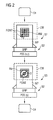
- FIG. 2 shows a flow chart of a first program which may be comprised by the software SW as a first embodiment.
- the program starts in a step S1.
- the master part MP is arranged in the gripper GRIP.
- a dashed box indicates as the camera window CW what is seen by the camera CAM and thus what is visible in the camera image IMG.
- step S2 the positioning unit POS is controlled essentially with respect to the X- and Z-direction to move the pointer POINT from a unaligned starting position P0 to an aligned position P with respect to the reference marker RM.
- the master part MP is moved such with respect to first body that the pointer POINT is centered on the reference marker RM.
- the positioning unit POS is controlled with the camera image IMG as a feedback, which allows for very precise positioning.
- a step S3 may be provided additionally for aligning a distance between the master part MP and the first body B1 and a focus of the laser beam LB and particularly of the pointer POINT.
- the positioning unit POS may be controlled essentially with respect to the Y-direction.
- the focusing unit FOC may be controlled to focus the laser beam LB on the master part MP.
- the positioning unit POS and/or the focusing unit FOC are controlled dependent on a diameter D of the pointer POINT visible in the camera image IMG.
- the positioning unit POS and/or the focusing unit FOC are controlled to minimize the diameter D. With the pointer POINT having the minimal diameter D it is assumed that the master part MP is in focus.
- the process performed in the step S3 may also be called autofocusing.
- the program ends in a step S4 in which, for example, the master part MP may be unloaded from the gripper GRIP so that other parts may be processed, for example welded.
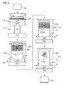
- FIG. 3 shows a flow chart of a second program which may be comprised by the software SW as a second embodiment.
- the program starts with a step S10.
- a runout check is performed for the gripper GRIP.
- the gripper GRIP is moved with the up/down positioning unit UD such that it is visible within the camera window CW.
- the gripper GRIP is controlled to rotate by the servo unit SERV and the gripper GRIP is checked for the runout preferably dependent on the camera image IMG. If the runout of the gripper GRIP is detected, the program preferably ends.
- a runout check is performed for the master part MP.
- the master part MP is loaded in the gripper GRIP and the servo unit SERV preferably is controlled to rotate the master part MP within the camera window CW.
- the master part MP is checked for the runout preferably dependent on the camera image IMG. If the runout of the master part MP is detected, the program preferably ends.
- Steps S13, S14 and S15 essentially are the same as steps S2, S3 and S4, respectively, of the first embodiment.
- FIG. 4 shows a diagram.
- An operator OP of the system preferably loads and unloads the master part MP into or from the gripper GRIP and controls the control unit PLC, for example by activating the positioning and autofocusing process explained above.
- the control unit PLC is coupled with the pointing unit and the positioning unit POS and the gripper GRIP and preferably also with the servo unit SERV for control of these as explained above.
- the camera CAM sends its camera image IMG to the control unit PLC.
- the software SW running on the control unit PLC processes the the camera image IMG and controls the pointing device, the positioning unit POS, the gripper GRIP and preferably also the servo unit SERV over the control unit PLC.
- the processing of the part and/or a result of the processing may be monitored and checked. By this, scrap can easily be identified. For this online monitoring and checking, only an amendment of the software SW is necessary, which may be provided as a software upgrade.
Landscapes
- Physics & Mathematics (AREA)
- Optics & Photonics (AREA)
- Engineering & Computer Science (AREA)
- Plasma & Fusion (AREA)
- Mechanical Engineering (AREA)
- Laser Beam Processing (AREA)
Abstract
Description
- Method, device and system for positioning a first body and a part fixed to a second body with respect to each other
- The invention relates to a method, a device and a system comprising the device for positioning a first body and a part fixed to a second body with respect to each other and particularly relates to a positioning of a part in a gripper with respect to a laser head in a laser welding system.
- With laser welding systems precise welding of parts is possible. However, for this, a position of the part to be processed with respect to the laser head must be very precise. The laser head is therefore positioned manually by an operator. For mass production, this is inefficient.
- The object of the invention is to provide a method, a device and a system for positioning a first body and a part fixed to a second body with respect to each other that allows for automatic precise positioning.
- This object is achieved with the features of the independent claims. Preferred embodiments are characterized in the dependent claims.
- According to a first aspect the invention is characterized by a method and a corresponding device for positioning a first body and a part fixed to a second body with respect to each other. The method comprises receiving a camera image of a master part used as the part. The master part has a reference marker and is fixed to the second body such that the reference marker is visible in the camera image and the master part is moveable along with the second body. It further comprises determining a first position of a pointer on the master part dependent on the camera image. The pointer is representative for a current position of the first body and is visible in the camera image. The method further comprises controlling a positioning unit to move the pointer from the first position to a predetermined second position with respect to the reference marker dependent on the camera image. The positioning unit is coupled with the first body for moving the first body and the pointer or is coupled with the second body for moving the second body and the master part. The device is adapted to perform this method.
- The advantage is that this allows for a fast, precise, reliable and reproducible positioning of the part with respect to the first body and thus allows for a precise processing of a part that is fixed to the second body replacing the master part. The part may then be processed with high precision, for example with a tolerance of some ten micrometers, about a micrometer or even less than a micrometer. It is further possible that the part to process has the reference marker and thus acts as the master part. This allows for an exceptionally precise processing of the part.
- According to a preferred embodiment, the method comprises controlling the positioning unit to move the first or the second body or controlling a focusing unit adapted for focusing the pointer to minimize a diameter of the pointer on the master part. By this, a distance of the part with respect to the first body and the focus of the pointer can be adjusted precisely to align the distance and the focus. This allows for a precise processing of the part.
- According to a further preferred embodiment, the second body comprises a pointing unit that comprises a laser and the pointer is a reflection of a laser beam emitted by the pointing unit. This is simple, precise and reliable.
- In this respect, it is advantageous if the first body is a laser head of a laser welding system. This allows for precise and reliable welding of parts. Further, the laser beam creating the pointer may preferably emitted by the laser head through the same optical path as a laser beam used for welding. This allows for aligning the laser beam used for welding very precisely through aligning the laser beam used for creating the pointer.
- According to a further preferred embodiment, prior to the controlling of the positioning unit to move the pointer from the first position to the predetermined second position the master part is checked for a runout. This enables very precise positioning, if such runouts are detected and corrected before the controlling of the positioning unit.
- According to a further preferred embodiment, prior to the controlling of the positioning unit to move the pointer from the first position to the predetermined second position or prior to checking the master part for a runout a gripper is checked for a runout. The gripper is comprised by the second body and is adapted to fix the part to the second body. This enables very precise positioning, if such runouts are detected and corrected before the positioning.
- According to a further preferred embodiment, the method comprises receiving a camera image of the part that is being fixed to the first body instead of the master part after the positioning of the master part is finished during and/or after processing of the part. The method further comprises monitoring the processing and/or checking a result of the processing dependent on the camera image of the part. By this, scrap can be identified easily during the processing or directly after the processing of the part. A high quality of the resulting processed parts can be achieved.
- According to a second aspect the invention is characterized by a system. The system comprises a first body with a pointing unit for providing a pointer and a camera. The pointer is representative for a current position of the first body and is visible in a camera image of the camera. The system further comprises a second body with a gripper for fixing a part to the second body. The system further comprises a positioning unit being coupled with the first body for moving the first body and the pointer or being coupled with the second body for moving the second body and the part. The system further comprises a device according to the first aspect of the invention. The advantages of the first aspect of the invention and the advantages of its preferred embodiments also apply to the second aspect accordingly.
- In a preferred embodiment of the second aspect, the system is a laser welding system. Precise laser welding of parts is thus possible.
- In the following, embodiments of the invention are illustrated with reference to the schematic drawings.
- The figures are illustrating:
-
FIG. 1 , a system, -
FIG. 2 , a flow chart of a first program, -
FIG. 3 , a flow chart of a second program and -
FIG. 4 , a diagram. - Elements of same construction or function are provided with the same reference signs throughout all figures.
- A system comprises a first body B1 and a second body B2 (
FIG. 1 ). The first and the second body B1, B2 preferably are arranged on a basement BAS. Preferably, the system is designed as a laser welding system comprising a welding chamber WC. The first body B1 preferably comprises a laser head LH or is designed as the laser head LH. The laser head LH preferably comprises a collimator COL and a laser or an optical fiber OF that is coupled with a laser and a focusing unit FOC for focusing a laser beam LB. The laser beam LB preferably is a high power laser beam used for welding a part that is arranged in the welding chamber WC. - The first body B1 comprises a vision system VIS comprising a camera CAM. The first body B1 preferably further comprises a pointing unit for providing a pointer POINT. The pointing unit preferably comprises a laser which emits a low power laser beam LB. The pointing unit may be comprised by the laser that generates the high power laser beam LB. Preferably, the high power laser beam LB for welding and the low power laser beam LB for pointing are emitted through essentially the same optical path, that is for example through the optical fiber OF, the collimator COL and the focusing unit FOC on the part arranged in the welding chamber. However, the pointing unit may also be designed differently.
- The second body B2 comprises a gripper GRIP which is adapted to hold and fix a part or master part MP to the second body B2. The gripper GRIP preferably is arranged such that the part or master part MP is arranged in the welding chamber WC for welding if it is loaded to the gripper GRIP. Preferably, the second body B2 further comprises a servo unit SERV adapted to rotating the part or master part MP in the welding chamber WC around a longitudinal axis, which is parallel to a direction depicted in
FIG. 1 as Z. The second body B2 preferably comprises an up/down positioning unit UD for moving the part or master part MP up and down along the Z-direction. Further, the second body comprises a positioning unit POS for precisely moving the gripper GRIP and thus also the part or master part MP in an X-, Y- and the Z-direction, preferably with a resolution of some ten micrometers, about one micrometer or even less than one micrometer. Alternatively or additionally, the positioning unit POS may be comprised by the first body B1 for moving the laser head LH and particularly the pointing unit in the X-, Y- and Z-direction accordingly. - For controlling the positioning unit POS and preferably also for controlling the gripper GRIP and/or the servo unit SERV and/or the up/down positioning unit UD, a control unit PLC is provided. The control unit PLC may also be called a device for positioning the first body and the part or master part MP fixed to the second body with respect to each other. The control unit PLC may preferably be designed as a programmable logic controller or as a computer. The control unit PLC is adapted to execute a software SW, such as a computer program, for controlling the positioning unit POS and preferably also for controlling the gripper GRIP and/or the servo unit SERV and/or the up/down positioning unit UD and for receiving and preferably processing of a camera image IMG from the camera CAM.
- The camera CAM is arranged such that the camera image IMG shows the part or master part MP held in the gripper GRIP and, particularly in case the master part MP is held in the gripper GRIP, shows a reference marker RM and the pointer POINT. The reference marker RM preferably is designed as grid of lines clearly visible in the camera image IMG. However, the reference marker RM can be designed differently. Preferably, only the master part RM, which is not intended for further processing such as welding, has the reference marker RM. But it is also possible that other parts, that is parts intended for further processing such as welding, have the reference marker RM.
-
FIG. 2 shows a flow chart of a first program which may be comprised by the software SW as a first embodiment. The program starts in a step S1. In the step S1, for example, the master part MP is arranged in the gripper GRIP. Further, it may be necessary to control the servo unit SERV and/or the up/down positioning unit UD to bring the reference marker RM at least roughly in a predefined position within a camera window CW. In a step S2 and also in other steps, a dashed box indicates as the camera window CW what is seen by the camera CAM and thus what is visible in the camera image IMG. In step S2, then, the positioning unit POS is controlled essentially with respect to the X- and Z-direction to move the pointer POINT from a unaligned starting position P0 to an aligned position P with respect to the reference marker RM. For example, the master part MP is moved such with respect to first body that the pointer POINT is centered on the reference marker RM. In other words, the positioning unit POS is controlled with the camera image IMG as a feedback, which allows for very precise positioning. - A step S3 may be provided additionally for aligning a distance between the master part MP and the first body B1 and a focus of the laser beam LB and particularly of the pointer POINT. For this, the positioning unit POS may be controlled essentially with respect to the Y-direction. Alternatively or additionally, the focusing unit FOC may be controlled to focus the laser beam LB on the master part MP. Preferably, the positioning unit POS and/or the focusing unit FOC are controlled dependent on a diameter D of the pointer POINT visible in the camera image IMG. Particularly, the positioning unit POS and/or the focusing unit FOC are controlled to minimize the diameter D. With the pointer POINT having the minimal diameter D it is assumed that the master part MP is in focus. The process performed in the step S3 may also be called autofocusing.
- The program ends in a step S4 in which, for example, the master part MP may be unloaded from the gripper GRIP so that other parts may be processed, for example welded.
-
FIG. 3 shows a flow chart of a second program which may be comprised by the software SW as a second embodiment. The program starts with a step S10. In a step S11, a runout check is performed for the gripper GRIP. Preferably, the gripper GRIP is moved with the up/down positioning unit UD such that it is visible within the camera window CW. Preferably, the gripper GRIP is controlled to rotate by the servo unit SERV and the gripper GRIP is checked for the runout preferably dependent on the camera image IMG. If the runout of the gripper GRIP is detected, the program preferably ends. - In a step S12, a runout check is performed for the master part MP. The master part MP is loaded in the gripper GRIP and the servo unit SERV preferably is controlled to rotate the master part MP within the camera window CW. The master part MP is checked for the runout preferably dependent on the camera image IMG. If the runout of the master part MP is detected, the program preferably ends.
- Steps S13, S14 and S15 essentially are the same as steps S2, S3 and S4, respectively, of the first embodiment.
-
FIG. 4 shows a diagram. An operator OP of the system preferably loads and unloads the master part MP into or from the gripper GRIP and controls the control unit PLC, for example by activating the positioning and autofocusing process explained above. The control unit PLC is coupled with the pointing unit and the positioning unit POS and the gripper GRIP and preferably also with the servo unit SERV for control of these as explained above. The camera CAM sends its camera image IMG to the control unit PLC. The software SW running on the control unit PLC processes the the camera image IMG and controls the pointing device, the positioning unit POS, the gripper GRIP and preferably also the servo unit SERV over the control unit PLC. By this, a very precise feedback controlled positioning and autofocusing of parts with respect to the laser head LH is possile automatically. - Because of the part being visible in the camera image IMG, the processing of the part and/or a result of the processing may be monitored and checked. By this, scrap can easily be identified. For this online monitoring and checking, only an amendment of the software SW is necessary, which may be provided as a software upgrade.
Claims (10)
- Method for positioning a first body (B1) and a part fixed to a second body (B2) with respect to each other, comprising- receiving a camera image (IMG) of a master part (MP) used as the part, the master part (MP) having a reference marker (RM) and being fixed to the second body (B2) such that the reference marker (RM) is visible in the camera image (IMG) and the master part (MP) is moveable along with the second body (B2),- determining a first position of a pointer (POINT) on the master part (MP) dependent on the camera image (IMG), the pointer (POINT) being representative for a current position of the first body (B1) and being visible in the camera image (IMG), and- controlling a positioning unit (POS) to move the pointer (POINT) from the first position to a predetermined second position with respect to the reference marker (RM) dependent on the camera image (IMG), the positioning unit (POS) being coupled with the first body (B1) for moving the first body (B1) and the pointer (POINT) or being coupled with the second body (B2) for moving the second body (B2) and the master part (MP).
- Method according to claim 1, comprising controlling the positioning unit (POS) to move the first or the second body (B1, B2) or controlling a focusing unit (FOC) adapted for focusing the pointer (POINT) to minimize a diameter (D) of the pointer (POINT) on the master part (MP).
- Method according to any one of claims 1 or 2, wherein the second body (B2) comprises a pointing unit that comprises a laser and the pointer (POINT) is a reflection of a laser beam emitted by the pointing unit.
- Method according to claim 3, wherein the first body (B1) is a laser head (LH) of a laser welding system.
- Method according to any one of claims 1 to 4, wherein prior to the controlling of the positioning unit (POS) to move the pointer (POINT) from the first position to the predetermined second position the master part (MP) is checked for a runout.
- Method according to any one of claims 1 to 5, wherein prior to the controlling of the positioning unit (POS) to move the pointer (POINT) from the first position to the predetermined second position or prior to checking the master part (MP) for a runout a gripper (GRIP) is checked for a runout, the gripper (GRIP) being comprised by the second body (B2) and being adapted to fix the part to the second body (B2).
- Method according to any one of claims 1 to 6, comprising- receiving a camera image (IMG) of the part that is being fixed to the first body (B1) instead of the master part (MP) after the positioning of the master part (MP) is finished during and/or after processing of the part and- monitoring the processing and/or checking a result of the processing dependent on the camera image (IMG) of the part.
- Device for positioning a first body (B1) and a part fixed to a second body (B2) with respect to each other, the device being adapted to- receive a camera image (IMG) of a master part (MP) used as the part, the master part (MP) having a reference marker (RM) and being fixed to the second body (B2) such that the reference marker (RM) is visible in the camera image (IMG) and the master part (MP) is moveable along with the second body (B2),- determine a first position of a pointer (POINT) on the master part (MP) dependent on the camera image (IMG), the pointer (POINT) being representative for a current position of the first body (B1) and being visible in the camera image (IMG), and- control a positioning unit (POS) to move the pointer (POINT) from the first position to a predetermined second position with respect to the reference marker (RM) dependent on the camera image (IMG), the positioning unit (POS) being coupled with the first body (B1) for moving the first body (B1) and the pointer (POINT) or being coupled with the second body (B2) for moving the second body (B2) and the master part (MP).
- System comprising- a first body (B1) with a pointing unit for providing a pointer (POINT) and a camera (CAM), the pointer (POINT) being representative for a current position of the first body (B1) and being visible in a camera image (IMG) of the camera (CAM),- a second body (B2) with a gripper (GRIP) for fixing a part to the second body (B2),- a positioning unit (POS) being coupled with the first body (B1) for moving the first body (B1) and the pointer (POINT) or being coupled with the second body (B2) for moving the second body (B2) and the part and- a device according to claim 8.
- System according to claim 9, wherein the system is a laser welding system.
Priority Applications (2)
| Application Number | Priority Date | Filing Date | Title |
|---|---|---|---|
| EP08022494.2A EP2202027B1 (en) | 2008-12-29 | 2008-12-29 | Method, device and system for positioning a first body and a part fixed to a second body with respect to each other |
| US12/648,464 US8487990B2 (en) | 2008-12-29 | 2009-12-29 | Method, device and system for positioning a first body and a part fixed to a second body with respect to each other |
Applications Claiming Priority (1)
| Application Number | Priority Date | Filing Date | Title |
|---|---|---|---|
| EP08022494.2A EP2202027B1 (en) | 2008-12-29 | 2008-12-29 | Method, device and system for positioning a first body and a part fixed to a second body with respect to each other |
Publications (2)
| Publication Number | Publication Date |
|---|---|
| EP2202027A1 true EP2202027A1 (en) | 2010-06-30 |
| EP2202027B1 EP2202027B1 (en) | 2016-07-13 |
Family
ID=40561728
Family Applications (1)
| Application Number | Title | Priority Date | Filing Date |
|---|---|---|---|
| EP08022494.2A Not-in-force EP2202027B1 (en) | 2008-12-29 | 2008-12-29 | Method, device and system for positioning a first body and a part fixed to a second body with respect to each other |
Country Status (2)
| Country | Link |
|---|---|
| US (1) | US8487990B2 (en) |
| EP (1) | EP2202027B1 (en) |
Citations (2)
| Publication number | Priority date | Publication date | Assignee | Title |
|---|---|---|---|---|
| DE202005010715U1 (en) * | 2005-07-06 | 2005-09-22 | Sikora Gmbh | Adjusting device for a flying laser welding head having a cassette receiver and an adjustable laser beam useful in sheet welding operations |
| US20060055928A1 (en) * | 2004-09-15 | 2006-03-16 | Taiwan Semiconductor Manufacturing Co., Ltd. | Test device and method for laser alignment calibration |
Family Cites Families (2)
| Publication number | Priority date | Publication date | Assignee | Title |
|---|---|---|---|---|
| JP2866831B2 (en) * | 1996-08-30 | 1999-03-08 | 株式会社アドバンテスト | Laser processing equipment positioning method |
| US7067763B2 (en) * | 2002-05-17 | 2006-06-27 | Gsi Group Corporation | High speed, laser-based marking method and system for producing machine readable marks on workpieces and semiconductor devices with reduced subsurface damage produced thereby |
-
2008
- 2008-12-29 EP EP08022494.2A patent/EP2202027B1/en not_active Not-in-force
-
2009
- 2009-12-29 US US12/648,464 patent/US8487990B2/en not_active Expired - Fee Related
Patent Citations (2)
| Publication number | Priority date | Publication date | Assignee | Title |
|---|---|---|---|---|
| US20060055928A1 (en) * | 2004-09-15 | 2006-03-16 | Taiwan Semiconductor Manufacturing Co., Ltd. | Test device and method for laser alignment calibration |
| DE202005010715U1 (en) * | 2005-07-06 | 2005-09-22 | Sikora Gmbh | Adjusting device for a flying laser welding head having a cassette receiver and an adjustable laser beam useful in sheet welding operations |
Also Published As
| Publication number | Publication date |
|---|---|
| US20100165098A1 (en) | 2010-07-01 |
| US8487990B2 (en) | 2013-07-16 |
| EP2202027B1 (en) | 2016-07-13 |
Similar Documents
| Publication | Publication Date | Title |
|---|---|---|
| US6688783B2 (en) | Method of fabricating an optical module including a lens attached to a platform of the optical module | |
| US6351483B1 (en) | Laser optical axis correcting method | |
| CN112846485B (en) | Laser processing monitoring method and device and laser processing equipment | |
| RU2698238C2 (en) | Apparatus for applying rivets to workpiece, comprising device for monitoring and correcting position of riveting working device relative to said workpiece | |
| CN111452047A (en) | Robot tool deviation correction method, robot control device and system | |
| US20170173715A1 (en) | Wire electric discharge machine | |
| EP3358429B1 (en) | System and method for precisely drilling matched hole patterns using surface mapped features | |
| KR20060097043A (en) | Stage device | |
| JP2020528828A (en) | Methods for processing laser materials, and laser processing machines | |
| JP2006330210A (en) | Method and device for collimating lens | |
| US8487990B2 (en) | Method, device and system for positioning a first body and a part fixed to a second body with respect to each other | |
| CN111595440B (en) | Automatic optical fiber butting and clamping mechanism for target switching of spectrometer and method thereof | |
| EP1252968A1 (en) | Tooling fixture building process | |
| JP2012035281A (en) | System for detection of laser beam machining | |
| KR102738943B1 (en) | Method for positioning a test substrate, probes and a test unit relative to each other and a tester for carrying out said method | |
| EP4202397B1 (en) | Actively select lenses for camera focus processes | |
| JP2009025640A (en) | Method and device for adjusting optical axis of optical component, optical component adjusted by optical axis adjusting method, and manufacturing method of optical component | |
| EP2732899A1 (en) | Method and apparatus for soldering a copper wire on a terminal, particularly for soldering the end of the winding wire of electric coils on a bronze terminal | |
| JP2003098390A (en) | Method and device for adjusting optical axis | |
| JP2002120079A (en) | Laser processing apparatus and laser processing method | |
| EP4202396B1 (en) | Actively select lenses for camera focus processes | |
| KR102890800B1 (en) | Processing system including magnetic jig | |
| JP2008209537A (en) | Lens centering device and lens centering method | |
| KR102182400B1 (en) | Method for annealing a specific region of a workpiece using a laser beam | |
| JP2008032524A (en) | Laser processing apparatus and focus detection method of laser beam for measurement |
Legal Events
| Date | Code | Title | Description |
|---|---|---|---|
| PUAI | Public reference made under article 153(3) epc to a published international application that has entered the european phase |
Free format text: ORIGINAL CODE: 0009012 |
|
| AK | Designated contracting states |
Kind code of ref document: A1 Designated state(s): AT BE BG CH CY CZ DE DK EE ES FI FR GB GR HR HU IE IS IT LI LT LU LV MC MT NL NO PL PT RO SE SI SK TR |
|
| AX | Request for extension of the european patent |
Extension state: AL BA MK RS |
|
| 17P | Request for examination filed |
Effective date: 20101230 |
|
| AKX | Designation fees paid |
Designated state(s): AT BE BG CH CY CZ DE DK EE ES FI FR GB GR HR HU IE IS IT LI LT LU LV MC MT NL NO PL PT RO SE SI SK TR |
|
| 17Q | First examination report despatched |
Effective date: 20110406 |
|
| GRAP | Despatch of communication of intention to grant a patent |
Free format text: ORIGINAL CODE: EPIDOSNIGR1 |
|
| INTG | Intention to grant announced |
Effective date: 20160210 |
|
| GRAS | Grant fee paid |
Free format text: ORIGINAL CODE: EPIDOSNIGR3 |
|
| GRAA | (expected) grant |
Free format text: ORIGINAL CODE: 0009210 |
|
| AK | Designated contracting states |
Kind code of ref document: B1 Designated state(s): AT BE BG CH CY CZ DE DK EE ES FI FR GB GR HR HU IE IS IT LI LT LU LV MC MT NL NO PL PT RO SE SI SK TR |
|
| REG | Reference to a national code |
Ref country code: GB Ref legal event code: FG4D |
|
| REG | Reference to a national code |
Ref country code: AT Ref legal event code: REF Ref document number: 811896 Country of ref document: AT Kind code of ref document: T Effective date: 20160715 Ref country code: CH Ref legal event code: EP |
|
| REG | Reference to a national code |
Ref country code: IE Ref legal event code: FG4D |
|
| REG | Reference to a national code |
Ref country code: DE Ref legal event code: R096 Ref document number: 602008045055 Country of ref document: DE |
|
| REG | Reference to a national code |
Ref country code: LT Ref legal event code: MG4D |
|
| REG | Reference to a national code |
Ref country code: NL Ref legal event code: MP Effective date: 20160713 |
|
| REG | Reference to a national code |
Ref country code: AT Ref legal event code: MK05 Ref document number: 811896 Country of ref document: AT Kind code of ref document: T Effective date: 20160713 |
|
| REG | Reference to a national code |
Ref country code: FR Ref legal event code: PLFP Year of fee payment: 9 |
|
| PG25 | Lapsed in a contracting state [announced via postgrant information from national office to epo] |
Ref country code: LT Free format text: LAPSE BECAUSE OF FAILURE TO SUBMIT A TRANSLATION OF THE DESCRIPTION OR TO PAY THE FEE WITHIN THE PRESCRIBED TIME-LIMIT Effective date: 20160713 Ref country code: FI Free format text: LAPSE BECAUSE OF FAILURE TO SUBMIT A TRANSLATION OF THE DESCRIPTION OR TO PAY THE FEE WITHIN THE PRESCRIBED TIME-LIMIT Effective date: 20160713 Ref country code: NL Free format text: LAPSE BECAUSE OF FAILURE TO SUBMIT A TRANSLATION OF THE DESCRIPTION OR TO PAY THE FEE WITHIN THE PRESCRIBED TIME-LIMIT Effective date: 20160713 Ref country code: IS Free format text: LAPSE BECAUSE OF FAILURE TO SUBMIT A TRANSLATION OF THE DESCRIPTION OR TO PAY THE FEE WITHIN THE PRESCRIBED TIME-LIMIT Effective date: 20161113 Ref country code: NO Free format text: LAPSE BECAUSE OF FAILURE TO SUBMIT A TRANSLATION OF THE DESCRIPTION OR TO PAY THE FEE WITHIN THE PRESCRIBED TIME-LIMIT Effective date: 20161013 Ref country code: HR Free format text: LAPSE BECAUSE OF FAILURE TO SUBMIT A TRANSLATION OF THE DESCRIPTION OR TO PAY THE FEE WITHIN THE PRESCRIBED TIME-LIMIT Effective date: 20160713 |
|
| PG25 | Lapsed in a contracting state [announced via postgrant information from national office to epo] |
Ref country code: PT Free format text: LAPSE BECAUSE OF FAILURE TO SUBMIT A TRANSLATION OF THE DESCRIPTION OR TO PAY THE FEE WITHIN THE PRESCRIBED TIME-LIMIT Effective date: 20161114 Ref country code: LV Free format text: LAPSE BECAUSE OF FAILURE TO SUBMIT A TRANSLATION OF THE DESCRIPTION OR TO PAY THE FEE WITHIN THE PRESCRIBED TIME-LIMIT Effective date: 20160713 Ref country code: BE Free format text: LAPSE BECAUSE OF FAILURE TO SUBMIT A TRANSLATION OF THE DESCRIPTION OR TO PAY THE FEE WITHIN THE PRESCRIBED TIME-LIMIT Effective date: 20160713 Ref country code: SE Free format text: LAPSE BECAUSE OF FAILURE TO SUBMIT A TRANSLATION OF THE DESCRIPTION OR TO PAY THE FEE WITHIN THE PRESCRIBED TIME-LIMIT Effective date: 20160713 Ref country code: AT Free format text: LAPSE BECAUSE OF FAILURE TO SUBMIT A TRANSLATION OF THE DESCRIPTION OR TO PAY THE FEE WITHIN THE PRESCRIBED TIME-LIMIT Effective date: 20160713 Ref country code: GR Free format text: LAPSE BECAUSE OF FAILURE TO SUBMIT A TRANSLATION OF THE DESCRIPTION OR TO PAY THE FEE WITHIN THE PRESCRIBED TIME-LIMIT Effective date: 20161014 Ref country code: PL Free format text: LAPSE BECAUSE OF FAILURE TO SUBMIT A TRANSLATION OF THE DESCRIPTION OR TO PAY THE FEE WITHIN THE PRESCRIBED TIME-LIMIT Effective date: 20160713 Ref country code: ES Free format text: LAPSE BECAUSE OF FAILURE TO SUBMIT A TRANSLATION OF THE DESCRIPTION OR TO PAY THE FEE WITHIN THE PRESCRIBED TIME-LIMIT Effective date: 20160713 |
|
| REG | Reference to a national code |
Ref country code: DE Ref legal event code: R097 Ref document number: 602008045055 Country of ref document: DE |
|
| PG25 | Lapsed in a contracting state [announced via postgrant information from national office to epo] |
Ref country code: RO Free format text: LAPSE BECAUSE OF FAILURE TO SUBMIT A TRANSLATION OF THE DESCRIPTION OR TO PAY THE FEE WITHIN THE PRESCRIBED TIME-LIMIT Effective date: 20160713 Ref country code: EE Free format text: LAPSE BECAUSE OF FAILURE TO SUBMIT A TRANSLATION OF THE DESCRIPTION OR TO PAY THE FEE WITHIN THE PRESCRIBED TIME-LIMIT Effective date: 20160713 |
|
| PLBE | No opposition filed within time limit |
Free format text: ORIGINAL CODE: 0009261 |
|
| STAA | Information on the status of an ep patent application or granted ep patent |
Free format text: STATUS: NO OPPOSITION FILED WITHIN TIME LIMIT |
|
| PG25 | Lapsed in a contracting state [announced via postgrant information from national office to epo] |
Ref country code: SK Free format text: LAPSE BECAUSE OF FAILURE TO SUBMIT A TRANSLATION OF THE DESCRIPTION OR TO PAY THE FEE WITHIN THE PRESCRIBED TIME-LIMIT Effective date: 20160713 Ref country code: DK Free format text: LAPSE BECAUSE OF FAILURE TO SUBMIT A TRANSLATION OF THE DESCRIPTION OR TO PAY THE FEE WITHIN THE PRESCRIBED TIME-LIMIT Effective date: 20160713 Ref country code: BG Free format text: LAPSE BECAUSE OF FAILURE TO SUBMIT A TRANSLATION OF THE DESCRIPTION OR TO PAY THE FEE WITHIN THE PRESCRIBED TIME-LIMIT Effective date: 20161013 Ref country code: CZ Free format text: LAPSE BECAUSE OF FAILURE TO SUBMIT A TRANSLATION OF THE DESCRIPTION OR TO PAY THE FEE WITHIN THE PRESCRIBED TIME-LIMIT Effective date: 20160713 |
|
| 26N | No opposition filed |
Effective date: 20170418 |
|
| REG | Reference to a national code |
Ref country code: CH Ref legal event code: PL |
|
| GBPC | Gb: european patent ceased through non-payment of renewal fee |
Effective date: 20161229 |
|
| PG25 | Lapsed in a contracting state [announced via postgrant information from national office to epo] |
Ref country code: SI Free format text: LAPSE BECAUSE OF FAILURE TO SUBMIT A TRANSLATION OF THE DESCRIPTION OR TO PAY THE FEE WITHIN THE PRESCRIBED TIME-LIMIT Effective date: 20160713 |
|
| PG25 | Lapsed in a contracting state [announced via postgrant information from national office to epo] |
Ref country code: MC Free format text: LAPSE BECAUSE OF FAILURE TO SUBMIT A TRANSLATION OF THE DESCRIPTION OR TO PAY THE FEE WITHIN THE PRESCRIBED TIME-LIMIT Effective date: 20160713 |
|
| REG | Reference to a national code |
Ref country code: IE Ref legal event code: MM4A |
|
| PG25 | Lapsed in a contracting state [announced via postgrant information from national office to epo] |
Ref country code: CH Free format text: LAPSE BECAUSE OF NON-PAYMENT OF DUE FEES Effective date: 20161231 Ref country code: LI Free format text: LAPSE BECAUSE OF NON-PAYMENT OF DUE FEES Effective date: 20161231 Ref country code: LU Free format text: LAPSE BECAUSE OF NON-PAYMENT OF DUE FEES Effective date: 20161229 |
|
| PG25 | Lapsed in a contracting state [announced via postgrant information from national office to epo] |
Ref country code: IE Free format text: LAPSE BECAUSE OF NON-PAYMENT OF DUE FEES Effective date: 20161229 Ref country code: GB Free format text: LAPSE BECAUSE OF NON-PAYMENT OF DUE FEES Effective date: 20161229 |
|
| REG | Reference to a national code |
Ref country code: FR Ref legal event code: PLFP Year of fee payment: 10 |
|
| PG25 | Lapsed in a contracting state [announced via postgrant information from national office to epo] |
Ref country code: CY Free format text: LAPSE BECAUSE OF FAILURE TO SUBMIT A TRANSLATION OF THE DESCRIPTION OR TO PAY THE FEE WITHIN THE PRESCRIBED TIME-LIMIT Effective date: 20160713 Ref country code: HU Free format text: LAPSE BECAUSE OF FAILURE TO SUBMIT A TRANSLATION OF THE DESCRIPTION OR TO PAY THE FEE WITHIN THE PRESCRIBED TIME-LIMIT; INVALID AB INITIO Effective date: 20081229 |
|
| PG25 | Lapsed in a contracting state [announced via postgrant information from national office to epo] |
Ref country code: TR Free format text: LAPSE BECAUSE OF FAILURE TO SUBMIT A TRANSLATION OF THE DESCRIPTION OR TO PAY THE FEE WITHIN THE PRESCRIBED TIME-LIMIT Effective date: 20160713 |
|
| PG25 | Lapsed in a contracting state [announced via postgrant information from national office to epo] |
Ref country code: MT Free format text: LAPSE BECAUSE OF NON-PAYMENT OF DUE FEES Effective date: 20161229 |
|
| PGFP | Annual fee paid to national office [announced via postgrant information from national office to epo] |
Ref country code: FR Payment date: 20181220 Year of fee payment: 11 |
|
| PGFP | Annual fee paid to national office [announced via postgrant information from national office to epo] |
Ref country code: IT Payment date: 20181220 Year of fee payment: 11 Ref country code: DE Payment date: 20181231 Year of fee payment: 11 |
|
| REG | Reference to a national code |
Ref country code: DE Ref legal event code: R081 Ref document number: 602008045055 Country of ref document: DE Owner name: VITESCO TECHNOLOGIES GMBH, DE Free format text: FORMER OWNER: CONTINENTAL AUTOMOTIVE GMBH, 30165 HANNOVER, DE |
|
| REG | Reference to a national code |
Ref country code: DE Ref legal event code: R119 Ref document number: 602008045055 Country of ref document: DE |
|
| PG25 | Lapsed in a contracting state [announced via postgrant information from national office to epo] |
Ref country code: IT Free format text: LAPSE BECAUSE OF NON-PAYMENT OF DUE FEES Effective date: 20191229 Ref country code: FR Free format text: LAPSE BECAUSE OF NON-PAYMENT OF DUE FEES Effective date: 20191231 Ref country code: DE Free format text: LAPSE BECAUSE OF NON-PAYMENT OF DUE FEES Effective date: 20200701 |