EP2201974A1 - Medication delivery device - Google Patents
Medication delivery device Download PDFInfo
- Publication number
- EP2201974A1 EP2201974A1 EP08022318A EP08022318A EP2201974A1 EP 2201974 A1 EP2201974 A1 EP 2201974A1 EP 08022318 A EP08022318 A EP 08022318A EP 08022318 A EP08022318 A EP 08022318A EP 2201974 A1 EP2201974 A1 EP 2201974A1
- Authority
- EP
- European Patent Office
- Prior art keywords
- cap
- orientation
- housing
- delivery device
- medication delivery
- Prior art date
- Legal status (The legal status is an assumption and is not a legal conclusion. Google has not performed a legal analysis and makes no representation as to the accuracy of the status listed.)
- Ceased
Links
Images

Classifications
-
- A—HUMAN NECESSITIES
- A61—MEDICAL OR VETERINARY SCIENCE; HYGIENE
- A61M—DEVICES FOR INTRODUCING MEDIA INTO, OR ONTO, THE BODY; DEVICES FOR TRANSDUCING BODY MEDIA OR FOR TAKING MEDIA FROM THE BODY; DEVICES FOR PRODUCING OR ENDING SLEEP OR STUPOR
- A61M5/00—Devices for bringing media into the body in a subcutaneous, intra-vascular or intramuscular way; Accessories therefor, e.g. filling or cleaning devices, arm rests
- A61M5/178—Syringes
- A61M5/31—Details
- A61M5/32—Needles; Details of needles pertaining to their connection with syringe or hub; Accessories for bringing the needle into, or holding the needle on, the body; Devices for protection of needles
- A61M5/3205—Apparatus for removing or disposing of used needles or syringes, e.g. containers; Means for protection against accidental injuries from used needles
- A61M5/321—Means for protection against accidental injuries by used needles
- A61M5/3213—Caps placed axially onto the needle, e.g. equipped with finger protection guards
-
- A—HUMAN NECESSITIES
- A61—MEDICAL OR VETERINARY SCIENCE; HYGIENE
- A61M—DEVICES FOR INTRODUCING MEDIA INTO, OR ONTO, THE BODY; DEVICES FOR TRANSDUCING BODY MEDIA OR FOR TAKING MEDIA FROM THE BODY; DEVICES FOR PRODUCING OR ENDING SLEEP OR STUPOR
- A61M5/00—Devices for bringing media into the body in a subcutaneous, intra-vascular or intramuscular way; Accessories therefor, e.g. filling or cleaning devices, arm rests
- A61M5/178—Syringes
- A61M5/31—Details
- A61M5/3129—Syringe barrels
-
- A—HUMAN NECESSITIES
- A61—MEDICAL OR VETERINARY SCIENCE; HYGIENE
- A61M—DEVICES FOR INTRODUCING MEDIA INTO, OR ONTO, THE BODY; DEVICES FOR TRANSDUCING BODY MEDIA OR FOR TAKING MEDIA FROM THE BODY; DEVICES FOR PRODUCING OR ENDING SLEEP OR STUPOR
- A61M2205/00—General characteristics of the apparatus
- A61M2205/58—Means for facilitating use, e.g. by people with impaired vision
- A61M2205/583—Means for facilitating use, e.g. by people with impaired vision by visual feedback
-
- A—HUMAN NECESSITIES
- A61—MEDICAL OR VETERINARY SCIENCE; HYGIENE
- A61M—DEVICES FOR INTRODUCING MEDIA INTO, OR ONTO, THE BODY; DEVICES FOR TRANSDUCING BODY MEDIA OR FOR TAKING MEDIA FROM THE BODY; DEVICES FOR PRODUCING OR ENDING SLEEP OR STUPOR
- A61M2205/00—General characteristics of the apparatus
- A61M2205/60—General characteristics of the apparatus with identification means
Definitions
- This disclosure relates to a medication delivery device comprising a cap which can be attached onto a housing of the device.
- a cap which can be attached onto the housing only in a single orientation relative to the housing.
- the patent application EP 1923083 A1 discloses an injection device for setting and dispensing a fixed dose of a medicament.
- a removable cap can be releasably retained over a distal end of a cartridge retaining part.
- the patent EP 1007115 B1 discloses an injection device comprising a cap having a curved edge at its open end.
- a medication delivery device comprising a housing and a cap attachable onto the housing.
- the cap comprises at least one snap feature to attach the cap onto the housing and at least one orientation feature to define the orientation of the cap relative to the housing when the cap is attached onto the housing.
- At least one of the orientation features is located at a rigid part of the cap and at least one of the snap features is located at a less rigid part of the cap.
- the medication delivery device may be a pen-type injection device comprising a cartridge holder, wherein a cartridge comprising a medicament is retained.
- the cap is attachable onto the device such that it covers at least a part of the cartridge holder. This may be useful for protecting the cartridge, in particular when the cartridge is made of a breakable material like glass, or for protecting a needle unit at the distal end of the cartridge holder.
- the cap may comprise a window through which information provided by the cartridge or the cartridge holder is visible for the user. In the case that the information is visible only when the cap is attached in a certain orientation relative to the housing, the appropriate rotational orientation of the cap has to be ensured.
- the cap comprises at least one orientation feature.
- the housing comprises at least one mating orientation feature which interacts with at least one of the orientation features of the cap.
- a mating orientation feature on the housing is provided for each orientation feature on the cap.
- the cap might be attachable to the housing also in a wrong orientation.
- the cap may be forced onto the housing by a deformation at its flexible part where the orientation features are located and thereby, the orientation features bump over the mating orientation features of the housing.
- an orientation feature which is located at a rigid part of the cap such an elastic deformation and the resulting "bump over" may be prevented.
- At least one snap feature of the cap is located at a less rigid part of the cap.
- the housing comprises at least one mating snap feature which is engageable with at least one of the snap features of the cap.
- a certain elastic deformability of the cap may be required.
- a mating snap feature on the housing exists.
- the separate positioning of at least one orientation feature at a rigid part of the housing and of at least one snap feature at a less rigid part of the housing allows a reliable attachment of the cap at the right orientation relative to the housing.
- the medication delivery device may have a longitudinal axis.
- the cap may extend along the longitudinal axis, and the rigidity of the cap may vary along the longitudinal axis.
- the snap feature located at a less rigid part of the cap and the orientation feature located at a rigid part of the cap may have an offset along the longitudinal axis.
- the cap may comprise an open end and a closed end.
- at least one of the snap features is located near the open end of the cap and the orientation feature located at a rigid part of the cap is displaced from the snap feature in a direction towards the closed end of the cap.
- the cap is more rigid at its closed end than at its open end. This means that the cap can be more easily elastically deformed at its closed end than at its rigid end.
- the cap may be of a plastic material such as Polypropylen which may be easily deformable at the open end of the cap.
- the orientation feature comprises a rib.
- the rib may extend towards a longitudinal axis of the medication delivery device.
- the housing comprises a groove where the rib can engage.
- the cap may comprise several orientation features, wherein the orientation features in combination ensure that the cap is attached in the right orientation onto the housing.
- some of the orientation features may be located at a rigid part of the cap and others may be located at a less rigid part of the cap.
- the medication delivery device comprises a plurality of orientation features which have an angular offset around the longitudinal axis.
- these orientation features simultaneously interact with mating orientation features of the housing or with parts of the housing which prevent an attachment of the cap.
- a maximum counterforce can be achieved when a user tries to attach the cap in a wrong orientation.
- orientation features are located at the same axial position and at an angular offset relative to the longitudinal axis.
- the misplacement of the cap can be prevented efficiently even if a clearance between the inside diameter of the cap and the outside diameter of the housing exists. If only one orientation feature was present at a certain position at the longitudinal axis, there would be a high risk that the cap would be assembled on the housing off axis without the orientation feature preventing the full assembly. However, in the case that several orientation features, e. g. two diametrically opposed orientation features, are provided at a certain position, at least one orientation feature may prevent the assembly unless the correct orientation is found.
- orientation features are located at symmetric positions around the longitudinal axes of the device.
- the cap comprises three orientation features which are located at symmetric position around the longitudinal axes.
- the mating orientation features at the housing comprise a lead in to assist the assembly of the cap and the housing.
- the cap may be guided into the right orientation when a user tries to assemble the cap onto the housing in an orientation slightly deviating from the right orientation.
- the lead in may also allow a twisting off of the cap from the housing.
- the cap comprises at least one orientation feature which is located at the open end of the cap.
- the sum of the orientation features which are arranged at a rigid part of the cap and the orientation features arranged at the open end of the cap may define a single orientation of the cap on the housing.
- the end face of the cap comprises at least one protrusion.
- the end face of the cap comprises two protrusions which are located at symmetric positions around the longitudinal axes.
- two possible orientations of the cap are allowed.
- only a single orientation is possible.
- At least one orientation feature at the rigid part of the cap is located such that the cap snap feature does not fully reach a mating snap feature before the right orientation has been found.
- At least one of the snap features of the cap may be located at the protrusion at the open end of the cap.
- the medication delivery device may comprise several snap features.
- the snap features are located at a less rigid part of the cap.
- some of the snap features may be located at a more rigid part of the cap.
- FIG. 1 shows a pen-type injection device 1 having a longitudinal axis 1.
- the injection device 1 comprises a housing 2 with a rear part 21 and a cartridge holder 4, wherein a cartridge 5 is retained.
- a cap 3 is attached onto the housing 2 and covers the cartridge holder 4. Through a window 36 in the cap 3, the transparent cartridge holder 4 and the cartridge 5 is visible.
- a user may set a dose by twisting a dose dial element 23 and inject a dose by pushing a dose button 22. Thereby, a piston 51 in the cartridge 5 is moved forward and the medicament is pressed out of the cartridge 5.
- a scale 52 at the cartridge holder 5 indicates how many doses are left in the injection device 1. In other embodiments, the scale may be located at the cartridge 5. In order to ensure that the scale 52 is always visible to a user, the cap 3 has to be attached onto the housing 2 in the appropriate orientation.
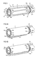
- Figure 2A shows a cap 3 having orientation features 34 and snap features 33, whereby the orientation features 34 ensure that the cap 3 can be attached onto the housing 2 only at one specific orientation.
- the cap 3 comprises a closed end 32 and an open end 31, wherein the closed end 32 is more rigid than the open end 31.
- Some of the orientation features 34 are formed as ribs 34 and are located near the closed end 32 of the cap 3.
- three ribs 34a are arranged at symmetric positions around the longitudinal axis 1.
- the cap 3 comprises orientation features 34 in the form of two protrusions 34b having curved end faces.
- the protrusions 34b are arranged at diametrically opposed positions.
- a snap feature 33 is located at the inner surface of each protrusion 34b.
- the end face 35 of the cap 3 also comprises two flat sections 35a arranged between the curved sections 35b of the protrusions 34b.
- FIG 2B shows a cartridge holder 4 which can be attached to the rear part 21 of the housing 2 of an injection device 1.
- the cartridge holder 4 comprises securing means 46 which engage with mating securing means at the rear part 21 of the housing 2 when the rear part 41 of the cartridge holder 4 is inserted into the rest of the housing 2.
- the cartridge holder 4 At its front part 42, the cartridge holder 4 comprises a thread 48, where a needle unit (not shown here) can be attached.
- the cartridge holder 4 can be covered by the cap 3 as shown in Figure 1 .
- the cartridge holder 4 comprises mating snap features 43 which are engagable with the snap features 33 of the cap 3.
- the cartridge holder 4 comprises mating orientation features 44 which, by interaction with the orientation features 34 of the cap 3, ensure that the cap 3 can be attached onto the housing 2 only at a single orientation.
- the cartridge holder 4 comprises three grooves 44a where the ribs 34a of the cap 3 can engage.
- the grooves 44a have a generous lead in to aid the location of the ribs 34a and to enable the user to twist off the cap 3 in order to remove it.
- the grooves 44a are broader than the ribs 34a, such that the ribs 34a may engage also when an orientation near the correct orientation has been found, and have inclined side faces.
- two diametrically opposed recesses 44b are formed. By the recesses 44b, mating orientation features 44 for the protrusions 34b of the cap 3 are provided.
- the cartridge holder 4 has a flank profile 45 which matches the end face 35 of the cap 3. Accordingly, the flank profile 45 comprises a mating flat section 45a and a mating curved section 45b, whereby the twisting off of the cap 3 is enabled.
- Figure 3 shows an assembly of the cap 3 and the housing 2 in the appropriate orientation.
- the cartridge holder 4 as shown in Figure 2B has been fixed to the rear part 21 of the housing 2 by its securing means 46 and is covered by the cap 3.
- Both the cap 3 and the rear part 21 of the housing 2 comprise a rail 37, 24, whereby a user can easily visually identify the correct orientation of the cap 3 on the housing 2.
- the front part 32 of the cap 3 and the underlying cartridge holder 4 and cartridge 5 is shown in a cross sectional view at the locations marked by the lines A-A in Figures 2A and 2B .
- the ribs 34a of the cap 3 are in the correct orientation to engage with the mating grooves 44a of the cartridge holder 4.
- the protrusions 34b of the cap 3 are in the correct orientation to engage with the recesses 45b of the cartridge holder 4. In this orientation, the cap 3 can be fully assembled onto the housing 2 such that the snap features 33 of the cap 3 can engage with the mating snap features 43 at the cartridge holder 4.
- Figure 4A shows an attempted assembly of a cap 3 and a housing 2 in a first wrong orientation.
- the cap 3 is out of position by 180°, which can easily be seen by the mismatch of the rail 37 on the cap 3 and the rail 47 on the housing 2.
- the ribs 34a of the cap 3 cannot engage with the grooves 44a.
- a further assembly of the cap 3 on the housing 2 is blocked by the abutment of the front end of the ribs 34a and a front face 49 of the cartridge holder 4, although the protrusions 34b would allow an assembly of the cap 3 onto the housing 2.
- the ribs 34a are located such that an assembly is blocked before the snap features 33 on the cap 3 can engage with the mating snap features 43 at the cartridge holder 2.
- Figure 4B shows an attempted assembly of a cap 3 and a housing 2 in a second wrong orientation.
- the cap 3 as shown in Figure 4A has been rotated so that the ribs 34a are close to engage with the grooves 44a.
- the curved end faces of the protrusions 34b abut with the flat sections 45a of the cartridge holder 4, whereby the engagement of the ribs 34a is prevented due to the axial offset caused by the position of the protrusions 34b.
- the cap 3 can be rotated relative to the housing 2 with the protrusions 34b abutting the flank profile 45 until the correct orientation has been found and the cap 3 can be pushed fully home.
- the snap features 33 of the cap 3 engage with the mating snap features 43 of the cartridge holder 4.
- the cap 3 may be removed by applying a twisting, or a combined twisting and pulling action to the cap 3 relative to the housing 2.
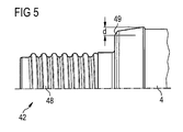
- Figure 5 shows the front part 42 of a cartridge holder 4.
- a limited material thickness d for the grooves 44a is available. Therefore, preferably, at least two or more orientation features 34 on the cap 3 and mating orientation features 44 on the cartridge holder 4 are provided. In this case, also when the cap 3 is assembled off axis, at least one of the orientation features 34 will block the full assembly of the cap until the correct orientation has been found.
Landscapes
- Health & Medical Sciences (AREA)
- Engineering & Computer Science (AREA)
- Hematology (AREA)
- Anesthesiology (AREA)
- Biomedical Technology (AREA)
- Heart & Thoracic Surgery (AREA)
- Vascular Medicine (AREA)
- Life Sciences & Earth Sciences (AREA)
- Animal Behavior & Ethology (AREA)
- General Health & Medical Sciences (AREA)
- Public Health (AREA)
- Veterinary Medicine (AREA)
- Environmental & Geological Engineering (AREA)
- Infusion, Injection, And Reservoir Apparatuses (AREA)
Abstract
A medication delivery device (1) comprises a housing (2) and a cap (3) attachable onto the housing (2). The cap (3) comprises at least one snap feature (4) to attach the cap (3) onto the housing (2) and at least one orientation feature (5) to define the orientation of the cap (3) relative to the housing (2). Here, at least one orientation feature (5) is located at a rigid part of the cap (3) and at least one snap feature (4) is located at a less rigid part of the cap (3).
Description
- This disclosure relates to a medication delivery device comprising a cap which can be attached onto a housing of the device. In particular, it relates to a cap which can be attached onto the housing only in a single orientation relative to the housing.
- The patent application
EP 1923083 A1 discloses an injection device for setting and dispensing a fixed dose of a medicament. Here, a removable cap can be releasably retained over a distal end of a cartridge retaining part. - The patent
EP 1007115 B1 discloses an injection device comprising a cap having a curved edge at its open end. - It is an aim of the present invention to provide a medication delivery device, wherein a cap can be attached onto a housing in a defined orientation and wherein an attachment in a wrong orientation is efficiently prevented.
- According to a first aspect of the present invention, a medication delivery device is provided comprising a housing and a cap attachable onto the housing. The cap comprises at least one snap feature to attach the cap onto the housing and at least one orientation feature to define the orientation of the cap relative to the housing when the cap is attached onto the housing. At least one of the orientation features is located at a rigid part of the cap and at least one of the snap features is located at a less rigid part of the cap.
- The medication delivery device may be a pen-type injection device comprising a cartridge holder, wherein a cartridge comprising a medicament is retained. Preferably, the cap is attachable onto the device such that it covers at least a part of the cartridge holder. This may be useful for protecting the cartridge, in particular when the cartridge is made of a breakable material like glass, or for protecting a needle unit at the distal end of the cartridge holder.
- The cap may comprise a window through which information provided by the cartridge or the cartridge holder is visible for the user. In the case that the information is visible only when the cap is attached in a certain orientation relative to the housing, the appropriate rotational orientation of the cap has to be ensured.
- For this aim, the cap comprises at least one orientation feature. In a preferred embodiment, the housing comprises at least one mating orientation feature which interacts with at least one of the orientation features of the cap. Preferably, for each orientation feature on the cap a mating orientation feature on the housing is provided.
- If all orientation features were located at a flexible part of the cap, i.e., a part where the cap can easily be elastically deformed, the cap might be attachable to the housing also in a wrong orientation. Here, the cap may be forced onto the housing by a deformation at its flexible part where the orientation features are located and thereby, the orientation features bump over the mating orientation features of the housing. However, for an orientation feature which is located at a rigid part of the cap, such an elastic deformation and the resulting "bump over" may be prevented.
- At least one snap feature of the cap is located at a less rigid part of the cap. In a preferred embodiment, the housing comprises at least one mating snap feature which is engageable with at least one of the snap features of the cap. For the engagement of a snap feature with a mating snap feature, a certain elastic deformability of the cap may be required. Preferably, for every snap feature on the cap a mating snap feature on the housing exists.
- Accordingly, the separate positioning of at least one orientation feature at a rigid part of the housing and of at least one snap feature at a less rigid part of the housing allows a reliable attachment of the cap at the right orientation relative to the housing.
- The medication delivery device may have a longitudinal axis. In this case, also the cap may extend along the longitudinal axis, and the rigidity of the cap may vary along the longitudinal axis. Here, the snap feature located at a less rigid part of the cap and the orientation feature located at a rigid part of the cap may have an offset along the longitudinal axis.
- The cap may comprise an open end and a closed end. Preferably, at least one of the snap features is located near the open end of the cap and the orientation feature located at a rigid part of the cap is displaced from the snap feature in a direction towards the closed end of the cap. Preferably, the cap is more rigid at its closed end than at its open end. This means that the cap can be more easily elastically deformed at its closed end than at its rigid end. As an example, the cap may be of a plastic material such as Polypropylen which may be easily deformable at the open end of the cap.
- In one embodiment, the orientation feature comprises a rib. The rib may extend towards a longitudinal axis of the medication delivery device. Preferably, the housing comprises a groove where the rib can engage.
- The cap may comprise several orientation features, wherein the orientation features in combination ensure that the cap is attached in the right orientation onto the housing. Here, some of the orientation features may be located at a rigid part of the cap and others may be located at a less rigid part of the cap.
- In a preferred embodiment, the medication delivery device comprises a plurality of orientation features which have an angular offset around the longitudinal axis.
- Preferably, these orientation features simultaneously interact with mating orientation features of the housing or with parts of the housing which prevent an attachment of the cap. By the simultaneous interaction of many orientation features a maximum counterforce can be achieved when a user tries to attach the cap in a wrong orientation.
- In a preferred embodiment, several orientation features are located at the same axial position and at an angular offset relative to the longitudinal axis.
- In this case, the misplacement of the cap can be prevented efficiently even if a clearance between the inside diameter of the cap and the outside diameter of the housing exists. If only one orientation feature was present at a certain position at the longitudinal axis, there would be a high risk that the cap would be assembled on the housing off axis without the orientation feature preventing the full assembly. However, in the case that several orientation features, e. g. two diametrically opposed orientation features, are provided at a certain position, at least one orientation feature may prevent the assembly unless the correct orientation is found.
- In a preferred embodiment, several orientation features are located at symmetric positions around the longitudinal axes of the device.
- In this case, due to the symmetry, several orientations of the cap relative to the housing may be allowed. In order to allow only one single orientation, some of the orientation features may be located at other positions of the cap. When placing several orientation features at symmetric positions, either all or none of these orientation features interact with mating orientation features. Thereby, a maximum counterforce is exerted when a user tries to assemble the cap in the wrong orientation. In a preferred embodiment, the cap comprises three orientation features which are located at symmetric position around the longitudinal axes.
- In one embodiment, the mating orientation features at the housing comprise a lead in to assist the assembly of the cap and the housing.
- Thereby, the cap may be guided into the right orientation when a user tries to assemble the cap onto the housing in an orientation slightly deviating from the right orientation. The lead in may also allow a twisting off of the cap from the housing.
- In one embodiment, the cap comprises at least one orientation feature which is located at the open end of the cap.
- The sum of the orientation features which are arranged at a rigid part of the cap and the orientation features arranged at the open end of the cap may define a single orientation of the cap on the housing.
- As an example, the end face of the cap comprises at least one protrusion. In a preferred embodiment, the end face of the cap comprises two protrusions which are located at symmetric positions around the longitudinal axes. Here, two possible orientations of the cap are allowed. However, in combination with orientation features at the rigid part of the cap, only a single orientation is possible.
- Preferably, at least one orientation feature at the rigid part of the cap is located such that the cap snap feature does not fully reach a mating snap feature before the right orientation has been found.
- At least one of the snap features of the cap may be located at the protrusion at the open end of the cap.
- The medication delivery device may comprise several snap features. Preferably, the snap features are located at a less rigid part of the cap. Also here, some of the snap features may be located at a more rigid part of the cap.
- Other features will become apparent from the following detailed description when considered in conjunction with the accompanying drawings.
-
Figure 1 shows a pen-type injection device comprising a cap, -
Figure 2A shows a cap having orientation features and snap features, -
Figure 2B shows a cartridge holder having mating snap features and mating orientation features, -
Figure 3 shows an assembly of a cap and a housing in the right orientation, -
Figure 4A shows an attempted assembly of a cap and a housing in a first wrong orientation, -
Figure 4B shows an attempted assembly of a cap and a housing in a second wrong orientation, -
Figure 5 shows the front part of a cartridge holder. -
Figure 1 shows a pen-type injection device 1 having alongitudinal axis 1. Theinjection device 1 comprises ahousing 2 with arear part 21 and acartridge holder 4, wherein acartridge 5 is retained. Acap 3 is attached onto thehousing 2 and covers thecartridge holder 4. Through awindow 36 in thecap 3, thetransparent cartridge holder 4 and thecartridge 5 is visible. A user may set a dose by twisting adose dial element 23 and inject a dose by pushing adose button 22. Thereby, apiston 51 in thecartridge 5 is moved forward and the medicament is pressed out of thecartridge 5. By the position of thepiston 51 inside thecartridge 5 the user is informed on the filling status of thecartridge 5. Ascale 52 at thecartridge holder 5 indicates how many doses are left in theinjection device 1. In other embodiments, the scale may be located at thecartridge 5. In order to ensure that thescale 52 is always visible to a user, thecap 3 has to be attached onto thehousing 2 in the appropriate orientation. -
Figure 2A shows acap 3 having orientation features 34 and snap features 33, whereby the orientation features 34 ensure that thecap 3 can be attached onto thehousing 2 only at one specific orientation. Thecap 3 comprises aclosed end 32 and anopen end 31, wherein theclosed end 32 is more rigid than theopen end 31. Some of the orientation features 34 are formed as ribs 34 and are located near theclosed end 32 of thecap 3. Here, threeribs 34a are arranged at symmetric positions around thelongitudinal axis 1. At itsopen end 31, thecap 3 comprises orientation features 34 in the form of twoprotrusions 34b having curved end faces. Theprotrusions 34b are arranged at diametrically opposed positions. At the inner surface of eachprotrusion 34b, asnap feature 33 is located. The end face 35 of thecap 3 also comprises twoflat sections 35a arranged between thecurved sections 35b of theprotrusions 34b. -
Figure 2B shows acartridge holder 4 which can be attached to therear part 21 of thehousing 2 of aninjection device 1. For this aim, thecartridge holder 4 comprises securing means 46 which engage with mating securing means at therear part 21 of thehousing 2 when therear part 41 of thecartridge holder 4 is inserted into the rest of thehousing 2. At itsfront part 42, thecartridge holder 4 comprises athread 48, where a needle unit (not shown here) can be attached. Thecartridge holder 4 can be covered by thecap 3 as shown inFigure 1 . For a releasable attachment of thecap 3, thecartridge holder 4 comprises mating snap features 43 which are engagable with the snap features 33 of thecap 3. Moreover, thecartridge holder 4 comprises mating orientation features 44 which, by interaction with the orientation features 34 of thecap 3, ensure that thecap 3 can be attached onto thehousing 2 only at a single orientation. - At a
front face 49 near thethread 48, thecartridge holder 4 comprises threegrooves 44a where theribs 34a of thecap 3 can engage. Thegrooves 44a have a generous lead in to aid the location of theribs 34a and to enable the user to twist off thecap 3 in order to remove it. In particular, thegrooves 44a are broader than theribs 34a, such that theribs 34a may engage also when an orientation near the correct orientation has been found, and have inclined side faces. Towards therear part 41 of thecartridge holder 4, two diametricallyopposed recesses 44b are formed. By therecesses 44b, mating orientation features 44 for theprotrusions 34b of thecap 3 are provided. At therecesses 44b, thecartridge holder 4 has aflank profile 45 which matches theend face 35 of thecap 3. Accordingly, theflank profile 45 comprises a matingflat section 45a and a matingcurved section 45b, whereby the twisting off of thecap 3 is enabled. -
Figure 3 shows an assembly of thecap 3 and thehousing 2 in the appropriate orientation. Here, thecartridge holder 4 as shown inFigure 2B has been fixed to therear part 21 of thehousing 2 by its securing means 46 and is covered by thecap 3. Both thecap 3 and therear part 21 of thehousing 2 comprise arail cap 3 on thehousing 2. Thefront part 32 of thecap 3 and theunderlying cartridge holder 4 andcartridge 5 is shown in a cross sectional view at the locations marked by the lines A-A inFigures 2A and 2B . - In
Figure 3 , theribs 34a of thecap 3 are in the correct orientation to engage with themating grooves 44a of thecartridge holder 4. Also theprotrusions 34b of thecap 3 are in the correct orientation to engage with therecesses 45b of thecartridge holder 4. In this orientation, thecap 3 can be fully assembled onto thehousing 2 such that the snap features 33 of thecap 3 can engage with the mating snap features 43 at thecartridge holder 4. -
Figure 4A shows an attempted assembly of acap 3 and ahousing 2 in a first wrong orientation. Here, thecap 3 is out of position by 180°, which can easily be seen by the mismatch of therail 37 on thecap 3 and therail 47 on thehousing 2. At this orientation, theribs 34a of thecap 3 cannot engage with thegrooves 44a. A further assembly of thecap 3 on thehousing 2 is blocked by the abutment of the front end of theribs 34a and afront face 49 of thecartridge holder 4, although theprotrusions 34b would allow an assembly of thecap 3 onto thehousing 2. Theribs 34a are located such that an assembly is blocked before the snap features 33 on thecap 3 can engage with the mating snap features 43 at thecartridge holder 2. -
Figure 4B shows an attempted assembly of acap 3 and ahousing 2 in a second wrong orientation. Here, thecap 3 as shown inFigure 4A has been rotated so that theribs 34a are close to engage with thegrooves 44a. However, at this orientation, the curved end faces of theprotrusions 34b abut with theflat sections 45a of thecartridge holder 4, whereby the engagement of theribs 34a is prevented due to the axial offset caused by the position of theprotrusions 34b. Thecap 3 can be rotated relative to thehousing 2 with theprotrusions 34b abutting theflank profile 45 until the correct orientation has been found and thecap 3 can be pushed fully home. In that case, the snap features 33 of thecap 3 engage with the mating snap features 43 of thecartridge holder 4. Thecap 3 may be removed by applying a twisting, or a combined twisting and pulling action to thecap 3 relative to thehousing 2. -
Figure 5 shows thefront part 42 of acartridge holder 4. Here, at thefront face 49 only a limited material thickness d for thegrooves 44a is available. Therefore, preferably, at least two or more orientation features 34 on thecap 3 and mating orientation features 44 on thecartridge holder 4 are provided. In this case, also when thecap 3 is assembled off axis, at least one of the orientation features 34 will block the full assembly of the cap until the correct orientation has been found. - Other implementations are within the scope of the following claims. Elements of different implementations may be combined to form implementations not specifically described herein.
-
- 1 injection device
- 2 housing
- 21 rear part of housing
- 22 dose button
- 23 dose dial element
- 24 rail on housing
- 3 cap
- 31 open end of cap
- 32 closed end of cap
- 33 snap feature
- 34 orientation feature
- 34a rib
- 34b protrusion
- 35 end face
- 35a flat section
- 35b curved section
- 36 window
- 37 rail on cap
- 4 cartridge holder
- 41 rear part of cartridge holder
- 42 front part of cartridge holder
- 43 mating snap feature
- 44 mating orientation feature
- 44a groove
- 44b recess
- 45 flank profile
- 45a mating flat section
- 45b mating curved section
- 46 securing means
- 47 rail on cartridge holder
- 48 thread
- 49 front face
- 5 cartridge
- 51 piston
- 52 scale
l longitudinal axis
Claims (19)
- A medication delivery device comprising:a housing (2),a cap (3) attachable onto the housing (2),wherein the cap (3) comprises at least one snap feature (33) to attach the cap (3) onto the housing (2) and at least one orientation feature (34) to define the orientation of the cap (3) relative to the housing (2) when attached to the housing (2),
wherein at least one of the orientation features (34) is located at a rigid part of the cap (3) and at least one of the snap features (33) is located at a less rigid part of the cap (3). - The medication delivery device according to claim 1,
wherein the orientation features (34) allow a full assembly of the cap (3) and the housing (2) only in a single orientation of the cap (3) relative to the housing (2). - The medication delivery device according to any of claims 1 or 2 having a longitudinal axis (1),
wherein the snap feature (33) located at a less rigid part of the cap (3) and the orientation feature (34) located at a rigid part of the cap (3) have an offset along the longitudinal axis (1). - The medication delivery device according to any of claims 1 to 3,
wherein the cap (3) comprises an open end (31) and a closed end (32) and
wherein at least one of the snap features (33) is located near the open end (31) of the cap (3) and the orientation feature (34) located at a rigid part of the cap (3) is displaced from the snap feature (33) in a direction towards the closed end (32) of the cap (3). - The medication delivery device according to any of claims 1 to 4,
wherein the orientation features (34) comprise a rib (34a). - The medication delivery device according to any of claims 3 to 5,
comprising a plurality of orientation features (34) having an angular offset around the longitudinal axis (1). - The medication delivery device according to claim 6,
wherein three orientation features (34) are located at symmetric positions around the longitudinal axis (1). - The medication delivery device according to any of claims 1 to 7,
wherein the housing (2) comprises at least one mating snap feature (43) engageable with at least one of the snap features (33) and at least one mating orientation feature (44) interacting with at least one of the orientation features (34). - The medication delivery device according to claim 8,
wherein the mating orientation feature (43) comprises a lead in to assist the assembly of the cap (3) and the housing (2). - The medication delivery device according to claim 9,
wherein the mating orientation feature (43) comprises a groove (44a). - The medication delivery device according to any of claims 4 to 10,
wherein the cap (3) comprises at least one orientation feature (34) which is located at the open end (31) of the cap (3). - The medication delivery device according to claim 11,
wherein the cap (3) comprises at least one protrusion (34b) at its open end (31). - The medication delivery device according to claim 12,
wherein the cap (3) comprises two protrusions (34b) at its open end (31) which are located at symmetric positions around the longitudinal axis (1). - The medication delivery device according to any of claims 12 or 13,
wherein at least one of the snap features (33) of the cap (3) is located at the protrusion (34b). - The medication delivery device according to any of claims 1 to 14,
wherein the housing (2) comprises a cartridge holder (4) enclosing a cartridge (5) containing a medicament and wherein the cap (3) can be attached such that it covers at least a part of the cartridge holder (4). - The medication delivery device according to any of claims 1 to 15,
wherein the cap (3) comprises a window (36). - The medication delivery device according to claim 16,
wherein one of or both the cartridge (5) and the cartridge holder (4) have an indication which is visible through the window (36) when the cap (3) is attached on the housing (2). - The medication delivery device according to claim 17,
wherein the indication comprises a scale (52). - The medication delivery device according to any of claims 1 to 18,
wherein the medication delivery device is a pen-type injection device (1).
Priority Applications (7)
| Application Number | Priority Date | Filing Date | Title |
|---|---|---|---|
| EP08022318A EP2201974A1 (en) | 2008-12-23 | 2008-12-23 | Medication delivery device |
| DK09798918.0T DK2381986T3 (en) | 2008-12-23 | 2009-12-18 | PHARMACEUTICAL MANAGEMENT DEVICE |
| PCT/EP2009/067477 WO2010072661A1 (en) | 2008-12-23 | 2009-12-18 | Drug delivery device |
| JP2011542783A JP5734202B2 (en) | 2008-12-23 | 2009-12-18 | Drug delivery device |
| EP09798918.0A EP2381986B1 (en) | 2008-12-23 | 2009-12-18 | Drug delivery device |
| US13/139,919 US8568364B2 (en) | 2008-12-23 | 2009-12-18 | Drug delivery device |
| CA2746978A CA2746978A1 (en) | 2008-12-23 | 2009-12-18 | Drug delivery device |
Applications Claiming Priority (1)
| Application Number | Priority Date | Filing Date | Title |
|---|---|---|---|
| EP08022318A EP2201974A1 (en) | 2008-12-23 | 2008-12-23 | Medication delivery device |
Publications (1)
| Publication Number | Publication Date |
|---|---|
| EP2201974A1 true EP2201974A1 (en) | 2010-06-30 |
Family
ID=40491095
Family Applications (2)
| Application Number | Title | Priority Date | Filing Date |
|---|---|---|---|
| EP08022318A Ceased EP2201974A1 (en) | 2008-12-23 | 2008-12-23 | Medication delivery device |
| EP09798918.0A Active EP2381986B1 (en) | 2008-12-23 | 2009-12-18 | Drug delivery device |
Family Applications After (1)
| Application Number | Title | Priority Date | Filing Date |
|---|---|---|---|
| EP09798918.0A Active EP2381986B1 (en) | 2008-12-23 | 2009-12-18 | Drug delivery device |
Country Status (6)
| Country | Link |
|---|---|
| US (1) | US8568364B2 (en) |
| EP (2) | EP2201974A1 (en) |
| JP (1) | JP5734202B2 (en) |
| CA (1) | CA2746978A1 (en) |
| DK (1) | DK2381986T3 (en) |
| WO (1) | WO2010072661A1 (en) |
Cited By (2)
| Publication number | Priority date | Publication date | Assignee | Title |
|---|---|---|---|---|
| WO2012065965A1 (en) * | 2010-11-19 | 2012-05-24 | Sanofi-Aventis Deutschland Gmbh | Cap for a drug delivery device and method for manufacturing a cap for a drug delivery device |
| WO2013149979A1 (en) * | 2012-04-05 | 2013-10-10 | Sanofi-Aventis Deutschland Gmbh | Pen-type injector |
Families Citing this family (23)
| Publication number | Priority date | Publication date | Assignee | Title |
|---|---|---|---|---|
| EP2292286A1 (en) * | 2009-09-07 | 2011-03-09 | Sanofi-Aventis Deutschland GmbH | Drive mechanism for a medication delivery device and medication delivery device |
| DK2475411T3 (en) * | 2009-09-07 | 2015-04-07 | Sanofi Aventis Deutschland | A drive mechanism for device for drug delivery |
| BR112012007310A2 (en) * | 2009-09-30 | 2016-04-19 | Sanofi Aventis Deutschland | drive mechanism for a drug delivery device and use of a reset member for a drive mechanism |
| DK2482889T3 (en) * | 2009-09-30 | 2016-05-17 | Sanofi Aventis Deutschland | ACCOMMODATION drug delivery device |
| TW201127435A (en) * | 2009-09-30 | 2011-08-16 | Sanofi Aventis Deutschland | Drive mechanism for a drug delivery device |
| WO2011039205A2 (en) * | 2009-09-30 | 2011-04-07 | Sanofi-Aventis Deutschland Gmbh | Drug delivery device and drive member for a drug delivery device |
| JP5813097B2 (en) * | 2010-04-23 | 2015-11-17 | サノフィ−アベンティス・ドイチュラント・ゲゼルシャフト・ミット・ベシュレンクテル・ハフツング | Coded cartridge holder system for fluid delivery devices |
| BR112013032089A2 (en) * | 2011-06-17 | 2016-12-13 | Sanofi Aventis Deutschland | drug delivery device for administering a predefined dose of a drug |
| GB2494453B (en) * | 2011-09-12 | 2013-08-07 | Owen Mumford Ltd | Injector assembly |
| US11413399B2 (en) * | 2015-11-27 | 2022-08-16 | Sanofi-Aventis Deutschland Gmbh | Injection device with mounting aid for a supplementary device |
| USD819198S1 (en) | 2016-04-28 | 2018-05-29 | Amgen Inc. | Autoinjector with removable cap |
| WO2019033092A1 (en) * | 2017-08-11 | 2019-02-14 | West Pharmaceutical Services, Inc. | Integrated passive syringe needle safety system with torqued compression spring and multi-part collar |
| USD1010811S1 (en) | 2019-09-30 | 2024-01-09 | Amgen Inc. | Handheld drug delivery device |
| USD1030040S1 (en) | 2020-01-14 | 2024-06-04 | Amgen Inc. | Handheld drug delivery device |
| USD1030041S1 (en) | 2020-01-14 | 2024-06-04 | Amgen Inc. | Handheld drug delivery device |
| USD974547S1 (en) | 2020-11-05 | 2023-01-03 | Amgen Inc. | Handheld drug delivery device |
| USD973866S1 (en) | 2020-11-05 | 2022-12-27 | Amgen Inc. | Handheld drug delivery device |
| JP2021500643S (en) | 2020-11-05 | 2022-12-27 | Syringe | |
| USD985116S1 (en) | 2021-03-10 | 2023-05-02 | Amgen Inc. | Handheld drug delivery device |
| USD985117S1 (en) | 2021-03-10 | 2023-05-02 | Amgen Inc. | Handheld drug delivery device |
| USD985118S1 (en) | 2021-03-10 | 2023-05-02 | Amgen Inc. | Handheld drug delivery device |
| USD985119S1 (en) | 2021-03-30 | 2023-05-02 | Amgen Inc. | Handheld drug delivery device |
| CN120129549A (en) * | 2022-10-31 | 2025-06-10 | 赛诺菲 | Drug delivery device with two-part user indicator |
Citations (7)
| Publication number | Priority date | Publication date | Assignee | Title |
|---|---|---|---|---|
| EP0327910A2 (en) * | 1988-02-10 | 1989-08-16 | D.C.P. Af 1988 A/S | A dosage unit for dosing a number of measured quantities of a liquid, such as an insulin preparation, from a cartridge |
| US5259840A (en) * | 1991-09-03 | 1993-11-09 | Boris Craig R | Locking syringe |
| US5735827A (en) * | 1996-09-26 | 1998-04-07 | Becton, Dickinson And Company | Needle assembly having locking enclosure |
| US6210369B1 (en) * | 1997-12-16 | 2001-04-03 | Meridian Medical Technologies Inc. | Automatic injector |
| US20060206057A1 (en) * | 2003-08-12 | 2006-09-14 | Eli Lily And Company Patent Division | Medication dispensing apparatus with triple screw threads for mechanical advantage |
| EP1007115B1 (en) | 1997-06-04 | 2006-11-02 | Eli Lilly And Company | Medication delivery apparatus |
| EP1923083A1 (en) | 2006-11-17 | 2008-05-21 | Sanofi-Aventis Deutschland GmbH | Drive mechanisms for use in drug delivery devices |
Family Cites Families (6)
| Publication number | Priority date | Publication date | Assignee | Title |
|---|---|---|---|---|
| US5645534A (en) * | 1994-06-24 | 1997-07-08 | Becton Dickinson And Company | Time of last injection indicator for medication delivery pen |
| ES2133090B1 (en) * | 1997-02-21 | 2000-04-01 | Uriach & Cia Sa J | NEW APPLICATOR FOR THE ADMINISTRATION OF SEMI-SOLID MEDICATIONS. |
| JP4688853B2 (en) * | 2001-12-13 | 2011-05-25 | パナソニック株式会社 | Medical dosing device |
| US6936034B2 (en) * | 2003-11-26 | 2005-08-30 | Tasheem Watkins | Insulin syringe with magnified sheath |
| JP4507671B2 (en) * | 2004-03-31 | 2010-07-21 | パナソニック株式会社 | Medical dosing device |
| US7780637B2 (en) * | 2006-11-06 | 2010-08-24 | Steven Jerde | Medical device container |
-
2008
- 2008-12-23 EP EP08022318A patent/EP2201974A1/en not_active Ceased
-
2009
- 2009-12-18 JP JP2011542783A patent/JP5734202B2/en not_active Expired - Fee Related
- 2009-12-18 EP EP09798918.0A patent/EP2381986B1/en active Active
- 2009-12-18 DK DK09798918.0T patent/DK2381986T3/en active
- 2009-12-18 CA CA2746978A patent/CA2746978A1/en not_active Abandoned
- 2009-12-18 WO PCT/EP2009/067477 patent/WO2010072661A1/en not_active Ceased
- 2009-12-18 US US13/139,919 patent/US8568364B2/en active Active
Patent Citations (7)
| Publication number | Priority date | Publication date | Assignee | Title |
|---|---|---|---|---|
| EP0327910A2 (en) * | 1988-02-10 | 1989-08-16 | D.C.P. Af 1988 A/S | A dosage unit for dosing a number of measured quantities of a liquid, such as an insulin preparation, from a cartridge |
| US5259840A (en) * | 1991-09-03 | 1993-11-09 | Boris Craig R | Locking syringe |
| US5735827A (en) * | 1996-09-26 | 1998-04-07 | Becton, Dickinson And Company | Needle assembly having locking enclosure |
| EP1007115B1 (en) | 1997-06-04 | 2006-11-02 | Eli Lilly And Company | Medication delivery apparatus |
| US6210369B1 (en) * | 1997-12-16 | 2001-04-03 | Meridian Medical Technologies Inc. | Automatic injector |
| US20060206057A1 (en) * | 2003-08-12 | 2006-09-14 | Eli Lily And Company Patent Division | Medication dispensing apparatus with triple screw threads for mechanical advantage |
| EP1923083A1 (en) | 2006-11-17 | 2008-05-21 | Sanofi-Aventis Deutschland GmbH | Drive mechanisms for use in drug delivery devices |
Cited By (6)
| Publication number | Priority date | Publication date | Assignee | Title |
|---|---|---|---|---|
| WO2012065965A1 (en) * | 2010-11-19 | 2012-05-24 | Sanofi-Aventis Deutschland Gmbh | Cap for a drug delivery device and method for manufacturing a cap for a drug delivery device |
| WO2013149979A1 (en) * | 2012-04-05 | 2013-10-10 | Sanofi-Aventis Deutschland Gmbh | Pen-type injector |
| CN104519928A (en) * | 2012-04-05 | 2015-04-15 | 赛诺菲-安万特德国有限公司 | Pen-type injector |
| CN104519928B (en) * | 2012-04-05 | 2017-09-22 | 赛诺菲-安万特德国有限公司 | pen-type injector |
| AU2013245105B2 (en) * | 2012-04-05 | 2017-10-19 | Sanofi-Aventis Deutschland Gmbh | Pen-type injector |
| US9849245B2 (en) | 2012-04-05 | 2017-12-26 | Sanofi-Aventis Deutschland Gmbh | Pen-type injector |
Also Published As
| Publication number | Publication date |
|---|---|
| DK2381986T3 (en) | 2020-02-24 |
| EP2381986A1 (en) | 2011-11-02 |
| JP2012513265A (en) | 2012-06-14 |
| US8568364B2 (en) | 2013-10-29 |
| US20120022462A1 (en) | 2012-01-26 |
| CA2746978A1 (en) | 2010-07-01 |
| JP5734202B2 (en) | 2015-06-17 |
| WO2010072661A1 (en) | 2010-07-01 |
| EP2381986B1 (en) | 2019-11-27 |
Similar Documents
| Publication | Publication Date | Title |
|---|---|---|
| EP2381986B1 (en) | Drug delivery device | |
| US11806510B2 (en) | Shell for a medicament delivery device | |
| EP1755706B1 (en) | Injection device | |
| JP5677288B2 (en) | Drug delivery device having an enlarged cartridge at the distal end | |
| US9539848B2 (en) | Writing instrument having a movable protective sleeve | |
| US9125994B2 (en) | Drug delivery device with dose dial sleeve rotational stop | |
| EP2919834B1 (en) | Injection needle assembly | |
| EP3708202A1 (en) | An injector needle cap and/or liner remover | |
| JP2013542808A (en) | Container holder assembly | |
| US10493214B2 (en) | Medical injection device | |
| US20240325646A1 (en) | Injector needle cap and/or liner remover | |
| US20190125978A1 (en) | Safety needles and methods of use thereof | |
| JP2008237454A (en) | Protector | |
| EP3616736A1 (en) | Method and devices for receiving a cannula | |
| US20150032062A1 (en) | Medical Injection Device | |
| JP2021100588A (en) | Housing for mounting container on injection pen, assembly for forming injection agent storage tank for injection pen and injection pen including assembly | |
| JP7680466B2 (en) | Medical container, an adapter for mounting to the medical container, and a drug delivery device including the medical container | |
| JP5793416B2 (en) | Pump container and cosmetics | |
| WO2012000570A1 (en) | Medical delivery device with battery compartment having elements facilitating battery insertion and removal | |
| JP4383867B2 (en) | Improved injection device | |
| HK1141745B (en) | Injection device for dispensing a medicament |
Legal Events
| Date | Code | Title | Description |
|---|---|---|---|
| PUAI | Public reference made under article 153(3) epc to a published international application that has entered the european phase |
Free format text: ORIGINAL CODE: 0009012 |
|
| AK | Designated contracting states |
Kind code of ref document: A1 Designated state(s): AT BE BG CH CY CZ DE DK EE ES FI FR GB GR HR HU IE IS IT LI LT LU LV MC MT NL NO PL PT RO SE SI SK TR |
|
| AX | Request for extension of the european patent |
Extension state: AL BA MK RS |
|
| STAA | Information on the status of an ep patent application or granted ep patent |
Free format text: STATUS: THE APPLICATION HAS BEEN REFUSED |
|
| 18R | Application refused |
Effective date: 20100902 |