EP2201878A2 - Vacuum cleaner with a centrifugal separator - Google Patents
Vacuum cleaner with a centrifugal separator Download PDFInfo
- Publication number
- EP2201878A2 EP2201878A2 EP09178063A EP09178063A EP2201878A2 EP 2201878 A2 EP2201878 A2 EP 2201878A2 EP 09178063 A EP09178063 A EP 09178063A EP 09178063 A EP09178063 A EP 09178063A EP 2201878 A2 EP2201878 A2 EP 2201878A2
- Authority
- EP
- European Patent Office
- Prior art keywords
- centrifugal separator
- air
- vacuum cleaner
- guiding means
- axis
- Prior art date
- Legal status (The legal status is an assumption and is not a legal conclusion. Google has not performed a legal analysis and makes no representation as to the accuracy of the status listed.)
- Granted
Links
Images

Classifications
-
- A—HUMAN NECESSITIES
- A47—FURNITURE; DOMESTIC ARTICLES OR APPLIANCES; COFFEE MILLS; SPICE MILLS; SUCTION CLEANERS IN GENERAL
- A47L—DOMESTIC WASHING OR CLEANING; SUCTION CLEANERS IN GENERAL
- A47L9/00—Details or accessories of suction cleaners, e.g. mechanical means for controlling the suction or for effecting pulsating action; Storing devices specially adapted to suction cleaners or parts thereof; Carrying-vehicles specially adapted for suction cleaners
- A47L9/10—Filters; Dust separators; Dust removal; Automatic exchange of filters
- A47L9/16—Arrangement or disposition of cyclones or other devices with centrifugal action
- A47L9/1608—Cyclonic chamber constructions
-
- A—HUMAN NECESSITIES
- A47—FURNITURE; DOMESTIC ARTICLES OR APPLIANCES; COFFEE MILLS; SPICE MILLS; SUCTION CLEANERS IN GENERAL
- A47L—DOMESTIC WASHING OR CLEANING; SUCTION CLEANERS IN GENERAL
- A47L9/00—Details or accessories of suction cleaners, e.g. mechanical means for controlling the suction or for effecting pulsating action; Storing devices specially adapted to suction cleaners or parts thereof; Carrying-vehicles specially adapted for suction cleaners
- A47L9/0081—Means for exhaust-air diffusion; Means for sound or vibration damping
-
- B—PERFORMING OPERATIONS; TRANSPORTING
- B04—CENTRIFUGAL APPARATUS OR MACHINES FOR CARRYING-OUT PHYSICAL OR CHEMICAL PROCESSES
- B04C—APPARATUS USING FREE VORTEX FLOW, e.g. CYCLONES
- B04C5/00—Apparatus in which the axial direction of the vortex is reversed
- B04C5/08—Vortex chamber constructions
- B04C5/103—Bodies or members, e.g. bulkheads, guides, in the vortex chamber
Definitions
- the present invention relates to a vacuum cleaner having a centrifugal separator having an air inlet passage connected to a suction air guide for dust-laden suction air, a separation space and an air outlet communicating with the separation space via a dip tube and discharging the purified air to the environment. wherein the air inlet duct opens into the centrifugal separator.
- Such vacuum cleaners are known from the prior art.
- Components of such a vacuum cleaner are essentially one or more nozzles for receiving the dust, a suction pipe, which is designed depending on the structure of the vacuum cleaner as a floor, hand or upright vacuum cleaner shorter or longer or rigid or telescopic, a connector which connecting the suction tube with a flexible suction hose, one or more dust container, which may be part of or the centrifugal or is designed as a separate dust collector, a vacuum chamber through which the air is sucked by a motor-blower unit, and given if a fine dust filter for final cleaning of the escaping air.
- the invention has for its object to provide a vacuum cleaner with an improved centrifugal separator, which avoids turbulence in the inlet region, as well as an increased volume flow provides while reducing the noise.
- the vacuum cleaner according to the invention with a centrifugal separator is achieved by a centrifugal separator comprising an air guide means, wherein the air guide means is an area which is generated by continuous screwing of a space curve about the axis of the centrifugal separator.
- Both cyclone and cyclone separators are to be regarded as centrifugal separators, centrifugal forces acting on the particles in the centrifugal force separator and accelerating them radially outward.
- the rotationally displaced air separates the dust into the dust collecting area of the separation space by means of centrifugal forces, or the dust is ejected through a dust outlet into a separate dust collecting tank arranged separately from the separation space.
- Centrifugal separators can be both an integral part of the vacuum cleaner, or be used as a separate unit in a plenum. At least the dust collector can be removed from the vacuum cleaner. Such centrifugal separators are used in particular in so-called bagless vacuum cleaners. As air guidance means those devices are to be considered, which divert the incoming air from its original flow direction in another flow direction.
- the air inlet is advantageously tangential to an air flow in the centrifugal separator and the air guide means deflect the incoming air into a perpendicular to the air inlet protruding helical line.
- the air is thereby converted with largely avoiding turbulence at the entry point and with the lowest possible resistance in a preferably spiral-shaped rotational movement. This ensures that the incoming air and the rotating air are located at the entry point in spaced-apart planes and flow largely unaffected by each other, or almost without mutual collision.
- the air guide means extends by a maximum of one revolution about the axis of the centrifugal separator.
- the air guiding means can guide the air for a maximum of one revolution about the radial axis and thereby unfold the air flow with the dust particles without a limiting channel formation.
- a limiting channel may be disadvantageous in that as large, heavy particles only half a revolution, small, light particles, however, require around three revolutions to reach the ejection into the dust collector.
- the air guide means has a steady, progressive or degressive slope in the direction of the screw.
- the helix has a constant pitch, with a progressive pitch, the pitch of the helix increases, with a degressive pitch, the pitch of the helix decreases.
- a steady pitch of the helix accelerates the dust particles evenly, with contact of the particles with the air-guiding means is largely avoided.
- a progressive slope in particular, ejects the particles into the separation space at the end of the slope and advantageously avoids a collision with the inflowing particles.
- a degressive pitch can be used advantageously in small centrifugal separators to achieve small heights.
- the space curve is a straight line, a convex or a concave curve.
- a convex curve is an outwardly, ie curved into the separation chamber, under a concave curve is to be understood inwardly, ie curved away from the discharge side shape.
- the term curve includes symmetric as well as subsections of symmetric and asymmetric geometries.
- a straight line can be converted into a tool shape with simple means. Curves may have the advantage that at the radial transitions from the air guide means to the inner boundary walls of the centrifugal separator radii are present, which advantageously avoid areas with turbulence and dust deposits.
- the space curve is inclined at an angle between 45 and 135 degrees to the axis of the screwing and, in a particular embodiment, is oriented perpendicular to the axis of the screwing.
- the angle is between the axis of the centrifugal separator, which extends from the air inlet to the dust discharge, and the space curve.
- the surface of the air guiding means points towards the air inlet, at an angle of 135 degrees it shows the surface of the air guiding means in the direction of the dust ejection.
- the surface is perpendicular to the centrifugal separator.
- An inclined into the center of the centrifugal separator air guide surface that is at an angle greater than 90 degrees, can advantageously support the centrifugal force acting on the particle to the effect that during the radial movement to the outside an additional axial movement component is generated in the direction of the dust ejection out.
- a space axis projecting perpendicularly from the axis of the centrifugal separator can advantageously combine the properties of a tilted or rising air guiding means and achieves the best measuring results for an average dust.
- the air guide means has an axial extent with a length between about two thirds of the maximum height of the air inlet channel and the maximum height of the air inlet channel.
- An axial extension is directed in the direction of the axis of the centrifugal separator.
- the term height is the extent defined in the axial direction.
- the air guide means formed integrally with the centrifugal separator or constitutes a separate component of the centrifugal separator.
- a one-piece design of the air guide means together with the inner wall of the centrifugal separator allow a simple tool design and easy assembly assembly.
- With a separate component design of the air guiding means advantageously more complex geometries can be displayed.
- Wear-resistant or differently colored materials are used.
- the air guide means is arranged on a removable or movable housing part of the centrifugal separator.
- the air guide means on a removable or movable housing part of Centrifugal separator be arranged.
- the air guidance means preferably extends in the radial direction away from the axis of the centrifugal separator to the inner wall of the centrifugal separator.
- the particles over the full available width, ie in the radial direction are detected by the air guide means, accelerated to the outside and experienced a spiral or screw movement.
- the air guide means extends in the radial direction away from the axis of the centrifugal separator and has a distance to the inner wall.
- Small light particles take more turns to reach the ejection window than large, heavy particles.
- the air-guiding means are advantageously at a distance from the inner wall, the accelerations caused by the screwing movement of the air, in particular, can act on their own radial centrifugal forces, as well as on their axial forces. This effect results from the short residence time of the particles in the area of the air duct.
- Particularly small particles can thereby experience a safe acceleration.
- no particles can settle between the air guide means and the inner wall of the centrifugal separator as a result of the full-surface air flow on the inner wall, so that a hygienic impression persists especially in transparent versions after prolonged operation.
- the pitch of the air guiding means begins in the air intake passage.
- particularly flat slopes can be achieved, which produce a particularly advantageous low air resistance.
- the air guiding means preferably starts at a boundary surface of the centrifugal separator lying opposite an ejection.
- the inflowing air flow can be immediately offset in a spiral or screw movement.
- the air guide means ends at the end of a slope with a flat plateau.
- air flowing in from the air inlet channel can thereby be prevented from the rotating spiral or screw movement.
- the air guide means is arranged in an advantageous manner with respect to an oblique ejection surface.
- turbulences in the region of the air outlet can thereby be avoided.
- an oblique ejection surface is meant a plane which is not oriented orthogonally to the axis of the centrifugal separator.
- At least the air inlet channel preferably opens tangentially into the separation chamber.
- the air inlet is tangential to an air flow in the centrifugal separator and the air guide means deflect the incoming air into a helix perpendicular to the air inlet. The air is thereby converted with largely avoiding turbulence at the entry point and with the lowest possible resistance in a preferably helical or spiral rotational movement.
- the present invention facilitates with simple and constructive means the realization of a centrifugal separator in which especially a noise reduction and an increased volume flow can be achieved. Furthermore, a higher overall efficiency and an increase in efficiency is achieved.
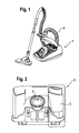
- FIG. 1 an inventive vacuum cleaner 1 is shown, is sucked in the dust-laden air via a floor nozzle and a Saugluft Unit 4, consisting of a length-adjustable suction pipe, a connector to a flexible suction hose into the interior of a housing of the vacuum cleaner 1.
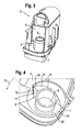
- a centrifugal separator 2 in the FIGS. 2 to 6 is shown in detail.
- the centrifugal separator 2 has a tubular air inlet duct 3, which adjoins the suction air duct 4 of the vacuum cleaner 1 in such a way that the air from the suction air duct 4 flows through it tangentially into the centrifugal separator 2. From there, the air passes into a substantially cylindrical separation chamber 5, in which, similar to a centrifuge according to the principle of centrifugal force, the dust from the air is deposited.
- An air outlet 6 of the centrifugal separator 2 is connected via a dip tube 7 with the separation chamber 5.
- an air guide means 8 in the form of a surface 9 is provided starting from the lower boundary surface 23 of the separation chamber 5, which results from continuous screwing 10 of a radius 14 of a longitudinal axis 11 of the separation chamber 4 about this longitudinal axis 11.
- the air guiding means 8 is formed in one piece with a designed as a pivotable lid housing part 19 of the centrifugal separator 2.
- the lid can be opened to clean the separation chamber 4.
- the lid also covers a collecting chamber, not shown, of the centrifugal separator 2, which can be emptied when the lid is opened.
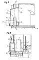
- the threaded surface 9 of the air guide means begins from the mouth of the air inlet duct 3 in the direction of the screw 10 after about 2/3 of a full turn 12 about the longitudinal axis 11 of the centrifugal separator 2.
- the threaded surface 9 of the air duct 8 ends 24 after about 1 / 3 of a full turn 12 at the screw 10 facing edge of the mouth of the air inlet channel 3 and there has an axial extent 17 which corresponds approximately to the height of the mouth of the inlet channel 3. This can ensure that the deflected air does not collide with newly air flowing through the air inlet duct 3 and thereby undesirable turbulence. From the straight edge formed by the end 24 of the surface 9 of the air guiding means 8 extends radially, i.
- the surface 9 of the air guiding means 8 has a linear slope.
- the surface 9 extends in the radial direction of the separation chamber 5 from the central dip tube 7 up to the wall 20 of the cylindrical separation chamber 5.
- the centrifugal separator 2 operates as follows: Air flowing in through the air inlet duct 3 is directed onto the helical path by the air guiding means 8 and flows on this path in the direction of an obliquely arranged ejection surface 16 and an ejection 22 of the separating chamber 5 of the centrifugal separator 2 Centrifugal forces collects while the dust on the wall 20 of the separation chamber and moves there on a spiral path in the direction of ejection 22, through which he leaves the separation chamber 4 and enters the collection chamber. The air, however, undergoes a deflection at the level of the ejection 22 of the separation chamber 4 and leaves the separation chamber 4 through the dip tube 7 and the outlet 6 in the direction of the blower of the vacuum cleaner. 1
- the air guiding means 8 not only improves the dust separation but also reduces the noise generated by the centrifugal separator 2. This may be the comparison of FIGS. 7 and 8 are taken, in each of which the sound power of a centrifugal separator 2 is indicated as a function of frequency. It shows FIG. 7 the sound power of a centrifugal separator 2 without air guide means 8 and FIG. 8 However, it shows that a significant improvement can be achieved, especially in the case of the particularly unpleasant middle frequencies.
- the present invention facilitates with simple and constructive means the realization of a centrifugal separator 2 in which particularly a noise reduction and an increased volume flow are achieved. Furthermore, a higher overall efficiency and an increase in efficiency is achieved.
Abstract
Description
Die vorliegende Erfindung betrifft einen Staubsauger mit einem Fliehkraftabscheider, der einen Lufteinlasskanal aufweist, der mit einer Saugluftführung für staubbeladene Saugluft verbunden ist, einen Abscheideraum und einen Luftauslass, der über ein Tauchrohr mit dem Abscheideraum in Verbindung steht und die gereinigte Luft an die Umgebung abführt, wobei der Lufteinlasskanal in den Fliehkraftabscheider einmündet.The present invention relates to a vacuum cleaner having a centrifugal separator having an air inlet passage connected to a suction air guide for dust-laden suction air, a separation space and an air outlet communicating with the separation space via a dip tube and discharging the purified air to the environment. wherein the air inlet duct opens into the centrifugal separator.
Derartige Staubsauger sind aus dem Stand der Technik bekannt. Bestandteile eines derartigen Staubsaugers sind im Wesentlichen eine oder mehrere Düsen zur Aufnahme des Staubes, ein Saugrohr, welches je nach Aufbau des Staubsaugers als Boden-, Hand- oder Upright-Sauger kürzer oder länger bzw. starr oder teleskopierbar ausgeführt ist, ein Verbindungsstück, welches das Saugrohr mit einem flexiblen Saugschlauch verbindet, ein oder mehrere Staubbehälter, der Bestandteil des oder der Fliehkraftabscheider sein kann oder als separater Staubsammelbehälter ausgebildet ist, ein Unterdruckraum, über den die Luft von einer Motor-Gebläse-Einheit angesaugt wird, sowie gegeben falls ein Feinstaubfilter zum Endreinigen der austretenden Luft.Such vacuum cleaners are known from the prior art. Components of such a vacuum cleaner are essentially one or more nozzles for receiving the dust, a suction pipe, which is designed depending on the structure of the vacuum cleaner as a floor, hand or upright vacuum cleaner shorter or longer or rigid or telescopic, a connector which connecting the suction tube with a flexible suction hose, one or more dust container, which may be part of or the centrifugal or is designed as a separate dust collector, a vacuum chamber through which the air is sucked by a motor-blower unit, and given if a fine dust filter for final cleaning of the escaping air.
Aus dem Stand der Technik ist beispielsweise die
Weiter sei auf die
Der Erfindung liegt die Aufgabe zugrunde, einen Staubsauger mit einem verbesserten Fliehkraftabscheider bereitzustellen, der Verwirbelungen in dem Einlassbereich vermeidet, sowie einen gesteigerten Volumenstrom bereitstellt bei gleichzeitiger Reduzierung des Geräusches.The invention has for its object to provide a vacuum cleaner with an improved centrifugal separator, which avoids turbulence in the inlet region, as well as an increased volume flow provides while reducing the noise.
Die Lösung der gestellten Aufgabe gelingt durch ein Bodenpfleggerät mit den Merkmalen des Anspruchs 1.The solution of the object is achieved by a floor care device having the features of claim 1.
Der erfindungsgemäße Staubsauger mit einem Fliehkraftabscheider gelingt durch einen Fliehkraftabscheider der ein Luftführungsmittel umfasst, wobei das Luftführungsmittel eine Fläche ist, die durch stetige Schraubung einer Raumkurve um die Achse des Fliehkraftabscheiders erzeugt wird. Als Fliehkraftabscheider sind sowohl Wirbelrohr- als auch Cyclonabscheider anzusehen, wobei in dem Fliehkraftabscheider auf die Partikel Zentrifugalkräfte einwirken und diese radial nach außen beschleunigen. Oder mit anderen Worten: In einem Fliehkraftabscheider, scheidet die in Drehbewegung versetzte Luft den Staub mittels Zentrifugalkräften in den Staubsammelbereich des Abscheideraums ab oder der Staub wird über einen Staubauslass in einen separaten, getrennt von dem Abscheideraum angeordneten Staubsammelbehälter ausgeworfen. Ein Luftauslass, der über ein Tauchrohr mit dem Abscheideraum in Verbindung steht führt die gereinigte Luft an eine weitere nachgeschaltete Filtereinheit oder an die Umgebung ab. Fliehkraftabscheider können sowohl ein integraler Bestandteil des Staubsaugers sein, oder auch als separate Einheit in einen Sammelraum eingesetzt werden. Zumindest der Staubsammelbehälter ist aus dem Staubsauger entnehmbar. Solche Fliehkraftabscheider werden insbesondere bei sogenannten beutellosen Staubsaugern verwendet. Als Luftführungsmittel sind diejenigen Vorrichtungen anzusehen, welche die einströmende Luft aus ihrer ursprünglichen Strömungsrichtung in eine andere Strömungsrichtung ablenken. Mit einer stetigen Schraubung einer Raumkurve um eine feste Richtung wird eine Schraubenlinie erzeugt und dessen gebildete Fläche stellt das Luftführungsmittel dar. Vorteilhaft erfolgt der Lufteinlass tangential für einen Luftstrom in den Fliehkraftabscheider und die Luftführungsmittel lenken die einströmende Luft in eine zum Lufteintritt senkrecht abstehende Schraubenlinie um. Die Luft wird dadurch mit weitgehender Vermeidung von Verwirbelungen an der Eintrittsstelle und mit möglichst geringen Widerständen in eine vorzugsweise spiralförmige Drehbewegung übergeführt. Dadurch wird erreicht, dass sich die einströmende Luft und die rotierenden Luft an der Eintrittsstelle in zueinander beabstandeten Ebenen befinden und weitgehend unbeeinflusst voneinander, bzw. nahezu ohne gegenseitige Kollision vorbeiströmen.The vacuum cleaner according to the invention with a centrifugal separator is achieved by a centrifugal separator comprising an air guide means, wherein the air guide means is an area which is generated by continuous screwing of a space curve about the axis of the centrifugal separator. Both cyclone and cyclone separators are to be regarded as centrifugal separators, centrifugal forces acting on the particles in the centrifugal force separator and accelerating them radially outward. In other words, in a centrifugal separator, the rotationally displaced air separates the dust into the dust collecting area of the separation space by means of centrifugal forces, or the dust is ejected through a dust outlet into a separate dust collecting tank arranged separately from the separation space. An air outlet, which communicates via a dip tube with the separation chamber leads the cleaned air to another downstream filter unit or to the environment. Centrifugal separators can be both an integral part of the vacuum cleaner, or be used as a separate unit in a plenum. At least the dust collector can be removed from the vacuum cleaner. Such centrifugal separators are used in particular in so-called bagless vacuum cleaners. As air guidance means those devices are to be considered, which divert the incoming air from its original flow direction in another flow direction. With a steady screwing of a space curve around a fixed direction becomes The air inlet is advantageously tangential to an air flow in the centrifugal separator and the air guide means deflect the incoming air into a perpendicular to the air inlet protruding helical line. The air is thereby converted with largely avoiding turbulence at the entry point and with the lowest possible resistance in a preferably spiral-shaped rotational movement. This ensures that the incoming air and the rotating air are located at the entry point in spaced-apart planes and flow largely unaffected by each other, or almost without mutual collision.
Vorteilhafte Aus- und Weiterbildungen, welche einzeln oder in Kombination miteinander eingesetzt werden können, sind Gegenstand der abhängigen Ansprüche. Die Bezugszeichen in den Ansprüchen haben keine einschränkende Wirkung, sondern sollen lediglich deren Lesbarkeit verbessern.Advantageous embodiments and developments, which can be used individually or in combination with each other, are the subject of the dependent claims. The reference numerals in the claims have no limiting effect but are merely intended to improve their readability.
In einer bevorzugten Ausführung der Erfindung erstreckt sich das Luftführungsmittel um maximal eine Umdrehung um die Achse des Fliehkraftabscheiders. In vorteilhafter Weise kann das Luftführungsmittel die Luft maximal eine Umdrehung lang um die radiale Achse führen und sich dabei der Luftstrom mit den Staubpartikeln ohne eine begrenzende Kanalbildung entfalten. Ein begrenzender Kanal kann insofern nachteilig sein, als große, schwere Partikel lediglich ein halbe Umdrehung, kleine, leichte Partikel benötigen dagegen rund drei Umdrehungen bis zum Erreichen des Auswurfs in den Staubsammelbehälter. Mit einem Luftführungsmittel, welches sich maximal über eine Umdrehung erstreckt, kann erreicht werden, dass auf die unterschiedlichen Partikel ihre eigenen radialen und axialen Beschleunigungen nach maximal einer Umdrehung einwirken und nicht an sich radial ersteckenden Luftführungsmittel abgebremst werden.In a preferred embodiment of the invention, the air guide means extends by a maximum of one revolution about the axis of the centrifugal separator. Advantageously, the air guiding means can guide the air for a maximum of one revolution about the radial axis and thereby unfold the air flow with the dust particles without a limiting channel formation. A limiting channel may be disadvantageous in that as large, heavy particles only half a revolution, small, light particles, however, require around three revolutions to reach the ejection into the dust collector. With an air guide means, which extends a maximum of one revolution, it can be achieved that act on the different particles their own radial and axial accelerations after a maximum of one revolution and are not decelerated at radially ersteckenden air guide means.
Zweckmäßiger Weise besitzt das Luftführungsmittel eine stetige, progressive oder degressive Steigung in Richtung der Schraubung. Bei einer stetigen Steigung besitzt die Schraubung eine gleichbleibende Steigung, bei einer progressiven Steigung nimmt die Steigung der Schraubung zu, bei einer degressiven Steigung nimmt die Steigung der Schraubung ab. Vorteilhaft beschleunigt eine stetige Steigung der Schraubung die Staubpartikel gleichmäßig, wobei eine Berührung der Partikel mit dem Luftführungsmittel weitgehend vermieden wird. Eine progressive Steigung schleudert besonders die Partikel am Ende der Steigung in den Abscheideraum hinaus und vermeidet vorteilhaft eine Kollision mit den einströmenden Partikeln. Eine degressive Steigung kann vorteilhaft bei kleinen Fliehkraftabscheidern eingesetzt werden um kleine Bauhöhen zu erzielen.Appropriately, the air guide means has a steady, progressive or degressive slope in the direction of the screw. With a steady slope, the helix has a constant pitch, with a progressive pitch, the pitch of the helix increases, with a degressive pitch, the pitch of the helix decreases. Advantageously, a steady pitch of the helix accelerates the dust particles evenly, with contact of the particles with the air-guiding means is largely avoided. A progressive slope, in particular, ejects the particles into the separation space at the end of the slope and advantageously avoids a collision with the inflowing particles. A degressive pitch can be used advantageously in small centrifugal separators to achieve small heights.
Zweckmäßiger Weise ist die Raumkurve eine Gerade, eine konvexe oder eine konkave Kurve. Unter einer konvexen Kurve ist eine nach außen, also in den Abscheideraum hinein gewölbten, unter einer konkaven Kurve ist eine nach innen, also von der Auswurfseite weg gewölbte Form zu verstehen. Der Begriff Kurve umfasst symmetrische, wie auch Teilabschnitte von symmetrischen, sowie unsymmetrische Geometrien. Vorteilhaft kann eine Gerade mit einfachen Mitteln in eine Werkzeugform umgesetzt werden. Kurven können den Vorteil besitzen, dass an den radialen Übergängen von dem Luftführungsmittel zu den inneren Begrenzungswänden des Fliehkraftabscheiders Radien vorhanden sind, welche vorteilhaft Bereiche mit Verwirbelungen und Staubablagerungen vermeiden. Besonders vorteilhaft ist eine konkave Kurve in Form einer Rinne oder Wanne, da einerseits an den Rändern ein weicher Übergang zu den Innenwänden des Fliehkraftabscheiders erfolgt der eine Wirbelbildung vermeidet. Andererseits werden bei einem Abschalten des Staubsaugers nicht abgeschiedene Partikel in der Rinne gesammelt und bei erneuter Aktivierung des Staubsaugers durch die hohe Luftströmung in der Mitte wieder mitgerissen.Conveniently, the space curve is a straight line, a convex or a concave curve. Under a convex curve is an outwardly, ie curved into the separation chamber, under a concave curve is to be understood inwardly, ie curved away from the discharge side shape. The term curve includes symmetric as well as subsections of symmetric and asymmetric geometries. Advantageously, a straight line can be converted into a tool shape with simple means. Curves may have the advantage that at the radial transitions from the air guide means to the inner boundary walls of the centrifugal separator radii are present, which advantageously avoid areas with turbulence and dust deposits. Particularly advantageous is a concave curve in the form of a groove or trough, since on the one hand at the edges of a soft transition to the inner walls of the centrifugal separator takes place avoids the vortex formation. On the other hand, non-separated particles are collected in the gutter when switching off the vacuum cleaner and carried on renewed activation of the vacuum cleaner by the high air flow in the middle again.
In vorteilhafter Weise ist die Raumkurve unter einem Winkel zwischen 45 und 135 Grad zu der Achse der Schraubung geneigt und in einer besonderen Ausführung senkrecht zu der Achse der Schraubung ausgerichtet. Der Winkel liegt zwischen der Achse des Fliehkraftabscheiders, welche sich von dem Lufteinlass zu dem Staubauswurf erstreckt, und der Raumkurve an. Bei einem Winkel von 45 Grad zeigt die Fläche des Luftführungsmittels in Richtung Lufteinlass, bei einem Winkel von 135 Grad zeigt die Fläche des Luftführungsmittels in Richtung des Staubauswurfs. Bei einem Winkel von 90 Grad liegt die Fläche senkrecht zu dem Fliehkraftabscheider. Eine in die Mitte des Fliehkraftabscheiders geneigte Luftführungsfläche, also unter einem Winkel größer 90 Grad stehend, kann vorteilhaft die auf den Partikel einwirkende Zentrifugalkraft dahingehend unterstützen, dass bei der radialen Bewegung nach außen eine zusätzliche axiale Bewegungskomponente in Richtung auf den Staubauswurf hin erzeugt wird. Ein von der Mitte des Fliehkraftabscheiders weg geneigtes Luftführungsmittel, also unter einem Winkel kleiner 90 Grad stehend, können vorteilhaft Partikel, welche auf dem Luftführungsmittel zum Liegen gekommen sind, in Folge von Hangabtriebskräften wieder leicht nach außen gelangen und eine Position einnehmen die maximal von der Mitte des Fliehkraftabscheiders entfernt sind. An dieser äußeren Position herrscht die größte Strömungsgeschwindigkeit und die Partikel können wieder mitgerissen und in den Abscheideraum transportiert werden. Eine senkrecht von der Achse des Fliehkraftabscheiders abstehende Raumachse kann vorteilhaft die Eigenschaften eines geneigten oder ansteigenden Luftführungsmittels vereinen und erzielt für einen durchschnittlichen Staub die besten Messergebnisse.Advantageously, the space curve is inclined at an angle between 45 and 135 degrees to the axis of the screwing and, in a particular embodiment, is oriented perpendicular to the axis of the screwing. The angle is between the axis of the centrifugal separator, which extends from the air inlet to the dust discharge, and the space curve. At an angle of 45 degrees, the surface of the air guiding means points towards the air inlet, at an angle of 135 degrees it shows the surface of the air guiding means in the direction of the dust ejection. At an angle of 90 degrees, the surface is perpendicular to the centrifugal separator. An inclined into the center of the centrifugal separator air guide surface, that is at an angle greater than 90 degrees, can advantageously support the centrifugal force acting on the particle to the effect that during the radial movement to the outside an additional axial movement component is generated in the direction of the dust ejection out. An inclined away from the center of the centrifugal separator air ducting means, so under standing at an angle less than 90 degrees, advantageously particles that have come to rest on the air guide means, due to Hangabtriebskräften again easily reach the outside and occupy a position which are maximally removed from the center of the centrifugal separator. At this outer position prevails the greatest flow velocity and the particles can be entrained again and transported into the separation chamber. A space axis projecting perpendicularly from the axis of the centrifugal separator can advantageously combine the properties of a tilted or rising air guiding means and achieves the best measuring results for an average dust.
Vorzugsweise weist das Luftführungsmittel eine axiale Erstreckung mit einer Länge zwischen etwa zwei Drittel der maximalen Höhe des Lufteinlasskanals und der maximalen Höhe des Lufteinlasskanals aus. Eine axiale Erstreckung ist in Richtung der Achse des Fliehkraftabscheiders gerichtet. Mit dem Begriff Höhe ist die Erstreckung in axialer Richtung definiert. Durch eine solche Anordnung kann in vorteilhafter Weise erreicht werden, dass die in den Fliehkraftabscheider einströmende Luft nahezu kollisionsfrei eintreten kann, da sich die rotierende Luft in dem Fliehkraftabscheider bereits oberhalb des Lufteinlasskanals hinwegschraubt. Dadurch werden unnötige Abbremsungen und Verwirbelungen in den unterschiedlichen Luftströmen vorteilhaft vermieden. Die ungebremsten Luftströme sind vorteilhaft dazu geeignet, die Staubpartikel effektiv in dem Abscheideraum zu beschleunigen und sicher an dem Staubauswurf auszuleiten.Preferably, the air guide means has an axial extent with a length between about two thirds of the maximum height of the air inlet channel and the maximum height of the air inlet channel. An axial extension is directed in the direction of the axis of the centrifugal separator. The term height is the extent defined in the axial direction. By such an arrangement can be achieved in an advantageous manner that the air flowing into the centrifugal separator air can occur almost collision-free, since the rotating air in the centrifugal separator already hinschraubt above the air inlet duct. As a result, unnecessary deceleration and turbulence in the different air streams are advantageously avoided. The unrestrained air flows are advantageously suitable for accelerating the dust particles effectively in the separation chamber and for discharging them safely to the dust discharge.
Die Erfindung weiterbildend ist bevorzugt vorgesehen, dass das Luftführungsmittel einteilig zusammen mit dem Fliehkraftabscheider gebildet oder ein separater Bestandteil des Fliehkraftabscheiders darstellt. In vorteilhafter Weise kann eine einteilige Gestaltung der Luftführungsmittel zusammen mit der inneren Wand des Fliehkraftabscheiders einen einfachen werkzeugtechnischen Aufbau und montagefreundlichen Zusammenbau ermöglichen. Mit einer separaten Bauteilgestaltung des Luftführungsmittels können vorteilhaft komplexere Geometrien dargestellt werden. Weiter können dadurch z. B. verschleißfestere oder andersfarbige Materialien eingesetzt werden.The invention further development is preferably provided that the air guide means formed integrally with the centrifugal separator or constitutes a separate component of the centrifugal separator. Advantageously, a one-piece design of the air guide means together with the inner wall of the centrifugal separator allow a simple tool design and easy assembly assembly. With a separate component design of the air guiding means advantageously more complex geometries can be displayed. Next z. B. wear-resistant or differently colored materials are used.
Alternativ ist das Luftführungsmittel an einem abnehmbaren oder beweglichen Gehäuseteil des Fliehkraftabscheiders angeordnet. Vorteilhaft kann hierzu das Luftführungsmittel an einem abnehmbaren oder beweglichen Gehäuseteil des Fliehkraftabscheiders angeordnet sein. Dadurch können Störquellen in dem Fliehkraftabscheider, z. B. durch klemmende Kronenkorken, leicht zugänglich gemacht und beseitigt werden. Die Erfindung fortbildend ist das Gehäuseteil zugleich eine Öffnung für ein Staubentleerung.Alternatively, the air guide means is arranged on a removable or movable housing part of the centrifugal separator. Advantageously, for this purpose, the air guide means on a removable or movable housing part of Centrifugal separator be arranged. As a result, sources of interference in the centrifugal separator, z. B. by clamping crown cork, made easily accessible and eliminated. Further developing the invention, the housing part is at the same time an opening for emptying the dust.
Erfindungsgemäß bevorzugt erstreckt sich das Luftführungsmittel in radialer Richtung von der Achse des Fliehkraftabscheiders weg bis an die innere Wand des Fliehkraftabscheiders. Vorteilhaft kann dadurch erreicht werden, dass die Partikel über die volle zur Verfügung stehende Breite, also in radialer Richtung, von dem Luftführungsmittel erfasst werden, nach außen beschleunigt und eine Spiral- oder Schraubenbewegung erfahren.According to the invention, the air guidance means preferably extends in the radial direction away from the axis of the centrifugal separator to the inner wall of the centrifugal separator. Advantageously, it can be achieved that the particles over the full available width, ie in the radial direction, are detected by the air guide means, accelerated to the outside and experienced a spiral or screw movement.
Alternativ hierzu erstreckt sich das Luftführungsmittel in radialer Richtung von der Achse des Fliehkraftabscheiders weg und besitzt zu der inneren Wand einen Abstand. Kleine leichte Partikel benötigen mehr Umdrehungen um bis an das Auswurffenster zu gelangen, als große schwere Partikel. Dadurch dass die Luftführungsmittel vorteilhaft einen Abstand zu der inneren Wand besitzen, können besonders die auf die unterschiedlichen gewichtigen Partikel ihre eigenen radialen, durch Zentrifugalkräfte, sowie axialen, durch die Schraubbewegung der Luft verursachten Beschleunigungen einwirken. Dieser Effekt resultiert aus der kurzen Verweildauer der Partikel in dem Bereich der Luftführung. Besonders kleine Partikel können dadurch eine sichere Beschleunigung erfahren. Weiter können sich vorteilhaft zwischen dem Luftführungsmittel und der Innenwand des Fliehkraftabscheiders infolge der vollflächigen Luftströmung an der inneren Wand keine Partikel absetzten, sodass besonders bei transparenten Ausführungen nach längerer Betriebszeit ein hygienischer Eindruck bestehen bleibt.Alternatively, the air guide means extends in the radial direction away from the axis of the centrifugal separator and has a distance to the inner wall. Small light particles take more turns to reach the ejection window than large, heavy particles. By virtue of the fact that the air-guiding means are advantageously at a distance from the inner wall, the accelerations caused by the screwing movement of the air, in particular, can act on their own radial centrifugal forces, as well as on their axial forces. This effect results from the short residence time of the particles in the area of the air duct. Particularly small particles can thereby experience a safe acceleration. Furthermore, advantageously no particles can settle between the air guide means and the inner wall of the centrifugal separator as a result of the full-surface air flow on the inner wall, so that a hygienic impression persists especially in transparent versions after prolonged operation.
Vorzugsweise beginnt die Steigung des Luftführungsmittels in dem Lufteinlasskanal. Dadurch sind besonders flache Steigungen zu erzielen, die einen besonders vorteilhaften geringen Luftwiderstand erzeugen. Außerdem lassen sich mit einer solchen Ausgestaltung besonders vorteilhaft niedrige und kompakte Fliehkraftabscheider erzielen.Preferably, the pitch of the air guiding means begins in the air intake passage. As a result, particularly flat slopes can be achieved, which produce a particularly advantageous low air resistance. In addition, can be achieved with such a configuration particularly advantageous low and compact centrifugal force.
Das Luftführungsmittel beginnt vorzugsweise an einer gegenüber einem Auswurf liegenden Begrenzungsfläche des Fliehkraftabscheiders. Vorteilhaft kann dadurch der einströmende Luftstrom sofort in eine Spiral- oder Schraubbewegung versetzt werden.The air guiding means preferably starts at a boundary surface of the centrifugal separator lying opposite an ejection. Advantageously, the inflowing air flow can be immediately offset in a spiral or screw movement.
Außerdem lassen sich dadurch vorteilhaft kleine kompakte Fliehkraftabscheider realisieren.In addition, this can advantageously realize small compact centrifugal separator.
Bevorzugt endet das Luftführungsmittel am Ende einer Steigung mit einem flachen Plateau. Vorzugsweise kann dadurch einströmende Luft aus dem Lufteinlasskanal von der rotierenden Spiral- oder Schraubbewegung abgehalten werden.Preferably, the air guide means ends at the end of a slope with a flat plateau. Preferably, air flowing in from the air inlet channel can thereby be prevented from the rotating spiral or screw movement.
Dem Luftführungsmittel ist in vorteilhafter Weise gegenüber eine schräge Auswurffläche angeordnet. Vorteilhaft können dadurch Verwirbelungen in dem Bereich des Luftauslass vermieden werden. Unter einer schrägen Auswurffläche ist eine Ebene zu verstehen, welche nicht orthogonal auf die Achse des Fliehkraftabscheiders ausgerichtet ist.The air guide means is arranged in an advantageous manner with respect to an oblique ejection surface. Advantageously, turbulences in the region of the air outlet can thereby be avoided. By an oblique ejection surface is meant a plane which is not oriented orthogonally to the axis of the centrifugal separator.
Zweckmäßiger Weise mündet zumindest der Lufteinlasskanal vorzugsweise tangential in den Abscheideraum ein. Vorteilhaft erfolgt der Lufteinlass tangential für einen Luftstrom in den Fliehkraftabscheider und die Luftführungsmittel lenken die einströmende Luft in eine zum Lufteintritt senkrecht abstehende Schraubenlinie um. Die Luft wird dadurch mit weitgehender Vermeidung von Verwirbelungen an der Eintrittsstelle und mit möglichst geringen Widerständen in eine vorzugsweise schraub- oder spiralförmige Drehbewegung übergeführt.Expediently, at least the air inlet channel preferably opens tangentially into the separation chamber. Advantageously, the air inlet is tangential to an air flow in the centrifugal separator and the air guide means deflect the incoming air into a helix perpendicular to the air inlet. The air is thereby converted with largely avoiding turbulence at the entry point and with the lowest possible resistance in a preferably helical or spiral rotational movement.
Die vorliegende Erfindung erleichtert mit einfachen und konstruktiven Mitteln die Realisierung eines Fliehkraftabscheiders bei dem besonders eine Geräuschreduzierung und ein gesteigerter Volumenstrom erzielt werden. Weiter wird ein höherer Gesamtwirkungsgrad und eine Effizienzsteigerung erreicht.The present invention facilitates with simple and constructive means the realization of a centrifugal separator in which especially a noise reduction and an increased volume flow can be achieved. Furthermore, a higher overall efficiency and an increase in efficiency is achieved.
Weitere vorteilhafte Ausgestaltungen werden nachfolgend an Hand eines in der Zeichnung dargestellten Ausführungsbeispieles, auf welches die Erfindung jedoch nicht beschränkt ist, näher beschrieben.Further advantageous embodiments will be described in more detail below with reference to an embodiment shown in the drawing, to which the invention is not limited.
Es zeigen schematisch:
- Fig. 1
- einen Staubsauger mit seinen Komponenten;
- Fig. 2
- einen Fliehkraftabscheider mit einem Abscheideraum;
- Fig. 3
- einen Fliehkraftabscheider im Schnitt gem.
Fig. 2 ; - Fig. 4
- ein Luftführungsmittel in einem Fliehkraftabscheider in einer perspektivischen Ansicht;
- Fig. 5
- einen Vollschnitt durch einen Fliehkraftabscheider gem.
Fig. 2 ; - Fig. 6
- einen Fliehkraftabscheider mit einem Luftführungsmittel;
- Fig. 7
- eine Frequenzanalyse eines Fliehkraftabscheiders ohne einem Luftführungsmittel; und
- Fig. 8
- eine Frequenzanalyse eines Fliehkraftabscheiders mit einem Luftführungsmittel.
- Fig. 1
- a vacuum cleaner with its components;
- Fig. 2
- a centrifugal separator with a separation chamber;
- Fig. 3
- a centrifugal separator in section gem.
Fig. 2 ; - Fig. 4
- an air guide means in a centrifugal separator in a perspective view;
- Fig. 5
- a full section through a centrifugal separator gem.
Fig. 2 ; - Fig. 6
- a centrifugal separator with an air guide means;
- Fig. 7
- a frequency analysis of a centrifugal separator without an air guide means; and
- Fig. 8
- a frequency analysis of a centrifugal separator with an air guide means.
In der
Der Fliehkraftabscheider 2 weist einen rohrförmigen Lufteinlasskanal 3 auf, der sich derart an die Saugluftführung 4 des Staubsaugers 1 anschließt, dass durch ihn die Luft aus der Saugluftführung 4 tangential in den Fliehkraftabscheider 2 einströmt. Von dort aus gelangt die Luft in einen im Wesentlichen zylinderförmigen Abscheideraum 5, in dem ähnlich wie bei einer Zentrifuge nach dem Prinzip der Fliehkraft der Staub aus der Luft abgeschieden wird. Ein Luftauslass 6 des Fliehkraftabscheiders 2 ist über ein Tauchrohr 7 mit dem Abscheideraum 5 verbunden.The
Wie insbesondere in den
Speziell beginnt die geschraubte Fläche 9 des Luftführungsmittels von der Mündung des Lufteinlasskanals 3 aus in Richtung der Schraubung 10 betrachtet nach etwa 2/3 einer vollen Umdrehung 12 um die Längsachse 11 des Fliehkraftabscheiders 2. Die geschraubte Fläche 9 des Luftführungsmittels 8 endet 24 nach etwa 1/3 einer vollen Umdrehung 12 an dem der Schraubung 10 zugewandten Rand der Mündung des Lufteinlasskanals 3 und hat dort eine axiale Erstreckung 17, die annähernd der Höhe der Mündung des Einlasskanals 3 entspricht. Dadurch kann sichergestellt werden, dass die umgelenkte Luft nicht mit neu durch den Lufteinlasskanal 3 einströmender Luft kollidiert und dadurch unerwünschte Verwirbelungen entstehen. Von der durch das Ende 24 der Fläche 9 des Luftführungsmittels 8 gebildeten geraden Kante erstreckt sich radial, d.h. parallel zu einem Radius der Längsachse 11 des Abscheideraums 5, von dem Tauchrohr 7 zur einer Zylinderwand 20 des Abscheideraums 5 eine vertikale, d.h. parallel zur Längsachse 11 verlaufende, flächige Abdeckung 15 bis zur unteren Begrenzungsfläche 23. Dadurch wird verhindert, dass einströmende staubbeladene Luft unter die Fläche 9 des Luftführungsmittels 8 gelangen kann und sich dort Staub ansammelt. Auch können in diesem Bereich unerwünschte Verwirbelungen vermieden werden.Specifically, the threaded
Die Fläche 9 des Luftführungsmittels 8 hat eine lineare Steigung. Die Fläche 9 erstreckt sich in radialer Richtung des Abscheideraums 5 von dem zentralen Tauchrohr 7 aus bis hin zu der Wand 20 des zylinderförmigen Abscheideraums 5. Dadurch kann der gesamte Luftstrom und sämtliche darin enthaltenen Staubpartikel von dem Luftführungsmittel 8 erfasst und auf eine Schraubenbahn gelenkt werden.The
Der Fliehkraftabscheider 2 arbeitet wie folgt: Durch den Lufteinlasskanal 3 einströmende Luft wird durch das Luftführungsmittel 8 auf die schraubenförmige Bahn gelenkt und strömt auf dieser Bahn in Richtung einer schräg angeordneten Auswurffläche 16 und eines Auswurfs 22 des Abscheideraums 5 des Fliehkraftabscheiders 2. Aufgrund der Wirkung der Zentrifugalkräfte sammelt sich dabei der Staub an der Wand 20 des Abscheideraums und bewegt sich dort auf einer Spiralbahn in Richtung Auswurf 22, durch den er den Abscheideraum 4 verlässt und in den Sammelraum gelangt. Die Luft hingegen erfährt auf der Höhe des Auswurfs 22 des Abscheideraums 4 eine Umlenkung und verlässt den Abscheideraum 4 durch das Tauchrohr 7 und den Auslass 6 in Richtung des Gebläses des Staubsaugers 1.The
Das Luftführungsmittel 8 gemäß dieser Erfindung verbessert nicht nur die Staubabscheidung sondern reduziert auch den vom Fliehkraftabscheider 2 erzeugten Lärm. Dies kann dem Vergleich der
Die vorliegende Erfindung erleichtert mit einfachen und konstruktiven Mitteln die Realisierung eines Fliehkraftabscheiders 2 bei dem besonders eine Geräuschreduzierung und ein gesteigerter Volumenstrom erzielt werden. Weiter wird ein höherer Gesamtwirkungsgrad und eine Effizienzsteigerung erreicht.The present invention facilitates with simple and constructive means the realization of a
Die in der vorstehenden Beschreibung, den Ansprüchen und den Zeichnungen offenbarten Merkmale können sowohl einzeln als auch in beliebiger Kombination für die Verwirklichung der Erfindung in ihren verschiedenen Ausgestaltungen von Bedeutung sein.The features disclosed in the foregoing description, the claims and the drawings may be of importance both individually and in any combination for the realization of the invention in its various forms.
- 11
- Staubsaugervacuum cleaner
- 22
- Fliehkraftabscheidercyclone
- 33
- LufteinlasskanalAir inlet duct
- 44
- Saugluftführungsuction air
- 55
- Abscheideraumseparating chamber
- 66
- Luftauslassair outlet
- 77
- Tauchrohrdip tube
- 88th
- LuftführungsmittelAir guide means
- 99
- Flächearea
- 1010
- Schraubungschraubung
- 1111
- Achseaxis
- 1212
- Umdrehungrevolution
- 1313
- Steigungpitch
- 1414
- Radiusradius
- 1515
- Abdeckungcover
- 1616
- Auswurfflächeejector blade
- 1717
- Erstreckungextension
- 1919
- Gehäuseteilhousing part
- 2020
- Wandwall
- 2121
- Abstanddistance
- 2222
- Auswurfejection
- 2323
- Begrenzungsflächeboundary surface
- 2424
- EndeThe End
Claims (15)
Applications Claiming Priority (1)
| Application Number | Priority Date | Filing Date | Title |
|---|---|---|---|
| DE102008055047A DE102008055047A1 (en) | 2008-12-19 | 2008-12-19 | Vacuum cleaner with a centrifugal separator |
Publications (3)
| Publication Number | Publication Date |
|---|---|
| EP2201878A2 true EP2201878A2 (en) | 2010-06-30 |
| EP2201878A3 EP2201878A3 (en) | 2011-09-07 |
| EP2201878B1 EP2201878B1 (en) | 2013-06-05 |
Family
ID=42077318
Family Applications (1)
| Application Number | Title | Priority Date | Filing Date |
|---|---|---|---|
| EP20090178063 Active EP2201878B1 (en) | 2008-12-19 | 2009-12-04 | Vacuum cleaner with a centrifugal separator |
Country Status (2)
| Country | Link |
|---|---|
| EP (1) | EP2201878B1 (en) |
| DE (1) | DE102008055047A1 (en) |
Cited By (2)
| Publication number | Priority date | Publication date | Assignee | Title |
|---|---|---|---|---|
| CN102485153A (en) * | 2010-12-03 | 2012-06-06 | 乐金电子(天津)电器有限公司 | Dust collector with special-shaped air inlet passage |
| EP3735886A1 (en) * | 2019-05-08 | 2020-11-11 | Robert Bosch GmbH | Suction gripper |
Citations (2)
| Publication number | Priority date | Publication date | Assignee | Title |
|---|---|---|---|---|
| US20060053757A1 (en) * | 2004-09-13 | 2006-03-16 | Samsung Gwangiu Electronics Co., Ltd. | Cyclone dust-collecting apparatus and a vacuum cleaner having the same |
| US20070209340A1 (en) * | 2006-03-10 | 2007-09-13 | Gbd Corp. | Vacuum cleaner with a divider |
Family Cites Families (4)
| Publication number | Priority date | Publication date | Assignee | Title |
|---|---|---|---|---|
| DE2038045C3 (en) * | 1970-07-31 | 1981-12-10 | Siemens AG, 1000 Berlin und 8000 München | cyclone |
| NL177187C (en) * | 1974-01-16 | 1985-08-16 | Nederlandse Gasunie Nv | DEVICE FOR SEPARATING POLLUTANTS FROM GASES. |
| KR20010001213A (en) | 1999-06-02 | 2001-01-05 | 구자홍 | cyclone dust collector |
| DE102005056922A1 (en) | 2005-11-29 | 2007-05-31 | BSH Bosch und Siemens Hausgeräte GmbH | Method for extracting dust particles from the suction air stream of a vacuum cleaner has a centrifugal separator by which the particles enter a dust collection system and the cleaned air is returned to the environment |
-
2008
- 2008-12-19 DE DE102008055047A patent/DE102008055047A1/en not_active Withdrawn
-
2009
- 2009-12-04 EP EP20090178063 patent/EP2201878B1/en active Active
Patent Citations (2)
| Publication number | Priority date | Publication date | Assignee | Title |
|---|---|---|---|---|
| US20060053757A1 (en) * | 2004-09-13 | 2006-03-16 | Samsung Gwangiu Electronics Co., Ltd. | Cyclone dust-collecting apparatus and a vacuum cleaner having the same |
| US20070209340A1 (en) * | 2006-03-10 | 2007-09-13 | Gbd Corp. | Vacuum cleaner with a divider |
Non-Patent Citations (1)
| Title |
|---|
| SCHMIDT P: "UNGEWOEHNLICHE ZYKLONABSCHEIDER", CHEMIE INGENIEUR TECHNIK, WILEY VCH. VERLAG, WEINHEIM; DE, Bd. 62, Nr. 7, 1. Juli 1990 (1990-07-01), Seiten 536-543, XP000171966, ISSN: 0009-286X, DOI: DOI:10.1002/CITE.330620705 * |
Cited By (3)
| Publication number | Priority date | Publication date | Assignee | Title |
|---|---|---|---|---|
| CN102485153A (en) * | 2010-12-03 | 2012-06-06 | 乐金电子(天津)电器有限公司 | Dust collector with special-shaped air inlet passage |
| CN102485153B (en) * | 2010-12-03 | 2016-03-02 | 乐金电子(天津)电器有限公司 | There is the dust catcher of special-shaped air inlet passage |
| EP3735886A1 (en) * | 2019-05-08 | 2020-11-11 | Robert Bosch GmbH | Suction gripper |
Also Published As
| Publication number | Publication date |
|---|---|
| EP2201878B1 (en) | 2013-06-05 |
| DE102008055047A1 (en) | 2010-06-24 |
| EP2201878A3 (en) | 2011-09-07 |
Similar Documents
| Publication | Publication Date | Title |
|---|---|---|
| EP2866630B1 (en) | Vacuum cleaner with a centrifugal separator | |
| DE102012223983B4 (en) | Dust separation unit with gradual dust separation | |
| DE60106407T2 (en) | DEVICE FOR SEPARATING PARTICLES FROM A FLUID CURRENT | |
| DE102006012795B3 (en) | Dedusting device for a vacuum cleaner | |
| EP2201879A2 (en) | Vacuum cleaner with centrifugal separators | |
| DE102004055897B4 (en) | Whirling dust collector and vacuum cleaner with such a device | |
| DE202006017010U1 (en) | Cyclonic vacuum cleaner has a first cyclone above which is second cyclone having multiple cones of which the lower smaller diameter opening open into the first cyclone unit | |
| EP2198766B1 (en) | Vacuum cleaner with a centrifugal separator | |
| WO2001012298A1 (en) | Device for separating particles out of a fluid | |
| EP1956957B1 (en) | Vacuum cleaner comprising a cyclone dust collector | |
| EP2201878B1 (en) | Vacuum cleaner with a centrifugal separator | |
| EP2725955B1 (en) | Swirl tube separator with rotatable air guide | |
| DE3034400A1 (en) | Centrifugal separator with double walled internal insert - separates contaminant liq. or solids from gas stream | |
| EP0346747B1 (en) | Cyclone separator | |
| DE102011087453A1 (en) | Vacuum cleaner, has air circulation elements arranged at outer side of electromotor or at inner side of air stream channel, where outlet hole is formed in wall of air stream channel to eject dust particles into dust separation unit | |
| DE102020126582A1 (en) | Separator for solid particles | |
| EP2725956B1 (en) | Swirl tube separator with air guide | |
| DE102008055044B4 (en) | Vacuum cleaner with centrifugal separator | |
| DE102011078401B4 (en) | Method for the double separation of dust from dust-laden suction air | |
| DE102011087429A1 (en) | Dust separating unit for bagless vacuum cleaner, has dip tube which is extended from one wall to opposite wall of air outlet opening, while suction air at one of air outlet opposing wall undergoes reversal of transport direction | |
| WO2012013537A1 (en) | Cyclone with an upstream deflector | |
| DE102020114720A1 (en) | Cyclone vacuums | |
| EP2606800B1 (en) | Dust separation device | |
| DE10317772A1 (en) | Particle cyclone separator for grain mills, has two concentric cyclones to separate fine particles with low air flow resistance | |
| WO2007131858A1 (en) | Vacuum cleaner with at least one centrifugal separator |
Legal Events
| Date | Code | Title | Description |
|---|---|---|---|
| PUAI | Public reference made under article 153(3) epc to a published international application that has entered the european phase |
Free format text: ORIGINAL CODE: 0009012 |
|
| AK | Designated contracting states |
Kind code of ref document: A2 Designated state(s): AT BE BG CH CY CZ DE DK EE ES FI FR GB GR HR HU IE IS IT LI LT LU LV MC MK MT NL NO PL PT RO SE SI SK SM TR |
|
| AX | Request for extension of the european patent |
Extension state: AL BA RS |
|
| PUAL | Search report despatched |
Free format text: ORIGINAL CODE: 0009013 |
|
| AK | Designated contracting states |
Kind code of ref document: A3 Designated state(s): AT BE BG CH CY CZ DE DK EE ES FI FR GB GR HR HU IE IS IT LI LT LU LV MC MK MT NL NO PL PT RO SE SI SK SM TR |
|
| AX | Request for extension of the european patent |
Extension state: AL BA RS |
|
| RIC1 | Information provided on ipc code assigned before grant |
Ipc: A47L 9/00 20060101ALI20110803BHEP Ipc: A47L 9/16 20060101AFI20110803BHEP |
|
| 17P | Request for examination filed |
Effective date: 20120307 |
|
| REG | Reference to a national code |
Ref country code: DE Ref legal event code: R079 Ref document number: 502009007286 Country of ref document: DE Free format text: PREVIOUS MAIN CLASS: A47L0009160000 Ipc: B04C0005103000 |
|
| GRAP | Despatch of communication of intention to grant a patent |
Free format text: ORIGINAL CODE: EPIDOSNIGR1 |
|
| RIC1 | Information provided on ipc code assigned before grant |
Ipc: A47L 9/00 20060101ALI20121211BHEP Ipc: B04C 5/103 20060101AFI20121211BHEP Ipc: A47L 9/16 20060101ALI20121211BHEP |
|
| GRAS | Grant fee paid |
Free format text: ORIGINAL CODE: EPIDOSNIGR3 |
|
| GRAA | (expected) grant |
Free format text: ORIGINAL CODE: 0009210 |
|
| AK | Designated contracting states |
Kind code of ref document: B1 Designated state(s): AT BE BG CH CY CZ DE DK EE ES FI FR GB GR HR HU IE IS IT LI LT LU LV MC MK MT NL NO PL PT RO SE SI SK SM TR |
|
| REG | Reference to a national code |
Ref country code: GB Ref legal event code: FG4D Free format text: NOT ENGLISH |
|
| REG | Reference to a national code |
Ref country code: CH Ref legal event code: EP |
|
| REG | Reference to a national code |
Ref country code: AT Ref legal event code: REF Ref document number: 615322 Country of ref document: AT Kind code of ref document: T Effective date: 20130615 |
|
| REG | Reference to a national code |
Ref country code: IE Ref legal event code: FG4D Free format text: LANGUAGE OF EP DOCUMENT: GERMAN |
|
| REG | Reference to a national code |
Ref country code: DE Ref legal event code: R096 Ref document number: 502009007286 Country of ref document: DE Effective date: 20130801 |
|
| PG25 | Lapsed in a contracting state [announced via postgrant information from national office to epo] |
Ref country code: ES Free format text: LAPSE BECAUSE OF FAILURE TO SUBMIT A TRANSLATION OF THE DESCRIPTION OR TO PAY THE FEE WITHIN THE PRESCRIBED TIME-LIMIT Effective date: 20130916 Ref country code: GR Free format text: LAPSE BECAUSE OF FAILURE TO SUBMIT A TRANSLATION OF THE DESCRIPTION OR TO PAY THE FEE WITHIN THE PRESCRIBED TIME-LIMIT Effective date: 20130906 Ref country code: LT Free format text: LAPSE BECAUSE OF FAILURE TO SUBMIT A TRANSLATION OF THE DESCRIPTION OR TO PAY THE FEE WITHIN THE PRESCRIBED TIME-LIMIT Effective date: 20130605 Ref country code: FI Free format text: LAPSE BECAUSE OF FAILURE TO SUBMIT A TRANSLATION OF THE DESCRIPTION OR TO PAY THE FEE WITHIN THE PRESCRIBED TIME-LIMIT Effective date: 20130605 Ref country code: SE Free format text: LAPSE BECAUSE OF FAILURE TO SUBMIT A TRANSLATION OF THE DESCRIPTION OR TO PAY THE FEE WITHIN THE PRESCRIBED TIME-LIMIT Effective date: 20130605 Ref country code: SI Free format text: LAPSE BECAUSE OF FAILURE TO SUBMIT A TRANSLATION OF THE DESCRIPTION OR TO PAY THE FEE WITHIN THE PRESCRIBED TIME-LIMIT Effective date: 20130605 Ref country code: NO Free format text: LAPSE BECAUSE OF FAILURE TO SUBMIT A TRANSLATION OF THE DESCRIPTION OR TO PAY THE FEE WITHIN THE PRESCRIBED TIME-LIMIT Effective date: 20130905 |
|
| REG | Reference to a national code |
Ref country code: NL Ref legal event code: VDEP Effective date: 20130605 |
|
| REG | Reference to a national code |
Ref country code: LT Ref legal event code: MG4D |
|
| PG25 | Lapsed in a contracting state [announced via postgrant information from national office to epo] |
Ref country code: PL Free format text: LAPSE BECAUSE OF FAILURE TO SUBMIT A TRANSLATION OF THE DESCRIPTION OR TO PAY THE FEE WITHIN THE PRESCRIBED TIME-LIMIT Effective date: 20130605 Ref country code: HR Free format text: LAPSE BECAUSE OF FAILURE TO SUBMIT A TRANSLATION OF THE DESCRIPTION OR TO PAY THE FEE WITHIN THE PRESCRIBED TIME-LIMIT Effective date: 20130605 Ref country code: BG Free format text: LAPSE BECAUSE OF FAILURE TO SUBMIT A TRANSLATION OF THE DESCRIPTION OR TO PAY THE FEE WITHIN THE PRESCRIBED TIME-LIMIT Effective date: 20130905 |
|
| PG25 | Lapsed in a contracting state [announced via postgrant information from national office to epo] |
Ref country code: LV Free format text: LAPSE BECAUSE OF FAILURE TO SUBMIT A TRANSLATION OF THE DESCRIPTION OR TO PAY THE FEE WITHIN THE PRESCRIBED TIME-LIMIT Effective date: 20130605 |
|
| PG25 | Lapsed in a contracting state [announced via postgrant information from national office to epo] |
Ref country code: SK Free format text: LAPSE BECAUSE OF FAILURE TO SUBMIT A TRANSLATION OF THE DESCRIPTION OR TO PAY THE FEE WITHIN THE PRESCRIBED TIME-LIMIT Effective date: 20130605 Ref country code: IS Free format text: LAPSE BECAUSE OF FAILURE TO SUBMIT A TRANSLATION OF THE DESCRIPTION OR TO PAY THE FEE WITHIN THE PRESCRIBED TIME-LIMIT Effective date: 20131005 Ref country code: CZ Free format text: LAPSE BECAUSE OF FAILURE TO SUBMIT A TRANSLATION OF THE DESCRIPTION OR TO PAY THE FEE WITHIN THE PRESCRIBED TIME-LIMIT Effective date: 20130605 Ref country code: EE Free format text: LAPSE BECAUSE OF FAILURE TO SUBMIT A TRANSLATION OF THE DESCRIPTION OR TO PAY THE FEE WITHIN THE PRESCRIBED TIME-LIMIT Effective date: 20130605 Ref country code: PT Free format text: LAPSE BECAUSE OF FAILURE TO SUBMIT A TRANSLATION OF THE DESCRIPTION OR TO PAY THE FEE WITHIN THE PRESCRIBED TIME-LIMIT Effective date: 20131007 |
|
| PG25 | Lapsed in a contracting state [announced via postgrant information from national office to epo] |
Ref country code: NL Free format text: LAPSE BECAUSE OF FAILURE TO SUBMIT A TRANSLATION OF THE DESCRIPTION OR TO PAY THE FEE WITHIN THE PRESCRIBED TIME-LIMIT Effective date: 20130605 Ref country code: RO Free format text: LAPSE BECAUSE OF FAILURE TO SUBMIT A TRANSLATION OF THE DESCRIPTION OR TO PAY THE FEE WITHIN THE PRESCRIBED TIME-LIMIT Effective date: 20130605 |
|
| PLBE | No opposition filed within time limit |
Free format text: ORIGINAL CODE: 0009261 |
|
| STAA | Information on the status of an ep patent application or granted ep patent |
Free format text: STATUS: NO OPPOSITION FILED WITHIN TIME LIMIT |
|
| PG25 | Lapsed in a contracting state [announced via postgrant information from national office to epo] |
Ref country code: DK Free format text: LAPSE BECAUSE OF FAILURE TO SUBMIT A TRANSLATION OF THE DESCRIPTION OR TO PAY THE FEE WITHIN THE PRESCRIBED TIME-LIMIT Effective date: 20130605 |
|
| 26N | No opposition filed |
Effective date: 20140306 |
|
| PG25 | Lapsed in a contracting state [announced via postgrant information from national office to epo] |
Ref country code: IT Free format text: LAPSE BECAUSE OF FAILURE TO SUBMIT A TRANSLATION OF THE DESCRIPTION OR TO PAY THE FEE WITHIN THE PRESCRIBED TIME-LIMIT Effective date: 20130605 |
|
| REG | Reference to a national code |
Ref country code: DE Ref legal event code: R097 Ref document number: 502009007286 Country of ref document: DE Effective date: 20140306 |
|
| BERE | Be: lapsed |
Owner name: BSH BOSCH UND SIEMENS HAUSGERATE G.M.B.H. Effective date: 20131231 |
|
| REG | Reference to a national code |
Ref country code: CH Ref legal event code: PL |
|
| PG25 | Lapsed in a contracting state [announced via postgrant information from national office to epo] |
Ref country code: LU Free format text: LAPSE BECAUSE OF FAILURE TO SUBMIT A TRANSLATION OF THE DESCRIPTION OR TO PAY THE FEE WITHIN THE PRESCRIBED TIME-LIMIT Effective date: 20131204 Ref country code: MC Free format text: LAPSE BECAUSE OF FAILURE TO SUBMIT A TRANSLATION OF THE DESCRIPTION OR TO PAY THE FEE WITHIN THE PRESCRIBED TIME-LIMIT Effective date: 20130605 |
|
| REG | Reference to a national code |
Ref country code: IE Ref legal event code: MM4A |
|
| PG25 | Lapsed in a contracting state [announced via postgrant information from national office to epo] |
Ref country code: CH Free format text: LAPSE BECAUSE OF NON-PAYMENT OF DUE FEES Effective date: 20131231 Ref country code: IE Free format text: LAPSE BECAUSE OF NON-PAYMENT OF DUE FEES Effective date: 20131204 Ref country code: BE Free format text: LAPSE BECAUSE OF NON-PAYMENT OF DUE FEES Effective date: 20131231 Ref country code: LI Free format text: LAPSE BECAUSE OF NON-PAYMENT OF DUE FEES Effective date: 20131231 |
|
| REG | Reference to a national code |
Ref country code: DE Ref legal event code: R081 Ref document number: 502009007286 Country of ref document: DE Owner name: BSH HAUSGERAETE GMBH, DE Free format text: FORMER OWNER: BSH BOSCH UND SIEMENS HAUSGERAETE GMBH, 81739 MUENCHEN, DE Effective date: 20150409 |
|
| PG25 | Lapsed in a contracting state [announced via postgrant information from national office to epo] |
Ref country code: SM Free format text: LAPSE BECAUSE OF FAILURE TO SUBMIT A TRANSLATION OF THE DESCRIPTION OR TO PAY THE FEE WITHIN THE PRESCRIBED TIME-LIMIT Effective date: 20130605 |
|
| PG25 | Lapsed in a contracting state [announced via postgrant information from national office to epo] |
Ref country code: CY Free format text: LAPSE BECAUSE OF FAILURE TO SUBMIT A TRANSLATION OF THE DESCRIPTION OR TO PAY THE FEE WITHIN THE PRESCRIBED TIME-LIMIT Effective date: 20130605 |
|
| PG25 | Lapsed in a contracting state [announced via postgrant information from national office to epo] |
Ref country code: HU Free format text: LAPSE BECAUSE OF FAILURE TO SUBMIT A TRANSLATION OF THE DESCRIPTION OR TO PAY THE FEE WITHIN THE PRESCRIBED TIME-LIMIT; INVALID AB INITIO Effective date: 20091204 Ref country code: MK Free format text: LAPSE BECAUSE OF FAILURE TO SUBMIT A TRANSLATION OF THE DESCRIPTION OR TO PAY THE FEE WITHIN THE PRESCRIBED TIME-LIMIT Effective date: 20130605 |
|
| PG25 | Lapsed in a contracting state [announced via postgrant information from national office to epo] |
Ref country code: MT Free format text: LAPSE BECAUSE OF FAILURE TO SUBMIT A TRANSLATION OF THE DESCRIPTION OR TO PAY THE FEE WITHIN THE PRESCRIBED TIME-LIMIT Effective date: 20130605 |
|
| REG | Reference to a national code |
Ref country code: FR Ref legal event code: CD Owner name: BSH HAUSGERATE GMBH, DE Effective date: 20151022 |
|
| REG | Reference to a national code |
Ref country code: FR Ref legal event code: PLFP Year of fee payment: 7 |
|
| REG | Reference to a national code |
Ref country code: AT Ref legal event code: MM01 Ref document number: 615322 Country of ref document: AT Kind code of ref document: T Effective date: 20141204 |
|
| PG25 | Lapsed in a contracting state [announced via postgrant information from national office to epo] |
Ref country code: AT Free format text: LAPSE BECAUSE OF NON-PAYMENT OF DUE FEES Effective date: 20141204 |
|
| REG | Reference to a national code |
Ref country code: FR Ref legal event code: PLFP Year of fee payment: 8 |
|
| REG | Reference to a national code |
Ref country code: FR Ref legal event code: PLFP Year of fee payment: 9 |
|
| PGFP | Annual fee paid to national office [announced via postgrant information from national office to epo] |
Ref country code: TR Payment date: 20181123 Year of fee payment: 10 Ref country code: GB Payment date: 20181219 Year of fee payment: 10 Ref country code: FR Payment date: 20181218 Year of fee payment: 10 |
|
| GBPC | Gb: european patent ceased through non-payment of renewal fee |
Effective date: 20191204 |
|
| PG25 | Lapsed in a contracting state [announced via postgrant information from national office to epo] |
Ref country code: GB Free format text: LAPSE BECAUSE OF NON-PAYMENT OF DUE FEES Effective date: 20191204 Ref country code: FR Free format text: LAPSE BECAUSE OF NON-PAYMENT OF DUE FEES Effective date: 20191231 |
|
| PG25 | Lapsed in a contracting state [announced via postgrant information from national office to epo] |
Ref country code: TR Free format text: LAPSE BECAUSE OF NON-PAYMENT OF DUE FEES Effective date: 20191204 |
|
| PGFP | Annual fee paid to national office [announced via postgrant information from national office to epo] |
Ref country code: DE Payment date: 20221231 Year of fee payment: 14 |
|
| P01 | Opt-out of the competence of the unified patent court (upc) registered |
Effective date: 20230504 |