EP2200318A1 - Image capturing device, encoding method, and program - Google Patents
Image capturing device, encoding method, and program Download PDFInfo
- Publication number
- EP2200318A1 EP2200318A1 EP08852720A EP08852720A EP2200318A1 EP 2200318 A1 EP2200318 A1 EP 2200318A1 EP 08852720 A EP08852720 A EP 08852720A EP 08852720 A EP08852720 A EP 08852720A EP 2200318 A1 EP2200318 A1 EP 2200318A1
- Authority
- EP
- European Patent Office
- Prior art keywords
- image
- division
- encoding
- combining
- data
- Prior art date
- Legal status (The legal status is an assumption and is not a legal conclusion. Google has not performed a legal analysis and makes no representation as to the accuracy of the status listed.)
- Ceased
Links
Images




Classifications
-
- H—ELECTRICITY
- H04—ELECTRIC COMMUNICATION TECHNIQUE
- H04N—PICTORIAL COMMUNICATION, e.g. TELEVISION
- H04N1/00—Scanning, transmission or reproduction of documents or the like, e.g. facsimile transmission; Details thereof
- H04N1/387—Composing, repositioning or otherwise geometrically modifying originals
- H04N1/3876—Recombination of partial images to recreate the original image
-
- H—ELECTRICITY
- H04—ELECTRIC COMMUNICATION TECHNIQUE
- H04N—PICTORIAL COMMUNICATION, e.g. TELEVISION
- H04N19/00—Methods or arrangements for coding, decoding, compressing or decompressing digital video signals
- H04N19/42—Methods or arrangements for coding, decoding, compressing or decompressing digital video signals characterised by implementation details or hardware specially adapted for video compression or decompression, e.g. dedicated software implementation
- H04N19/423—Methods or arrangements for coding, decoding, compressing or decompressing digital video signals characterised by implementation details or hardware specially adapted for video compression or decompression, e.g. dedicated software implementation characterised by memory arrangements
-
- H—ELECTRICITY
- H04—ELECTRIC COMMUNICATION TECHNIQUE
- H04N—PICTORIAL COMMUNICATION, e.g. TELEVISION
- H04N19/00—Methods or arrangements for coding, decoding, compressing or decompressing digital video signals
- H04N19/60—Methods or arrangements for coding, decoding, compressing or decompressing digital video signals using transform coding
Definitions
- the present invention relates to a technology of capturing of a large sized image with a small capacity of a memory in an image capturing device of capturing an image (still image or moving image).
- the image size being possible of capturing has become growing steadily with the increasing function of an image capturing device, especially of a still image capturing device (camera).
- the technology includes a buffer memory, an image signal generating unit that generates readout signal by dividing an image from the buffer memory, an image information generating unit that generates image information of an image that is divided and readout, a multiplexing unit that multiplexes the image signal and the image information, a synchronization code detecting unit that separates the divided image data and the image information from the multiplexed image signal, an image encoding unit that encodes the separated divided image data, and a multiplexing unit that multiplexes the separated image information and an encoded bit stream (for example, refer to patent document 1).
- the present invention will have the following features.
- the image capturing device of the present invention comprises a division transfer means for individually outputting arbitrary rectangular areas in captured images, a division encoding means for encoding the data from the said division transfer means using a partial encoder, and an combining means for combining the encoded data at the end.
- the encoding method of the present invention comprises a division transfer step for individually outputting arbitrary rectangular areas in captured images, a division encoding step for encoding the data from the said division transfer means using a partial encoder, and an combining step for combining the encoded data at the end.
- the program of the present invention is characterized by comprising a division transfer step for individually outputting arbitrary rectangular areas in captured images, a division encoding step for encoding the data from the said division transfer means using a partial encoder, and an combining step for combining the encoded data at the end.
- the capacity of a memory required for processing can be reduced.
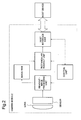
- FIG. 1 The basic structure of the present invention is shown in FIG. 1 .
- a camera module has a sensor, and converts the image formed in a sensor by a built-in lens or an external lens to digital data (image data).
- An input buffer is a RAM which accumulates image data that the camera module outputted.
- An image encoder has a function to encode image data in the format of storage, and JPEG encoder and the like is used.
- An output buffer is a memory which outputs encoded image data.
- a control unit is a program or a system which controls each part according to the operation and the like by a user.
- FIG. 1 The structure itself of FIG. 1 is the same as a general image capturing device.
- an input buffer of a general configuration requires the size of one picture
- the input buffer of the present invention should prepare only the size of one picture divided by the number of the division (described later) , according to the number the division.
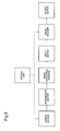
- FIG. 2 shows a structure of a camera module.
- a sensor is a component which captures an image and converts into an electrical signal, and such as CCD and CMOS are known as a converting system.
- a lens has a function to form an image of incident ray on a sensor.
- the lens may be external.
- a readout, image processing unit generates image data (raster image) by converting and processing a signal that is readout from the sensor.
- An image RAM is a RAM which holds generated image data. The size of one picture is required for the image RAM.
- a rectangular readout unit has a function to cut out arbitrary rectangular areas designated by a control unit from an image (of one picture) stored in the image RAM, and to give to a host interface.
- the host interface has a function to receive the direction from a host device (in this embodiment, the image capturing device), and a function to transfer an image to the host device.
- the control unit is a program or a system which controls each part under the direction from the host device.
- introduction of the rectangular readout unit is the characteristic feature of the present invention. With this feature, it is possible to acquire the image by each one part.
- Other parts other than the one described are of general configuration, and are usually realized by DSP and the like that is built into the camera module.
- FIG.3 is the structure of an image encoder.
- the image encoder of the present invention divides a general encode process into a partial encoder and a stream combining processes. Furthermore, in order to encode an image by each part, it has a partial stream holding buffer to hold an intermediate result.
- the partial encoder is a process configured as to encode one part of an image when only that one part of an image is inputted.
- an image is divided into small blocks (such as 16 x16 pixel), each of which is encoded to construct a stream data with a header.
- the partial encoder is equivalent to the encoding process of each block extracted from the above method, and has a function to perform the encode processing of each block included in an inputted image and to write the intermediate result in a memory.
- the stream combining process has a function of adding a header by having the configuration as the intermediate result stored in the partial stream holding buffer as one stream.
- the partial stream holding buffer Since the partial stream holding buffer holds an encoded image, not a raster image, the partial stream holding buffer should keep only the capacity according to the size after an encoding. Typically, it is about 1Mbyte to 2Mbyte in a JPEG image of 5Mpixel. Furthermore, the partial stream holding buffer and an output buffer may be in common.
- control unit gives a capturing direction to the camera module, the camera module acquires a sensor image, and generates an image on an image RAM inside the camera module.
- FIG. 4 is an example of having a division processing of an image with a division number 3.
- a control unit directs the elimination of the image and disconnection of the power to a camera module, and completes the process by storing the encoded image data to an external storage device and the like if necessary.
- FIG. 4 Although it is divided in a horizontally long reed shape in FIG. 4 , it may be divided vertically long or in both horizontal and vertical direction. However, in general, to divide in a horizontally long reed shape is easier to implement. This is because the original processing of an image encoding of each line from top to bottom is processed from left to right. In the present invention, by putting rotational process of acquiring an image to an intermediate from a camera module and an image encode processing into a form of possible division process, it is possible to capture a large sized image while reducing the amount of requirement of a memory capacity.
- FIG. 5 Another embodiment of the present invention is shown in FIG. 5 .
- the configuration shown in FIG. 5 is constructed by adding a function of rotating and encoding an image to the configuration described in FIG. 1 . This is useful when a camera module is set in inclined position due to the convenience and the like of an implemented area in the image capturing device.
- FIG. 5 an intermediate buffer and an image rotational process are added to FIG. 1 .
- the image rotational process is simply a process just to rotate an image and it can be configured by a general method.
- the image outputted from a camera module is once stored in an intermediate buffer, and is stored in an input buffer via an image rotational process in this embodiment.
- an image is divided in a horizontal direction on an image RAM of the camera module.
- a capacity of the intermediate buffer and the input buffer is determined as follows.
- the length of the divided side horizontal width on the image RAM ö the number of the division
- the capacity of the intermediate buffer the length of the divided side ⁇ the capacity that can store an image of the length of the divided side
- the capacity of the input buffer longitudinal width on the image RAM ⁇ the capacity that can store an image of the length of the divided side
- the operation after a generation of an image to an image RAM inside a camera module is as follows.
- a square area corresponding to the length of the divided side x the length of the divided size is acquired from the camera module.
- the image data acquired will be stored in an intermediate buffer.
- the image of the intermediate buffer is rotated in an image rotational process, and stored in an input buffer.
- the squared area is stored in order to be stored in the input buffer in the rotated state of the divided area.
- the image stored in the input buffer is partially encoded by a partial encoder of an image encoder.
- the result of the encoding is stored in a partial stream holding buffer.
- a process of realizing a function of a device may be performed by having the device to read the program for realizing a function of an image capturing device.
- the program thereof may be transmitted to other computer systems by a CD-ROM that is computer readable recording medium, or a magneto optical disk, or an internet being as a transmission medium, or a transmitted wave via telephone lines and the like.
- the present invention is applicable to an image capturing device capturing an image (still image or moving image).
Landscapes
- Engineering & Computer Science (AREA)
- Multimedia (AREA)
- Signal Processing (AREA)
- Compression Or Coding Systems Of Tv Signals (AREA)
- Studio Devices (AREA)
- Editing Of Facsimile Originals (AREA)
- Compression Of Band Width Or Redundancy In Fax (AREA)
Abstract
Description
- The present invention relates to a technology of capturing of a large sized image with a small capacity of a memory in an image capturing device of capturing an image (still image or moving image).
- The image size being possible of capturing has become growing steadily with the increasing function of an image capturing device, especially of a still image capturing device (camera).
- Here, the technology which can easily get correlation between divided image data obtained from dividing an image and image information on divided image data thereof is proposed. The technology includes a buffer memory, an image signal generating unit that generates readout signal by dividing an image from the buffer memory, an image information generating unit that generates image information of an image that is divided and readout, a multiplexing unit that multiplexes the image signal and the image information, a synchronization code detecting unit that separates the divided image data and the image information from the multiplexed image signal, an image encoding unit that encodes the separated divided image data, and a multiplexing unit that multiplexes the separated image information and an encoded bit stream (for example, refer to patent document 1).
- Patent document 1: Japanese Patent Laid-Open No.
2000-244912 - However, since the image encode processing is performed after all images are obtained in the related technology, a large memory as much as for the image size in the image capturing device is necessary, and the large amount of capacity with the increase of an image size has made difficult on the implement.
- Especially, when a rotation is required, memory for two images is required before and after the rotation (because the original image cannot be processed by the form of replacement in a rotational process), therefore the capacity required will increase further.
- It is an object of the present invention to provide an image capturing device, encoding method, and program that can reduce the capacity of a memory necessary for a process even if capturing of a large sized image is required.
- In order to achieve the object, the present invention will have the following features.
- The image capturing device of the present invention comprises a division transfer means for individually outputting arbitrary rectangular areas in captured images, a division encoding means for encoding the data from the said division transfer means using a partial encoder, and an combining means for combining the encoded data at the end.
- Furthermore, the encoding method of the present invention comprises a division transfer step for individually outputting arbitrary rectangular areas in captured images, a division encoding step for encoding the data from the said division transfer means using a partial encoder, and an combining step for combining the encoded data at the end.
- Furthermore, the program of the present invention is characterized by comprising a division transfer step for individually outputting arbitrary rectangular areas in captured images, a division encoding step for encoding the data from the said division transfer means using a partial encoder, and an combining step for combining the encoded data at the end.
- According to the present invention, even when the capturing of a large sized image is required, the capacity of a memory required for processing can be reduced.
- Hereinafter, preferred embodiments of the present invention will be described in detail with referent to the drawings. The basic structure of the present invention is shown in
FIG. 1 . - A camera module has a sensor, and converts the image formed in a sensor by a built-in lens or an external lens to digital data (image data).
- An input buffer is a RAM which accumulates image data that the camera module outputted.
- An image encoder has a function to encode image data in the format of storage, and JPEG encoder and the like is used.
- An output buffer is a memory which outputs encoded image data.
- A control unit is a program or a system which controls each part according to the operation and the like by a user.
- The structure itself of
FIG. 1 is the same as a general image capturing device. However, although an input buffer of a general configuration requires the size of one picture, the input buffer of the present invention should prepare only the size of one picture divided by the number of the division (described later) , according to the number the division. - As a typical example, when an image of 5Mpixel with 16bit/pixel is divided into three parts, only 1.67Mpixel (3.3Mbyte) is required according to the method of the present invention whereas normally 5Mpixel (10Mbyte) would be required.
-
FIG. 2 shows a structure of a camera module. A sensor is a component which captures an image and converts into an electrical signal, and such as CCD and CMOS are known as a converting system. - A lens has a function to form an image of incident ray on a sensor. The lens may be external.
- A readout, image processing unit generates image data (raster image) by converting and processing a signal that is readout from the sensor.
- An image RAM is a RAM which holds generated image data. The size of one picture is required for the image RAM.
- A rectangular readout unit has a function to cut out arbitrary rectangular areas designated by a control unit from an image (of one picture) stored in the image RAM, and to give to a host interface.
- The host interface has a function to receive the direction from a host device (in this embodiment, the image capturing device), and a function to transfer an image to the host device.
- The control unit is a program or a system which controls each part under the direction from the host device.
- Among the configuration of
FIG.2 , introduction of the rectangular readout unit is the characteristic feature of the present invention. With this feature, it is possible to acquire the image by each one part. Other parts other than the one described are of general configuration, and are usually realized by DSP and the like that is built into the camera module. -
FIG.3 is the structure of an image encoder. The image encoder of the present invention divides a general encode process into a partial encoder and a stream combining processes. Furthermore, in order to encode an image by each part, it has a partial stream holding buffer to hold an intermediate result. - The partial encoder is a process configured as to encode one part of an image when only that one part of an image is inputted.
- In a general image encoding method (JPEG, etc.), an image is divided into small blocks (such as 16 x16 pixel), each of which is encoded to construct a stream data with a header.
- The partial encoder is equivalent to the encoding process of each block extracted from the above method, and has a function to perform the encode processing of each block included in an inputted image and to write the intermediate result in a memory.
- The stream combining process has a function of adding a header by having the configuration as the intermediate result stored in the partial stream holding buffer as one stream.
- Since the partial stream holding buffer holds an encoded image, not a raster image, the partial stream holding buffer should keep only the capacity according to the size after an encoding. Typically, it is about 1Mbyte to 2Mbyte in a JPEG image of 5Mpixel. Furthermore, the partial stream holding buffer and an output buffer may be in common.
- Next, an operation of this embodiment will be described. First, the control unit gives a capturing direction to the camera module, the camera module acquires a sensor image, and generates an image on an image RAM inside the camera module.
- Next, by the method shown in
FIG. 4 , up to the generation of encoded image data is performed. In the present invention, an image is processed by dividing into a designated number by a division number.FIG. 4 is an example of having a division processing of an image with adivision number 3. - Each part being divided will be processed as follows.
- (1) One area divided from a camera module is acquired. The acquired data is stored in an input buffer.
- (2) By the partial encoder of an image encoder, an image stored in an input buffer is partially encoded. The result of the encoding is stored in a partial stream holding buffer. At this point, it is a partial stream and because a header is not added yet, it is in an incomplete state as an encoded image data.
- (3) (1) ∼ (2) is repeated as many times as the division number.
- (4) By the stream concatenation process of an image encoder, partial streams stored in the partial stream holding buffer are combined. The combined stream is outputted to an output buffer as the encoded data, to which a header is added.
- After the all of the above is being performed, a control unit directs the elimination of the image and disconnection of the power to a camera module, and completes the process by storing the encoded image data to an external storage device and the like if necessary.
- Further, although it is divided in a horizontally long reed shape in
FIG. 4 , it may be divided vertically long or in both horizontal and vertical direction. However, in general, to divide in a horizontally long reed shape is easier to implement. This is because the original processing of an image encoding of each line from top to bottom is processed from left to right. In the present invention, by putting rotational process of acquiring an image to an intermediate from a camera module and an image encode processing into a form of possible division process, it is possible to capture a large sized image while reducing the amount of requirement of a memory capacity. - Another embodiment of the present invention is shown in
FIG. 5 . The configuration shown inFIG. 5 is constructed by adding a function of rotating and encoding an image to the configuration described inFIG. 1 . This is useful when a camera module is set in inclined position due to the convenience and the like of an implemented area in the image capturing device. - In
FIG. 5 , an intermediate buffer and an image rotational process are added toFIG. 1 . The image rotational process is simply a process just to rotate an image and it can be configured by a general method. - Unlike the case in
FIG. 1 , the image outputted from a camera module is once stored in an intermediate buffer, and is stored in an input buffer via an image rotational process in this embodiment. - According to this embodiment, an image is divided in a horizontal direction on an image RAM of the camera module. Depending on the division number, a capacity of the intermediate buffer and the input buffer is determined as follows.
- The length of the divided side = horizontal width on the image RAM ö the number of the division


- Referring now to
FIG. 6 , an operation of this embodiment is shown. The operation after a generation of an image to an image RAM inside a camera module is as follows. - First, a square area corresponding to the length of the divided side x the length of the divided size is acquired from the camera module. The image data acquired will be stored in an intermediate buffer.
- Next, the image of the intermediate buffer is rotated in an image rotational process, and stored in an input buffer. At this time, the squared area is stored in order to be stored in the input buffer in the rotated state of the divided area.
- The above-mentioned two steps are repeated as many times as the longitudinal width ö the division number, on the image RAM.
- Then, the image stored in the input buffer is partially encoded by a partial encoder of an image encoder. The result of the encoding is stored in a partial stream holding buffer.
- The above-mentioned four steps are repeated as many times as the number of the division.
- Finally, by the stream concatenation process of an image encoder, partial streams stored in the partial stream holding buffer are combined. The combined stream is outputted to an output buffer as the encoded data, to which a header is added.
- As described above, even when a rotation is necessary, by adding a small capacity of a memory according to the number of the division to the intermediate buffer, the function of encoding by rotating can be realized.
- According to this embodiment, even if the capturing of a large sized image is required, the capacity of a memory required for processing, and especially, the additional capacity of a memory required for the rotation can be reduced.
- In addition, each embodiment mentioned above is the preferred embodiment of the present invention, and various changes can be made without departing from the scope of the invention. For example, a process of realizing a function of a device may be performed by having the device to read the program for realizing a function of an image capturing device. Further, the program thereof may be transmitted to other computer systems by a CD-ROM that is computer readable recording medium, or a magneto optical disk, or an internet being as a transmission medium, or a transmitted wave via telephone lines and the like.
- In addition, this application claims the priority of Japanese patent application No.
2007-303094 filed on Nov. 22, 2007 - The present invention, for example, is applicable to an image capturing device capturing an image (still image or moving image).
-
-
FIG. 1 is a diagram showing a configuration according to the embodiment of the present invention; -
FIG.2 is a diagram showing a configuration of a module according to the embodiment of the present invention; -
FIG. 3 is a diagram showing a configuration of an image encoder according to the embodiment of the present invention; -
FIG. 4 is a diagram showing up to a generation of encoded image data according to the embodiment of the present invention; -
FIG. 5 is a diagram showing the other embodiment of the present invention; and -
FIG. 6 is a diagram showing an operation according to the other embodiment of the present invention.
Claims (6)
- An image capturing device comprising:a division transfer means for individually outputting arbitrary rectangular areas in captured images;a division encoding means for encoding the data from said division transfer means using a partial encoder; anda combining means for combining the encoded data at the end.
- The image capturing device of claim 1 further comprising a rotational process means for performing a rotational process of an image data outputted by said division transfer means.
- An encoding method comprising:a division transfer step for individually outputting arbitrary rectangular areas in captured images;a division encoding step for encoding the data from said division transfer means using a partial encoder; anda combining step for combining the encoded data at the end.
- The encoding method of claim 3 further comprising a step for performing a rotational process of an image data outputted by said division transfer step.
- A program performing:a division transfer step for individually outputting arbitrary rectangular areas in captured images to a computer;a division encoding step for encoding the data from said division transfer means using a partial encoder; anda combining step for combining the encoded data at the end.
- The program of claim 5 further performing a step for a rotational process of an image data outputted by said division transfer step.
Applications Claiming Priority (2)
| Application Number | Priority Date | Filing Date | Title |
|---|---|---|---|
| JP2007303094 | 2007-11-22 | ||
| PCT/JP2008/070819 WO2009066626A1 (en) | 2007-11-22 | 2008-11-14 | Image capturing device, encoding method, and program |
Publications (2)
| Publication Number | Publication Date |
|---|---|
| EP2200318A1 true EP2200318A1 (en) | 2010-06-23 |
| EP2200318A4 EP2200318A4 (en) | 2013-05-22 |
Family
ID=40667449
Family Applications (1)
| Application Number | Title | Priority Date | Filing Date |
|---|---|---|---|
| EP20080852720 Ceased EP2200318A4 (en) | 2007-11-22 | 2008-11-14 | IMAGE CAPTURE DEVICE, ENCODING METHOD, AND PROGRAM |
Country Status (5)
| Country | Link |
|---|---|
| US (1) | US20100225778A1 (en) |
| EP (1) | EP2200318A4 (en) |
| JP (1) | JP5187316B2 (en) |
| CN (1) | CN101874408A (en) |
| WO (1) | WO2009066626A1 (en) |
Families Citing this family (1)
| Publication number | Priority date | Publication date | Assignee | Title |
|---|---|---|---|---|
| WO2010123976A1 (en) * | 2009-04-21 | 2010-10-28 | Tetrasun, Inc. | Method for forming structures in a solar cell |
Family Cites Families (18)
| Publication number | Priority date | Publication date | Assignee | Title |
|---|---|---|---|---|
| JPH08116534A (en) * | 1994-10-18 | 1996-05-07 | Seiko Epson Corp | Image data encoding apparatus and method, and image data decoding apparatus and method |
| JPH10234043A (en) * | 1997-02-20 | 1998-09-02 | Toshiba Corp | Video encoding / decoding device |
| JP3177473B2 (en) * | 1997-03-28 | 2001-06-18 | 三洋電機株式会社 | Digital imaging device |
| US6624761B2 (en) * | 1998-12-11 | 2003-09-23 | Realtime Data, Llc | Content independent data compression method and system |
| JP2000244912A (en) * | 1999-02-17 | 2000-09-08 | Matsushita Electric Ind Co Ltd | Image encoding device and image decoding device |
| JP3701522B2 (en) * | 1999-09-21 | 2005-09-28 | シャープ株式会社 | Image encoding apparatus, image encoding method, and computer-readable recording medium |
| JP3743384B2 (en) * | 2002-04-19 | 2006-02-08 | ソニー株式会社 | Image encoding apparatus and method, and image decoding apparatus and method |
| FI114679B (en) * | 2002-04-29 | 2004-11-30 | Nokia Corp | Direct access points for video coding |
| JP4189252B2 (en) * | 2003-04-02 | 2008-12-03 | パナソニック株式会社 | Image processing apparatus and camera |
| JP4409897B2 (en) * | 2003-09-19 | 2010-02-03 | 株式会社リコー | Image processing apparatus, image processing method, program, and information recording medium |
| KR100703283B1 (en) * | 2004-03-15 | 2007-04-03 | 삼성전자주식회사 | Image coding apparatus and method for predicting motion through rotation matching |
| JP4579613B2 (en) * | 2004-08-04 | 2010-11-10 | キヤノン株式会社 | Image processing apparatus and method, and imaging apparatus |
| JP2006333436A (en) * | 2005-01-07 | 2006-12-07 | Ntt Docomo Inc | Moving picture encoding apparatus, moving picture decoding apparatus, moving picture encoding method, moving picture decoding method, moving picture encoding program, and moving picture decoding program |
| KR20060123939A (en) * | 2005-05-30 | 2006-12-05 | 삼성전자주식회사 | Method and apparatus for image encoding |
| JP4974619B2 (en) * | 2005-11-09 | 2012-07-11 | キヤノン株式会社 | Image data processing apparatus, image data processing method, program, and recording medium |
| JP4273426B2 (en) * | 2005-12-07 | 2009-06-03 | ソニー株式会社 | Image processing method, image processing apparatus, program for image processing method, and recording medium recording program for image processing method |
| JP4662880B2 (en) * | 2006-04-03 | 2011-03-30 | 三星電子株式会社 | Imaging apparatus and imaging method |
| JP4833728B2 (en) | 2006-05-09 | 2011-12-07 | 住友ゴム工業株式会社 | Antistatic coating floor and coating agent |
-
2008
- 2008-11-14 JP JP2009542540A patent/JP5187316B2/en not_active Expired - Fee Related
- 2008-11-14 US US12/738,012 patent/US20100225778A1/en not_active Abandoned
- 2008-11-14 CN CN200880117499A patent/CN101874408A/en active Pending
- 2008-11-14 EP EP20080852720 patent/EP2200318A4/en not_active Ceased
- 2008-11-14 WO PCT/JP2008/070819 patent/WO2009066626A1/en not_active Ceased
Also Published As
| Publication number | Publication date |
|---|---|
| EP2200318A4 (en) | 2013-05-22 |
| WO2009066626A1 (en) | 2009-05-28 |
| JP5187316B2 (en) | 2013-04-24 |
| US20100225778A1 (en) | 2010-09-09 |
| JPWO2009066626A1 (en) | 2011-04-07 |
| CN101874408A (en) | 2010-10-27 |
Similar Documents
| Publication | Publication Date | Title |
|---|---|---|
| US6784941B1 (en) | Digital camera with video input | |
| KR101395433B1 (en) | Imaging device and imaging method | |
| KR20020047069A (en) | Device and Method for transmitting picture data | |
| US7433543B2 (en) | Image processing apparatus and method, and image sensing apparatus | |
| CN100388752C (en) | Imaging device and processing method thereof | |
| US7277586B2 (en) | Images combination processing system, images combination processing method, and images combination processing program | |
| US8922676B2 (en) | Video frame buffer | |
| US20100225778A1 (en) | Image capturing device, encoding method, and program | |
| US20050253878A1 (en) | Image display device | |
| JP5011289B2 (en) | Imaging device | |
| JP2023179473A (en) | Imaging device, imaging device, operating method of the imaging device, and program | |
| KR101541123B1 (en) | Image data output appratus for image signal processor | |
| JP4244218B2 (en) | Imaging signal processing circuit and camera system | |
| US7787701B2 (en) | Image processing apparatus and apparatus connected to image processing apparatus | |
| US20250211782A1 (en) | Video compression apparatus, decompression apparatus and recording medium | |
| US11616929B2 (en) | Electronic apparatus and method of controlling the same, and storage medium | |
| JP2006165666A (en) | Surveillance camera, surveillance image monitor device, surveillance image storage device, and surveillance system | |
| KR100402927B1 (en) | How to Display Multiple Screens of Digital Cameras | |
| KR20090071321A (en) | Imaging device, imaging method and storage medium recording computer program for performing the same | |
| KR20260053968A (en) | Encoder, decoder, and image processing system | |
| KR101676400B1 (en) | Camera apparatus and method for providing recorded image | |
| JPH0944634A (en) | Video input device | |
| KR20060077161A (en) | Image sensor and image scaling down method | |
| CN115474061A (en) | Image data transmission method, device, terminal equipment and storage medium | |
| JPH09322070A (en) | Image input device |
Legal Events
| Date | Code | Title | Description |
|---|---|---|---|
| PUAI | Public reference made under article 153(3) epc to a published international application that has entered the european phase |
Free format text: ORIGINAL CODE: 0009012 |
|
| 17P | Request for examination filed |
Effective date: 20100331 |
|
| AK | Designated contracting states |
Kind code of ref document: A1 Designated state(s): AT BE BG CH CY CZ DE DK EE ES FI FR GB GR HR HU IE IS IT LI LT LU LV MC MT NL NO PL PT RO SE SI SK TR |
|
| AX | Request for extension of the european patent |
Extension state: AL BA MK RS |
|
| DAX | Request for extension of the european patent (deleted) | ||
| A4 | Supplementary search report drawn up and despatched |
Effective date: 20130423 |
|
| RIC1 | Information provided on ipc code assigned before grant |
Ipc: H04N 7/26 20060101AFI20130417BHEP Ipc: H04N 1/41 20060101ALI20130417BHEP Ipc: H04N 5/232 20060101ALI20130417BHEP Ipc: H04N 7/30 20060101ALI20130417BHEP Ipc: H04N 1/387 20060101ALI20130417BHEP Ipc: H04N 5/225 20060101ALI20130417BHEP |
|
| RAP1 | Party data changed (applicant data changed or rights of an application transferred) |
Owner name: LENOVO INNOVATIONS LIMITED (HONG KONG) |
|
| 17Q | First examination report despatched |
Effective date: 20160615 |
|
| STAA | Information on the status of an ep patent application or granted ep patent |
Free format text: STATUS: EXAMINATION IS IN PROGRESS |
|
| STAA | Information on the status of an ep patent application or granted ep patent |
Free format text: STATUS: THE APPLICATION HAS BEEN REFUSED |
|
| REG | Reference to a national code |
Ref country code: DE Ref legal event code: R003 |
|
| 18R | Application refused |
Effective date: 20180204 |