EP2200066A1 - Switch arrangement for medium and high-voltage switching devices - Google Patents
Switch arrangement for medium and high-voltage switching devices Download PDFInfo
- Publication number
- EP2200066A1 EP2200066A1 EP08021978A EP08021978A EP2200066A1 EP 2200066 A1 EP2200066 A1 EP 2200066A1 EP 08021978 A EP08021978 A EP 08021978A EP 08021978 A EP08021978 A EP 08021978A EP 2200066 A1 EP2200066 A1 EP 2200066A1
- Authority
- EP
- European Patent Office
- Prior art keywords
- switch
- switch arrangement
- ignition
- arrangement
- propelling charge
- Prior art date
- Legal status (The legal status is an assumption and is not a legal conclusion. Google has not performed a legal analysis and makes no representation as to the accuracy of the status listed.)
- Granted
Links
Images

Classifications
-
- H—ELECTRICITY
- H01—ELECTRIC ELEMENTS
- H01H—ELECTRIC SWITCHES; RELAYS; SELECTORS; EMERGENCY PROTECTIVE DEVICES
- H01H39/00—Switching devices actuated by an explosion produced within the device and initiated by an electric current
-
- H—ELECTRICITY
- H01—ELECTRIC ELEMENTS
- H01H—ELECTRIC SWITCHES; RELAYS; SELECTORS; EMERGENCY PROTECTIVE DEVICES
- H01H79/00—Protective switches in which excess current causes the closing of contacts, e.g. for short-circuiting the apparatus to be protected
-
- H—ELECTRICITY
- H01—ELECTRIC ELEMENTS
- H01H—ELECTRIC SWITCHES; RELAYS; SELECTORS; EMERGENCY PROTECTIVE DEVICES
- H01H39/00—Switching devices actuated by an explosion produced within the device and initiated by an electric current
- H01H39/004—Closing switches
-
- H—ELECTRICITY
- H01—ELECTRIC ELEMENTS
- H01H—ELECTRIC SWITCHES; RELAYS; SELECTORS; EMERGENCY PROTECTIVE DEVICES
- H01H71/00—Details of the protective switches or relays covered by groups H01H73/00 - H01H83/00
- H01H71/10—Operating or release mechanisms
- H01H71/1045—Multiple circuits-breaker, e.g. for the purpose of dividing current or potential drop
Definitions
- the invention relates to a switch arrangement for medium and high-voltage switching devices having switches, in which at least one of the contacts is a moving contact which can be actuated by means of an ignition charge, according to the pre-characterizing clause of patent claim 1.
- a short-circuit device has already been disclosed in DE 102 54 497 B3 in which a propelling charge is provided for moving the moving contact. An effective and mechanically very fast contact closure can be achieved in this way.
- the invention is therefore based on the object of further developing a switch arrangement of this kind to the effect that both a high-current arrangement and a high-voltage arrangement can be taken into account.
- the heart of the invention is that, for a plurality of switches, a dedicated ignition device is provided for each switch, and that the ignition devices are coupled together with regard to the time of the ignition. This achieves synchronous ignition.
- the first relates to a short-circuit device arrangement in high-current design.
- a second relates to a short-circuit device arrangement in high-voltage design.
- the propelling charges or primers are galvanically isolated from one another.
- An exemplary embodiment here is that the propelling charge of the second switch is ignited by means of a photoelectric device.
- the photo section provides galvanic isolation.
- each moving contact is connected to a piston-cylinder unit in which one or more propelling charges are arranged.
- a gas-tight membrane which is punctured by the piston at intended breakpoints when the propelling charge is ignited, is provided between piston and contact piece.
- At least the chambers in which the switching path lies are vacuum chambers.
- the moving contacts are designed with a conical shape and that the respective fixed contacts are provided with an inner cone in a complementary manner.
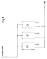
- Figure 1 shows the arrangement of a plurality of parallel connected short-circuit devices 1, 2, ..., 5.
- Each of these short-circuit devices has a moving contact and a fixed contact.
- the parallel connection in its entirety results in the high-current version, or the version with the high effective current carrying capacity.
- the respective moving contact is in each case driven by a propelling charge.
- the propelling charges of all parallel connected short-circuit devices are controlled synchronously in time by means of a common ignition device.
- Figure 2 shows a series circuit of short-circuit devices. This results in the high-voltage version. In this version, the voltage is divided. Although a common ignition device is also provided here in order to achieve potential isolation, only one of the short-circuit devices, i.e. the primer/propelling charge of one of the short-circuit devices, can be controlled directly, while the control of the primer/propelling charge of the second short-circuit device must be potentially isolated. This can be achieved by interposing either a pulse transformer or a photoelectric section in the ignition line.
Landscapes
- Keying Circuit Devices (AREA)
- Electronic Switches (AREA)
- Driving Mechanisms And Operating Circuits Of Arc-Extinguishing High-Tension Switches (AREA)
- Gas-Insulated Switchgears (AREA)
- Push-Button Switches (AREA)
Abstract
Description
- The invention relates to a switch arrangement for medium and high-voltage switching devices having switches, in which at least one of the contacts is a moving contact which can be actuated by means of an ignition charge, according to the pre-characterizing clause of patent claim 1.
- A short-circuit device has already been disclosed in
DE 102 54 497 B3 in which a propelling charge is provided for moving the moving contact. An effective and mechanically very fast contact closure can be achieved in this way. - However, the high-voltage and high-current case must be considered separately.
- The invention is therefore based on the object of further developing a switch arrangement of this kind to the effect that both a high-current arrangement and a high-voltage arrangement can be taken into account.
- The object set is achieved according to the invention by the characterizing features of claim 1.
- Further advantageous embodiments are specified in the dependent claims.
- The heart of the invention is that, for a plurality of switches, a dedicated ignition device is provided for each switch, and that the ignition devices are coupled together with regard to the time of the ignition. This achieves synchronous ignition.
- Accordingly there are two alternative arrangements. The first relates to a short-circuit device arrangement in high-current design.
A second relates to a short-circuit device arrangement in high-voltage design. - With regard to the first alternative, it is arranged that two or more independent switches are connected in parallel, and that the propelling charge for each switch can be applied by means of a common ignition device. This makes it possible to achieve synchronous short-circuiting, resulting in a high effective current carrying capacity due to the parallel circuit.
- With regard to the second alternative, it is specified that two or more independent switches are connected in series, and that the propelling charge of the first switch can be directly electrically ignited, while the propelling charge or the electrical ignition of the second or following switch is galvanically isolated from the first. This series circuit results in a high effective dielectric strength. However, with the series circuit, annoying increases can occur in the potential of the respective propelling charges due to marginally different ignition times.
- In order to avoid this, the propelling charges or primers are galvanically isolated from one another. An exemplary embodiment here is that the propelling charge of the second switch is ignited by means of a photoelectric device. The photo section provides galvanic isolation.
- In a further advantageous arrangement, it is specified that each moving contact is connected to a piston-cylinder unit in which one or more propelling charges are arranged.
- Furthermore, it is advantageously arranged that a gas-tight membrane, which is punctured by the piston at intended breakpoints when the propelling charge is ignited, is provided between piston and contact piece.
- In a further advantageous arrangement, it is specified that at least the chambers in which the switching path lies are vacuum chambers.
- Furthermore, it is advantageously arranged that in each case a plurality of metallic screen elements, which are each separated from one another by a gap, are provided around each moving contact along the switching path.
- In a final advantageous embodiment, it is specified that the moving contacts are designed with a conical shape and that the respective fixed contacts are provided with an inner cone in a complementary manner.
- The two alternatives are shown in the drawing.
- In the drawing:
-
Figure 1 : shows the high-current version -
Figure 2 : shows the high-voltage version -
Figure 1 shows the arrangement of a plurality of parallel connected short-circuit devices 1, 2, ..., 5. Each of these short-circuit devices has a moving contact and a fixed contact. The parallel connection in its entirety results in the high-current version, or the version with the high effective current carrying capacity. Here, the respective moving contact is in each case driven by a propelling charge. The propelling charges of all parallel connected short-circuit devices are controlled synchronously in time by means of a common ignition device. - In contrast,
Figure 2 shows a series circuit of short-circuit devices. This results in the high-voltage version. In this version, the voltage is divided. Although a common ignition device is also provided here in order to achieve potential isolation, only one of the short-circuit devices, i.e. the primer/propelling charge of one of the short-circuit devices, can be controlled directly, while the control of the primer/propelling charge of the second short-circuit device must be potentially isolated. This can be achieved by interposing either a pulse transformer or a photoelectric section in the ignition line. -
- 1, ..., 5
- Short-circuit device
- 10
- Potential isolator/Pulse transformer
- 11
- Photoelectric section
- 100
- Ignition device
Claims (9)
- A switch arrangement for medium and high-voltage switching devices having switches, in which at least one of the contacts is a moving contact which can be actuated by means of an ignition charge, wherein, for a plurality of switches, a dedicated ignition device is provided for each switch, and the ignition devices are coupled together with regard to the time of the ignition.
- The switch arrangement as claimed in claim 1, wherein two or more independent switches are connected in parallel, and the propelling charge for each switch can be applied by means of a common ignition device.
- The switch arrangement as claimed in claim 1, wherein two or more independent switches are connected in series, and the propelling charge of the first switch can be directly electrically ignited, while the propelling charge or the electrical ignition of the second or following switch is galvanically isolated from the first.
- The switch arrangement as claimed in claim 3, wherein the propelling charge of the second switch is ignited by means of a photoelectric device.
- The switch arrangement as claimed in claim 2 or 3, wherein each moving contact is connected to a piston-cylinder unit in which one or more propelling charges are arranged.
- The switch arrangement as claimed in claim 2 or 3, wherein a gas-tight membrane, which is punctured by the piston at intended breakpoints when the propelling charge is ignited, is provided between piston and contact piece.
- The switch arrangement as claimed in one of the preceding claims, wherein at least the chambers in which the switching path lies are vacuum chambers.
- The switch arrangement as claimed in one of the preceding claims, wherein in each case a plurality of metallic screen elements, which are each separated from one another by a gap, are provided around each moving contact along the switching path.
- The switch arrangement as claimed in one of the preceding claims, wherein the moving contacts are designed with a conical shape and the respective fixed contacts are provided with an inner cone in a complementary manner.
Priority Applications (13)
| Application Number | Priority Date | Filing Date | Title |
|---|---|---|---|
| ES08021978.5T ES2440725T3 (en) | 2008-12-18 | 2008-12-18 | Switch arrangement for medium and high voltage switching devices |
| EP08021978.5A EP2200066B1 (en) | 2008-12-18 | 2008-12-18 | Switch arrangement for medium and high-voltage switching devices |
| MX2011006285A MX2011006285A (en) | 2008-12-18 | 2009-12-14 | Switch arrangement for medium and high-voltage switching devices. |
| RU2011129673/07A RU2530541C2 (en) | 2008-12-18 | 2009-12-14 | Switching circuit for medium- and high-voltage devices |
| JP2011541183A JP5490136B2 (en) | 2008-12-18 | 2009-12-14 | Switching device for medium and high voltage switching elements |
| PCT/EP2009/008927 WO2010078918A1 (en) | 2008-12-18 | 2009-12-14 | Switch arrangement for medium and high-voltage switching devices |
| KR1020117013536A KR101389341B1 (en) | 2008-12-18 | 2009-12-14 | Switch arrangement for medium and high-voltage switching devices |
| UAA201107656A UA108737C2 (en) | 2008-12-18 | 2009-12-14 | HIGH voltage switch off BLOCK |
| BRPI0923435A BRPI0923435A2 (en) | 2008-12-18 | 2009-12-14 | switching system for medium and high voltage switching devices |
| CN200980150756.1A CN102257589B (en) | 2008-12-18 | 2009-12-14 | Switch arrangement for medium and high-voltage switching devices |
| EG2011060980A EG26570A (en) | 2008-12-18 | 2011-06-14 | Switch arangement for medium and high-voltage switching devices |
| ZA2011/04449A ZA201104449B (en) | 2008-12-18 | 2011-06-15 | Switch arrangement for medium and high-voltage switching devices |
| US13/164,286 US8525052B2 (en) | 2008-12-18 | 2011-06-20 | Switch arrangement for medium and high-voltage switching devices |
Applications Claiming Priority (1)
| Application Number | Priority Date | Filing Date | Title |
|---|---|---|---|
| EP08021978.5A EP2200066B1 (en) | 2008-12-18 | 2008-12-18 | Switch arrangement for medium and high-voltage switching devices |
Publications (2)
| Publication Number | Publication Date |
|---|---|
| EP2200066A1 true EP2200066A1 (en) | 2010-06-23 |
| EP2200066B1 EP2200066B1 (en) | 2013-10-16 |
Family
ID=40577861
Family Applications (1)
| Application Number | Title | Priority Date | Filing Date |
|---|---|---|---|
| EP08021978.5A Active EP2200066B1 (en) | 2008-12-18 | 2008-12-18 | Switch arrangement for medium and high-voltage switching devices |
Country Status (13)
| Country | Link |
|---|---|
| US (1) | US8525052B2 (en) |
| EP (1) | EP2200066B1 (en) |
| JP (1) | JP5490136B2 (en) |
| KR (1) | KR101389341B1 (en) |
| CN (1) | CN102257589B (en) |
| BR (1) | BRPI0923435A2 (en) |
| EG (1) | EG26570A (en) |
| ES (1) | ES2440725T3 (en) |
| MX (1) | MX2011006285A (en) |
| RU (1) | RU2530541C2 (en) |
| UA (1) | UA108737C2 (en) |
| WO (1) | WO2010078918A1 (en) |
| ZA (1) | ZA201104449B (en) |
Cited By (2)
| Publication number | Priority date | Publication date | Assignee | Title |
|---|---|---|---|---|
| CN103069529A (en) * | 2010-08-02 | 2013-04-24 | 米其林集团总公司 | Device for connecting a battery to an electric or hybrid vehicle, and battery housing comprising said connection device |
| US8861144B2 (en) | 2011-11-15 | 2014-10-14 | Eaton Corporation | Triggered arc flash arrester and switchgear system including the same |
Families Citing this family (3)
| Publication number | Priority date | Publication date | Assignee | Title |
|---|---|---|---|---|
| JP5633365B2 (en) * | 2010-12-27 | 2014-12-03 | ダイキン工業株式会社 | Device operating system |
| CN105324924B (en) | 2013-04-18 | 2018-12-25 | Abb瑞士股份有限公司 | Mechanical bypass switchgear, converter arms and power converters |
| CN109860502A (en) * | 2018-12-24 | 2019-06-07 | 中国电子科技集团公司第十八研究所 | Bus bar for preventing thermal runaway diffusion and storage battery pack |
Citations (6)
| Publication number | Priority date | Publication date | Assignee | Title |
|---|---|---|---|---|
| DE1141015B (en) * | 1955-12-10 | 1962-12-13 | Calor Emag Elektrizitaets Ag | Device for the rapid interruption of short-circuit currents |
| FR1535272A (en) * | 1966-08-29 | 1968-08-02 | Asea Ab | High voltage switch |
| DE3148142A1 (en) * | 1981-12-04 | 1983-06-09 | Siemens AG, 1000 Berlin und 8000 München | Vacuum switch |
| US6657150B1 (en) | 2002-06-14 | 2003-12-02 | Eaton Corporation | Shorting switch and system to eliminate arcing faults in power distribution equipment |
| DE10254497B3 (en) | 2002-11-22 | 2004-06-03 | Moeller Gmbh | Short-circuit device for arcing protection of energy distribution network, uses energy provided by chemical reaction mixture for displacement of short-circuit contact |
| DE102006024991A1 (en) * | 2006-05-30 | 2007-12-06 | Abb Technology Ag | Method for extinguishing an arc within a medium and high voltage switchgear, as well as short-circuiting device itself |
Family Cites Families (18)
| Publication number | Priority date | Publication date | Assignee | Title |
|---|---|---|---|---|
| DE1094864B (en) | 1959-06-05 | 1960-12-15 | Siemens Ag | Short-circuiters for bridging accidental arcs in electrical medium or high voltage systems |
| SE326755B (en) | 1966-08-29 | 1970-08-03 | Asea Ab | |
| US3796888A (en) * | 1972-09-05 | 1974-03-12 | N Berry | Switch structure |
| JPS5064771A (en) * | 1973-10-04 | 1975-06-02 | ||
| DE2623816A1 (en) | 1976-05-28 | 1977-12-08 | Calor Emag Elektrizitaets Ag | Rapid earthing contact for gas insulated HV installations - has switch driven by explosive charge upon significant temp. change |
| US4182940A (en) * | 1978-08-29 | 1980-01-08 | Ford Motor Company | High voltage distributor for dual ignition system |
| DE2905747A1 (en) * | 1979-01-25 | 1980-08-07 | Bbc Brown Boveri & Cie | CURRENT LIMITATION DEVICE FOR HIGH VOLTAGE SWITCHGEAR |
| DE64581T1 (en) * | 1981-05-13 | 1983-05-11 | Deere & Co., 61265 Moline, Ill. | STARTING ARRANGEMENT FOR COMBUSTION ENGINE. |
| US4570078A (en) * | 1982-05-27 | 1986-02-11 | Honda Giken Kogyo Kabushiki Kaisha | Switch assembly for a motor vehicle |
| JPS62165652U (en) * | 1986-04-09 | 1987-10-21 | ||
| US5696164A (en) | 1994-12-22 | 1997-12-09 | Johnson & Johnson Consumer Products, Inc. | Antifungal treatment of nails |
| SE9404455L (en) | 1994-12-22 | 1996-06-23 | Asea Brown Boveri | Electrical switchgear |
| DE29503914U1 (en) | 1995-03-08 | 1996-07-04 | Klöckner-Moeller GmbH, 53115 Bonn | Arc fault detection device for switchgear for the distribution of electrical energy |
| JPH10241524A (en) * | 1997-02-28 | 1998-09-11 | Harness Sogo Gijutsu Kenkyusho:Kk | Electric circuit breaker |
| DE19746809A1 (en) | 1997-10-23 | 1999-04-29 | Kloeckner Moeller Gmbh | Short-circuiter for arcing protection device |
| JP2001021226A (en) * | 1999-07-06 | 2001-01-26 | Nichiyu Giken Kogyo Co Ltd | Self-burning agent heater |
| EP1492139B1 (en) * | 2003-06-26 | 2016-01-06 | Autoliv Development AB | Chisel for pyromechanical separator |
| DE102005048003B4 (en) * | 2005-08-04 | 2008-04-30 | Dehn + Söhne Gmbh + Co. Kg | Short-circuiting device for use in low and medium voltage systems for property and personal protection |
-
2008
- 2008-12-18 ES ES08021978.5T patent/ES2440725T3/en active Active
- 2008-12-18 EP EP08021978.5A patent/EP2200066B1/en active Active
-
2009
- 2009-12-14 JP JP2011541183A patent/JP5490136B2/en not_active Expired - Fee Related
- 2009-12-14 CN CN200980150756.1A patent/CN102257589B/en active Active
- 2009-12-14 WO PCT/EP2009/008927 patent/WO2010078918A1/en not_active Ceased
- 2009-12-14 UA UAA201107656A patent/UA108737C2/en unknown
- 2009-12-14 RU RU2011129673/07A patent/RU2530541C2/en not_active IP Right Cessation
- 2009-12-14 BR BRPI0923435A patent/BRPI0923435A2/en not_active IP Right Cessation
- 2009-12-14 KR KR1020117013536A patent/KR101389341B1/en not_active Expired - Fee Related
- 2009-12-14 MX MX2011006285A patent/MX2011006285A/en active IP Right Grant
-
2011
- 2011-06-14 EG EG2011060980A patent/EG26570A/en active
- 2011-06-15 ZA ZA2011/04449A patent/ZA201104449B/en unknown
- 2011-06-20 US US13/164,286 patent/US8525052B2/en active Active
Patent Citations (6)
| Publication number | Priority date | Publication date | Assignee | Title |
|---|---|---|---|---|
| DE1141015B (en) * | 1955-12-10 | 1962-12-13 | Calor Emag Elektrizitaets Ag | Device for the rapid interruption of short-circuit currents |
| FR1535272A (en) * | 1966-08-29 | 1968-08-02 | Asea Ab | High voltage switch |
| DE3148142A1 (en) * | 1981-12-04 | 1983-06-09 | Siemens AG, 1000 Berlin und 8000 München | Vacuum switch |
| US6657150B1 (en) | 2002-06-14 | 2003-12-02 | Eaton Corporation | Shorting switch and system to eliminate arcing faults in power distribution equipment |
| DE10254497B3 (en) | 2002-11-22 | 2004-06-03 | Moeller Gmbh | Short-circuit device for arcing protection of energy distribution network, uses energy provided by chemical reaction mixture for displacement of short-circuit contact |
| DE102006024991A1 (en) * | 2006-05-30 | 2007-12-06 | Abb Technology Ag | Method for extinguishing an arc within a medium and high voltage switchgear, as well as short-circuiting device itself |
Cited By (2)
| Publication number | Priority date | Publication date | Assignee | Title |
|---|---|---|---|---|
| CN103069529A (en) * | 2010-08-02 | 2013-04-24 | 米其林集团总公司 | Device for connecting a battery to an electric or hybrid vehicle, and battery housing comprising said connection device |
| US8861144B2 (en) | 2011-11-15 | 2014-10-14 | Eaton Corporation | Triggered arc flash arrester and switchgear system including the same |
Also Published As
| Publication number | Publication date |
|---|---|
| JP5490136B2 (en) | 2014-05-14 |
| WO2010078918A1 (en) | 2010-07-15 |
| US20120152702A1 (en) | 2012-06-21 |
| JP2012512514A (en) | 2012-05-31 |
| KR101389341B1 (en) | 2014-04-28 |
| ZA201104449B (en) | 2012-03-28 |
| ES2440725T3 (en) | 2014-01-30 |
| UA108737C2 (en) | 2015-06-10 |
| BRPI0923435A2 (en) | 2016-01-12 |
| EP2200066B1 (en) | 2013-10-16 |
| RU2530541C2 (en) | 2014-10-10 |
| MX2011006285A (en) | 2011-06-27 |
| CN102257589B (en) | 2014-11-26 |
| CN102257589A (en) | 2011-11-23 |
| KR20110100215A (en) | 2011-09-09 |
| RU2011129673A (en) | 2013-01-27 |
| EG26570A (en) | 2014-02-24 |
| US8525052B2 (en) | 2013-09-03 |
Similar Documents
| Publication | Publication Date | Title |
|---|---|---|
| EP2034503B1 (en) | Low-voltage, medium-voltage or high-voltage switchgear assembly having a short-circuiting system | |
| EP2200062B1 (en) | Short-circuit device for medium and high-voltage switching devices | |
| US8455780B2 (en) | Low-voltage, medium-voltage or high-voltage assembly | |
| EP2200066A1 (en) | Switch arrangement for medium and high-voltage switching devices | |
| CN103065868B (en) | Three-phase electricity short-circuiting device with pyrotechnic actuator | |
| EP2722859A1 (en) | Multi-block hybrid vacuum circuit breaker having in series connected vacuum interrupters | |
| CA2160805A1 (en) | Switching device | |
| CN112714979A (en) | Method for separating batteries | |
| US10600603B2 (en) | Switching device and switch-off method for operating a switching device | |
| IL224639A (en) | Explosive high speed self-restoring reusable ac fault current limiter |
Legal Events
| Date | Code | Title | Description |
|---|---|---|---|
| PUAI | Public reference made under article 153(3) epc to a published international application that has entered the european phase |
Free format text: ORIGINAL CODE: 0009012 |
|
| 17P | Request for examination filed |
Effective date: 20081218 |
|
| AK | Designated contracting states |
Kind code of ref document: A1 Designated state(s): AT BE BG CH CY CZ DE DK EE ES FI FR GB GR HR HU IE IS IT LI LT LU LV MC MT NL NO PL PT RO SE SI SK TR |
|
| AX | Request for extension of the european patent |
Extension state: AL BA MK RS |
|
| AKX | Designation fees paid |
Designated state(s): AT BE BG CH CY CZ DE DK EE ES FI FR GB GR HR HU IE IS IT LI LT LU LV MC MT NL NO PL PT RO SE SI SK TR |
|
| 17Q | First examination report despatched |
Effective date: 20110620 |
|
| GRAP | Despatch of communication of intention to grant a patent |
Free format text: ORIGINAL CODE: EPIDOSNIGR1 |
|
| INTG | Intention to grant announced |
Effective date: 20130506 |
|
| GRAS | Grant fee paid |
Free format text: ORIGINAL CODE: EPIDOSNIGR3 |
|
| GRAA | (expected) grant |
Free format text: ORIGINAL CODE: 0009210 |
|
| RIN1 | Information on inventor provided before grant (corrected) |
Inventor name: GENTSCH, DIETMAR |
|
| AK | Designated contracting states |
Kind code of ref document: B1 Designated state(s): AT BE BG CH CY CZ DE DK EE ES FI FR GB GR HR HU IE IS IT LI LT LU LV MC MT NL NO PL PT RO SE SI SK TR |
|
| REG | Reference to a national code |
Ref country code: GB Ref legal event code: FG4D |
|
| REG | Reference to a national code |
Ref country code: CH Ref legal event code: EP |
|
| REG | Reference to a national code |
Ref country code: IE Ref legal event code: FG4D |
|
| REG | Reference to a national code |
Ref country code: AT Ref legal event code: REF Ref document number: 636851 Country of ref document: AT Kind code of ref document: T Effective date: 20131115 |
|
| REG | Reference to a national code |
Ref country code: DE Ref legal event code: R096 Ref document number: 602008028077 Country of ref document: DE Effective date: 20131212 |
|
| REG | Reference to a national code |
Ref country code: NL Ref legal event code: T3 |
|
| REG | Reference to a national code |
Ref country code: ES Ref legal event code: FG2A Ref document number: 2440725 Country of ref document: ES Kind code of ref document: T3 Effective date: 20140130 |
|
| REG | Reference to a national code |
Ref country code: SE Ref legal event code: TRGR |
|
| REG | Reference to a national code |
Ref country code: AT Ref legal event code: MK05 Ref document number: 636851 Country of ref document: AT Kind code of ref document: T Effective date: 20131016 |
|
| REG | Reference to a national code |
Ref country code: LT Ref legal event code: MG4D |
|
| PG25 | Lapsed in a contracting state [announced via postgrant information from national office to epo] |
Ref country code: BE Free format text: LAPSE BECAUSE OF FAILURE TO SUBMIT A TRANSLATION OF THE DESCRIPTION OR TO PAY THE FEE WITHIN THE PRESCRIBED TIME-LIMIT Effective date: 20131016 Ref country code: NO Free format text: LAPSE BECAUSE OF FAILURE TO SUBMIT A TRANSLATION OF THE DESCRIPTION OR TO PAY THE FEE WITHIN THE PRESCRIBED TIME-LIMIT Effective date: 20140116 Ref country code: HR Free format text: LAPSE BECAUSE OF FAILURE TO SUBMIT A TRANSLATION OF THE DESCRIPTION OR TO PAY THE FEE WITHIN THE PRESCRIBED TIME-LIMIT Effective date: 20131016 Ref country code: LT Free format text: LAPSE BECAUSE OF FAILURE TO SUBMIT A TRANSLATION OF THE DESCRIPTION OR TO PAY THE FEE WITHIN THE PRESCRIBED TIME-LIMIT Effective date: 20131016 Ref country code: IS Free format text: LAPSE BECAUSE OF FAILURE TO SUBMIT A TRANSLATION OF THE DESCRIPTION OR TO PAY THE FEE WITHIN THE PRESCRIBED TIME-LIMIT Effective date: 20140216 |
|
| PG25 | Lapsed in a contracting state [announced via postgrant information from national office to epo] |
Ref country code: LV Free format text: LAPSE BECAUSE OF FAILURE TO SUBMIT A TRANSLATION OF THE DESCRIPTION OR TO PAY THE FEE WITHIN THE PRESCRIBED TIME-LIMIT Effective date: 20131016 Ref country code: AT Free format text: LAPSE BECAUSE OF FAILURE TO SUBMIT A TRANSLATION OF THE DESCRIPTION OR TO PAY THE FEE WITHIN THE PRESCRIBED TIME-LIMIT Effective date: 20131016 Ref country code: CY Free format text: LAPSE BECAUSE OF FAILURE TO SUBMIT A TRANSLATION OF THE DESCRIPTION OR TO PAY THE FEE WITHIN THE PRESCRIBED TIME-LIMIT Effective date: 20131016 |
|
| PG25 | Lapsed in a contracting state [announced via postgrant information from national office to epo] |
Ref country code: PT Free format text: LAPSE BECAUSE OF FAILURE TO SUBMIT A TRANSLATION OF THE DESCRIPTION OR TO PAY THE FEE WITHIN THE PRESCRIBED TIME-LIMIT Effective date: 20140217 |
|
| REG | Reference to a national code |
Ref country code: DE Ref legal event code: R097 Ref document number: 602008028077 Country of ref document: DE |
|
| PG25 | Lapsed in a contracting state [announced via postgrant information from national office to epo] |
Ref country code: EE Free format text: LAPSE BECAUSE OF FAILURE TO SUBMIT A TRANSLATION OF THE DESCRIPTION OR TO PAY THE FEE WITHIN THE PRESCRIBED TIME-LIMIT Effective date: 20131016 |
|
| PLBE | No opposition filed within time limit |
Free format text: ORIGINAL CODE: 0009261 |
|
| STAA | Information on the status of an ep patent application or granted ep patent |
Free format text: STATUS: NO OPPOSITION FILED WITHIN TIME LIMIT |
|
| PG25 | Lapsed in a contracting state [announced via postgrant information from national office to epo] |
Ref country code: PL Free format text: LAPSE BECAUSE OF FAILURE TO SUBMIT A TRANSLATION OF THE DESCRIPTION OR TO PAY THE FEE WITHIN THE PRESCRIBED TIME-LIMIT Effective date: 20131016 Ref country code: MC Free format text: LAPSE BECAUSE OF FAILURE TO SUBMIT A TRANSLATION OF THE DESCRIPTION OR TO PAY THE FEE WITHIN THE PRESCRIBED TIME-LIMIT Effective date: 20131016 Ref country code: SK Free format text: LAPSE BECAUSE OF FAILURE TO SUBMIT A TRANSLATION OF THE DESCRIPTION OR TO PAY THE FEE WITHIN THE PRESCRIBED TIME-LIMIT Effective date: 20131016 Ref country code: CZ Free format text: LAPSE BECAUSE OF FAILURE TO SUBMIT A TRANSLATION OF THE DESCRIPTION OR TO PAY THE FEE WITHIN THE PRESCRIBED TIME-LIMIT Effective date: 20131016 Ref country code: LU Free format text: LAPSE BECAUSE OF FAILURE TO SUBMIT A TRANSLATION OF THE DESCRIPTION OR TO PAY THE FEE WITHIN THE PRESCRIBED TIME-LIMIT Effective date: 20131218 Ref country code: RO Free format text: LAPSE BECAUSE OF FAILURE TO SUBMIT A TRANSLATION OF THE DESCRIPTION OR TO PAY THE FEE WITHIN THE PRESCRIBED TIME-LIMIT Effective date: 20131016 |
|
| 26N | No opposition filed |
Effective date: 20140717 |
|
| REG | Reference to a national code |
Ref country code: IE Ref legal event code: MM4A |
|
| PG25 | Lapsed in a contracting state [announced via postgrant information from national office to epo] |
Ref country code: DK Free format text: LAPSE BECAUSE OF FAILURE TO SUBMIT A TRANSLATION OF THE DESCRIPTION OR TO PAY THE FEE WITHIN THE PRESCRIBED TIME-LIMIT Effective date: 20131016 |
|
| REG | Reference to a national code |
Ref country code: DE Ref legal event code: R097 Ref document number: 602008028077 Country of ref document: DE Effective date: 20140717 |
|
| PG25 | Lapsed in a contracting state [announced via postgrant information from national office to epo] |
Ref country code: IE Free format text: LAPSE BECAUSE OF NON-PAYMENT OF DUE FEES Effective date: 20131218 |
|
| PGFP | Annual fee paid to national office [announced via postgrant information from national office to epo] |
Ref country code: CH Payment date: 20141219 Year of fee payment: 7 Ref country code: SE Payment date: 20141219 Year of fee payment: 7 |
|
| PG25 | Lapsed in a contracting state [announced via postgrant information from national office to epo] |
Ref country code: SI Free format text: LAPSE BECAUSE OF FAILURE TO SUBMIT A TRANSLATION OF THE DESCRIPTION OR TO PAY THE FEE WITHIN THE PRESCRIBED TIME-LIMIT Effective date: 20131016 |
|
| PGFP | Annual fee paid to national office [announced via postgrant information from national office to epo] |
Ref country code: NL Payment date: 20141219 Year of fee payment: 7 |
|
| PGFP | Annual fee paid to national office [announced via postgrant information from national office to epo] |
Ref country code: IT Payment date: 20141219 Year of fee payment: 7 |
|
| PG25 | Lapsed in a contracting state [announced via postgrant information from national office to epo] |
Ref country code: TR Free format text: LAPSE BECAUSE OF FAILURE TO SUBMIT A TRANSLATION OF THE DESCRIPTION OR TO PAY THE FEE WITHIN THE PRESCRIBED TIME-LIMIT Effective date: 20131016 |
|
| PG25 | Lapsed in a contracting state [announced via postgrant information from national office to epo] |
Ref country code: BG Free format text: LAPSE BECAUSE OF FAILURE TO SUBMIT A TRANSLATION OF THE DESCRIPTION OR TO PAY THE FEE WITHIN THE PRESCRIBED TIME-LIMIT Effective date: 20131016 Ref country code: HU Free format text: LAPSE BECAUSE OF FAILURE TO SUBMIT A TRANSLATION OF THE DESCRIPTION OR TO PAY THE FEE WITHIN THE PRESCRIBED TIME-LIMIT; INVALID AB INITIO Effective date: 20081218 |
|
| PG25 | Lapsed in a contracting state [announced via postgrant information from national office to epo] |
Ref country code: GR Free format text: LAPSE BECAUSE OF NON-PAYMENT OF DUE FEES Effective date: 20131016 Ref country code: MT Free format text: LAPSE BECAUSE OF FAILURE TO SUBMIT A TRANSLATION OF THE DESCRIPTION OR TO PAY THE FEE WITHIN THE PRESCRIBED TIME-LIMIT Effective date: 20131016 |
|
| REG | Reference to a national code |
Ref country code: FR Ref legal event code: PLFP Year of fee payment: 8 |
|
| PGFP | Annual fee paid to national office [announced via postgrant information from national office to epo] |
Ref country code: GB Payment date: 20151221 Year of fee payment: 8 |
|
| PGFP | Annual fee paid to national office [announced via postgrant information from national office to epo] |
Ref country code: ES Payment date: 20151214 Year of fee payment: 8 |
|
| PG25 | Lapsed in a contracting state [announced via postgrant information from national office to epo] |
Ref country code: GR Free format text: LAPSE BECAUSE OF FAILURE TO SUBMIT A TRANSLATION OF THE DESCRIPTION OR TO PAY THE FEE WITHIN THE PRESCRIBED TIME-LIMIT Effective date: 20140117 |
|
| REG | Reference to a national code |
Ref country code: DE Ref legal event code: R082 Ref document number: 602008028077 Country of ref document: DE Representative=s name: ABB PATENT GMBH, DE Ref country code: DE Ref legal event code: R081 Ref document number: 602008028077 Country of ref document: DE Owner name: ABB SCHWEIZ AG, CH Free format text: FORMER OWNER: ABB TECHNOLOGY AG, ZUERICH, CH |
|
| REG | Reference to a national code |
Ref country code: CH Ref legal event code: PL |
|
| REG | Reference to a national code |
Ref country code: SE Ref legal event code: EUG |
|
| PG25 | Lapsed in a contracting state [announced via postgrant information from national office to epo] |
Ref country code: SE Free format text: LAPSE BECAUSE OF NON-PAYMENT OF DUE FEES Effective date: 20151219 |
|
| REG | Reference to a national code |
Ref country code: NL Ref legal event code: MM Effective date: 20160101 |
|
| PG25 | Lapsed in a contracting state [announced via postgrant information from national office to epo] |
Ref country code: NL Free format text: LAPSE BECAUSE OF NON-PAYMENT OF DUE FEES Effective date: 20160101 Ref country code: LI Free format text: LAPSE BECAUSE OF NON-PAYMENT OF DUE FEES Effective date: 20151231 Ref country code: CH Free format text: LAPSE BECAUSE OF NON-PAYMENT OF DUE FEES Effective date: 20151231 |
|
| REG | Reference to a national code |
Ref country code: FR Ref legal event code: PLFP Year of fee payment: 9 |
|
| PG25 | Lapsed in a contracting state [announced via postgrant information from national office to epo] |
Ref country code: IT Free format text: LAPSE BECAUSE OF NON-PAYMENT OF DUE FEES Effective date: 20151218 |
|
| GBPC | Gb: european patent ceased through non-payment of renewal fee |
Effective date: 20161218 |
|
| PG25 | Lapsed in a contracting state [announced via postgrant information from national office to epo] |
Ref country code: GB Free format text: LAPSE BECAUSE OF NON-PAYMENT OF DUE FEES Effective date: 20161218 |
|
| REG | Reference to a national code |
Ref country code: FR Ref legal event code: PLFP Year of fee payment: 10 |
|
| PG25 | Lapsed in a contracting state [announced via postgrant information from national office to epo] |
Ref country code: ES Free format text: LAPSE BECAUSE OF NON-PAYMENT OF DUE FEES Effective date: 20161219 |
|
| REG | Reference to a national code |
Ref country code: FR Ref legal event code: TP Owner name: ABB SCHWEIZ AG, CH Effective date: 20180912 |
|
| REG | Reference to a national code |
Ref country code: ES Ref legal event code: FD2A Effective date: 20181116 |
|
| PGFP | Annual fee paid to national office [announced via postgrant information from national office to epo] |
Ref country code: FI Payment date: 20181220 Year of fee payment: 11 |
|
| REG | Reference to a national code |
Ref country code: FI Ref legal event code: MAE |
|
| PG25 | Lapsed in a contracting state [announced via postgrant information from national office to epo] |
Ref country code: FI Free format text: LAPSE BECAUSE OF NON-PAYMENT OF DUE FEES Effective date: 20191218 |
|
| PGFP | Annual fee paid to national office [announced via postgrant information from national office to epo] |
Ref country code: DE Payment date: 20251211 Year of fee payment: 18 |
|
| PGFP | Annual fee paid to national office [announced via postgrant information from national office to epo] |
Ref country code: FR Payment date: 20251222 Year of fee payment: 18 |