EP2199802A1 - Container and analysis container using the same - Google Patents
Container and analysis container using the same Download PDFInfo
- Publication number
- EP2199802A1 EP2199802A1 EP09708014A EP09708014A EP2199802A1 EP 2199802 A1 EP2199802 A1 EP 2199802A1 EP 09708014 A EP09708014 A EP 09708014A EP 09708014 A EP09708014 A EP 09708014A EP 2199802 A1 EP2199802 A1 EP 2199802A1
- Authority
- EP
- European Patent Office
- Prior art keywords
- cover body
- vessel
- containing portion
- main body
- body containing
- Prior art date
- Legal status (The legal status is an assumption and is not a legal conclusion. Google has not performed a legal analysis and makes no representation as to the accuracy of the status listed.)
- Granted
Links
Images




Classifications
-
- B—PERFORMING OPERATIONS; TRANSPORTING
- B01—PHYSICAL OR CHEMICAL PROCESSES OR APPARATUS IN GENERAL
- B01L—CHEMICAL OR PHYSICAL LABORATORY APPARATUS FOR GENERAL USE
- B01L3/00—Containers or dishes for laboratory use, e.g. laboratory glassware; Droppers
- B01L3/50—Containers for the purpose of retaining a material to be analysed, e.g. test tubes
- B01L3/508—Rigid containers without fluid transport within
- B01L3/5082—Test tubes per se
- B01L3/50825—Closing or opening means, corks, bungs
-
- A—HUMAN NECESSITIES
- A61—MEDICAL OR VETERINARY SCIENCE; HYGIENE
- A61J—CONTAINERS SPECIALLY ADAPTED FOR MEDICAL OR PHARMACEUTICAL PURPOSES; DEVICES OR METHODS SPECIALLY ADAPTED FOR BRINGING PHARMACEUTICAL PRODUCTS INTO PARTICULAR PHYSICAL OR ADMINISTERING FORMS; DEVICES FOR ADMINISTERING FOOD OR MEDICINES ORALLY; BABY COMFORTERS; DEVICES FOR RECEIVING SPITTLE
- A61J1/00—Containers specially adapted for medical or pharmaceutical purposes
-
- F—MECHANICAL ENGINEERING; LIGHTING; HEATING; WEAPONS; BLASTING
- F16—ENGINEERING ELEMENTS AND UNITS; GENERAL MEASURES FOR PRODUCING AND MAINTAINING EFFECTIVE FUNCTIONING OF MACHINES OR INSTALLATIONS; THERMAL INSULATION IN GENERAL
- F16K—VALVES; TAPS; COCKS; ACTUATING-FLOATS; DEVICES FOR VENTING OR AERATING
- F16K3/00—Gate valves or sliding valves, i.e. cut-off apparatus with closing members having a sliding movement along the seat for opening and closing
- F16K3/22—Gate valves or sliding valves, i.e. cut-off apparatus with closing members having a sliding movement along the seat for opening and closing with sealing faces shaped as surfaces of solids of revolution
- F16K3/24—Gate valves or sliding valves, i.e. cut-off apparatus with closing members having a sliding movement along the seat for opening and closing with sealing faces shaped as surfaces of solids of revolution with cylindrical valve members
- F16K3/26—Gate valves or sliding valves, i.e. cut-off apparatus with closing members having a sliding movement along the seat for opening and closing with sealing faces shaped as surfaces of solids of revolution with cylindrical valve members with fluid passages in the valve member
- F16K3/262—Gate valves or sliding valves, i.e. cut-off apparatus with closing members having a sliding movement along the seat for opening and closing with sealing faces shaped as surfaces of solids of revolution with cylindrical valve members with fluid passages in the valve member with a transverse bore in the valve member
-
- F—MECHANICAL ENGINEERING; LIGHTING; HEATING; WEAPONS; BLASTING
- F16—ENGINEERING ELEMENTS AND UNITS; GENERAL MEASURES FOR PRODUCING AND MAINTAINING EFFECTIVE FUNCTIONING OF MACHINES OR INSTALLATIONS; THERMAL INSULATION IN GENERAL
- F16K—VALVES; TAPS; COCKS; ACTUATING-FLOATS; DEVICES FOR VENTING OR AERATING
- F16K5/00—Plug valves; Taps or cocks comprising only cut-off apparatus having at least one of the sealing faces shaped as a more or less complete surface of a solid of revolution, the opening and closing movement being predominantly rotary
- F16K5/04—Plug valves; Taps or cocks comprising only cut-off apparatus having at least one of the sealing faces shaped as a more or less complete surface of a solid of revolution, the opening and closing movement being predominantly rotary with plugs having cylindrical surfaces; Packings therefor
- F16K5/0492—Easy mounting or dismounting means
-
- G—PHYSICS
- G01—MEASURING; TESTING
- G01N—INVESTIGATING OR ANALYSING MATERIALS BY DETERMINING THEIR CHEMICAL OR PHYSICAL PROPERTIES
- G01N35/00—Automatic analysis not limited to methods or materials provided for in any single one of groups G01N1/00 - G01N33/00; Handling materials therefor
-
- B—PERFORMING OPERATIONS; TRANSPORTING
- B01—PHYSICAL OR CHEMICAL PROCESSES OR APPARATUS IN GENERAL
- B01L—CHEMICAL OR PHYSICAL LABORATORY APPARATUS FOR GENERAL USE
- B01L2300/00—Additional constructional details
- B01L2300/04—Closures and closing means
- B01L2300/046—Function or devices integrated in the closure
- B01L2300/049—Valves integrated in closure
-
- B—PERFORMING OPERATIONS; TRANSPORTING
- B01—PHYSICAL OR CHEMICAL PROCESSES OR APPARATUS IN GENERAL
- B01L—CHEMICAL OR PHYSICAL LABORATORY APPARATUS FOR GENERAL USE
- B01L2400/00—Moving or stopping fluids
- B01L2400/06—Valves, specific forms thereof
- B01L2400/0633—Valves, specific forms thereof with moving parts
- B01L2400/0644—Valves, specific forms thereof with moving parts rotary valves
-
- G—PHYSICS
- G01—MEASURING; TESTING
- G01N—INVESTIGATING OR ANALYSING MATERIALS BY DETERMINING THEIR CHEMICAL OR PHYSICAL PROPERTIES
- G01N35/00—Automatic analysis not limited to methods or materials provided for in any single one of groups G01N1/00 - G01N33/00; Handling materials therefor
- G01N35/02—Automatic analysis not limited to methods or materials provided for in any single one of groups G01N1/00 - G01N33/00; Handling materials therefor using a plurality of sample containers moved by a conveyor system past one or more treatment or analysis stations
- G01N35/04—Details of the conveyor system
- G01N2035/0401—Sample carriers, cuvettes or reaction vessels
- G01N2035/0403—Sample carriers with closing or sealing means
- G01N2035/0405—Sample carriers with closing or sealing means manipulating closing or opening means, e.g. stoppers, screw caps, lids or covers
Definitions
- the present invention relates to a vessel and an analysis vessel using the same.
- a vessel that stores an object to be analyzed has been used.
- the vessel In order to prevent deterioration in the analysis accuracy due to evaporation and dispersion of a sample in a vessel during an analysis, the vessel is required to be sealed in an air-tight and liquid-tight manner. Therefore, in conventionally used vessels, for example, a screw cap structure and a fit-in structure (for example, Patent Document 1) are used.
- the screw cap structure is provided with a packing and the fit-in structure uses flexibility of resin. Accordingly, conventional vessels require operations of removing a cover, moving the thus removed cover elsewhere, reattaching the removed cover, and the like at the time of opening and closing the vessels.
- an autoanalyzer in which the whole series of measurement operation is automated is desired.
- an autoanalyzer requires a mechanism for operating an opening and closing of the vessel.
- operation accuracy such as positioning at the time of fitting a cover into a vessel body. Therefore, with respect to the autoanalyzer, the number of apparatus mechanisms is increased, the apparatus thus is complicated, and the size of the apparatus itself is also increased.
- the present invention is intended to provide a vessel easily capable of being opened and closed without detaching and attaching a cover and easily applicable to an autoanalyzer.
- the vessel of the present invention is a vessel that includes:
- the vessel of the present invention can perform opening and closing by rotating a cover body, the vessel can be opened and closed easily without detaching and attaching a cover. Therefore, the vessel is easily applicable to an autoanalyzer and is excellent in sealing ability. Further, when the vessel of the present invention is applied to an autoanalyzer, the vessel requires neither a means for moving a cover nor a high positioning accuracy. Therefore, opening and closing of the vessel can be performed with a simple mechanism.
- the cover body containing portion is cylindrical tubular and the cover body is cylindrical columnar, two sealing positions are placed at positions opposed to each other in a radial direction of the cover body in the cover body, and an inner diameter X of the cover body containing portion in a direction perpendicular to an axial direction of the cover body containing portion and an outer diameter Y of the cover body in a radial direction at the two sealing positions satisfy a relationship of Y > X. More preferably, the inner diameter X and the outer diameter Y satisfy a relationship of X ⁇ Y ⁇ 1.5. When the relationship of X ⁇ Y ⁇ 1.5 is satisfied, in the vessel of the present invention, the cover body has outward pressure-contact with the cover body containing portion at the sealing positions, rotation of the cover body is facilitated, and good sealing ability and operability can be achieved.
- the number of the sealing positions is preferably two although it is not particularly limited.
- the shape of the sealing position is preferably a convex, which fits into the upper open-end, or a thin plate.
- the vessel has a ribbed surface at an inner peripheral surface of the cover body containing portion adjacent to the upper open-end.
- a rotation operating portion for rotationally operating the cover body is formed at at least one end of the cover body.
- the rotation operating portion is formed linearly.
- a holding portion may be formed at an outer peripheral surface of the cover body containing portion.
- a rotation adjusting portion which is made by notching a part of a peripheral edge into strips, may be formed at at least one end of the cover body containing portion, a stopping portion may be formed on an outer peripheral surface at at least one end of the cover body, and the stopping portion may be rotationally movable only within the rotation adjusting portion during a rotational operation of the cover body.
- a latching portion may be formed at a part of an outer peripheral edge at one end of the cover body.
- an opening and closing recognizing portion is formed at at least one end of the cover body.
- an autoanalyzer can recognize opening and closing of the vessel.
- the vessel body and the cover body are made of plastic.
- the analysis vessel of the present invention uses the vessel of the present invention.
- the analysis vessel of the present invention may be an analysis vessel for use in a gene analysis, for example.
- the gene analysis is not particularly limited, and examples thereof include PCR reaction and the like.
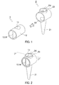
- FIG. 1 is an exploded perspective view of a vessel of Example 1.
- FIG. 2 is a perspective view of the vessel of Example 1.
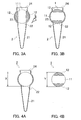
- FIG. 3 is a cross-sectional view of the vessel of Example 1 taken along line I-I of FIG. 2 .
- FIG. 4 (A) is a cross-sectional view of a vessel body and
- FIG. 4 (B) is a cross-sectional view of a cover body.
- identical parts are indicated with identical numerals and symbols.
- a cover body 1 is cylindrical columnar and has a through-hole 11 in a direction perpendicular to an axial direction of the cylindrical column and two sealing positions 12 placed at positions shifted from an opening of the through-hole 11 in a peripheral direction.
- the two sealing positions 12 are opposed to each other in a radial direction of the cover body 1.
- the through-hole 11 is formed so as to be placed at a position corresponding to a side wall opening portion 24 of a cover body containing portion 23 and an upper open-end 22 of a vessel main body 21 in a condition where the cover body 1 is contained in the cover body containing portion 23.
- the shape of the through-hole 11 is not particularly limited.
- the sealing position 12 is a part of an outer peripheral surface of the cover body 1.
- the sealing position 12 is not particularly limited and is applicable as long as it can seal over the upper open-end 22.
- the sealing position 12 may be a part of an outer peripheral surface of the cover body 1, may be formed separately as a thin plate at a part of the outer peripheral surface, or may be formed as convex that fits into the upper open-end 22, for example.
- the shape of the thin plate is not particularly limited, and examples thereof include rectangular, circular, and the like.
- the shape of the convex is not particularly limited, and examples thereof include prismatic column, cylindrical column, sphere, and the like.
- the vessel of the present invention can increase its sealing ability.
- a rotation operating portion 13 is formed at one end of the cover body 1. As shown in FIGs. 1 and 2 , the rotation operating portion 13 is formed by making a hole at the end of the cover body 1 while leaving a linear part.
- the numeral 14 indicates a linear rotation operating portion.
- the shape of the rotation operating portion 13 is not particularly limited.
- the shape of the rotation operating portion 13 examples include a protruding portion and a grooved portion, that have linear shape, cross shape, and the like, and the linear shape is preferable.
- the vessel of the present invention can be opened and closed easily, without detaching and attaching a cover, by rotating the rotation operating portion 13 around the axial direction of the cylindrical columnar cover body by using a rotation portion of an autoanalyzer, for example. Further, in the vessel of the present invention, as described above, the rotation operating portion 13 can be used as the opening and closing recognizing portion.
- an autoanalyzer which uses the vessel of the present invention as an analysis vessel, includes a rotation portion for rotating the rotation operating portion 13, and a state of opening and closing of the vessel of the present invention may be estimated by a rotational angle of the rotation operating portion 13, for example.
- a vessel body 2 includes the vessel main body 21 that is tubular and has an upper open-end and a lower closed-end, and the cover body containing portion 23 that is cylindrical tubular and having at least one open-end.
- the vessel main body 21 and the cover body containing portion 23 are combined by placing the cover body containing portion 23 at the upper open-end 22 of the vessel main body 21 in a condition where an axial direction of the vessel main body 21 is approximately perpendicular to an axial direction of the cover body containing portion 23.
- the axial direction of the vessel main body 21 is approximately perpendicular to the axial direction of the cover body containing portion 23.
- FIG. 5 An example of a vessel body of the vessel of the present invention is shown in FIG. 5 .
- an arrow X indicates the axial direction of the cover body containing portion 23 and an arrow Y indicates the axial direction of the vessel main body 21.
- FIG. 5 (A) is a side view of the vessel body 2 in which the axial direction X of the cover body containing portion 23 is approximately perfectly perpendicular to the axial direction Y of the vessel main body 21.
- FIG. 5 (B) is a side view of the vessel body 2, in which the axial direction X of the cover body containing portion 23 is practically perpendicular to the axial direction Y of the vessel main body 21 although the axial direction Y of the vessel main body 21 is inclined a little.
- identical parts to those shown in FIGs.1 to 4 are indicated with identical numerals and symbols.
- the vessel main body 21 has a shape that tapers downwardly.
- the shape of the vessel main body 21 is tubular, and examples of the tubular include cylindrical tubular, square tubular, and the like.
- the vessel main body 21 may have a shape that tapers downwardly.
- the shape of the cover body containing portion 23 is tubular, and is preferably cylindrical tubular although the tubular is not particularly limited.
- the shape of the upper open-end 22 of the vessel main body 21 is not particularly limited.
- Examples of the shape of the upper open-end 22 of the vessel main body 21 include circular, rectangular, rhombic, elliptical, and the like, and circular is preferable.
- an inside of the vessel main body 21 is communicated with an inside of the cover body containing portion 23 through the upper open-end 22, and a side wall opening portion 24 is formed at a side wall of the cover body containing portion 23 over the upper open-end 22 of the vessel main body 21.
- the side wall opening portion 24 is an opening for introducing and discharging a sample, a reagent, and the like.
- the shape of the side wall opening portion 24 is not particularly limited. Examples of the shape of the side wall opening portion 24 include circular, rectangular, and the like, and circular is preferable.
- X is a length of an inner diameter of the cover body containing portion 23 in a direction perpendicular to the axial direction of the cover body containing portion 23, and Y is a length of an outer diameter of the cover body 1 in a radial direction at the two sealing positions 12.
- the vessel of the present invention is configured such that Y is slightly larger than X.
- the length of Y is, for example, in the range of X ⁇ Y ⁇ 1.5X, and preferably in the range of 1.02X ⁇ Y ⁇ 1.06X.
- the material of the vessel body 2 and the cover body 1 is polypropylene.
- the material of the vessel body 2 and the cover body 1 is not limited to the material of Example 1, and an example thereof includes plastic.
- plastic has a property of flexibility or elasticity, or both properties.
- the plastic having the aforementioned properties include polypropylene, polyethylene, polystyrene, polytetrafluoroethylene, and the like.
- capacity of the vessel main body 21 is 0.5 mL. In the vessel of the present invention, capacity of the vessel main body is not limited to the capacity of Example 1.
- the capacity of the vessel main body 21 is, for example, in the range of 0.0001 mL to 100 mL, preferably in the range of 0.01 mL to 10 mL, and more preferably in the range of 0.1 mL to 2 mL.
- the vessel of Example 1 is used as follows.
- FIG. 3 (A) shows a cover-opened state in which an inside of the vessel main body 21 is communicated with the side wall opening portion 24 through the through-hole 11. From the cover-opened state shown in FIG.
- the cover body 1 is rotated by the rotation operating portion 13 (not shown), one of the sealing positions 12 is moved below the side wall opening portion 24 and the other of the sealing positions 12 is moved above the upper open-end 22 of the vessel main body 21, and thereby the inside of the vessel main body 21 is sealed from the outside. Further, from a sealed state (a cover-closed state) shown in FIG.
- the cover body 1 is rotated by the rotation operating portion 13 (not shown), one end of the through-hole 11 is moved below the side wall opening portion 24 and the other end of the through-hole 11 is moved above the upper open-end 22 of the vessel main body 21, the inside of the vessel main body 21 is communicated with the side wall opening portion 24 through the through-hole 11, and thereby the vessel of Example 1 becomes the cover-opened state (see FIG. 3 (A) ).
- the vessel of the present invention is configured such that Y, which is the length of an outer diameter of the cover body in a radial direction at the two sealing positions, is slightly longer than X, which is the length of an inner diameter of the cover body containing portion in a direction perpendicular to the axial direction of the cover body containing portion. Therefore, in the sealed state, the upper open-end and the side wall opening portion have outward pressure-contact with the two sealing positions. Because of this outward pressure-contact, the vessel of the present invention can obtain higher sealing ability.
- the vessel of Example 1 is provided with the aforementioned structure, configured such that the outer diameter Y is larger than the inner diameter X, and utilizes the property of flexibility or elasticity, or both properties. Thereby, the vessel can be opened and closed easily, and achieves higher sealing ability. Further, since the vessel of Example 1 does not require a sealing member such as packing and the like, the number of components and the manufacturing cost can be reduced. Moreover, since the vessel of Example 1 can be opened and closed only by rotational operation of the rotation operating portion 13, it is applicable to an autoanalyzer.
- FIG. 6 is an exploded perspective view of the vessel of Example 2.
- FIG. 7 is a perspective view of the vessel of Example 2.
- identical parts to those shown in FIGs.1 to 5 are indicated with identical numerals and symbols.
- the vessel of Example 2 in the vessel of Example 2, plural plate-like holding portions 27 are formed in a vertical direction at an outer peripheral surface of the cover body containing portion 23 adjacent to the side wall opening portion 24.
- the structure and the usage pattern of the vessel of Example 2 are similar to those of the vessel of Example 1. Since the vessel of Example 2 includes the holding portions 27, it easily can be held by an analyzer or a human hand, and thereby the vessel easily can be attached to or detached from the analyzer.
- the number of the sealing positions 12 is two. However, in the vessel of the present invention, the number of the sealing positions is not limited to two.
- the shape of the holding portion 27 is not particularly limited, and examples thereof include a plate shape, and the like.
- a heat releasing area of the vessel is increased, and temperature control can be performed precisely in analysis with temperature change such as PCR, and the like.
- FIG. 8 is an exploded perspective view of the vessel of Example 3.
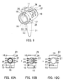
- FIG. 9 is a perspective view of the vessel of Example 3.
- identical parts to those shown in FIGs. 1 to 7 are indicated with identical numerals and symbols.
- a rotation operating ring 15 As shown in FIGs. 8 and 9 , in the vessel of Example 3, a rotation operating ring 15, an opening and closing recognizing portion 16 (an apparatus switch), a stopping portion 17, a latching portion 18, and a support plate 19 further are arranged on the cover body 1.
- the sealing position 12 is formed as a thin plate, and a ribbed surface 25 and a rotation adjusting portion 26 are further arranged on the vessel body 2.
- the structure of the vessel of Example 3 is similar to that of the vessel of Examples 1 and 2.
- the usage pattern of the vessel of Example 3 is similar to that of the vessel of Examples 1 and 2 except for the usage pattern described below.
- the rotation operating ring 15 is formed as the rotation operating portion 13 in addition to the linear rotation operating portion 14.
- the rotation operating ring 15 is provided around the outer peripheral edge of the cover body 1 at one end, and is in contact with one end of the cover body containing portion 23 when the cover body 1 is inserted into the cover body containing portion 23.
- two concaved opening and closing recognizing portions 16 are formed by symmetrically notching a part of the outer peripheral edge.
- the shape of the opening and closing recognizing portion 16 is not particularly limited, and examples thereof include a convex shape, a concave shape, and the like.
- the number of the opening and closing recognizing portions 16 is not particularly limited, and it may be one or more than one.
- the latching portion 18 is formed on the cover body 1 at the other side of the rotation operating ring 15 such that the outer peripheral edge of the cover body 1 is cut at two positions, and an end portion between the insections is outwardly protruded.
- Two latching portions 18 are provided symmetrically at the outer peripheral edge (only one latching portion 18 is shown in FIGs. 8 and 9 ). In a condition where the cover body 1 is contained in the cover body containing portion 23, a protruding portion of the latching portion 18 is latched movably along the outer peripheral edge at one end of the cover body containing portion 23.
- the cover body 1 can be rotated stably without shifting positions of the through-hole 11, the side wall opening portion 24, and the upper open-end 22 in a horizontal direction.
- two stopping portions 17 are symmetrically formed being in contact with the rotation operating ring 15 (only one stopping portion 17 is shown in FIGs. 8 and 9 ).
- a support plate 19 is arranged in the inside of the cover body 1 except for the through-hole 11.
- the number of the sealing positions 12 is two.
- the number of the sealing positions is not limited to two.
- the number of the latching portions 18 and the number of the stopping portions 17 are two.
- the number of the latching portions and the number of the stopping portions are not limited to two.
- the rotation adjusting portion 26 is formed by notching 1/4 of both peripheral edges of the cover body containing portion 23 into strips.
- the number of the rotation adjusting portions is not particularly limited, and it may be one or more than one, for example.
- a slightly raised ribbed surface 25 is formed parallel to the axial direction. In the sealed state, the sealing positions 12 have outward pressure-contact with the ribbed surface 25, and thereby the vessel of Example 3 further can obtain higher sealing ability and strength.
- the ribbed surface is not limited to be formed at the inner peripheral surface of the cover body containing portion adjacent to the upper open-end, and further may be formed at an inner peripheral surface of the cover body containing portion adjacent to the side wall opening portion, for example.
- the vessel of the present invention can obtain higher sealing ability and strength.
- the vessel of Example 3 is used as follows.
- the cover body 1 is inserted rotatably into an inside of the cover body containing portion 23 from one end thereof.
- FIG. 10 is a top view of the vessel in the cover-opened state, in the cover-closed state, and a halfway of a process of opening and closing.
- FIG. 10 (A) is a top view of the vessel when the cover is opened.
- FIG. 10 (B) is a top view of the vessel at the halfway of the process of opening and closing.
- FIG. 10 (C) is a top view of the vessel when the cover is sealed.
- the upper open-end 22 is communicated with the side wall opening portion 24 through the through-hole 11, and the vessel is opened. Further, in FIG.
- the stopping portion 17 is arranged at a left end of the rotation adjusting portion 26, and is movable in rightward direction (clockwise direction viewed from the side of the rotation operating ring 15) in FIG. 10 (A) .
- FIG. 10 (B) by rotating clockwise the linear rotation operating portion 14 (not shown) or the rotation operating ring 15, the through-hole 11 formed on the cover body 1 is rotated clockwise. Because of this rotation, one of the two sealing positions 12 begins to cover the side wall opening portion 24. As shown in FIG.
- the autoanalyzer using the vessel of Example 3 can use the positions of the two opening and closing recognizing portions 16 as a signal for opening and closing of the vessel.
- FIG. 11 shows schematic views of an example of the relationship between the opening and closing recognizing portions 16 of the cover body 1 and the recognizing mechanism of the autoanalyzer.
- FIG. 11 (A) is a schematic view of the vessel in a state where a cover is recognized to be opened.
- FIG. 11 (B) is a schematic view in a state where the cover is recognized to be sealed. In FIGs.
- FIG. 11 (A) and 11 (B) the vessel body 1 is viewed from a rotational axis direction.
- An arrow in a rotational direction in FIG. 11 (A) shows a rotational direction of the cover body 1.
- arrows in the right and left directions in FIGs. 11 (A) and 11 (B) indicate a moving direction of a terminal 41 of the autoanalyzer.
- the terminal 41 of the autoanalyzer is pushed by the cover body 1 and moved rightward in FIG. 11 (A) .
- a leaf spring 43 is pressed and a switch 42 of the autoanalyzer is turned on.
- FIG. 11 (B) when the opening and closing recognizing portions 16 are positioned in the horizontal direction (right and left direction), the terminal 41 of the autoanalyzer is fitted into the concaved opening and closing recognizing portions 16 and is moved leftward in FIG. 11 (B) . Therefore, the leaf spring 43 is released from a compressed state and the switch 42 of the autoanalyzer is turned off.
- the relationship between ON and OFF may be reversed.
- the relationship between the opening and closing recognizing portions 16 and the recognizing mechanism of the autoanalyzer is not limited to this example.
- FIG. 12 is an exploded perspective view of the vessel of Example 4.
- FIG. 13 is a perspective view of the vessel of Example 4.
- FIG. 14 is a perspective view of a cover body 1 of the vessel of Example 4 before attaching an O ring 32.
- FIG. 15 is cross-sectional views of the vessel of Example 4 taken along line II to II of FIG. 13 .
- identical parts to those shown in FIGs.1 to 11 are indicated with identical numerals and symbols.
- an annular groove 31 further is formed at the sealing position 12 of the cover body 1, and an O ring 32 being a circular ring is attached to the annular groove 31.
- the annular groove 31 is formed to be placed at a position surrounding around the upper open-end 22 at the time of sealing.
- the structure of the vessel of Example 4 is similar to that of the vessel of Examples 1 to 3.
- the usage pattern of the vessel of Example 4 is similar to that of the vessel of Examples 1 to 3 except for the usage pattern described below.
- the number of annular grooves 31 is not particularly limited, and it may be one or more than one, for example.
- the material of the O ring 32 is not particularly limited, and examples thereof include nitrile rubber, fluorine-containing rubber, silicone rubber, Teflon (registered trademark), and the like.
- the vessel of Example 4 is used as follows.
- the cover body 1 is rotatably inserted into an inside of the cover body containing portion 23 from one end thereof.
- FIG. 15 (A) is a cross-sectional view of the vessel of Example 4 in the cover-opened state.
- FIG. 15 (B) is a cross-sectional view of the vessel of Example 4 in the cover-sealed state.
- the upper open-end 22 is communicated with the side wall opening portion 24 through the through-hole 11, and the vessel is opened.
- FIG. 13 (B) by rotating clockwise the rotation operating portion 13 (not shown), the sealing position 12 formed on the cover body 1 is rotated clockwise. Because of this rotation, the sealing position 12 at which the annular groove 31 is formed is moved above the upper open-end 22, and the O ring 32 attached to the annular groove 31 is closely in contact with an inner peripheral surface of the cover body containing portion 23. Thereby the vessel of Example 4 is sealed (see FIG. 15 (B) ).
- the vessel of Example 4 can obtain higher sealing ability.
- the vessel of Example 4 is provided with the aforementioned structure in addition to the structure of Example 3, the vessel can increase the sealing ability.
- the vessel of the present invention When the vessel of the present invention is used, the vessel can easily be opened and closed without detaching and attaching the cover. Therefore, the vessel of the present invention is easily applicable to an autoanalyzer.
- the vessel of the present invention is also excellent in sealing ability. Therefore, the intended use of the vessel of the present invention is not limited and it can be applied suitably to a broad range of technical fields such as genetic engineering, biochemistry, physics and chemistry, medical science, and the like.
Landscapes
- Engineering & Computer Science (AREA)
- General Engineering & Computer Science (AREA)
- Health & Medical Sciences (AREA)
- Chemical & Material Sciences (AREA)
- Mechanical Engineering (AREA)
- General Health & Medical Sciences (AREA)
- Analytical Chemistry (AREA)
- Clinical Laboratory Science (AREA)
- Life Sciences & Earth Sciences (AREA)
- Chemical Kinetics & Catalysis (AREA)
- Hematology (AREA)
- Public Health (AREA)
- Immunology (AREA)
- Veterinary Medicine (AREA)
- General Physics & Mathematics (AREA)
- Biochemistry (AREA)
- Animal Behavior & Ethology (AREA)
- Pharmacology & Pharmacy (AREA)
- Physics & Mathematics (AREA)
- Pathology (AREA)
- Automatic Analysis And Handling Materials Therefor (AREA)
- Closures For Containers (AREA)
- Sampling And Sample Adjustment (AREA)
- Apparatus Associated With Microorganisms And Enzymes (AREA)
Abstract
Description
- The present invention relates to a vessel and an analysis vessel using the same.
- Conventionally, in an analysis using a physical and chemical analysis apparatus, a medical analysis apparatus, and the like, a vessel that stores an object to be analyzed has been used. In order to prevent deterioration in the analysis accuracy due to evaporation and dispersion of a sample in a vessel during an analysis, the vessel is required to be sealed in an air-tight and liquid-tight manner. Therefore, in conventionally used vessels, for example, a screw cap structure and a fit-in structure (for example, Patent Document 1) are used. The screw cap structure is provided with a packing and the fit-in structure uses flexibility of resin. Accordingly, conventional vessels require operations of removing a cover, moving the thus removed cover elsewhere, reattaching the removed cover, and the like at the time of opening and closing the vessels.
- In contrast, in a field of the physical and chemical analysis, the medical analysis, and the like, the development of an autoanalyzer in which the whole series of measurement operation is automated is desired. However, in a case where a conventional vessel is used, an autoanalyzer requires a mechanism for operating an opening and closing of the vessel. In addition, it requires operation accuracy such as positioning at the time of fitting a cover into a vessel body. Therefore, with respect to the autoanalyzer, the number of apparatus mechanisms is increased, the apparatus thus is complicated, and the size of the apparatus itself is also increased.
- Patent Document 1:
JP4(1992)-31945 - Hence, the present invention is intended to provide a vessel easily capable of being opened and closed without detaching and attaching a cover and easily applicable to an autoanalyzer.
- In order to achieve the aforementioned object, the vessel of the present invention is a vessel that includes:
- a vessel body; and
- a cover body, wherein
- the vessel body includes:
- a vessel main body being tubular and having an upper open-end and a lower closed-end; and
- a cover body containing portion being tubular and having at least one open-end,
- the cover body containing portion is placed at the upper open-end of the vessel main body and the vessel main body and the cover body containing portion are combined in a condition where an axial direction of the vessel main body is approximately perpendicular to an axial direction of the cover body containing portion,
- an inside of the vessel main body is communicated with an inside of the cover body containing portion through the upper open-end,
- an opening portion is formed at a side wall of the cover body containing portion over the upper open-end of the vessel main body,
- the cover body is columnar and has a through-hole in a direction perpendicular to an axial direction of the column, and a sealing position at a position shifted from an opening of the through-hole in a peripheral direction, the cover body is coaxially and rotatably containable in an inside of the cover body containing portion in a condition where an outer peripheral surface of the cover body is in contact with an inner peripheral surface of the cover body containing portion,
- the through-hole of the cover body is formed so as to be placed at a position corresponding to the side wall opening portion of the cover body containing portion and the upper open-end of the vessel main body in a condition where the cover body is contained in the cover body containing portion,
- in a condition where the cover body is contained in the cover body containing portion, when the cover body is rotated and one end of the through-hole is placed below the side wall opening portion and the other end of the through-hole is placed above the upper open-end of the vessel main body, the inside of the vessel main body is communicated with the side wall opening portion through the through-hole, and
- when the cover body is rotated and the sealing position is placed over the upper open-end of the vessel main body, the inside of the vessel main body is sealed from the outside.
- Since the vessel of the present invention can perform opening and closing by rotating a cover body, the vessel can be opened and closed easily without detaching and attaching a cover. Therefore, the vessel is easily applicable to an autoanalyzer and is excellent in sealing ability. Further, when the vessel of the present invention is applied to an autoanalyzer, the vessel requires neither a means for moving a cover nor a high positioning accuracy. Therefore, opening and closing of the vessel can be performed with a simple mechanism.
-
- [
FIG. 1] FIG. 1 is an exploded perspective view of a cover body and a vessel body in an example of a vessel of the present invention. - [
FIG. 2] FIG. 2 is a perspective view of an example of the vessel of the present invention. - [
FIG. 3] FIG. 3 (A) is a cross-sectional view of an example of the vessel of the present invention in a cover-opened state.FIG. 3 (B) is a cross-sectional view of an example of the vessel of the present invention in a cover-sealed state. - [
FIG. 4] FIG. 4 (A) is a cross-sectional view of a vessel body in an example of the vessel of the present invention.FIG. 4 (B) is a cross-sectional view of a cover body in an example of the vessel of the present invention. - [
FIG. 5] FIG. 5 (A) is a side view of an example of the vessel body.FIG. 5 (B) is a side view of another example of the vessel body. - [
FIG. 6] FIG. 6 is an exploded perspective view of a cover body and a vessel body in another example of a vessel of the present invention. - [
FIG. 7] FIG. 7 is a perspective view of another example of the vessel of the present invention. - [
FIG. 8] FIG. 8 is an exploded perspective view of a cover body and a vessel body in yet another example of a vessel of the present invention. - [
FIG. 9] FIG. 9 is a perspective view of yet another example of the vessel of the present invention. - [
FIG. 10] FIG. 10 is a top view of a vessel showing a process of opening and closing in yet another example of the vessel of the present invention.FIG. 10 (A) is a top view of the vessel in a cover-opened state.FIG. 10 (B) is a top view of the vessel in a state of transferring from a cover-opened state to a cover-sealed state.FIG. 10 (C) is a top view of the vessel in a cover-sealed state. - [
FIG. 11] FIG. 11 is a schematic view showing a relationship between an opening and closing recognizing portion of a cover body and a recognizing mechanism of an autoanalyzer in yet another example of the vessel of the present invention.FIG 11 (A) is a schematic view in a state where a cover is recognized to be opened.FIG. 11 (B) is a schematic view in a state where the cover is recognized to be sealed. - [
FIG. 12] FIG. 12 is an exploded perspective view of a cover body and a vessel body in yet another example of a vessel of the present invention. - [
FIG. 13] FIG. 13 is a perspective view of yet another example of the vessel of the present invention. - [
FIG. 14] FIG. 14 is an exploded perspective view of a cover body and an O ring to be attached in yet another example of the vessel of the present invention. - [
FIG. 15] FIG. 15 (A) is a cross-sectional view of yet another example of the vessel of the present invention in a cover-opened state.FIG. 15 (B) is a cross-sectional view of yet another example of the vessel of the present invention in a cover-sealed state. - Preferably, in the vessel (container) of the present invention, the cover body containing portion is cylindrical tubular and the cover body is cylindrical columnar, two sealing positions are placed at positions opposed to each other in a radial direction of the cover body in the cover body, and an inner diameter X of the cover body containing portion in a direction perpendicular to an axial direction of the cover body containing portion and an outer diameter Y of the cover body in a radial direction at the two sealing positions satisfy a relationship of Y > X. More preferably, the inner diameter X and the outer diameter Y satisfy a relationship of X < Y < 1.5. When the relationship of X<Y<1.5 is satisfied, in the vessel of the present invention, the cover body has outward pressure-contact with the cover body containing portion at the sealing positions, rotation of the cover body is facilitated, and good sealing ability and operability can be achieved.
- In the vessel of the present invention, the number of the sealing positions is preferably two although it is not particularly limited. Further, in the vessel of the present invention, the shape of the sealing position is preferably a convex, which fits into the upper open-end, or a thin plate.
- Preferably, the vessel has a ribbed surface at an inner peripheral surface of the cover body containing portion adjacent to the upper open-end.
- Preferably, in the vessel of the present invention, a rotation operating portion for rotationally operating the cover body is formed at at least one end of the cover body. Preferably, in the vessel of the present invention, the rotation operating portion is formed linearly.
- In the vessel of the present invention, a holding portion may be formed at an outer peripheral surface of the cover body containing portion.
- In the vessel of the present invention, a rotation adjusting portion, which is made by notching a part of a peripheral edge into strips, may be formed at at least one end of the cover body containing portion, a stopping portion may be formed on an outer peripheral surface at at least one end of the cover body, and the stopping portion may be rotationally movable only within the rotation adjusting portion during a rotational operation of the cover body.
- In the vessel of the present invention, a latching portion may be formed at a part of an outer peripheral edge at one end of the cover body.
- Preferably, in the vessel of the present invention, an opening and closing recognizing portion is formed at at least one end of the cover body. When such opening and closing recognizing portion is formed, for example, an autoanalyzer can recognize opening and closing of the vessel.
- Preferably, in the vessel of the present invention, the vessel body and the cover body are made of plastic.
- The analysis vessel of the present invention uses the vessel of the present invention. The analysis vessel of the present invention may be an analysis vessel for use in a gene analysis, for example. The gene analysis is not particularly limited, and examples thereof include PCR reaction and the like.
- The present invention is explained with Examples. However, the present invention is not limited by the following Examples.
- An example of a vessel of the present invention is shown in
FIGs. 1 to 4 .FIG. 1 is an exploded perspective view of a vessel of Example 1.FIG. 2 is a perspective view of the vessel of Example 1.FIG. 3 is a cross-sectional view of the vessel of Example 1 taken along line I-I ofFIG. 2 .FIG. 4 (A) is a cross-sectional view of a vessel body andFIG. 4 (B) is a cross-sectional view of a cover body. InFIGs. 1 to 4 , identical parts are indicated with identical numerals and symbols. - As shown in
FIGs. 1 to 4 , acover body 1 is cylindrical columnar and has a through-hole 11 in a direction perpendicular to an axial direction of the cylindrical column and two sealingpositions 12 placed at positions shifted from an opening of the through-hole 11 in a peripheral direction. The two sealingpositions 12 are opposed to each other in a radial direction of thecover body 1. The through-hole 11 is formed so as to be placed at a position corresponding to a sidewall opening portion 24 of a coverbody containing portion 23 and an upper open-end 22 of a vesselmain body 21 in a condition where thecover body 1 is contained in the coverbody containing portion 23. In the vessel of the present invention, the shape of the through-hole 11 is not particularly limited. Examples of the shape of the through-hole 11 include cylindrical tubular, square tubular, and the like, and cylindrical tubular is preferable. In the vessel of Example 1, the sealingposition 12 is a part of an outer peripheral surface of thecover body 1. However, in the vessel of the present invention, the sealingposition 12 is not particularly limited and is applicable as long as it can seal over the upper open-end 22. In the vessel of the present invention, the sealingposition 12 may be a part of an outer peripheral surface of thecover body 1, may be formed separately as a thin plate at a part of the outer peripheral surface, or may be formed as convex that fits into the upper open-end 22, for example. The shape of the thin plate is not particularly limited, and examples thereof include rectangular, circular, and the like. The shape of the convex is not particularly limited, and examples thereof include prismatic column, cylindrical column, sphere, and the like. When the sealing position is formed as the thin plate, the convex, or the like, the vessel of the present invention can increase its sealing ability. Further, in the vessel of Example 1, arotation operating portion 13 is formed at one end of thecover body 1. As shown inFIGs. 1 and 2 , therotation operating portion 13 is formed by making a hole at the end of thecover body 1 while leaving a linear part. InFIGs. 1 and 2 , the numeral 14 indicates a linear rotation operating portion. In the vessel of the present invention, the shape of therotation operating portion 13 is not particularly limited. Examples the shape of therotation operating portion 13 include a protruding portion and a grooved portion, that have linear shape, cross shape, and the like, and the linear shape is preferable. The vessel of the present invention can be opened and closed easily, without detaching and attaching a cover, by rotating therotation operating portion 13 around the axial direction of the cylindrical columnar cover body by using a rotation portion of an autoanalyzer, for example. Further, in the vessel of the present invention, as described above, therotation operating portion 13 can be used as the opening and closing recognizing portion. In this case, an autoanalyzer, which uses the vessel of the present invention as an analysis vessel, includes a rotation portion for rotating therotation operating portion 13, and a state of opening and closing of the vessel of the present invention may be estimated by a rotational angle of therotation operating portion 13, for example. - As shown in
FIGs. 1 to 4 , avessel body 2 includes the vesselmain body 21 that is tubular and has an upper open-end and a lower closed-end, and the coverbody containing portion 23 that is cylindrical tubular and having at least one open-end. The vesselmain body 21 and the coverbody containing portion 23 are combined by placing the coverbody containing portion 23 at the upper open-end 22 of the vesselmain body 21 in a condition where an axial direction of the vesselmain body 21 is approximately perpendicular to an axial direction of the coverbody containing portion 23. In the vessel of the present invention, the axial direction of the vesselmain body 21 is approximately perpendicular to the axial direction of the coverbody containing portion 23. It is applicable as long as the axial direction of the vesselmain body 21 is practically perpendicular to the axial direction of the coverbody containing portion 23, and the axial direction of the vesselmain body 21 perfectly may be perpendicular or may not be perfectly perpendicular to the axial direction of the coverbody containing portion 23. An example of a vessel body of the vessel of the present invention is shown inFIG. 5 . InFIG. 5 , an arrow X indicates the axial direction of the coverbody containing portion 23 and an arrow Y indicates the axial direction of the vesselmain body 21.FIG. 5 (A) is a side view of thevessel body 2 in which the axial direction X of the coverbody containing portion 23 is approximately perfectly perpendicular to the axial direction Y of the vesselmain body 21.FIG. 5 (B) is a side view of thevessel body 2, in which the axial direction X of the coverbody containing portion 23 is practically perpendicular to the axial direction Y of the vesselmain body 21 although the axial direction Y of the vesselmain body 21 is inclined a little. InFIGs. 5 (A) and 5 (B) , identical parts to those shown inFIGs.1 to 4 are indicated with identical numerals and symbols. - As shown in
FIGs. 1 to 4 , in the vessel of Example 1, the vesselmain body 21 has a shape that tapers downwardly. In the vessel of the present invention, as described above, the shape of the vesselmain body 21 is tubular, and examples of the tubular include cylindrical tubular, square tubular, and the like. For example, the vesselmain body 21 may have a shape that tapers downwardly. In the vessel of the present invention, the shape of the coverbody containing portion 23 is tubular, and is preferably cylindrical tubular although the tubular is not particularly limited. Further, in the vessel of the present invention, the shape of the upper open-end 22 of the vesselmain body 21 is not particularly limited. Examples of the shape of the upper open-end 22 of the vesselmain body 21 include circular, rectangular, rhombic, elliptical, and the like, and circular is preferable. In thevessel body 2, an inside of the vesselmain body 21 is communicated with an inside of the coverbody containing portion 23 through the upper open-end 22, and a sidewall opening portion 24 is formed at a side wall of the coverbody containing portion 23 over the upper open-end 22 of the vesselmain body 21. For example, the sidewall opening portion 24 is an opening for introducing and discharging a sample, a reagent, and the like. In the vessel of the present invention, the shape of the sidewall opening portion 24 is not particularly limited. Examples of the shape of the sidewall opening portion 24 include circular, rectangular, and the like, and circular is preferable. - As shown in
FIGs. 4 (A) and 4 (B) , X is a length of an inner diameter of the coverbody containing portion 23 in a direction perpendicular to the axial direction of the coverbody containing portion 23, and Y is a length of an outer diameter of thecover body 1 in a radial direction at the two sealing positions 12. In the vessel of Example 1, X and Y satisfy the relationship of Y = X × 1.04. As described above, the vessel of the present invention is configured such that Y is slightly larger than X. In the vessel of the present invention, the length of Y is, for example, in the range of X<Y<1.5X, and preferably in the range of 1.02X < Y < 1.06X. - In Example 1, the material of the
vessel body 2 and thecover body 1 is polypropylene. In the present invention, the material of thevessel body 2 and thecover body 1 is not limited to the material of Example 1, and an example thereof includes plastic. Preferably, plastic has a property of flexibility or elasticity, or both properties. Examples of the plastic having the aforementioned properties include polypropylene, polyethylene, polystyrene, polytetrafluoroethylene, and the like. By using the plastic having the aforementioned properties, the vessel of the present invention can obtain higher sealing ability. - In the vessel of Example 1, capacity of the vessel
main body 21 is 0.5 mL. In the vessel of the present invention, capacity of the vessel main body is not limited to the capacity of Example 1. The capacity of the vesselmain body 21 is, for example, in the range of 0.0001 mL to 100 mL, preferably in the range of 0.01 mL to 10 mL, and more preferably in the range of 0.1 mL to 2 mL. - For example, the vessel of Example 1 is used as follows.
- As shown in
FIGs. 1 to 4 , in the vessel of Example 1, thecover body 1 is coaxially and rotatably inserted into an inside of the coverbody containing portion 23 from an opening at one end thereof in a condition where an outer peripheral surface of thecover body 1 is in contact with an inner peripheral surface of the coverbody containing portion 23.FIG. 3 (A) shows a cover-opened state in which an inside of the vesselmain body 21 is communicated with the sidewall opening portion 24 through the through-hole 11. From the cover-opened state shown inFIG. 3 (A) , thecover body 1 is rotated by the rotation operating portion 13 (not shown), one of the sealing positions 12 is moved below the sidewall opening portion 24 and the other of the sealing positions 12 is moved above the upper open-end 22 of the vesselmain body 21, and thereby the inside of the vesselmain body 21 is sealed from the outside. Further, from a sealed state (a cover-closed state) shown inFIG. 3 (B) , thecover body 1 is rotated by the rotation operating portion 13 (not shown), one end of the through-hole 11 is moved below the sidewall opening portion 24 and the other end of the through-hole 11 is moved above the upper open-end 22 of the vesselmain body 21, the inside of the vesselmain body 21 is communicated with the sidewall opening portion 24 through the through-hole 11, and thereby the vessel of Example 1 becomes the cover-opened state (seeFIG. 3 (A) ). As described above, the vessel of the present invention is configured such that Y, which is the length of an outer diameter of the cover body in a radial direction at the two sealing positions, is slightly longer than X, which is the length of an inner diameter of the cover body containing portion in a direction perpendicular to the axial direction of the cover body containing portion. Therefore, in the sealed state, the upper open-end and the side wall opening portion have outward pressure-contact with the two sealing positions. Because of this outward pressure-contact, the vessel of the present invention can obtain higher sealing ability. - In this manner, the vessel of Example 1 is provided with the aforementioned structure, configured such that the outer diameter Y is larger than the inner diameter X, and utilizes the property of flexibility or elasticity, or both properties. Thereby, the vessel can be opened and closed easily, and achieves higher sealing ability. Further, since the vessel of Example 1 does not require a sealing member such as packing and the like, the number of components and the manufacturing cost can be reduced. Moreover, since the vessel of Example 1 can be opened and closed only by rotational operation of the
rotation operating portion 13, it is applicable to an autoanalyzer. - Another example of a vessel of the present invention is shown in
FIGs. 6 and7 .FIG. 6 is an exploded perspective view of the vessel of Example 2.FIG. 7 is a perspective view of the vessel of Example 2. InFIGs. 6 and7 , identical parts to those shown inFIGs.1 to 5 are indicated with identical numerals and symbols. - As shown in
FIGs. 6 and7 , in the vessel of Example 2, plural plate-like holding portions 27 are formed in a vertical direction at an outer peripheral surface of the coverbody containing portion 23 adjacent to the sidewall opening portion 24. Other than these, the structure and the usage pattern of the vessel of Example 2 are similar to those of the vessel of Example 1. Since the vessel of Example 2 includes the holdingportions 27, it easily can be held by an analyzer or a human hand, and thereby the vessel easily can be attached to or detached from the analyzer. In the vessel of Example 2, in the same manner as in Example 1, the number of the sealing positions 12 is two. However, in the vessel of the present invention, the number of the sealing positions is not limited to two. - In the vessel of the present invention, the shape of the holding
portion 27 is not particularly limited, and examples thereof include a plate shape, and the like. As in Example 2, when the plate-like holding portion 27 is used, a heat releasing area of the vessel is increased, and temperature control can be performed precisely in analysis with temperature change such as PCR, and the like. - Another example of a vessel of the present invention is shown in
FIGs. 8 and9 .FIG. 8 is an exploded perspective view of the vessel of Example 3.FIG. 9 is a perspective view of the vessel of Example 3. InFIGs. 8 and9 , identical parts to those shown inFIGs. 1 to 7 are indicated with identical numerals and symbols. - As shown in
FIGs. 8 and9 , in the vessel of Example 3, arotation operating ring 15, an opening and closing recognizing portion 16 (an apparatus switch), a stoppingportion 17, a latchingportion 18, and asupport plate 19 further are arranged on thecover body 1. The sealingposition 12 is formed as a thin plate, and aribbed surface 25 and arotation adjusting portion 26 are further arranged on thevessel body 2. Other than these, the structure of the vessel of Example 3 is similar to that of the vessel of Examples 1 and 2. Further, the usage pattern of the vessel of Example 3 is similar to that of the vessel of Examples 1 and 2 except for the usage pattern described below. - In the
cover body 1 of Example 3, therotation operating ring 15 is formed as therotation operating portion 13 in addition to the linearrotation operating portion 14. Therotation operating ring 15 is provided around the outer peripheral edge of thecover body 1 at one end, and is in contact with one end of the coverbody containing portion 23 when thecover body 1 is inserted into the coverbody containing portion 23. Further, with respect to therotation operating ring 15, two concaved opening andclosing recognizing portions 16 are formed by symmetrically notching a part of the outer peripheral edge. In the vessel of the present invention, the shape of the opening andclosing recognizing portion 16 is not particularly limited, and examples thereof include a convex shape, a concave shape, and the like. Further, the number of the opening andclosing recognizing portions 16 is not particularly limited, and it may be one or more than one. In the vessel of Example 3, the latchingportion 18 is formed on thecover body 1 at the other side of therotation operating ring 15 such that the outer peripheral edge of thecover body 1 is cut at two positions, and an end portion between the insections is outwardly protruded. Two latchingportions 18 are provided symmetrically at the outer peripheral edge (only one latchingportion 18 is shown inFIGs. 8 and9 ). In a condition where thecover body 1 is contained in the coverbody containing portion 23, a protruding portion of the latchingportion 18 is latched movably along the outer peripheral edge at one end of the coverbody containing portion 23. Thereby, thecover body 1 can be rotated stably without shifting positions of the through-hole 11, the sidewall opening portion 24, and the upper open-end 22 in a horizontal direction. Further, on the outer peripheral surface of thecover body 1 at one end, two stoppingportions 17 are symmetrically formed being in contact with the rotation operating ring 15 (only one stoppingportion 17 is shown inFIGs. 8 and9 ). Moreover, in the inside of thecover body 1 except for the through-hole 11, in order to increase physical strength of thecover body 1, asupport plate 19 is arranged. In the vessel of Example 3, as in Examples 1 and 2, the number of the sealing positions 12 is two. However, in the vessel of the present invention, the number of the sealing positions is not limited to two. Further, in the vessel of Example 3, the number of the latchingportions 18 and the number of the stoppingportions 17 are two. However, in the vessel of the present invention, the number of the latching portions and the number of the stopping portions are not limited to two. - In the
vessel body 2 of Example 3, tworotation adjusting portions 26 are formed. Therotation adjusting portion 26 is formed by notching 1/4 of both peripheral edges of the coverbody containing portion 23 into strips. In the vessel of the present invention, the number of the rotation adjusting portions is not particularly limited, and it may be one or more than one, for example. Further, in thevessel body 2 of Example 3, at an inner peripheral surface of the coverbody containing portion 23 adjacent to the upper open-end 22, a slightly raised ribbedsurface 25 is formed parallel to the axial direction. In the sealed state, the sealingpositions 12 have outward pressure-contact with theribbed surface 25, and thereby the vessel of Example 3 further can obtain higher sealing ability and strength. In the vessel of the present invention, the ribbed surface is not limited to be formed at the inner peripheral surface of the cover body containing portion adjacent to the upper open-end, and further may be formed at an inner peripheral surface of the cover body containing portion adjacent to the side wall opening portion, for example. When the ribbed surface also is formed at the side of the side wall opening portion, the vessel of the present invention can obtain higher sealing ability and strength. - For example, the vessel of Example 3 is used as follows.
- As shown in
FIGs. 8 and9 , thecover body 1 is inserted rotatably into an inside of the coverbody containing portion 23 from one end thereof. -
FIG. 10 is a top view of the vessel in the cover-opened state, in the cover-closed state, and a halfway of a process of opening and closing.FIG. 10 (A) is a top view of the vessel when the cover is opened.FIG. 10 (B) is a top view of the vessel at the halfway of the process of opening and closing.FIG. 10 (C) is a top view of the vessel when the cover is sealed. InFIG. 10 (A) , the upper open-end 22 is communicated with the sidewall opening portion 24 through the through-hole 11, and the vessel is opened. Further, inFIG. 10 (A) , the stoppingportion 17 is arranged at a left end of therotation adjusting portion 26, and is movable in rightward direction (clockwise direction viewed from the side of the rotation operating ring 15) inFIG. 10 (A) . As shown inFIG. 10 (B) , by rotating clockwise the linear rotation operating portion 14 (not shown) or therotation operating ring 15, the through-hole 11 formed on thecover body 1 is rotated clockwise. Because of this rotation, one of the two sealingpositions 12 begins to cover the sidewall opening portion 24. As shown inFIG. 10 (C) , when thecover body 1 is rotated 90 degrees (1/4 of the whole circumference of the cover body 1), the two sealingpositions 12 respectively seal the upper open-end 22 (not shown) and the sidewall opening portion 24 at the same time, and thereby the vessel is sealed. When the vessel is sealed, the stoppingportion 17 reaches a right end of therotation adjusting portion 26. Therefore, thecover body 1 does not further rotate clockwise. In this manner, in the vessel of Example 3, by providing therotation adjusting portion 26 and the stoppingportion 17 as described above, a rotational operation is limited to 90 degrees, and switching between the complete cover-opened state and the complete cover-sealed state can be easily performed. Therefore, an autoanalyzer using the vessel of Example 3 can automatically open and close the vessel only by providing with a mechanism for rotatably operating the linearrotation operating portion 14 as a vessel opening and closing mechanism. - In the vessel of Example 3, when the two opening and
closing recognizing portions 16 are positioned in a vertical direction (an up-and-down direction), it is referred to as a cover-opened state, and when the two opening andclosing recognizing portions 16 are positioned in a horizontal direction (right and left direction), it is referred to as a cover-sealed state. That is, the autoanalyzer using the vessel of Example 3 can use the positions of the two opening andclosing recognizing portions 16 as a signal for opening and closing of the vessel. Therefore, when the autoanalyzer is provided with a mechanism for recognizing positions of the concaved opening andclosing recognizing portions 16 and a mechanism for estimating the opened and closed state of the vessel from the aforementioned positions, the autoanalyzer can recognize the opened and closed state of the vessel.FIG. 11 shows schematic views of an example of the relationship between the opening andclosing recognizing portions 16 of thecover body 1 and the recognizing mechanism of the autoanalyzer.FIG. 11 (A) is a schematic view of the vessel in a state where a cover is recognized to be opened.FIG. 11 (B) is a schematic view in a state where the cover is recognized to be sealed. InFIGs. 11 (A) and 11 (B) , thevessel body 1 is viewed from a rotational axis direction. An arrow in a rotational direction inFIG. 11 (A) shows a rotational direction of thecover body 1. Further, arrows in the right and left directions inFIGs. 11 (A) and 11 (B) indicate a moving direction of a terminal 41 of the autoanalyzer. In the vessel of Example 3, as shown inFIG. 11 (A) , when the opening andclosing recognizing portions 16 are positioned in the vertical direction (up-and-down direction), theterminal 41 of the autoanalyzer is pushed by thecover body 1 and moved rightward inFIG. 11 (A) . Therefore, aleaf spring 43 is pressed and aswitch 42 of the autoanalyzer is turned on. Further, as shown inFIG. 11 (B) , when the opening andclosing recognizing portions 16 are positioned in the horizontal direction (right and left direction), theterminal 41 of the autoanalyzer is fitted into the concaved opening andclosing recognizing portions 16 and is moved leftward inFIG. 11 (B) . Therefore, theleaf spring 43 is released from a compressed state and theswitch 42 of the autoanalyzer is turned off. The relationship between ON and OFF may be reversed. In the vessel of the present invention, the relationship between the opening andclosing recognizing portions 16 and the recognizing mechanism of the autoanalyzer is not limited to this example. - Another example of the vessel of the present invention is shown in
FIGs. 12 to 15 .FIG. 12 is an exploded perspective view of the vessel of Example 4.FIG. 13 is a perspective view of the vessel of Example 4.FIG. 14 is a perspective view of acover body 1 of the vessel of Example 4 before attaching anO ring 32.FIG. 15 is cross-sectional views of the vessel of Example 4 taken along line II to II ofFIG. 13 . InFIGs. 12 to 15 , identical parts to those shown inFIGs.1 to 11 are indicated with identical numerals and symbols. - As shown in
FIGs. 12 to 15 , in the vessel of Example 4, anannular groove 31 further is formed at the sealingposition 12 of thecover body 1, and anO ring 32 being a circular ring is attached to theannular groove 31. Theannular groove 31 is formed to be placed at a position surrounding around the upper open-end 22 at the time of sealing. Other than these, the structure of the vessel of Example 4 is similar to that of the vessel of Examples 1 to 3. Further, the usage pattern of the vessel of Example 4 is similar to that of the vessel of Examples 1 to 3 except for the usage pattern described below. In the vessel of the present invention, the number ofannular grooves 31 is not particularly limited, and it may be one or more than one, for example. In the vessel of the present invention, the material of theO ring 32 is not particularly limited, and examples thereof include nitrile rubber, fluorine-containing rubber, silicone rubber, Teflon (registered trademark), and the like. - For example, the vessel of Example 4 is used as follows.
- As shown in
FIGs. 13 and14 , thecover body 1 is rotatably inserted into an inside of the coverbody containing portion 23 from one end thereof. -
FIG. 15 (A) is a cross-sectional view of the vessel of Example 4 in the cover-opened state.FIG. 15 (B) is a cross-sectional view of the vessel of Example 4 in the cover-sealed state. InFIG. 15 (A) , the upper open-end 22 is communicated with the sidewall opening portion 24 through the through-hole 11, and the vessel is opened. As shown inFIG. 13 (B) , by rotating clockwise the rotation operating portion 13 (not shown), the sealingposition 12 formed on thecover body 1 is rotated clockwise. Because of this rotation, the sealingposition 12 at which theannular groove 31 is formed is moved above the upper open-end 22, and theO ring 32 attached to theannular groove 31 is closely in contact with an inner peripheral surface of the coverbody containing portion 23. Thereby the vessel of Example 4 is sealed (seeFIG. 15 (B) ). In the cover-sealed state, when theO ring 32 is closely in contact with the inner peripheral surface of the coverbody containing portion 23, the vessel of Example 4 can obtain higher sealing ability. - As described above, since the vessel of Example 4 is provided with the aforementioned structure in addition to the structure of Example 3, the vessel can increase the sealing ability.
- When the vessel of the present invention is used, the vessel can easily be opened and closed without detaching and attaching the cover. Therefore, the vessel of the present invention is easily applicable to an autoanalyzer. The vessel of the present invention is also excellent in sealing ability. Therefore, the intended use of the vessel of the present invention is not limited and it can be applied suitably to a broad range of technical fields such as genetic engineering, biochemistry, physics and chemistry, medical science, and the like.
Claims (15)
- A vessel comprising:a vessel body; anda cover body, wherein
the vessel body comprises:a vessel main body being tubular and having an upper open-end and a lower closed-end; anda cover body containing portion being tubular and having at least one open-end,the cover body containing portion is placed at the upper open-end of the vessel main body and the vessel main body and the cover body containing portion are combined in a condition where an axial direction of the vessel main body is approximately perpendicular to an axial direction of the cover body containing portion,an inside of the vessel main body is communicated with an inside of the cover body containing portion through the upper open-end,an opening portion is formed at a side wall of the cover body containing portion over the upper open-end of the vessel main body,the cover body is columnar and has a through-hole in a direction perpendicular to an axial direction of the column, and a sealing position at a position shifted from an opening of the through-hole in a peripheral direction,the cover body is coaxially and rotatably containable in an inside of the cover body containing portion in a condition where an outer peripheral surface of the cover body is in contact with an inner peripheral surface of the cover body containing portion,the through-hole of the cover body is formed so as to be placed at a position corresponding to the side wall opening portion of the cover body containing portion and the upper open-end of the vessel main body in a condition where the cover body is contained in the cover body containing portion,in a condition where the cover body is contained in the cover body containing portion, when the cover body is rotated and one end of the through-hole is placed below the side wall opening portion and the other end of the through-hole is placed above the upper open-end of the vessel main body, the inside of the vessel main body is communicated with the side wall opening portion through the through-hole, andwhen the cover body is rotated and the sealing position is placed over the upper open-end of the vessel main body, the inside of the vessel main body is sealed from the outside. - The vessel according to claim 1, wherein the cover body containing portion is cylindrical tubular and the cover body is cylindrical columnar, in the cover body, two sealing positions are placed at positions opposed to each other in a radial direction of the cover body, and
an inner diameter X of the cover body containing portion in a direction perpendicular to an axial direction of the cover body containing portion and an outer diameter Y of the cover body in a radial direction at the two sealing positions satisfy a relationship ofY > X. - The vessel according to claim 1, wherein the sealing position is a shape of a convex, which fits into the upper open-end, or a shape of a thin plate.
- The vessel according to claim 1, wherein the vessel comprises a ribbed surface at an inner peripheral surface of the cover body containing portion adjacent to the upper open-end.
- The vessel according to claim 2, wherein the inner diameter X of the cover body containing portion and the outer diameter Y of the cover body in a radial direction at the two sealing positions satisfy a relationship of X < Y < 1.5X.
- The vessel according to claim 1, wherein a rotation operating portion for rotationally operating the cover body is formed at at least one end of the cover body.
- The vessel according to claim 6, wherein the rotation operating portion is formed linearly.
- The vessel according to claim 1, wherein a holding portion is formed at an outer peripheral surface of the cover body containing portion.
- The vessel according to claim 1, wherein a rotation adjusting portion, which is made by notching a part of a peripheral edge into strips, is formed at at least one end of the cover body containing portion, a stopping portion is formed on an outer peripheral surface at at least one end of the cover body, and the stopping portion is rotationally movable only within the rotation adjusting portion during a rotational operation of the cover body.
- The vessel according to claim 1, wherein a latching portion is formed at a part of an outer peripheral edge at one end of the cover body.
- The vessel according to claim 1, wherein an opening and closing recognizing portion is formed at at least one end of the cover body.
- The vessel according to claim 1, wherein the vessel body and the cover body are made of plastic.
- An analysis vessel for use in an analysis, wherein the vessel is the vessel according to claim 1.
- The analysis vessel according to claim 13, wherein the analysis is a gene analysis.
- The analysis vessel according to claim 14, wherein the gene analysis is an analysis by PCR.
Applications Claiming Priority (2)
| Application Number | Priority Date | Filing Date | Title |
|---|---|---|---|
| JP2008027392 | 2008-02-07 | ||
| PCT/JP2009/052119 WO2009099223A1 (en) | 2008-02-07 | 2009-02-07 | Container and analysis container using the same |
Publications (3)
| Publication Number | Publication Date |
|---|---|
| EP2199802A1 true EP2199802A1 (en) | 2010-06-23 |
| EP2199802A4 EP2199802A4 (en) | 2011-10-05 |
| EP2199802B1 EP2199802B1 (en) | 2017-08-02 |
Family
ID=40952290
Family Applications (1)
| Application Number | Title | Priority Date | Filing Date |
|---|---|---|---|
| EP09708014.7A Active EP2199802B1 (en) | 2008-02-07 | 2009-02-07 | Container and use thereof in an analysis |
Country Status (6)
| Country | Link |
|---|---|
| US (1) | US20100255563A1 (en) |
| EP (1) | EP2199802B1 (en) |
| JP (1) | JP5190058B2 (en) |
| KR (1) | KR101226393B1 (en) |
| CN (1) | CN101680907B (en) |
| WO (1) | WO2009099223A1 (en) |
Family Cites Families (12)
| Publication number | Priority date | Publication date | Assignee | Title |
|---|---|---|---|---|
| US3603471A (en) * | 1969-11-24 | 1971-09-07 | Precision Sampling Corp | Septum valves |
| JPS51146981A (en) | 1975-06-10 | 1976-12-16 | Kondo Hiroatsu | Lid of vessel |
| US4358111A (en) * | 1981-04-02 | 1982-11-09 | Air Products And Chemicals, Inc. | Pressurized, non-refillable recreation ball inflated with sulfur hexafluoride |
| US4395382A (en) * | 1981-09-25 | 1983-07-26 | Miskinis Robert J | Glassware stopcock with freeze extractor |
| DE3402276C1 (en) * | 1984-01-24 | 1985-02-21 | Eppendorf Gerätebau Netheler + Hinz GmbH, 2000 Hamburg | Plastic reaction vessel for small amounts of liquid |
| JP3075569B2 (en) * | 1990-09-06 | 2000-08-14 | アサマ化成株式会社 | Method for measuring the amount of anaerobic bacteria growing cells |
| US6152189A (en) * | 1993-03-30 | 2000-11-28 | Isco, Inc. | Sampler |
| US6350415B1 (en) * | 1997-09-12 | 2002-02-26 | Becton, Dickinson And Company | Ball and socket closure for specimen collection container incorporating a dimple locking mechanism |
| US7700046B2 (en) * | 2004-09-14 | 2010-04-20 | Goldenberg Alec S | Controlled additive/reactant delivery system |
| JP2006189346A (en) | 2005-01-06 | 2006-07-20 | Olympus Corp | Chemical liquid container, chemical liquid cold stocker chamber and culture treatment device |
| JP2007015446A (en) * | 2005-07-05 | 2007-01-25 | Nissan Motor Co Ltd | Lubrication structure |
| JP4642587B2 (en) * | 2005-08-04 | 2011-03-02 | ベックマン コールター, インコーポレイテッド | Reagent container lid structure |
-
2009
- 2009-02-07 JP JP2009524833A patent/JP5190058B2/en active Active
- 2009-02-07 US US12/741,321 patent/US20100255563A1/en not_active Abandoned
- 2009-02-07 CN CN2009800001730A patent/CN101680907B/en active Active
- 2009-02-07 KR KR1020097017289A patent/KR101226393B1/en active Active
- 2009-02-07 EP EP09708014.7A patent/EP2199802B1/en active Active
- 2009-02-07 WO PCT/JP2009/052119 patent/WO2009099223A1/en not_active Ceased
Also Published As
| Publication number | Publication date |
|---|---|
| CN101680907A (en) | 2010-03-24 |
| KR20090115154A (en) | 2009-11-04 |
| KR101226393B1 (en) | 2013-01-24 |
| US20100255563A1 (en) | 2010-10-07 |
| CN101680907B (en) | 2013-06-05 |
| JPWO2009099223A1 (en) | 2011-06-02 |
| WO2009099223A1 (en) | 2009-08-13 |
| JP5190058B2 (en) | 2013-04-24 |
| EP2199802A4 (en) | 2011-10-05 |
| EP2199802B1 (en) | 2017-08-02 |
Similar Documents
| Publication | Publication Date | Title |
|---|---|---|
| US9302831B2 (en) | Reagent bottles, valves therefor, washing modules and methods and apparatus for dispensing reagents | |
| CA2211126C (en) | Ball and socket closure | |
| US5919420A (en) | Ball and socket closure for specimen collection container incorporating a resilient elastomeric seal | |
| JP3054060B2 (en) | Container sealing device | |
| US6350415B1 (en) | Ball and socket closure for specimen collection container incorporating a dimple locking mechanism | |
| JP2008128776A (en) | Container with lid | |
| US6032813A (en) | Ball and socket closure for specimen collection container incorporating an integral flexible seal | |
| US5948364A (en) | Ball and socket closure for specimen collection container | |
| US7648037B2 (en) | Lid structure of reagent container | |
| WO2007145767A2 (en) | Two-piece seal vial assembly | |
| US20130309147A1 (en) | Sample tube with improved seal | |
| EP2199802B1 (en) | Container and use thereof in an analysis | |
| US20230321661A1 (en) | Reagent container cap, reagent container unit and reagent kit | |
| JP7689959B2 (en) | Test chip and liquid introduction method | |
| JP5195284B2 (en) | Reagent container cap structure and reagent sorting method | |
| WO2013170539A1 (en) | Sample tube with improved seal | |
| WO2016010687A1 (en) | Sampling device | |
| CN213835337U (en) | Totally enclosed target nucleic acid amplification product rapid detection device | |
| CN215917455U (en) | Tube cover for centrifugal tube and centrifugal tube kit | |
| WO2015081872A1 (en) | Sample tube assemblies and pipette tip with improved leakage prevention | |
| WO2014139139A1 (en) | Sample tube assembly | |
| JP3071174U (en) | Ball and socket lid for sample collection container incorporating elastic elastomer seal | |
| CN213832504U (en) | Container for holding reagents |
Legal Events
| Date | Code | Title | Description |
|---|---|---|---|
| PUAI | Public reference made under article 153(3) epc to a published international application that has entered the european phase |
Free format text: ORIGINAL CODE: 0009012 |
|
| 17P | Request for examination filed |
Effective date: 20100422 |
|
| AK | Designated contracting states |
Kind code of ref document: A1 Designated state(s): AT BE BG CH CY CZ DE DK EE ES FI FR GB GR HR HU IE IS IT LI LT LU LV MC MK MT NL NO PL PT RO SE SI SK TR |
|
| AX | Request for extension of the european patent |
Extension state: AL BA RS |
|
| DAX | Request for extension of the european patent (deleted) | ||
| A4 | Supplementary search report drawn up and despatched |
Effective date: 20110902 |
|
| RIC1 | Information provided on ipc code assigned before grant |
Ipc: G01N 35/02 20060101AFI20110829BHEP Ipc: C12M 1/00 20060101ALI20110829BHEP Ipc: G01N 1/10 20060101ALI20110829BHEP |
|
| 17Q | First examination report despatched |
Effective date: 20131108 |
|
| GRAP | Despatch of communication of intention to grant a patent |
Free format text: ORIGINAL CODE: EPIDOSNIGR1 |
|
| INTG | Intention to grant announced |
Effective date: 20170315 |
|
| GRAS | Grant fee paid |
Free format text: ORIGINAL CODE: EPIDOSNIGR3 |
|
| GRAA | (expected) grant |
Free format text: ORIGINAL CODE: 0009210 |
|
| AK | Designated contracting states |
Kind code of ref document: B1 Designated state(s): AT BE BG CH CY CZ DE DK EE ES FI FR GB GR HR HU IE IS IT LI LT LU LV MC MK MT NL NO PL PT RO SE SI SK TR |
|
| REG | Reference to a national code |
Ref country code: GB Ref legal event code: FG4D |
|
| REG | Reference to a national code |
Ref country code: CH Ref legal event code: EP Ref country code: AT Ref legal event code: REF Ref document number: 915050 Country of ref document: AT Kind code of ref document: T Effective date: 20170815 |
|
| REG | Reference to a national code |
Ref country code: IE Ref legal event code: FG4D |
|
| REG | Reference to a national code |
Ref country code: DE Ref legal event code: R096 Ref document number: 602009047481 Country of ref document: DE |
|
| REG | Reference to a national code |
Ref country code: NL Ref legal event code: MP Effective date: 20170802 |
|
| REG | Reference to a national code |
Ref country code: AT Ref legal event code: MK05 Ref document number: 915050 Country of ref document: AT Kind code of ref document: T Effective date: 20170802 |
|
| REG | Reference to a national code |
Ref country code: LT Ref legal event code: MG4D |
|
| PG25 | Lapsed in a contracting state [announced via postgrant information from national office to epo] |
Ref country code: AT Free format text: LAPSE BECAUSE OF FAILURE TO SUBMIT A TRANSLATION OF THE DESCRIPTION OR TO PAY THE FEE WITHIN THE PRESCRIBED TIME-LIMIT Effective date: 20170802 Ref country code: SE Free format text: LAPSE BECAUSE OF FAILURE TO SUBMIT A TRANSLATION OF THE DESCRIPTION OR TO PAY THE FEE WITHIN THE PRESCRIBED TIME-LIMIT Effective date: 20170802 Ref country code: NL Free format text: LAPSE BECAUSE OF FAILURE TO SUBMIT A TRANSLATION OF THE DESCRIPTION OR TO PAY THE FEE WITHIN THE PRESCRIBED TIME-LIMIT Effective date: 20170802 Ref country code: NO Free format text: LAPSE BECAUSE OF FAILURE TO SUBMIT A TRANSLATION OF THE DESCRIPTION OR TO PAY THE FEE WITHIN THE PRESCRIBED TIME-LIMIT Effective date: 20171102 Ref country code: LT Free format text: LAPSE BECAUSE OF FAILURE TO SUBMIT A TRANSLATION OF THE DESCRIPTION OR TO PAY THE FEE WITHIN THE PRESCRIBED TIME-LIMIT Effective date: 20170802 Ref country code: HR Free format text: LAPSE BECAUSE OF FAILURE TO SUBMIT A TRANSLATION OF THE DESCRIPTION OR TO PAY THE FEE WITHIN THE PRESCRIBED TIME-LIMIT Effective date: 20170802 Ref country code: FI Free format text: LAPSE BECAUSE OF FAILURE TO SUBMIT A TRANSLATION OF THE DESCRIPTION OR TO PAY THE FEE WITHIN THE PRESCRIBED TIME-LIMIT Effective date: 20170802 |
|
| REG | Reference to a national code |
Ref country code: FR Ref legal event code: PLFP Year of fee payment: 10 |
|
| PG25 | Lapsed in a contracting state [announced via postgrant information from national office to epo] |
Ref country code: GR Free format text: LAPSE BECAUSE OF FAILURE TO SUBMIT A TRANSLATION OF THE DESCRIPTION OR TO PAY THE FEE WITHIN THE PRESCRIBED TIME-LIMIT Effective date: 20171103 Ref country code: ES Free format text: LAPSE BECAUSE OF FAILURE TO SUBMIT A TRANSLATION OF THE DESCRIPTION OR TO PAY THE FEE WITHIN THE PRESCRIBED TIME-LIMIT Effective date: 20170802 Ref country code: IS Free format text: LAPSE BECAUSE OF FAILURE TO SUBMIT A TRANSLATION OF THE DESCRIPTION OR TO PAY THE FEE WITHIN THE PRESCRIBED TIME-LIMIT Effective date: 20171202 Ref country code: BG Free format text: LAPSE BECAUSE OF FAILURE TO SUBMIT A TRANSLATION OF THE DESCRIPTION OR TO PAY THE FEE WITHIN THE PRESCRIBED TIME-LIMIT Effective date: 20171102 Ref country code: PL Free format text: LAPSE BECAUSE OF FAILURE TO SUBMIT A TRANSLATION OF THE DESCRIPTION OR TO PAY THE FEE WITHIN THE PRESCRIBED TIME-LIMIT Effective date: 20170802 Ref country code: LV Free format text: LAPSE BECAUSE OF FAILURE TO SUBMIT A TRANSLATION OF THE DESCRIPTION OR TO PAY THE FEE WITHIN THE PRESCRIBED TIME-LIMIT Effective date: 20170802 |
|
| PG25 | Lapsed in a contracting state [announced via postgrant information from national office to epo] |
Ref country code: DK Free format text: LAPSE BECAUSE OF FAILURE TO SUBMIT A TRANSLATION OF THE DESCRIPTION OR TO PAY THE FEE WITHIN THE PRESCRIBED TIME-LIMIT Effective date: 20170802 Ref country code: RO Free format text: LAPSE BECAUSE OF FAILURE TO SUBMIT A TRANSLATION OF THE DESCRIPTION OR TO PAY THE FEE WITHIN THE PRESCRIBED TIME-LIMIT Effective date: 20170802 Ref country code: CZ Free format text: LAPSE BECAUSE OF FAILURE TO SUBMIT A TRANSLATION OF THE DESCRIPTION OR TO PAY THE FEE WITHIN THE PRESCRIBED TIME-LIMIT Effective date: 20170802 |
|
| REG | Reference to a national code |
Ref country code: DE Ref legal event code: R097 Ref document number: 602009047481 Country of ref document: DE |
|
| PG25 | Lapsed in a contracting state [announced via postgrant information from national office to epo] |
Ref country code: EE Free format text: LAPSE BECAUSE OF FAILURE TO SUBMIT A TRANSLATION OF THE DESCRIPTION OR TO PAY THE FEE WITHIN THE PRESCRIBED TIME-LIMIT Effective date: 20170802 Ref country code: SK Free format text: LAPSE BECAUSE OF FAILURE TO SUBMIT A TRANSLATION OF THE DESCRIPTION OR TO PAY THE FEE WITHIN THE PRESCRIBED TIME-LIMIT Effective date: 20170802 |
|
| PLBE | No opposition filed within time limit |
Free format text: ORIGINAL CODE: 0009261 |
|
| STAA | Information on the status of an ep patent application or granted ep patent |
Free format text: STATUS: NO OPPOSITION FILED WITHIN TIME LIMIT |
|
| 26N | No opposition filed |
Effective date: 20180503 |
|
| PG25 | Lapsed in a contracting state [announced via postgrant information from national office to epo] |
Ref country code: SI Free format text: LAPSE BECAUSE OF FAILURE TO SUBMIT A TRANSLATION OF THE DESCRIPTION OR TO PAY THE FEE WITHIN THE PRESCRIBED TIME-LIMIT Effective date: 20170802 |
|
| REG | Reference to a national code |
Ref country code: CH Ref legal event code: PL |
|
| PG25 | Lapsed in a contracting state [announced via postgrant information from national office to epo] |
Ref country code: MC Free format text: LAPSE BECAUSE OF FAILURE TO SUBMIT A TRANSLATION OF THE DESCRIPTION OR TO PAY THE FEE WITHIN THE PRESCRIBED TIME-LIMIT Effective date: 20170802 |
|
| REG | Reference to a national code |
Ref country code: IE Ref legal event code: MM4A |
|
| REG | Reference to a national code |
Ref country code: BE Ref legal event code: MM Effective date: 20180228 |
|
| PG25 | Lapsed in a contracting state [announced via postgrant information from national office to epo] |
Ref country code: LI Free format text: LAPSE BECAUSE OF NON-PAYMENT OF DUE FEES Effective date: 20180228 Ref country code: CH Free format text: LAPSE BECAUSE OF NON-PAYMENT OF DUE FEES Effective date: 20180228 Ref country code: LU Free format text: LAPSE BECAUSE OF NON-PAYMENT OF DUE FEES Effective date: 20180207 |
|
| PG25 | Lapsed in a contracting state [announced via postgrant information from national office to epo] |
Ref country code: IE Free format text: LAPSE BECAUSE OF NON-PAYMENT OF DUE FEES Effective date: 20180207 |
|
| PG25 | Lapsed in a contracting state [announced via postgrant information from national office to epo] |
Ref country code: BE Free format text: LAPSE BECAUSE OF NON-PAYMENT OF DUE FEES Effective date: 20180228 |
|
| PG25 | Lapsed in a contracting state [announced via postgrant information from national office to epo] |
Ref country code: MT Free format text: LAPSE BECAUSE OF NON-PAYMENT OF DUE FEES Effective date: 20180207 |
|
| PG25 | Lapsed in a contracting state [announced via postgrant information from national office to epo] |
Ref country code: TR Free format text: LAPSE BECAUSE OF FAILURE TO SUBMIT A TRANSLATION OF THE DESCRIPTION OR TO PAY THE FEE WITHIN THE PRESCRIBED TIME-LIMIT Effective date: 20170802 |
|
| PG25 | Lapsed in a contracting state [announced via postgrant information from national office to epo] |
Ref country code: HU Free format text: LAPSE BECAUSE OF FAILURE TO SUBMIT A TRANSLATION OF THE DESCRIPTION OR TO PAY THE FEE WITHIN THE PRESCRIBED TIME-LIMIT; INVALID AB INITIO Effective date: 20090207 Ref country code: PT Free format text: LAPSE BECAUSE OF FAILURE TO SUBMIT A TRANSLATION OF THE DESCRIPTION OR TO PAY THE FEE WITHIN THE PRESCRIBED TIME-LIMIT Effective date: 20170802 |
|
| PG25 | Lapsed in a contracting state [announced via postgrant information from national office to epo] |
Ref country code: MK Free format text: LAPSE BECAUSE OF NON-PAYMENT OF DUE FEES Effective date: 20170802 Ref country code: CY Free format text: LAPSE BECAUSE OF FAILURE TO SUBMIT A TRANSLATION OF THE DESCRIPTION OR TO PAY THE FEE WITHIN THE PRESCRIBED TIME-LIMIT Effective date: 20170802 |
|
| PGFP | Annual fee paid to national office [announced via postgrant information from national office to epo] |
Ref country code: GB Payment date: 20260219 Year of fee payment: 18 |
|
| PGFP | Annual fee paid to national office [announced via postgrant information from national office to epo] |
Ref country code: DE Payment date: 20260218 Year of fee payment: 18 |
|
| PGFP | Annual fee paid to national office [announced via postgrant information from national office to epo] |
Ref country code: IT Payment date: 20260224 Year of fee payment: 18 |
|
| PGFP | Annual fee paid to national office [announced via postgrant information from national office to epo] |
Ref country code: FR Payment date: 20260218 Year of fee payment: 18 |