EP2199770A2 - Multi-range pressure sensor apparatus and method utilizing a single sense die and multiple signal paths - Google Patents
Multi-range pressure sensor apparatus and method utilizing a single sense die and multiple signal paths Download PDFInfo
- Publication number
- EP2199770A2 EP2199770A2 EP09178993A EP09178993A EP2199770A2 EP 2199770 A2 EP2199770 A2 EP 2199770A2 EP 09178993 A EP09178993 A EP 09178993A EP 09178993 A EP09178993 A EP 09178993A EP 2199770 A2 EP2199770 A2 EP 2199770A2
- Authority
- EP
- European Patent Office
- Prior art keywords
- output signal
- amplifier output
- amplifiers
- amplifier
- pressure
- Prior art date
- Legal status (The legal status is an assumption and is not a legal conclusion. Google has not performed a legal analysis and makes no representation as to the accuracy of the status listed.)
- Granted
Links
Images


Classifications
-
- G—PHYSICS
- G01—MEASURING; TESTING
- G01L—MEASURING FORCE, STRESS, TORQUE, WORK, MECHANICAL POWER, MECHANICAL EFFICIENCY, OR FLUID PRESSURE
- G01L9/00—Measuring steady of quasi-steady pressure of fluid or fluent solid material by electric or magnetic pressure-sensitive elements; Transmitting or indicating the displacement of mechanical pressure-sensitive elements, used to measure the steady or quasi-steady pressure of a fluid or fluent solid material, by electric or magnetic means
- G01L9/02—Measuring steady of quasi-steady pressure of fluid or fluent solid material by electric or magnetic pressure-sensitive elements; Transmitting or indicating the displacement of mechanical pressure-sensitive elements, used to measure the steady or quasi-steady pressure of a fluid or fluent solid material, by electric or magnetic means by making use of variations in ohmic resistance, e.g. of potentiometers, electric circuits therefor, e.g. bridges, amplifiers or signal conditioning
- G01L9/06—Measuring steady of quasi-steady pressure of fluid or fluent solid material by electric or magnetic pressure-sensitive elements; Transmitting or indicating the displacement of mechanical pressure-sensitive elements, used to measure the steady or quasi-steady pressure of a fluid or fluent solid material, by electric or magnetic means by making use of variations in ohmic resistance, e.g. of potentiometers, electric circuits therefor, e.g. bridges, amplifiers or signal conditioning of piezo-resistive devices
-
- G—PHYSICS
- G01—MEASURING; TESTING
- G01L—MEASURING FORCE, STRESS, TORQUE, WORK, MECHANICAL POWER, MECHANICAL EFFICIENCY, OR FLUID PRESSURE
- G01L19/00—Details of, or accessories for, apparatus for measuring steady or quasi-steady pressure of a fluent medium insofar as such details or accessories are not special to particular types of pressure gauges
- G01L19/02—Arrangements for preventing, or for compensating for, effects of inclination or acceleration of the measuring device; Zero-setting means
Definitions
- Embodiments are generally related to sensor devices, methods, and systems. Embodiments are also related to multi-range pressure sensor devices capable of detecting a variety of parameters under varying conditions.
- the arrangement of multiple sensors is correspondingly more complicated.
- the output signals of the sensors are generally not compatible with one another and must therefore be evaluated in an additional, external electronic circuit in order to recognize which of the sensors is functioning in the permitted range of measurement at a given moment.
- excessive expenditures of time and money are required to incorporate multiple sensors within a single system.
- such the use of two or more independent pressure sensors requires protective valves to avoid damage with respect to more accurate sensors at high pressures.
- a multi-range pressure sensor apparatus, method, and system having multiple signal paths for detecting broad ranges of pressures with high accuracy are disclosed.
- a pressure transducer can be configured that includes a pressure sense die with piezoresistive elements integrated into a sensor die in a Wheatstone bridge configuration.
- a sensed output signal from the sense die can be transferred to one or more amplifier circuits.
- a programmable compensation integrated circuit can be utilized to multiplex different amplified output signals from each of the amplifier circuits and to provide a digital output.
- a memory associated with the programmable compensation integrated circuit can be configured to provide separate compensations stored with respect to each of the different signal paths and capable of removing errors due to amplifier gain and offset.
- the multiple signal paths from the amplifier circuits with potentially different compensation values stored for each path can generate high accuracy compensations at a low system cost.
- Each path of the multiple signal paths possesses a different gain that is capable of providing multiple compensated ranges in the pressure sensor.
- the amplifier circuits of the pressure sensor can be integral to the sense die and/or integral to the programmable compensation circuit.
- the amplifier circuits may be isolated to provide error free output generated due to amplifier gain and offset.
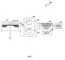
- FIG. 1 illustrates a block diagram of a multi-range pressure sensor apparatus with multiple signal paths, which can be implemented in accordance with a preferred embodiment
- FIG. 2 illustrates a schematic diagram of the multi-range pressure sensor apparatus with multiple signal paths, in accordance with a preferred embodiment
- FIG. 3 illustrates a flow chart of operations illustrating logical operational steps of a method for sensing broad ranges of pressures with high accuracy utilizing the multi-range pressure sensor apparatus with a single sense die and multiple signal paths, which can be implemented in accordance with an alternative embodiment.
- FIG. 1 illustrates a block diagram of a multi-range pressure sensor apparatus 100 with multiple signal paths, which can be implemented in accordance with a preferred embodiment.
- the pressure sensor apparatus 100 generally includes a pressure transducer 110, an amplifier circuit 130, and a programmable compensation circuit 140.
- the programmable compensation circuit 140 can be implemented in the form of an integrated circuit.
- the pressure transducer 110, amplifier circuit 130, and programmable compensation circuit 140 are capable of communicating electrically with one another.
- the pressure transducer 110 generally incorporates a single sense die 115 with a pressure-sensing diaphragm 114.
- the sensor die 115 can also be configured to incorporate a Wheatstone bridge circuit configuration, referred to simply as a "Wheatstone bridge".
- One or more piezoresistors e.g., four piezoresistors
- piezoresistors 112 can be embedded in the diaphragm 114 at locations that maximize the output of the sensor's Wheatstone bridge (not shown).
- the diaphragm 114 can be deformed in accordance with the pressure P1 applied by a media. The deformation can be measured by piezoresistive elements 112 doped on a surface of the diaphragm 114.
- the piezoresistive elements 112 can convert the deformation of the diaphragm 114 into electrical signals utilizing well-known piezoresistive principles in order to compute the pressure in the media. As shown in FIG. 1 , a pressure is applied to the sense die 115 as indicated by arrow P1. A sensed output signal 120 from the pressure transducer 110 can be fed to an amplifier circuit 130, comprising a number of amplifiers A1-An. The amplifier circuit 130 amplifies the low-level output 120 in milli-volts to a high-level amplified output in the range of about one volt to five volts maximum. Multiple signal paths such as signal path 133 and 135 from the amplifier circuit 130 can then be transferred to a programmable compensation circuit 140 associated with a memory 150.
- the programmable compensation circuit 140 possesses the ability to multiplex the amplified output signals 133 and 135 and provide a digital output 160.
- the multiple signal paths 133 and 135, each path having a different gain, allows for multiple compensated ranges in the single transducer 110.
- Such an apparatus 100 can be exposed to large overpressures without being damaged. Also, the apparatus 100 can be exposed to large overpressures without undergoing a significant pressure hysteresis. In other words, subjecting the apparatus 100 to pressures substantially greater than the pressures of the working range of the transducer 110 does not adversely affect the accuracy of the transducer 110 on subsequent measurements within the working range thereof.
- FIG. 2 illustrates a schematic diagram of the multi-range pressure sensor apparatus 100 with multiple signal paths, in accordance with the preferred embodiment. Note that in FIGS. 1-3 , identical, similar parts, or elements are referred by identical reference numerals.
- a piezoelectric pressure sensing network 210 can be formed as an integral part of the pressure sense die 115 to sense flexing of the diaphragm 114 and produce an electrical signal in response thereto.
- the piezoelectric network 210 includes piezoresistors R1, R2, R3 and R4. Electrical connection can be provided for connecting the piezoresistors R1, R2, R3 and R4 to circuitry connection sites for associated sensor circuitry. Conductive leads can be embedded in the die 115 to connect the R1, R2, R3 and R4 in a full Wheatstone bridge configuration.
- the resistors R1 and R3 forms one arm of the Wheatstone bridge 210 while the variable resistor R4 and the fixed resistor R2 make up the other arm of the bridge circuit 210.
- the resistors R1, R2, R3 and R4 can be formed in accordance with well-known metalization techniques of any material having suitable thin film resistance properties and suitable deposition characteristics.
- the resistors R1, R2, R3 and R4 are formed of nickel or platinum. Additional processing or treatment apparent to those skilled in the art can be applied to the surface of pressure sense die 115 to improve robustness with respect to media compatibility and potential ionic contamination.
- the electric signals from the Wheatstone Bridge 210 can be transferred to the amplifiers 233 and 235 and the programmable compensation circuit 140.
- the differential gain can be obtained from the multiple signal paths 133 and 135 generated by the amplifiers 233 and 235 and the direct signal path 137. It will be readily apparent that while two amplifiers 233 and 235 have been illustrated, additional amplifiers for measuring broader operative pressure ranges may be added when larger overall ranges of pressure are to be measured, each of the added amplifiers also furnishing an amplified output signal supplied as an input to the programmable integrated circuit 140.
- the programmable compensation circuit 140 is a versatile integrated circuit chip, the internal circuitry of which may be configured by an individual user to realize a user-specific circuit.
- the user configures an on-chip interconnect structure of the programmable IC 140 so that selected input terminals such as VBN, EXTTEMP, VDD_1, VBP, BSINK and selected output terminals such as VGATE, VDD, SIG_PD_DIAG, SIG_PD, VSSA, VSS of selected on-chip circuit components are electrically connected together in such a way that the resulting circuit is the user-specific circuit desired by the user.
- the programmable compensation circuit 140 receives signals 133 and 135 and the direct signal 137 to produce the separate compensation for each of the different signal paths. Such compensation values can be stored in the memory 150 for each signal path, which allows high accuracy compensation at low system cost.
- the sensor apparatus 100 comprises either a stand-alone memory IC or with memory integral to the programmable compensation circuit 140, which provides separate compensations for each of the different signal paths. Such an approach removes errors due to amplifier gain and offset.
- FIG. 3 illustrates a flow chart of operations illustrating logical operational steps of a method 300 for sensing broad ranges of pressures with high accuracy utilizing the multi-range pressure sensor apparatus 100 with a single sense die and multiple signal paths, which can be implemented in accordance with an alternative embodiment.
- a single sense die 115 of the pressure transducer 110 can be connected to the amplifier circuit 130 comprising one or more amplifiers 233 and 235, as depicted at block 310. Thereafter, as indicated at block 320, the sensed output signal from the pressure transducer 110 can be transferred to the amplifier circuits 130.
- the multiple signal paths 133 and 135, having a different gain from amplifier circuits 130, can then be transferred to a programmable compensation circuit 140, as illustrated at block 330.
- the different input signals 133 and 135 can be multiplexed utilizing programmable compensation circuit 140 in order to provide digital output 160, for which compensation values can be provided, as depicted at block 340.
- the compensation values for each of the different signal paths 133 and 135 can be stored in the memory 150 integrated to the programmable integrated circuit 140 to allow high accuracy compensation, as indicated at block 350.
- the multi-range pressure sensor apparatus 100 detects broad ranges of pressure with high-pressure compensation, as shown at block 360.
- the multiple signal paths of the sense die 115 with potentially different compensation values stored for each path can generate high accuracy compensations at a low system cost.
- Each path of the multiple signal paths possesses a different gain that can provide multiple compensated ranges in the pressure sensor.
- the amplifier circuits 140 of the pressure sensor 110 can be integral to the sense die 115, integral to the programmable compensation circuit 140, or isolated to provide error free output generated due to amplifier gain and offset.
Landscapes
- Physics & Mathematics (AREA)
- General Physics & Mathematics (AREA)
- Measuring Fluid Pressure (AREA)
Abstract
Description
- This application claims priority to
U.S. Provisional Patent Application Serial No. 61/139,319 - Embodiments are generally related to sensor devices, methods, and systems. Embodiments are also related to multi-range pressure sensor devices capable of detecting a variety of parameters under varying conditions.
- The need for accurate, low cost, compact pressure sensors capable of a broad range of measurement is becoming increasingly necessary in a variety of commercial, industrial, military and other applications. Measurement of a broad range of pressures is particularly challenging because of an enormous range of pressures that can be realized. Conventional pressure sensors possess an extremely limited range of pressure measurement capabilities and often cannot be operated over their maximum potential measuring ranges due to their technical design. Additionally, when an anticipated force exceeds the capacity of an individual pressure sensor, multiple pressure sensors having ranges of measurement adjoining one another must be utilized simultaneously.
- Furthermore, the arrangement of multiple sensors is correspondingly more complicated. The output signals of the sensors are generally not compatible with one another and must therefore be evaluated in an additional, external electronic circuit in order to recognize which of the sensors is functioning in the permitted range of measurement at a given moment. In such an approach, excessive expenditures of time and money are required to incorporate multiple sensors within a single system. In addition, such the use of two or more independent pressure sensors requires protective valves to avoid damage with respect to more accurate sensors at high pressures.
- Based on the foregoing, it is believed that a need exists for an improved multi-range pressure sensor apparatus that is capable of efficiently detecting a broad range of pressures with high accuracy and in a very narrow range, as described in greater detail herein.
- The following summary is provided to facilitate an understanding of some of the innovative features unique to the embodiments disclosed and is not intended to be a full description. A full appreciation of the various aspects of the embodiments can be gained by taking the entire specification, claims, drawings, and abstract as a whole.
- It is, therefore, one aspect of the present invention to provide for an improved pressure sensor apparatus, system, and method.
- It is another aspect of the present invention to provide for an improved pressure sensor apparatus, system, and method that incorporates the use of a single sense die and multiple signal paths for detecting broad ranges of pressures with high accuracy.
- It is a further aspect of the present invention to provide for an improved method, apparatus, and system for removing errors due to amplifier gain and offset.
- The aforementioned aspects and other objectives and advantages can now be achieved as described herein. A multi-range pressure sensor apparatus, method, and system having multiple signal paths for detecting broad ranges of pressures with high accuracy are disclosed. A pressure transducer can be configured that includes a pressure sense die with piezoresistive elements integrated into a sensor die in a Wheatstone bridge configuration. A sensed output signal from the sense die can be transferred to one or more amplifier circuits. A programmable compensation integrated circuit can be utilized to multiplex different amplified output signals from each of the amplifier circuits and to provide a digital output. A memory associated with the programmable compensation integrated circuit can be configured to provide separate compensations stored with respect to each of the different signal paths and capable of removing errors due to amplifier gain and offset.
- The multiple signal paths from the amplifier circuits with potentially different compensation values stored for each path can generate high accuracy compensations at a low system cost. Each path of the multiple signal paths possesses a different gain that is capable of providing multiple compensated ranges in the pressure sensor. In one embodiment, the amplifier circuits of the pressure sensor can be integral to the sense die and/or integral to the programmable compensation circuit. In another embodiment, the amplifier circuits may be isolated to provide error free output generated due to amplifier gain and offset. Such a multi-range pressure sensor apparatus provides a broad measurement range and high accuracy in a very narrow range.
- The accompanying figures, in which like reference numerals refer to identical or functionally-similar elements throughout the separate views and which are incorporated in and form a part of the specification, further illustrate the embodiments and, together with the detailed description, serve to explain the embodiments disclosed herein.
-
FIG. 1 illustrates a block diagram of a multi-range pressure sensor apparatus with multiple signal paths, which can be implemented in accordance with a preferred embodiment; -
FIG. 2 illustrates a schematic diagram of the multi-range pressure sensor apparatus with multiple signal paths, in accordance with a preferred embodiment; and -
FIG. 3 illustrates a flow chart of operations illustrating logical operational steps of a method for sensing broad ranges of pressures with high accuracy utilizing the multi-range pressure sensor apparatus with a single sense die and multiple signal paths, which can be implemented in accordance with an alternative embodiment. - The particular values and configurations discussed in these non-limiting examples can be varied and are cited merely to illustrate at least one embodiment and are not intended to limit the scope thereof.
-
FIG. 1 illustrates a block diagram of a multi-rangepressure sensor apparatus 100 with multiple signal paths, which can be implemented in accordance with a preferred embodiment. Thepressure sensor apparatus 100 generally includes apressure transducer 110, anamplifier circuit 130, and aprogrammable compensation circuit 140. Note that theprogrammable compensation circuit 140 can be implemented in the form of an integrated circuit. Thepressure transducer 110,amplifier circuit 130, andprogrammable compensation circuit 140 are capable of communicating electrically with one another. Thepressure transducer 110 generally incorporates a single sense die 115 with a pressure-sensing diaphragm 114. - The
sensor die 115 can also be configured to incorporate a Wheatstone bridge circuit configuration, referred to simply as a "Wheatstone bridge". One or more piezoresistors (e.g., four piezoresistors) such as piezoresistors 112 can be embedded in the diaphragm 114 at locations that maximize the output of the sensor's Wheatstone bridge (not shown). The diaphragm 114 can be deformed in accordance with the pressure P1 applied by a media. The deformation can be measured by piezoresistive elements 112 doped on a surface of the diaphragm 114. - The piezoresistive elements 112 can convert the deformation of the diaphragm 114 into electrical signals utilizing well-known piezoresistive principles in order to compute the pressure in the media. As shown in
FIG. 1 , a pressure is applied to the sense die 115 as indicated by arrow P1. A sensedoutput signal 120 from thepressure transducer 110 can be fed to anamplifier circuit 130, comprising a number of amplifiers A1-An. Theamplifier circuit 130 amplifies the low-level output 120 in milli-volts to a high-level amplified output in the range of about one volt to five volts maximum. Multiple signal paths such assignal path amplifier circuit 130 can then be transferred to aprogrammable compensation circuit 140 associated with amemory 150. Theprogrammable compensation circuit 140 possesses the ability to multiplex the amplifiedoutput signals digital output 160. Themultiple signal paths single transducer 110. - Such an
apparatus 100 can be exposed to large overpressures without being damaged. Also, theapparatus 100 can be exposed to large overpressures without undergoing a significant pressure hysteresis. In other words, subjecting theapparatus 100 to pressures substantially greater than the pressures of the working range of thetransducer 110 does not adversely affect the accuracy of thetransducer 110 on subsequent measurements within the working range thereof. -
FIG. 2 illustrates a schematic diagram of the multi-rangepressure sensor apparatus 100 with multiple signal paths, in accordance with the preferred embodiment. Note that inFIGS. 1-3 , identical, similar parts, or elements are referred by identical reference numerals. A piezoelectricpressure sensing network 210 can be formed as an integral part of the pressure sense die 115 to sense flexing of the diaphragm 114 and produce an electrical signal in response thereto. Thepiezoelectric network 210 includes piezoresistors R1, R2, R3 and R4. Electrical connection can be provided for connecting the piezoresistors R1, R2, R3 and R4 to circuitry connection sites for associated sensor circuitry. Conductive leads can be embedded in thedie 115 to connect the R1, R2, R3 and R4 in a full Wheatstone bridge configuration. - The resistors R1 and R3 forms one arm of the Wheatstone
bridge 210 while the variable resistor R4 and the fixed resistor R2 make up the other arm of thebridge circuit 210. In the circuit configuration ofFIG. 2 , there is maximum pressure sensitivity when the piezoresistors R1, R2, R3 and R4 have similar resistances, each varying with the magnitude of the strain to which they are exposed. The resistors R1, R2, R3 and R4 can be formed in accordance with well-known metalization techniques of any material having suitable thin film resistance properties and suitable deposition characteristics. Preferably, the resistors R1, R2, R3 and R4 are formed of nickel or platinum. Additional processing or treatment apparent to those skilled in the art can be applied to the surface of pressure sense die 115 to improve robustness with respect to media compatibility and potential ionic contamination. - The electric signals from the
Wheatstone Bridge 210 can be transferred to theamplifiers 233 and 235 and theprogrammable compensation circuit 140. The differential gain can be obtained from themultiple signal paths amplifiers 233 and 235 and thedirect signal path 137. It will be readily apparent that while twoamplifiers 233 and 235 have been illustrated, additional amplifiers for measuring broader operative pressure ranges may be added when larger overall ranges of pressure are to be measured, each of the added amplifiers also furnishing an amplified output signal supplied as an input to the programmableintegrated circuit 140. - The
programmable compensation circuit 140 is a versatile integrated circuit chip, the internal circuitry of which may be configured by an individual user to realize a user-specific circuit. For example, to configure aprogrammable compensation circuit 140, the user configures an on-chip interconnect structure of theprogrammable IC 140 so that selected input terminals such as VBN, EXTTEMP, VDD_1, VBP, BSINK and selected output terminals such as VGATE, VDD, SIG_PD_DIAG, SIG_PD, VSSA, VSS of selected on-chip circuit components are electrically connected together in such a way that the resulting circuit is the user-specific circuit desired by the user. Theprogrammable compensation circuit 140 receivessignals direct signal 137 to produce the separate compensation for each of the different signal paths. Such compensation values can be stored in thememory 150 for each signal path, which allows high accuracy compensation at low system cost. Thesensor apparatus 100 comprises either a stand-alone memory IC or with memory integral to theprogrammable compensation circuit 140, which provides separate compensations for each of the different signal paths. Such an approach removes errors due to amplifier gain and offset. -
FIG. 3 illustrates a flow chart of operations illustrating logical operational steps of amethod 300 for sensing broad ranges of pressures with high accuracy utilizing the multi-rangepressure sensor apparatus 100 with a single sense die and multiple signal paths, which can be implemented in accordance with an alternative embodiment. A single sense die 115 of thepressure transducer 110 can be connected to theamplifier circuit 130 comprising one ormore amplifiers 233 and 235, as depicted atblock 310. Thereafter, as indicated atblock 320, the sensed output signal from thepressure transducer 110 can be transferred to theamplifier circuits 130. Themultiple signal paths amplifier circuits 130, can then be transferred to aprogrammable compensation circuit 140, as illustrated atblock 330. The different input signals 133 and 135 can be multiplexed utilizingprogrammable compensation circuit 140 in order to providedigital output 160, for which compensation values can be provided, as depicted atblock 340. - The compensation values for each of the
different signal paths memory 150 integrated to the programmableintegrated circuit 140 to allow high accuracy compensation, as indicated atblock 350. The multi-rangepressure sensor apparatus 100 detects broad ranges of pressure with high-pressure compensation, as shown atblock 360. The multiple signal paths of the sense die 115 with potentially different compensation values stored for each path can generate high accuracy compensations at a low system cost. Each path of the multiple signal paths possesses a different gain that can provide multiple compensated ranges in the pressure sensor. Theamplifier circuits 140 of thepressure sensor 110 can be integral to the sense die 115, integral to theprogrammable compensation circuit 140, or isolated to provide error free output generated due to amplifier gain and offset. - It will be appreciated that variations of the above-disclosed and other features and functions, or alternatives thereof, may be desirably combined into many other different systems or applications. Also that various presently unforeseen or unanticipated alternatives, modifications, variations or improvements therein may be subsequently made by those skilled in the art which are also intended to be encompassed by the following claims.
Claims (11)
- A multi-range pressure sensor apparatus (100), comprising:a pressure transducer (110) comprising a sense die (115) having a plurality of piezoresistive elements (112) situated in a bridge configuration for transducing a pressure force into an electrical output signal;at least two amplifiers (233, 235), each of the at least two amplifiers (233, 235) having an input and an output, wherein the input of each of the at least two amplifiers is electrically coupled to the electrical output signal (120) of the pressure transducer (110), and each of the at least two amplifiers (233, 235) has a different gain than the other of the at least two amplifiers (233, 235); anda programmable compensation circuit (140) coupled to the outputs of the at least two amplifiers (233, 235), wherein said programmable compensation circuit (140) is capable of selecting between the outputs of the at least two amplifiers (233, 235) to produce a digital output (160) that corresponds to the selected amplifier output.
- The apparatus of the claim 1, wherein the programmable compensation circuit (140) includes a memory (150) that stores separate compensations for each of the at least two amplifiers (233, 235).
- The apparatus of the claim 2 wherein said memory (150) is integral to said programmable compensation circuit (140).
- The apparatus of the claim 1 wherein said programmable compensation circuit (140) is capable of selecting between the outputs of the at least two amplifiers (233, 235), applying the compensations that corresponding to the selected amplifier output, and generating a digital output (160) that corresponds to the selected amplifier output.
- The apparatus of the claim 1 wherein said programmable compensation circuit (140) includes a multiplexer for selecting between the outputs of the at least two amplifiers (233, 235).
- A multi-range pressure sensing method, said method comprising:sensing a fluid pressure;transducing the fluid pressure into an electrical output signal (120);amplifying the electrical output signal (120) with a first amplifier (233) having a first gain to produce a first amplifier output signal (133);amplifying the electrical output signal (120) with a second amplifier (235) having a second gain to produce a second amplifier output signal (135), wherein the second gain is different from the first gain;selecting one of the a first amplifier output signal (133) or second amplifier output signal (135), resulting in a selected amplifier output signal;applying compensation parameters to the selected amplifier output signal, wherein the applied compensation parameters are dependent on whether the first amplifier output signal (133) or second amplifier output signal (135) was selected; andoutputting a compensated output signal (160).
- The method of the claim 6 comprising:selecting the first amplifier output signal (133), applying compensation parameters that correspond to the first amplifier output signal (133), and outputting a first compensated output signal (160); and thenselecting the second amplifier output signal (135), applying compensation parameters that correspond to the second amplifier output signal (135), and outputting a second compensated output signal (160).
- The method of the claim 6 wherein the selecting step selects the first amplifier output signal (133) when the fluid pressure is below a first threshold value.
- The method of claim 8, wherein the selecting step selects the second amplifier output signal (135) when the fluid pressure is above the first threshold value.
- The method of the claim 6, wherein said applying step is performed using a programmable compensation device (140).
- The method of the claim 6, wherein said selecting step is performed using a multiplexer.
Applications Claiming Priority (2)
| Application Number | Priority Date | Filing Date | Title |
|---|---|---|---|
| US13931908P | 2008-12-19 | 2008-12-19 | |
| US12/389,042 US7950286B2 (en) | 2008-12-19 | 2009-02-19 | Multi-range pressure sensor apparatus and method utilizing a single sense die and multiple signal paths |
Publications (3)
| Publication Number | Publication Date |
|---|---|
| EP2199770A2 true EP2199770A2 (en) | 2010-06-23 |
| EP2199770A3 EP2199770A3 (en) | 2012-01-18 |
| EP2199770B1 EP2199770B1 (en) | 2012-08-29 |
Family
ID=42040441
Family Applications (1)
| Application Number | Title | Priority Date | Filing Date |
|---|---|---|---|
| EP09178993A Active EP2199770B1 (en) | 2008-12-19 | 2009-12-11 | Multi-range pressure sensor apparatus and method utilizing a single sense die and multiple signal paths |
Country Status (3)
| Country | Link |
|---|---|
| US (2) | US7950286B2 (en) |
| EP (1) | EP2199770B1 (en) |
| CN (1) | CN101788350B (en) |
Cited By (7)
| Publication number | Priority date | Publication date | Assignee | Title |
|---|---|---|---|---|
| ITTO20110422A1 (en) * | 2011-05-12 | 2012-11-13 | Elbi Int Spa | ELECTRODYNAMIC POSITION TRANSDUCER DEVICE, AND WASHING MACHINE INCLUDING SUCH A DEVICE |
| WO2013135661A1 (en) * | 2012-03-13 | 2013-09-19 | Robert Bosch Gmbh | Pressure-measuring assembly |
| FR2991451A1 (en) * | 2012-05-31 | 2013-12-06 | Continental Automotive France | Method for processing signal of pressure measurement device in internal combustion engine, involves applying adjustable gain as predetermined function, so that adjustable gain reaches maximum value equal to nominal gain value |
| CN104483062A (en) * | 2014-12-23 | 2015-04-01 | 中国电子科技集团公司第四十九研究所 | High-reliability redundancy differential pressure sensor |
| CN105181238A (en) * | 2015-06-04 | 2015-12-23 | 苏州科技学院 | Device for adjusting zero point and measuring range of ceramic pressure sensor |
| GB2559834A (en) * | 2017-02-16 | 2018-08-22 | Sensata Technologies Inc | Dual output pressure sensor with single pressure transducer element |
| EP3722765A1 (en) | 2019-04-09 | 2020-10-14 | Honeywell International Inc. | Load cell |
Families Citing this family (20)
| Publication number | Priority date | Publication date | Assignee | Title |
|---|---|---|---|---|
| US7950286B2 (en) * | 2008-12-19 | 2011-05-31 | Honeywell International Inc. | Multi-range pressure sensor apparatus and method utilizing a single sense die and multiple signal paths |
| US7997143B2 (en) | 2009-04-09 | 2011-08-16 | Kulite Semiconductor Products, Inc. | Internally switched multiple range transducer |
| US10330513B2 (en) * | 2009-05-27 | 2019-06-25 | Honeywell International Inc. | Multi-dynamic-range sensor |
| US8656772B2 (en) | 2010-03-22 | 2014-02-25 | Honeywell International Inc. | Flow sensor with pressure output signal |
| US8616065B2 (en) * | 2010-11-24 | 2013-12-31 | Honeywell International Inc. | Pressure sensor |
| US8498829B2 (en) | 2010-11-29 | 2013-07-30 | Infineon Technologies Ag | Pressure monitoring circuits and methods |
| US8695417B2 (en) | 2011-01-31 | 2014-04-15 | Honeywell International Inc. | Flow sensor with enhanced flow range capability |
| US8446220B2 (en) | 2011-05-09 | 2013-05-21 | Honeywell International Inc. | Method and apparatus for increasing the effective resolution of a sensor |
| US8770034B2 (en) | 2011-09-06 | 2014-07-08 | Honeywell International Inc. | Packaged sensor with multiple sensors elements |
| CN103077105A (en) * | 2011-10-25 | 2013-05-01 | 宏碁股份有限公司 | Screen squeeze protector and method thereof |
| US9581483B2 (en) | 2012-03-23 | 2017-02-28 | Honeywell International, Inc. | Tank overflow protection system and method |
| US9052217B2 (en) | 2012-11-09 | 2015-06-09 | Honeywell International Inc. | Variable scale sensor |
| US9470593B2 (en) | 2013-09-12 | 2016-10-18 | Honeywell International Inc. | Media isolated pressure sensor |
| US9706294B2 (en) * | 2015-03-18 | 2017-07-11 | Infineon Technologies Ag | System and method for an acoustic transducer and environmental sensor package |
| JP2017037040A (en) * | 2015-08-13 | 2017-02-16 | 富士電機株式会社 | Semiconductor physical quantity sensor device and method for manufacturing semiconductor physical quantity sensor device |
| US10101233B2 (en) | 2016-05-24 | 2018-10-16 | Kulite Semiconductor Products, Inc. | Systems and methods for switched multi-transducer pressure sensors and compensation thereof |
| US9869598B1 (en) * | 2016-06-24 | 2018-01-16 | Honeywell International Inc. | Low cost small force sensor |
| JP2019012013A (en) * | 2017-06-30 | 2019-01-24 | セイコーエプソン株式会社 | Force detection device and robot |
| US10718678B2 (en) | 2018-03-30 | 2020-07-21 | Hamilton Sundstrand Corporation | Aircraft engine multi-channel pressure transducer |
| CN119394503B (en) * | 2024-10-29 | 2025-10-31 | 精奇(天津)科技股份有限公司 | A multi-channel programmable explosion-proof digital display pressure sensor |
Family Cites Families (63)
| Publication number | Priority date | Publication date | Assignee | Title |
|---|---|---|---|---|
| US3484732A (en) | 1967-12-07 | 1969-12-16 | Robert W Postma | Dual range pressure sensor |
| US4501144A (en) | 1982-09-30 | 1985-02-26 | Honeywell Inc. | Flow sensor |
| US4478076A (en) | 1982-09-30 | 1984-10-23 | Honeywell Inc. | Flow sensor |
| US4651564A (en) | 1982-09-30 | 1987-03-24 | Honeywell Inc. | Semiconductor device |
| US4478077A (en) | 1982-09-30 | 1984-10-23 | Honeywell Inc. | Flow sensor |
| US4683159A (en) | 1982-09-30 | 1987-07-28 | Honeywell Inc. | Semiconductor device structure and processing |
| US4574640A (en) | 1984-11-29 | 1986-03-11 | Bourns Instruments, Inc. | Integrated dual-range pressure transducer |
| DE3446248A1 (en) * | 1984-12-19 | 1986-06-19 | Robert Bosch Gmbh, 7000 Stuttgart | SENSOR FOR MEASURING PHYSICAL SIZES AND METHOD FOR ADJUSTING THE SENSOR |
| JP2544435B2 (en) | 1988-04-06 | 1996-10-16 | 株式会社日立製作所 | Multi-function sensor |
| US5089979A (en) * | 1989-02-08 | 1992-02-18 | Basic Measuring Instruments | Apparatus for digital calibration of detachable transducers |
| JP3071202B2 (en) * | 1989-07-19 | 2000-07-31 | 富士電機株式会社 | Semiconductor pressure sensor amplification compensation circuit |
| US5050429A (en) | 1990-02-22 | 1991-09-24 | Yamatake-Honeywell Co., Ltd. | Microbridge flow sensor |
| US5099695A (en) * | 1990-04-23 | 1992-03-31 | Smc Corporation | Pressure detection apparatus |
| US5321638A (en) * | 1990-04-30 | 1994-06-14 | Witney Keith C | Calibrated sensor systems and methods of manufacturing same |
| US5193393A (en) * | 1991-02-04 | 1993-03-16 | Motorola, Inc. | Pressure sensor circuit |
| US5187985A (en) * | 1991-09-19 | 1993-02-23 | Honeywell Inc. | Amplified pressure transducer |
| US5398194A (en) * | 1991-11-22 | 1995-03-14 | Kulite Semiconductor Products, Inc. | Electronic sensing circuit using piezoresistors |
| US5347476A (en) * | 1992-11-25 | 1994-09-13 | Mcbean Sr Ronald V | Instrumentation system with multiple sensor modules |
| JP2768219B2 (en) * | 1993-06-24 | 1998-06-25 | 日本電気株式会社 | Distortion amount detection device, drive circuit thereof, and amplifier circuit |
| JP2991014B2 (en) * | 1993-10-08 | 1999-12-20 | 三菱電機株式会社 | Pressure sensor |
| US5507171A (en) * | 1994-04-15 | 1996-04-16 | Ssi Technologies, Inc. | Electronic circuit for a transducer |
| US5578962A (en) * | 1995-05-10 | 1996-11-26 | Mca Technologies, Inc. | Instrumentation amplifier for sensor signal conditioning using low-cost, high-accuracy analog circuitry |
| US5668320A (en) * | 1995-06-19 | 1997-09-16 | Cardiometrics, Inc. | Piezoresistive pressure transducer circuitry accommodating transducer variability |
| DE19533505A1 (en) * | 1995-09-04 | 1997-03-06 | Siemens Ag | Method for compensating for the incorrect behavior of measuring devices caused by an external influencing variable |
| JP2001511884A (en) * | 1996-07-10 | 2001-08-14 | ハネウェル データ インスツルメンツ インコーポレイテッド | Pressure transducer with error compensation |
| US6047244A (en) | 1997-12-05 | 2000-04-04 | Rosemount Inc. | Multiple range transition method and apparatus for process control sensors |
| US6234016B1 (en) | 1997-12-31 | 2001-05-22 | Honeywell International Inc. | Time lag approach for measuring fluid velocity |
| US6223593B1 (en) | 1997-12-31 | 2001-05-01 | Honeywell International Inc. | Self-oscillating fluid sensor |
| US6169965B1 (en) | 1997-12-31 | 2001-01-02 | Honeywell International Inc. | Fluid property and flow sensing via a common frequency generator and FFT |
| DE69942735D1 (en) | 1998-12-10 | 2010-10-21 | Lucent Technologies Inc | PABX management |
| US6502459B1 (en) | 2000-09-01 | 2003-01-07 | Honeywell International Inc. | Microsensor for measuring velocity and angular direction of an incoming air stream |
| US7239957B1 (en) | 2000-10-06 | 2007-07-03 | Visteon Global Technologies, Inc. | Method and system for seamless transition between multiple feedback ranges |
| JP2002148131A (en) * | 2000-11-10 | 2002-05-22 | Denso Corp | Physical quantity detector |
| US6450005B1 (en) * | 2000-12-21 | 2002-09-17 | Honeywell International Inc. | Method and apparatus for the calibration and compensation of sensors |
| US6684711B2 (en) * | 2001-08-23 | 2004-02-03 | Rosemount Inc. | Three-phase excitation circuit for compensated capacitor industrial process control transmitters |
| JP4082901B2 (en) * | 2001-12-28 | 2008-04-30 | 忠弘 大見 | Pressure sensor, pressure control device, and temperature drift correction device for pressure flow control device |
| US6653959B1 (en) | 2002-05-22 | 2003-11-25 | Massachusetts Institute Of Technology | High dynamic range analog-to-digital converter having parallel equalizers |
| JP4059056B2 (en) * | 2002-10-18 | 2008-03-12 | 株式会社デンソー | Sensor device and output characteristic switching method of sensor device |
| WO2004079306A1 (en) | 2003-03-04 | 2004-09-16 | Cidra Corporation | An apparatus having a multi-band sensor assembly for measuring a parameter of a fluid flow flowing within a pipe |
| US7194919B2 (en) | 2003-05-29 | 2007-03-27 | Transonic Systems, Inc. | Acoustically coupled ultrasonic transit time flow sensors |
| WO2005106403A2 (en) | 2004-04-21 | 2005-11-10 | Therm-O-Disc, Inc | Multi-function sensor |
| US7206700B2 (en) * | 2004-07-23 | 2007-04-17 | Baylor University | Method and machine for identifying a chemical compound |
| TWI235824B (en) * | 2004-08-17 | 2005-07-11 | Taiwan Silicon Microelectronic | The temperature compensating method of a digital pressure gauge |
| US7185538B2 (en) | 2004-11-12 | 2007-03-06 | Honeywell International Inc. | Methods and systems for sensing air vehicle airspeed |
| US7527742B2 (en) | 2005-06-27 | 2009-05-05 | Momentive Performance Materials Inc. | Etchant, method of etching, laminate formed thereby, and device |
| US7117747B2 (en) * | 2005-01-03 | 2006-10-10 | Delphi Technologies, Inc. | Integrated pressure sensor and method of manufacture |
| US7635077B2 (en) | 2005-09-27 | 2009-12-22 | Honeywell International Inc. | Method of flip chip mounting pressure sensor dies to substrates and pressure sensors formed thereby |
| US7318351B2 (en) | 2005-10-05 | 2008-01-15 | Honeywell International Inc. | Pressure sensor |
| US7258016B2 (en) * | 2005-12-21 | 2007-08-21 | Honeywell International Inc. | Pressure sensor with electronic datasheet |
| US7266999B2 (en) | 2006-01-30 | 2007-09-11 | Honeywell International Inc. | Thick film technology based ultra high pressure sensor utilizing integral port and diaphragm construction |
| US20070197922A1 (en) | 2006-02-17 | 2007-08-23 | Honeywell International Inc. | Disposable pressure sensor systems and packages therefor |
| US7377177B1 (en) * | 2007-04-13 | 2008-05-27 | Honeywell International Inc. | Pressure sensor method and apparatus |
| US8010322B2 (en) * | 2006-05-17 | 2011-08-30 | Honeywell International Inc. | Signal conditioning IC with conditioning-coefficient memory |
| US8175835B2 (en) * | 2006-05-17 | 2012-05-08 | Honeywell International Inc. | Flow sensor with conditioning-coefficient memory |
| US7343812B2 (en) | 2006-06-15 | 2008-03-18 | Honeywell International Inc. | Method to reduce die edge shorting on pressure sensors using conductive elastomeric seals |
| US7520051B2 (en) * | 2007-01-04 | 2009-04-21 | Honeywell International Inc. | Packaging methods and systems for measuring multiple measurands including bi-directional flow |
| CN101236113B (en) * | 2007-02-01 | 2011-03-16 | 上海飞恩微电子有限公司 | All-bridge type piezoresistance type pressure sensor digital type signal conditioning chip |
| US7458274B2 (en) | 2007-02-20 | 2008-12-02 | Honeywell International Inc. | Pressure sensor incorporating a compliant pin |
| US7759945B2 (en) * | 2007-08-22 | 2010-07-20 | Honeywell International Inc. | Sensor including dual range, application specific integrated chip (ASIC) |
| US7995124B2 (en) | 2007-09-14 | 2011-08-09 | Omnivision Technologies, Inc. | Image sensor apparatus and method for improved dynamic range with multiple readout circuit paths |
| US7769557B2 (en) * | 2008-07-01 | 2010-08-03 | Honeywell International Inc. | Multi-gas flow sensor with gas specific calibration capability |
| US7950286B2 (en) * | 2008-12-19 | 2011-05-31 | Honeywell International Inc. | Multi-range pressure sensor apparatus and method utilizing a single sense die and multiple signal paths |
| US10330513B2 (en) * | 2009-05-27 | 2019-06-25 | Honeywell International Inc. | Multi-dynamic-range sensor |
-
2009
- 2009-02-19 US US12/389,042 patent/US7950286B2/en active Active
- 2009-12-11 EP EP09178993A patent/EP2199770B1/en active Active
- 2009-12-18 CN CN200911000155.0A patent/CN101788350B/en active Active
-
2011
- 2011-03-22 US US13/069,127 patent/US8490496B2/en active Active
Cited By (15)
| Publication number | Priority date | Publication date | Assignee | Title |
|---|---|---|---|---|
| ITTO20110422A1 (en) * | 2011-05-12 | 2012-11-13 | Elbi Int Spa | ELECTRODYNAMIC POSITION TRANSDUCER DEVICE, AND WASHING MACHINE INCLUDING SUCH A DEVICE |
| WO2012153304A1 (en) * | 2011-05-12 | 2012-11-15 | Elbi International S.P.A. | Electrodynamic position transducer device and a washing machine comprising such a device |
| US10030329B2 (en) | 2011-05-12 | 2018-07-24 | Elbi International S.P.A. | Electrodynamic position transducer device and a washing machine comprising such a device |
| WO2013135661A1 (en) * | 2012-03-13 | 2013-09-19 | Robert Bosch Gmbh | Pressure-measuring assembly |
| FR2991451A1 (en) * | 2012-05-31 | 2013-12-06 | Continental Automotive France | Method for processing signal of pressure measurement device in internal combustion engine, involves applying adjustable gain as predetermined function, so that adjustable gain reaches maximum value equal to nominal gain value |
| CN104483062B (en) * | 2014-12-23 | 2016-08-03 | 中国电子科技集团公司第四十九研究所 | Highly reliable redundance differential pressure pickup |
| CN104483062A (en) * | 2014-12-23 | 2015-04-01 | 中国电子科技集团公司第四十九研究所 | High-reliability redundancy differential pressure sensor |
| CN105181238A (en) * | 2015-06-04 | 2015-12-23 | 苏州科技学院 | Device for adjusting zero point and measuring range of ceramic pressure sensor |
| GB2559834A (en) * | 2017-02-16 | 2018-08-22 | Sensata Technologies Inc | Dual output pressure sensor with single pressure transducer element |
| US10337938B2 (en) | 2017-02-16 | 2019-07-02 | Sensata Technologies, Inc. | Dual output pressure sensor with single pressure transducer element |
| GB2559834B (en) * | 2017-02-16 | 2020-02-26 | Sensata Technologies Inc | Dual output pressure sensor with single pressure transducer element |
| EP3722765A1 (en) | 2019-04-09 | 2020-10-14 | Honeywell International Inc. | Load cell |
| US11156511B2 (en) | 2019-04-09 | 2021-10-26 | Honeywell International Inc. | Load cell |
| EP3919881A1 (en) | 2019-04-09 | 2021-12-08 | Honeywell International Inc. | Load cell |
| US11747226B2 (en) | 2019-04-09 | 2023-09-05 | Honeywell International Inc. | Load cell |
Also Published As
| Publication number | Publication date |
|---|---|
| EP2199770B1 (en) | 2012-08-29 |
| CN101788350B (en) | 2014-03-12 |
| EP2199770A3 (en) | 2012-01-18 |
| US20110179879A1 (en) | 2011-07-28 |
| US7950286B2 (en) | 2011-05-31 |
| CN101788350A (en) | 2010-07-28 |
| US20100154551A1 (en) | 2010-06-24 |
| US8490496B2 (en) | 2013-07-23 |
Similar Documents
| Publication | Publication Date | Title |
|---|---|---|
| EP2199770B1 (en) | Multi-range pressure sensor apparatus and method utilizing a single sense die and multiple signal paths | |
| CN106878893B (en) | System and method for sensor-supported microphones | |
| US5507171A (en) | Electronic circuit for a transducer | |
| CN106124095B (en) | Pressure Sensor | |
| EP0975983B1 (en) | Capacitance detection system and method | |
| CN107782485B (en) | Differential pressure sensor integrated with common mode error compensation | |
| US9291516B2 (en) | Internally switched multiple range transducers | |
| EP0533389A2 (en) | Amplified pressure transducer | |
| CN110932690B (en) | Amplifier with common mode detection | |
| US10183859B2 (en) | Dual range high precision pressure sensor | |
| US5631602A (en) | Wheatstone bridge amplifier circuit with integrated diagnostic testing | |
| US8910524B2 (en) | Linked bridge pressure transducer assemblies | |
| CN101228422B (en) | Media isolated absolute pressure sensor | |
| US20070295095A1 (en) | Apparatus for providing an output proportional to pressure divided by temperature (P/T) | |
| KR102011005B1 (en) | Integrated pressure and water sensor | |
| US7032456B1 (en) | Isostatic piezoresistive pressure transducer with temperature output | |
| CN109443503B (en) | Detection device | |
| CN119738081A (en) | Pressure transmitter with multi-range pressure sensor | |
| TWI577978B (en) | Impedance sensor and electronic apparatus using the same | |
| JP4352555B2 (en) | Pressure sensor | |
| CN108444638A (en) | Dual output pressure sensor with single pressure transducer element | |
| US11774302B2 (en) | Sensor apparatus | |
| CN218156599U (en) | Wheatstone bridge pressure detection component and electronic equipment | |
| EP4421467A1 (en) | A sensor configuration | |
| JPH04307331A (en) | Complex sensor |
Legal Events
| Date | Code | Title | Description |
|---|---|---|---|
| PUAI | Public reference made under article 153(3) epc to a published international application that has entered the european phase |
Free format text: ORIGINAL CODE: 0009012 |
|
| 17P | Request for examination filed |
Effective date: 20091211 |
|
| AK | Designated contracting states |
Kind code of ref document: A2 Designated state(s): AT BE BG CH CY CZ DE DK EE ES FI FR GB GR HR HU IE IS IT LI LT LU LV MC MK MT NL NO PL PT RO SE SI SK SM TR |
|
| PUAL | Search report despatched |
Free format text: ORIGINAL CODE: 0009013 |
|
| AK | Designated contracting states |
Kind code of ref document: A3 Designated state(s): AT BE BG CH CY CZ DE DK EE ES FI FR GB GR HR HU IE IS IT LI LT LU LV MC MK MT NL NO PL PT RO SE SI SK SM TR |
|
| RIC1 | Information provided on ipc code assigned before grant |
Ipc: G01L 19/02 20060101ALI20111212BHEP Ipc: G01L 9/06 20060101AFI20111212BHEP |
|
| GRAC | Information related to communication of intention to grant a patent modified |
Free format text: ORIGINAL CODE: EPIDOSCIGR1 |
|
| GRAP | Despatch of communication of intention to grant a patent |
Free format text: ORIGINAL CODE: EPIDOSNIGR1 |
|
| GRAS | Grant fee paid |
Free format text: ORIGINAL CODE: EPIDOSNIGR3 |
|
| GRAA | (expected) grant |
Free format text: ORIGINAL CODE: 0009210 |
|
| AK | Designated contracting states |
Kind code of ref document: B1 Designated state(s): AT BE BG CH CY CZ DE DK EE ES FI FR GB GR HR HU IE IS IT LI LT LU LV MC MK MT NL NO PL PT RO SE SI SK SM TR |
|
| REG | Reference to a national code |
Ref country code: GB Ref legal event code: FG4D |
|
| REG | Reference to a national code |
Ref country code: CH Ref legal event code: EP |
|
| REG | Reference to a national code |
Ref country code: AT Ref legal event code: REF Ref document number: 573304 Country of ref document: AT Kind code of ref document: T Effective date: 20120915 |
|
| REG | Reference to a national code |
Ref country code: IE Ref legal event code: FG4D |
|
| REG | Reference to a national code |
Ref country code: DE Ref legal event code: R096 Ref document number: 602009009238 Country of ref document: DE Effective date: 20121025 |
|
| REG | Reference to a national code |
Ref country code: AT Ref legal event code: MK05 Ref document number: 573304 Country of ref document: AT Kind code of ref document: T Effective date: 20120829 |
|
| REG | Reference to a national code |
Ref country code: NL Ref legal event code: VDEP Effective date: 20120829 |
|
| REG | Reference to a national code |
Ref country code: LT Ref legal event code: MG4D Effective date: 20120829 |
|
| PG25 | Lapsed in a contracting state [announced via postgrant information from national office to epo] |
Ref country code: CY Free format text: LAPSE BECAUSE OF FAILURE TO SUBMIT A TRANSLATION OF THE DESCRIPTION OR TO PAY THE FEE WITHIN THE PRESCRIBED TIME-LIMIT Effective date: 20120829 Ref country code: NO Free format text: LAPSE BECAUSE OF FAILURE TO SUBMIT A TRANSLATION OF THE DESCRIPTION OR TO PAY THE FEE WITHIN THE PRESCRIBED TIME-LIMIT Effective date: 20121129 Ref country code: AT Free format text: LAPSE BECAUSE OF FAILURE TO SUBMIT A TRANSLATION OF THE DESCRIPTION OR TO PAY THE FEE WITHIN THE PRESCRIBED TIME-LIMIT Effective date: 20120829 Ref country code: HR Free format text: LAPSE BECAUSE OF FAILURE TO SUBMIT A TRANSLATION OF THE DESCRIPTION OR TO PAY THE FEE WITHIN THE PRESCRIBED TIME-LIMIT Effective date: 20120829 Ref country code: IS Free format text: LAPSE BECAUSE OF FAILURE TO SUBMIT A TRANSLATION OF THE DESCRIPTION OR TO PAY THE FEE WITHIN THE PRESCRIBED TIME-LIMIT Effective date: 20121229 Ref country code: LT Free format text: LAPSE BECAUSE OF FAILURE TO SUBMIT A TRANSLATION OF THE DESCRIPTION OR TO PAY THE FEE WITHIN THE PRESCRIBED TIME-LIMIT Effective date: 20120829 Ref country code: FI Free format text: LAPSE BECAUSE OF FAILURE TO SUBMIT A TRANSLATION OF THE DESCRIPTION OR TO PAY THE FEE WITHIN THE PRESCRIBED TIME-LIMIT Effective date: 20120829 |
|
| PG25 | Lapsed in a contracting state [announced via postgrant information from national office to epo] |
Ref country code: PT Free format text: LAPSE BECAUSE OF FAILURE TO SUBMIT A TRANSLATION OF THE DESCRIPTION OR TO PAY THE FEE WITHIN THE PRESCRIBED TIME-LIMIT Effective date: 20121231 Ref country code: SE Free format text: LAPSE BECAUSE OF FAILURE TO SUBMIT A TRANSLATION OF THE DESCRIPTION OR TO PAY THE FEE WITHIN THE PRESCRIBED TIME-LIMIT Effective date: 20120829 Ref country code: SI Free format text: LAPSE BECAUSE OF FAILURE TO SUBMIT A TRANSLATION OF THE DESCRIPTION OR TO PAY THE FEE WITHIN THE PRESCRIBED TIME-LIMIT Effective date: 20120829 Ref country code: BE Free format text: LAPSE BECAUSE OF FAILURE TO SUBMIT A TRANSLATION OF THE DESCRIPTION OR TO PAY THE FEE WITHIN THE PRESCRIBED TIME-LIMIT Effective date: 20120829 Ref country code: GR Free format text: LAPSE BECAUSE OF FAILURE TO SUBMIT A TRANSLATION OF THE DESCRIPTION OR TO PAY THE FEE WITHIN THE PRESCRIBED TIME-LIMIT Effective date: 20121130 Ref country code: LV Free format text: LAPSE BECAUSE OF FAILURE TO SUBMIT A TRANSLATION OF THE DESCRIPTION OR TO PAY THE FEE WITHIN THE PRESCRIBED TIME-LIMIT Effective date: 20120829 |
|
| PG25 | Lapsed in a contracting state [announced via postgrant information from national office to epo] |
Ref country code: ES Free format text: LAPSE BECAUSE OF FAILURE TO SUBMIT A TRANSLATION OF THE DESCRIPTION OR TO PAY THE FEE WITHIN THE PRESCRIBED TIME-LIMIT Effective date: 20121210 Ref country code: CZ Free format text: LAPSE BECAUSE OF FAILURE TO SUBMIT A TRANSLATION OF THE DESCRIPTION OR TO PAY THE FEE WITHIN THE PRESCRIBED TIME-LIMIT Effective date: 20120829 Ref country code: NL Free format text: LAPSE BECAUSE OF FAILURE TO SUBMIT A TRANSLATION OF THE DESCRIPTION OR TO PAY THE FEE WITHIN THE PRESCRIBED TIME-LIMIT Effective date: 20120829 Ref country code: DK Free format text: LAPSE BECAUSE OF FAILURE TO SUBMIT A TRANSLATION OF THE DESCRIPTION OR TO PAY THE FEE WITHIN THE PRESCRIBED TIME-LIMIT Effective date: 20120829 Ref country code: RO Free format text: LAPSE BECAUSE OF FAILURE TO SUBMIT A TRANSLATION OF THE DESCRIPTION OR TO PAY THE FEE WITHIN THE PRESCRIBED TIME-LIMIT Effective date: 20120829 Ref country code: EE Free format text: LAPSE BECAUSE OF FAILURE TO SUBMIT A TRANSLATION OF THE DESCRIPTION OR TO PAY THE FEE WITHIN THE PRESCRIBED TIME-LIMIT Effective date: 20120829 |
|
| PG25 | Lapsed in a contracting state [announced via postgrant information from national office to epo] |
Ref country code: PL Free format text: LAPSE BECAUSE OF FAILURE TO SUBMIT A TRANSLATION OF THE DESCRIPTION OR TO PAY THE FEE WITHIN THE PRESCRIBED TIME-LIMIT Effective date: 20120829 Ref country code: IT Free format text: LAPSE BECAUSE OF FAILURE TO SUBMIT A TRANSLATION OF THE DESCRIPTION OR TO PAY THE FEE WITHIN THE PRESCRIBED TIME-LIMIT Effective date: 20120829 Ref country code: SK Free format text: LAPSE BECAUSE OF FAILURE TO SUBMIT A TRANSLATION OF THE DESCRIPTION OR TO PAY THE FEE WITHIN THE PRESCRIBED TIME-LIMIT Effective date: 20120829 |
|
| PLBE | No opposition filed within time limit |
Free format text: ORIGINAL CODE: 0009261 |
|
| STAA | Information on the status of an ep patent application or granted ep patent |
Free format text: STATUS: NO OPPOSITION FILED WITHIN TIME LIMIT |
|
| PG25 | Lapsed in a contracting state [announced via postgrant information from national office to epo] |
Ref country code: MC Free format text: LAPSE BECAUSE OF NON-PAYMENT OF DUE FEES Effective date: 20121231 Ref country code: BG Free format text: LAPSE BECAUSE OF FAILURE TO SUBMIT A TRANSLATION OF THE DESCRIPTION OR TO PAY THE FEE WITHIN THE PRESCRIBED TIME-LIMIT Effective date: 20121129 |
|
| 26N | No opposition filed |
Effective date: 20130530 |
|
| REG | Reference to a national code |
Ref country code: IE Ref legal event code: MM4A |
|
| REG | Reference to a national code |
Ref country code: DE Ref legal event code: R097 Ref document number: 602009009238 Country of ref document: DE Effective date: 20130530 |
|
| PG25 | Lapsed in a contracting state [announced via postgrant information from national office to epo] |
Ref country code: IE Free format text: LAPSE BECAUSE OF NON-PAYMENT OF DUE FEES Effective date: 20121211 |
|
| PG25 | Lapsed in a contracting state [announced via postgrant information from national office to epo] |
Ref country code: MT Free format text: LAPSE BECAUSE OF FAILURE TO SUBMIT A TRANSLATION OF THE DESCRIPTION OR TO PAY THE FEE WITHIN THE PRESCRIBED TIME-LIMIT Effective date: 20120829 |
|
| PG25 | Lapsed in a contracting state [announced via postgrant information from national office to epo] |
Ref country code: TR Free format text: LAPSE BECAUSE OF FAILURE TO SUBMIT A TRANSLATION OF THE DESCRIPTION OR TO PAY THE FEE WITHIN THE PRESCRIBED TIME-LIMIT Effective date: 20120829 |
|
| PG25 | Lapsed in a contracting state [announced via postgrant information from national office to epo] |
Ref country code: SM Free format text: LAPSE BECAUSE OF FAILURE TO SUBMIT A TRANSLATION OF THE DESCRIPTION OR TO PAY THE FEE WITHIN THE PRESCRIBED TIME-LIMIT Effective date: 20120829 Ref country code: LU Free format text: LAPSE BECAUSE OF NON-PAYMENT OF DUE FEES Effective date: 20121211 |
|
| PG25 | Lapsed in a contracting state [announced via postgrant information from national office to epo] |
Ref country code: HU Free format text: LAPSE BECAUSE OF FAILURE TO SUBMIT A TRANSLATION OF THE DESCRIPTION OR TO PAY THE FEE WITHIN THE PRESCRIBED TIME-LIMIT Effective date: 20091211 |
|
| REG | Reference to a national code |
Ref country code: CH Ref legal event code: PL |
|
| PG25 | Lapsed in a contracting state [announced via postgrant information from national office to epo] |
Ref country code: CH Free format text: LAPSE BECAUSE OF NON-PAYMENT OF DUE FEES Effective date: 20131231 Ref country code: LI Free format text: LAPSE BECAUSE OF NON-PAYMENT OF DUE FEES Effective date: 20131231 |
|
| PG25 | Lapsed in a contracting state [announced via postgrant information from national office to epo] |
Ref country code: MK Free format text: LAPSE BECAUSE OF FAILURE TO SUBMIT A TRANSLATION OF THE DESCRIPTION OR TO PAY THE FEE WITHIN THE PRESCRIBED TIME-LIMIT Effective date: 20120829 |
|
| REG | Reference to a national code |
Ref country code: FR Ref legal event code: PLFP Year of fee payment: 7 |
|
| REG | Reference to a national code |
Ref country code: FR Ref legal event code: PLFP Year of fee payment: 8 |
|
| REG | Reference to a national code |
Ref country code: FR Ref legal event code: PLFP Year of fee payment: 9 |
|
| PGFP | Annual fee paid to national office [announced via postgrant information from national office to epo] |
Ref country code: GB Payment date: 20251223 Year of fee payment: 17 |
|
| PGFP | Annual fee paid to national office [announced via postgrant information from national office to epo] |
Ref country code: FR Payment date: 20251223 Year of fee payment: 17 |
|
| PGFP | Annual fee paid to national office [announced via postgrant information from national office to epo] |
Ref country code: DE Payment date: 20251229 Year of fee payment: 17 |