EP2199680A1 - Combuster rumble - Google Patents
Combuster rumble Download PDFInfo
- Publication number
- EP2199680A1 EP2199680A1 EP09252388A EP09252388A EP2199680A1 EP 2199680 A1 EP2199680 A1 EP 2199680A1 EP 09252388 A EP09252388 A EP 09252388A EP 09252388 A EP09252388 A EP 09252388A EP 2199680 A1 EP2199680 A1 EP 2199680A1
- Authority
- EP
- European Patent Office
- Prior art keywords
- rumble
- signal
- transducer
- gas turbine
- turbine engine
- Prior art date
- Legal status (The legal status is an assumption and is not a legal conclusion. Google has not performed a legal analysis and makes no representation as to the accuracy of the status listed.)
- Withdrawn
Links
Images

Classifications
-
- F—MECHANICAL ENGINEERING; LIGHTING; HEATING; WEAPONS; BLASTING
- F23—COMBUSTION APPARATUS; COMBUSTION PROCESSES
- F23N—REGULATING OR CONTROLLING COMBUSTION
- F23N5/00—Systems for controlling combustion
- F23N5/24—Preventing development of abnormal or undesired conditions, i.e. safety arrangements
- F23N5/242—Preventing development of abnormal or undesired conditions, i.e. safety arrangements using electronic means
-
- F—MECHANICAL ENGINEERING; LIGHTING; HEATING; WEAPONS; BLASTING
- F23—COMBUSTION APPARATUS; COMBUSTION PROCESSES
- F23N—REGULATING OR CONTROLLING COMBUSTION
- F23N2225/00—Measuring
- F23N2225/04—Measuring pressure
-
- F—MECHANICAL ENGINEERING; LIGHTING; HEATING; WEAPONS; BLASTING
- F23—COMBUSTION APPARATUS; COMBUSTION PROCESSES
- F23R—GENERATING COMBUSTION PRODUCTS OF HIGH PRESSURE OR HIGH VELOCITY, e.g. GAS-TURBINE COMBUSTION CHAMBERS
- F23R2900/00—Special features of, or arrangements for continuous combustion chambers; Combustion processes therefor
- F23R2900/00013—Reducing thermo-acoustic vibrations by active means
-
- Y—GENERAL TAGGING OF NEW TECHNOLOGICAL DEVELOPMENTS; GENERAL TAGGING OF CROSS-SECTIONAL TECHNOLOGIES SPANNING OVER SEVERAL SECTIONS OF THE IPC; TECHNICAL SUBJECTS COVERED BY FORMER USPC CROSS-REFERENCE ART COLLECTIONS [XRACs] AND DIGESTS
- Y02—TECHNOLOGIES OR APPLICATIONS FOR MITIGATION OR ADAPTATION AGAINST CLIMATE CHANGE
- Y02T—CLIMATE CHANGE MITIGATION TECHNOLOGIES RELATED TO TRANSPORTATION
- Y02T50/00—Aeronautics or air transport
- Y02T50/60—Efficient propulsion technologies, e.g. for aircraft
Definitions
- the present invention relates to apparatus and a method for detecting combustor rumble in a gas turbine engine. It is applicable to a gas turbine engine having lean burn combustion equipment. It is particularly, though not exclusively, applicable to an aero gas turbine engine.
- Combustor rumble may cause fatigue failure of components in the engine and / or may cause passenger discomfort, depending on the frequency of the rumbling. There is a need to detect combustor rumble so that control can be applied to cancel it out to reduce or negate its negative effects.
- a typical lean burn industrial gas turbine engine has a rumble probe mounted onto the outer combustor casing in order to detect combustor rumble. Electrical signals generated by the probe are then passed to engine control means, which attempts to control the rumble.
- the rumble probe typically comprises a dedicated dynamic pressure sensor, such as a piezoelectric transducer. Such a rumble probe mounted to the combustor casing of a conventional industrial gas turbine engine experiences temperatures of around 700K (450°C) and must be able to withstand prolonged periods subjected to this environment.
- a further problem is that the weight of the engine is increased by the addition of a rumble probe. It is probable that two rumble probes would be required to provide redundancy, which further adds to the weight and cost of the engine. Additional complexity is also introduced, both to the engine hardware and to the control system.
- the present invention seeks to provide apparatus and a method for combustor rumble detection that seeks to address the aforementioned problems.
- the present invention provides a gas turbine engine comprising combustion equipment susceptible to combustor rumble; a dynamic pressure transducer located remotely from the combustion equipment; and a conduit connecting the transducer with a location in the engine remote from the combustion equipment, the location subject to pressure fluctuations due to the combustor rumble; whereby the transducer is arranged to detect combustor rumble dependent on the pressure fluctuations received.
- the combustion equipment may be a lean burn combustor.
- the gas turbine engine may further comprise signal processing means.
- the signal processing means may comprise a filter, preferably a band pass filter.
- the signal processing means may comprise a fast Fourier transform.
- the signal processing means may comprise a rumble threshold comparator. It may comprise a fault integrator, particularly an incremental counter.
- the transducer may be an air pressure sensor.
- the location in the engine remote from the combustion equipment may be at the exit of a compressor stage or at the exit of a propulsive fan.
- the transducer may be arranged to detect core engine damage, particularly high pressure compressor damage, in addition to detecting combustor rumble.
- a second aspect of the present invention provides a method of detecting combustor rumble in a gas turbine engine comprising the steps of:
- the processing step may comprise comparing the signal to a rumble threshold.
- the measured pressure fluctuations or the rumble detection flag setting may be passed to an engine control means.
- the signal may be processed to detect core engine damage, particularly high pressure compressor damage.
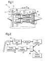
- An exemplary embodiment of the present invention comprises a gas turbine engine 10 as shown in Figure 1 .
- the engine 10 comprises an air intake 12 and a propulsive fan 14 that generates two airflows A and B.
- the gas turbine engine 10 further comprises, in axial flow A, an intermediate pressure compressor 16, a high pressure compressor 18, a combustor or combustion equipment 20, a high pressure turbine 22, an intermediate pressure turbine 24, a low pressure turbine 26 and an exhaust nozzle 28.
- a fan case 30 surrounds the gas turbine engine 10 and defines, in axial flow B, a bypass duct 32.
- engine control means 34 mounted to the outside of the fan case 30 , for example an engine electronic controller (EEC).
- the engine control means 34 comprises an engine monitoring unit (EMU).
- the engine control means 34 comprises a dynamic pressure transducer 36, which is integral with the engine control means 34 but alternatively may be connected thereto.
- a pipe 38 connects the transducer 36 to a location in the engine 10 that is upstream of the combustor 20 and which is subject to pressure fluctuations caused by combustor rumble, for example at the exit of the high pressure compressor 18.
- the transducer 36 is preferably a dynamic pressure transducer that is already provided on the engine 10 for other purposes of control and / or monitoring. This reduces the weight, cost and complexity of the engine 10 by using one component for more than one purpose.
- a P30 (high pressure compressor exit) pressure sensor can perform the functions of transducer 36.
- the pipe 38 is designed to have minimal length and as few bends as possible to reduce weight, avoid signal attenuation and avoid trapping water at bends, which block the pressure fluctuations from being transferred through the pipe 38, although drainage holes may be provided at the bends.
- FIG. 2 A first embodiment of the apparatus and method according to the present invention is shown in Figure 2 .
- the pipe 38 is shown that passes the pressure fluctuations from the engine location, such as at the exit to the high pressure compressor 18, to the dynamic pressure transducer 36 which is located remotely from the combustor 20.
- the signal generated by the transducer 36 is then passed to signal processing means 40 to process the signal to indicate when combustor rumble is occurring.
- the signal received at the transducer 36 may be analogue, in which case the signal is passed to a filter 42, preferably a band pass filter, to extract the frequencies that relate to combustor rumble. From the filter 42 the signal is passed through a calculation block 44 that calculates the root mean square value of the signal.
- the transducer 36 measures the pressure fluctuations at predetermined time intervals. In the case of a piezoelectric transducer, the frequency of measurements is high but for other types of transducer 36 the frequency may be lower. This can be chosen to suit the application.
- a set of digitised signals are provided, separated by small time intervals. Where one of the digitised signals is greater than the rumble threshold 50, the comparator 48 passes a signal that rumble is detected to a fault integrator 52. Conversely, where one of the digitised signals is less than the rumble threshold 50, the comparator 48 passes a signal to that effect to the fault integrator 52.
- the fault integrator 52 is in the form of a counter, which is scaled to count between 0 and 1 in increments of N 'up counts' and M 'down counts'.
- the counter increases by an increment 1/N.
- the counter decreases by an increment 1/M.
- the counter reaches 0 it sets the rumble detection flag 54 to false which is passed to the control and / or monitoring functions.
- any mitigating action is cancelled and further engine health monitoring data can be logged.
- fault integrator 52 in the form of a counter with multiple increments, false triggering of rumble mitigation actions is prevented or reduced and combustor rumble is confirmed prior to action being commanded.
- the multiple increments introduce a small delay between the first detection of combustor rumble, or of cessation of rumble, and commanding action in response.
- FIG. 3 shows a second embodiment of the apparatus and method of the present invention, in which the transducer 36 measures pressure fluctuations and provides a digital output.
- the filter 40, root mean square calculation block 44 and analogue to digital converter 46 are not required.
- the signal processing means 40 comprises a fast Fourier transform function 56. This function 56 not only processes the signal but samples it so that the digitised, sampled signal can be passed to the comparator 48.
- the comparator 48 and fault integrator 52 function in the same manner as in the first embodiment.
- the signal processing means 40 for the digital transducer signal has been proposed as a fast Fourier transform function, alternative digital signal processing is contemplated to fall within the scope of the present invention.
- a different type of filter 42 may be used, for example a low pass filter.
- the fault integrator 52 may be omitted so that the rumble detection flag 54 is set immediately the digitised signal received by the comparator 48 exceeds the rumble threshold 50.
- the fault integrator 52 may take a different form to the described counter.
- the pipe 38 may connect the transducer 36 to a different location in the engine 10 that is upstream of the combustor or combustion equipment 20, for example the exit of the intermediate pressure compressor 16 or the rear of the propulsive fan 14.
- any conduit or other enclosed volume that is capable of passing pressure fluctuations from the location in the engine 10 to the transducer 36 may be substituted with equal felicity.
- the apparatus and method may equally be applied to an industrial or marine gas turbine engine.
- a ducted fan gas turbine engine has been described by way of illustration, a turbojet or unducted fan gas turbine engine may also benefit from the application of the present invention.
- lean burn combustion equipment is more susceptible to combustor rumble than conventional combustion equipment, the present invention is also applicable to gas turbine engines having such combustion equipment.
- the signals generated by the transducer 36 may be processed to provide detection of core damage, particularly high pressure compressor 18 damage.
Landscapes
- Engineering & Computer Science (AREA)
- Chemical & Material Sciences (AREA)
- Combustion & Propulsion (AREA)
- Mechanical Engineering (AREA)
- General Engineering & Computer Science (AREA)
- Control Of Turbines (AREA)
- Regulation And Control Of Combustion (AREA)
Abstract
Apparatus and a method of detecting combustor rumble in a gas turbine engine (10) having combustion equipment that is susceptible to combustor rumble. The method has steps of:
locating a dynamic pressure transducer (36) remotely from the combustion equipment;
connecting a conduit (38) between the transducer and a location in the engine remote from the combustion equipment and subject to pressure fluctuations due to the combustor rumble; and
measuring the pressure fluctuations using the transducer (36) to detect combustor rumble.
Description
- The present invention relates to apparatus and a method for detecting combustor rumble in a gas turbine engine. It is applicable to a gas turbine engine having lean burn combustion equipment. It is particularly, though not exclusively, applicable to an aero gas turbine engine.
- The environmental drive to reduce emissions from gas turbine engines, particularly for use to propel aircraft, leads to a need to use lean burn combustion equipment to eliminate fuel-rich pockets within the combustor. This means the reduction of the air to fuel ratio, in some cases to the extent that the temperature in the combustor falls below the stoichiometric level, which generates problems with flame stability. At lean air to fuel ratios a slight change in the ratio results in a large change in heat release. Hence the heat exchange reaction in the combustor is unsteady and that drives pressure and velocity fluctuations. These fluctuations manifest as an audible rumbling sound known as combustor rumble, being thermo-acoustic oscillations at discrete frequencies. Combustor rumble may cause fatigue failure of components in the engine and / or may cause passenger discomfort, depending on the frequency of the rumbling. There is a need to detect combustor rumble so that control can be applied to cancel it out to reduce or negate its negative effects.
- Industrial gas turbine engines have formerly had more restrictive emissions targets than aero gas turbine engines and have, therefore, used lean burn technology for longer. A typical lean burn industrial gas turbine engine has a rumble probe mounted onto the outer combustor casing in order to detect combustor rumble. Electrical signals generated by the probe are then passed to engine control means, which attempts to control the rumble. The rumble probe typically comprises a dedicated dynamic pressure sensor, such as a piezoelectric transducer. Such a rumble probe mounted to the combustor casing of a conventional industrial gas turbine engine experiences temperatures of around 700K (450°C) and must be able to withstand prolonged periods subjected to this environment.
- One problem with applying the prior art rumble probe to an aero gas turbine engine is that the combustor casing of such an engine is a considerably harsher environment, experiencing temperatures of around 950K (700°C). Currently available dynamic pressure transducers are not reliable at such elevated temperatures, which would instil unacceptable variability and uncertainty into combustor rumble detection if used. The transducers are also prohibitively expensive.
- A further problem is that the weight of the engine is increased by the addition of a rumble probe. It is probable that two rumble probes would be required to provide redundancy, which further adds to the weight and cost of the engine. Additional complexity is also introduced, both to the engine hardware and to the control system.
- The present invention seeks to provide apparatus and a method for combustor rumble detection that seeks to address the aforementioned problems.
- Accordingly the present invention provides a gas turbine engine comprising combustion equipment susceptible to combustor rumble; a dynamic pressure transducer located remotely from the combustion equipment; and a conduit connecting the transducer with a location in the engine remote from the combustion equipment, the location subject to pressure fluctuations due to the combustor rumble; whereby the transducer is arranged to detect combustor rumble dependent on the pressure fluctuations received.
- This is beneficial in terms of weight reduction and accuracy of measurement.
- The combustion equipment may be a lean burn combustor.
- The gas turbine engine may further comprise signal processing means. When the transducer generates an analogue signal, the signal processing means may comprise a filter, preferably a band pass filter. When the transducer generates a digital signal, the signal processing means may comprise a fast Fourier transform. The signal processing means may comprise a rumble threshold comparator. It may comprise a fault integrator, particularly an incremental counter.
- The transducer may be an air pressure sensor.
- The location in the engine remote from the combustion equipment may be at the exit of a compressor stage or at the exit of a propulsive fan.
- The transducer may be arranged to detect core engine damage, particularly high pressure compressor damage, in addition to detecting combustor rumble.
- A second aspect of the present invention provides a method of detecting combustor rumble in a gas turbine engine comprising the steps of:
- locating a dynamic pressure transducer remotely from combustion equipment susceptible to combustor rumble;
- connecting a conduit between the transducer and a location in the engine remote from the combustion equipment and subject to pressure fluctuations due to the combustor rumble; and
- measuring the pressure fluctuations using the transducer to detect combustor rumble.
- This is advantageous because the dynamic pressure transducer is subjected to a less harsh environment by being located remotely from the combustion equipment.
- There may be a further step of processing the signal measured by the transducer, preferably by filtering the signal, by applying a root mean square calculation to the signal or by applying a fast Fourier transform to the signal. The processing step may comprise comparing the signal to a rumble threshold.
- There may be a further step of applying fault integration to the signal, such as by increasing a counter by an increment for each signal above a rumble threshold and decreasing the counter by an increment for each signal below the threshold.
- There may be a further step of setting a rumble detection flag depending on the measured pressure fluctuations.
- The measured pressure fluctuations or the rumble detection flag setting may be passed to an engine control means.
- The signal may be processed to detect core engine damage, particularly high pressure compressor damage.
- The present invention will be more fully described by way of example with reference to the accompanying drawings, in which:
-
Figure 1 is a sectional side view of a gas turbine engine according to the present invention. -
Figure 2 is a block diagram of a first embodiment of the present invention. -
Figure 3 is a block diagram of a second embodiment of the present invention. - An exemplary embodiment of the present invention comprises a
gas turbine engine 10 as shown inFigure 1 . Theengine 10 comprises anair intake 12 and apropulsive fan 14 that generates two airflows A and B. Thegas turbine engine 10 further comprises, in axial flow A, anintermediate pressure compressor 16, ahigh pressure compressor 18, a combustor orcombustion equipment 20, ahigh pressure turbine 22, anintermediate pressure turbine 24, alow pressure turbine 26 and anexhaust nozzle 28. Afan case 30 surrounds thegas turbine engine 10 and defines, in axial flow B, abypass duct 32. - Mounted to the outside of the
fan case 30 is engine control means 34, for example an engine electronic controller (EEC). Alternatively, the engine control means 34 comprises an engine monitoring unit (EMU). The engine control means 34 comprises adynamic pressure transducer 36, which is integral with the engine control means 34 but alternatively may be connected thereto. Apipe 38 connects thetransducer 36 to a location in theengine 10 that is upstream of thecombustor 20 and which is subject to pressure fluctuations caused by combustor rumble, for example at the exit of thehigh pressure compressor 18. Thetransducer 36 is preferably a dynamic pressure transducer that is already provided on theengine 10 for other purposes of control and / or monitoring. This reduces the weight, cost and complexity of theengine 10 by using one component for more than one purpose. For example, a P30 (high pressure compressor exit) pressure sensor can perform the functions oftransducer 36. Thepipe 38 is designed to have minimal length and as few bends as possible to reduce weight, avoid signal attenuation and avoid trapping water at bends, which block the pressure fluctuations from being transferred through thepipe 38, although drainage holes may be provided at the bends. - A first embodiment of the apparatus and method according to the present invention is shown in
Figure 2 . Thepipe 38 is shown that passes the pressure fluctuations from the engine location, such as at the exit to thehigh pressure compressor 18, to thedynamic pressure transducer 36 which is located remotely from thecombustor 20. The signal generated by thetransducer 36 is then passed to signal processing means 40 to process the signal to indicate when combustor rumble is occurring. The signal received at thetransducer 36 may be analogue, in which case the signal is passed to afilter 42, preferably a band pass filter, to extract the frequencies that relate to combustor rumble. From thefilter 42 the signal is passed through acalculation block 44 that calculates the root mean square value of the signal. This value is then sampled by an analogue todigital converter 46 to digitise the signal. The digitised signal is passed to acomparator 48, which also receives arumble threshold 50. Therumble threshold 50 may be an absolute value or may be variable depending upon the point in the flight cycle, aircraft altitude, engine speed or any other factors that affect the pressure and absolute fuel flow in theengine 10. Thetransducer 36 measures the pressure fluctuations at predetermined time intervals. In the case of a piezoelectric transducer, the frequency of measurements is high but for other types oftransducer 36 the frequency may be lower. This can be chosen to suit the application. - Hence a set of digitised signals are provided, separated by small time intervals. Where one of the digitised signals is greater than the
rumble threshold 50, thecomparator 48 passes a signal that rumble is detected to afault integrator 52. Conversely, where one of the digitised signals is less than therumble threshold 50, thecomparator 48 passes a signal to that effect to thefault integrator 52. - The
fault integrator 52 is in the form of a counter, which is scaled to count between 0 and 1 in increments of N 'up counts' and M 'down counts'. Thus, when a rumble detected signal is passed to thefault integrator 52 the counter increases by an increment 1/N. When the counter reaches 1 this sets therumble detection flag 54 to true which is then passed to control and / or monitoring functions, for example in the engine control means 34, for mitigating action to be triggered and engine health monitoring data to be logged. When a signal indicating no rumble is received by thefault integrator 52, the counter decreases by an increment 1/M. When the counter reaches 0 it sets therumble detection flag 54 to false which is passed to the control and / or monitoring functions. Thus, any mitigating action is cancelled and further engine health monitoring data can be logged. - By providing the
fault integrator 52 in the form of a counter with multiple increments, false triggering of rumble mitigation actions is prevented or reduced and combustor rumble is confirmed prior to action being commanded. The multiple increments introduce a small delay between the first detection of combustor rumble, or of cessation of rumble, and commanding action in response. - A variation on the first embodiment is shown in
Figure 3 , which shows a second embodiment of the apparatus and method of the present invention, in which thetransducer 36 measures pressure fluctuations and provides a digital output. In this case thefilter 40, root meansquare calculation block 44 and analogue todigital converter 46 are not required. In their place the signal processing means 40 comprises a fastFourier transform function 56. Thisfunction 56 not only processes the signal but samples it so that the digitised, sampled signal can be passed to thecomparator 48. Thecomparator 48 andfault integrator 52 function in the same manner as in the first embodiment. - Although specific embodiments of the apparatus and method according to the present invention have been described, variations and modifications are possible within the scope of the invention as defined in the accompanying claims. For example, although the signal processing means 40 for the digital transducer signal has been proposed as a fast Fourier transform function, alternative digital signal processing is contemplated to fall within the scope of the present invention. For analogue signals produced by the
transducer 36, a different type offilter 42 may be used, for example a low pass filter. - The
fault integrator 52 may be omitted so that therumble detection flag 54 is set immediately the digitised signal received by thecomparator 48 exceeds therumble threshold 50. Thefault integrator 52 may take a different form to the described counter. - The
pipe 38 may connect thetransducer 36 to a different location in theengine 10 that is upstream of the combustor orcombustion equipment 20, for example the exit of theintermediate pressure compressor 16 or the rear of thepropulsive fan 14. Instead of thepipe 38 that has been described, any conduit or other enclosed volume that is capable of passing pressure fluctuations from the location in theengine 10 to thetransducer 36 may be substituted with equal felicity. - Although the present invention has been described with respect to an aero gas turbine engine, the apparatus and method may equally be applied to an industrial or marine gas turbine engine. Similarly, although a ducted fan gas turbine engine has been described by way of illustration, a turbojet or unducted fan gas turbine engine may also benefit from the application of the present invention. Although lean burn combustion equipment is more susceptible to combustor rumble than conventional combustion equipment, the present invention is also applicable to gas turbine engines having such combustion equipment.
- Although the present invention has been discussed in relation to the detection of combustor rumble, the signals generated by the
transducer 36 may be processed to provide detection of core damage, particularlyhigh pressure compressor 18 damage.
Claims (16)
- A gas turbine engine (10) comprising• combustion equipment (20) susceptible to combustor rumble;• a dynamic pressure transducer (36) located remotely from the combustion equipment (20); and• a conduit (38) connecting the transducer (36) with a location in the engine remote from the combustion equipment (20), the location subject to pressure fluctuations due to the combustor rumble;whereby the transducer (36) is arranged to detect combustor rumble dependent on the pressure fluctuations received.
- A gas turbine engine (10) as claimed in claim 1 further comprising signal processing means (40).
- A gas turbine engine (10) as claimed in claim 2 wherein, when the transducer (36) generates an analogue signal, the signal processing means comprises a filter (42), particularly a band pass filter (42).
- A gas turbine engine (10) as claimed in claim 2 wherein, when the transducer (36) generates a digital signal, the signal processing means (40) comprises a fast Fourier transform (56).
- A gas turbine engine (10) as claimed in any of claims 2 to 4 wherein the signal processing means (40) comprises a rumble threshold comparator (48).
- A gas turbine engine (10) as claimed in any of claims 2 to 5 wherein the signal processing means (40) comprises a fault integrator (52).
- A gas turbine engine (10) as claimed in claim 6 wherein the fault integrator (52) is an incremental counter.
- A gas turbine engine (10) as claimed in any preceding claim wherein the transducer (36) is an air pressure sensor.
- A gas turbine engine (10) as claimed in any preceding claim wherein the location in the engine remote from the combustion equipment (20) is at the exit of a compressor stage (16, 18) or the exit of a propulsive fan (14).
- A method of detecting combustor rumble in a gas turbine engine (10) comprising the steps of:• locating a dynamic pressure transducer (36) remotely from combustion equipment (20) susceptible to combustor rumble;• connecting a conduit (38) between the transducer (36) and a location in the engine remote from the combustion equipment (20) and subject to pressure fluctuations due to the combustor rumble; and• measuring the pressure fluctuations using the transducer (36) to detect combustor rumble.
- A method as claimed in claim 10 comprising the further step of processing the signal measured by the transducer (36).
- A method as claimed in claim 11 wherein the further step of processing the signal comprises at least one of filtering the signal, applying a root mean square calculation to the signal, applying a fast Fourier transform (56) to the signal and comparing the signal to a rumble threshold (50).
- A method as claimed in any of claims 11 to 12 comprising the further step of applying fault integration to the signal.
- A method as claimed in claim 13 wherein the further step of applying fault integration comprises increasing a counter by an increment for each signal above a rumble threshold (50) and decreasing the counter by an increment for each signal below the threshold (50).
- A method as claimed in any of claims 10 to 14 comprising the further step of setting a rumble detection flag (54) depending on the measured pressure fluctuations.
- A method as claimed in any of claims 10 to 15 comprising the further step of passing the measured pressure fluctuations or the rumble detection flag (54) setting to an engine control means (34).
Applications Claiming Priority (1)
| Application Number | Priority Date | Filing Date | Title |
|---|---|---|---|
| GBGB0823085.6A GB0823085D0 (en) | 2008-12-19 | 2008-12-19 | Combustor Rumble |
Publications (1)
| Publication Number | Publication Date |
|---|---|
| EP2199680A1 true EP2199680A1 (en) | 2010-06-23 |
Family
ID=40343804
Family Applications (1)
| Application Number | Title | Priority Date | Filing Date |
|---|---|---|---|
| EP09252388A Withdrawn EP2199680A1 (en) | 2008-12-19 | 2009-10-08 | Combuster rumble |
Country Status (3)
| Country | Link |
|---|---|
| US (1) | US20100158670A1 (en) |
| EP (1) | EP2199680A1 (en) |
| GB (1) | GB0823085D0 (en) |
Cited By (3)
| Publication number | Priority date | Publication date | Assignee | Title |
|---|---|---|---|---|
| WO2014113210A3 (en) * | 2013-01-16 | 2014-09-12 | Alstom Technology Ltd. | Detecting flashback by monitoring engine-dynamics spikes |
| EP3128238A1 (en) * | 2015-08-05 | 2017-02-08 | Siemens Aktiengesellschaft | Intelligent control of combustion with time series and by-pass filters |
| CN107976318A (en) * | 2016-10-21 | 2018-05-01 | 通用电气公司 | To the dynamic (dynamical) indirect monitoring in aircraft combustion chamber |
Families Citing this family (6)
| Publication number | Priority date | Publication date | Assignee | Title |
|---|---|---|---|---|
| US9062611B2 (en) * | 2011-10-19 | 2015-06-23 | United Technologies Corporation | Split accessory drive system |
| DE102011087599A1 (en) | 2011-12-01 | 2013-06-06 | Rolls-Royce Deutschland Ltd & Co Kg | Pressure measuring device and pressure measuring method for a flow engine |
| FR2991066B1 (en) * | 2012-05-28 | 2015-02-27 | Snecma | INFORMATION PROCESSING SYSTEM FOR MONITORING A COMPLEX SYSTEM |
| DE102015210636A1 (en) * | 2015-06-10 | 2016-12-15 | Rolls-Royce Deutschland Ltd & Co Kg | Measuring device for a turbomachine |
| US11092083B2 (en) | 2017-02-10 | 2021-08-17 | General Electric Company | Pressure sensor assembly for a turbine engine |
| GB202314033D0 (en) | 2023-09-14 | 2023-11-01 | Rolls Royce Plc | Electric drive apparatus |
Citations (4)
| Publication number | Priority date | Publication date | Assignee | Title |
|---|---|---|---|---|
| GB2037993A (en) * | 1978-12-21 | 1980-07-16 | Rolls Royce | Dynamic gas pressure measuring device |
| US5575144A (en) * | 1994-11-28 | 1996-11-19 | General Electric Company | System and method for actively controlling pressure pulses in a gas turbine engine combustor |
| US20040168520A1 (en) * | 2003-02-27 | 2004-09-02 | Gleeson Eamon P. | Dynamic pressure probe holder and method of obtaining a dynamic pressure signal |
| US20060042261A1 (en) * | 2004-08-31 | 2006-03-02 | Taware Avinash V | Methods and apparatus for gas turbine engine lean blowout avoidance |
Family Cites Families (11)
| Publication number | Priority date | Publication date | Assignee | Title |
|---|---|---|---|---|
| US2295538A (en) * | 1940-03-13 | 1942-09-15 | Babcock & Wilcox Co | Steam generator |
| GB8329218D0 (en) * | 1983-11-02 | 1983-12-07 | Ffowcs Williams J E | Reheat combustion system for gas turbine engine |
| US6560967B1 (en) * | 1998-05-29 | 2003-05-13 | Jeffrey Mark Cohen | Method and apparatus for use with a gas fueled combustor |
| DE10059701A1 (en) * | 2000-12-01 | 2002-06-06 | Alstom Switzerland Ltd | Probe for measuring pressure vibrations |
| US20070234730A1 (en) * | 2002-06-28 | 2007-10-11 | Markham James R | Method and apparatus for monitoring combustion instability and other performance deviations in turbine engines and like combustion systems |
| GB0304325D0 (en) * | 2003-02-26 | 2003-04-02 | Rolls Royce Plc | Stall detection and recovery system |
| US7113873B2 (en) * | 2003-11-26 | 2006-09-26 | General Electric Company | Method and system for using eddy current transducers in pressure measurements |
| ITTO20031013A1 (en) * | 2003-12-16 | 2005-06-17 | Ansaldo Energia Spa | THERMO ACOUSTIC INSTABILITY DAMPING SYSTEM IN A COMBUSTOR DEVICE FOR A GAS TURBINE. |
| US7159401B1 (en) * | 2004-12-23 | 2007-01-09 | Kulite Semiconductor Products, Inc. | System for detecting and compensating for aerodynamic instabilities in turbo-jet engines |
| US8342793B2 (en) * | 2007-08-22 | 2013-01-01 | Cleveland Electric Laboratories | Active surge control |
| US7942038B2 (en) * | 2009-01-21 | 2011-05-17 | General Electric Company | Systems and methods of monitoring acoustic pressure to detect a flame condition in a gas turbine |
-
2008
- 2008-12-19 GB GBGB0823085.6A patent/GB0823085D0/en not_active Ceased
-
2009
- 2009-10-08 EP EP09252388A patent/EP2199680A1/en not_active Withdrawn
- 2009-11-09 US US12/614,583 patent/US20100158670A1/en not_active Abandoned
Patent Citations (4)
| Publication number | Priority date | Publication date | Assignee | Title |
|---|---|---|---|---|
| GB2037993A (en) * | 1978-12-21 | 1980-07-16 | Rolls Royce | Dynamic gas pressure measuring device |
| US5575144A (en) * | 1994-11-28 | 1996-11-19 | General Electric Company | System and method for actively controlling pressure pulses in a gas turbine engine combustor |
| US20040168520A1 (en) * | 2003-02-27 | 2004-09-02 | Gleeson Eamon P. | Dynamic pressure probe holder and method of obtaining a dynamic pressure signal |
| US20060042261A1 (en) * | 2004-08-31 | 2006-03-02 | Taware Avinash V | Methods and apparatus for gas turbine engine lean blowout avoidance |
Cited By (7)
| Publication number | Priority date | Publication date | Assignee | Title |
|---|---|---|---|---|
| WO2014113210A3 (en) * | 2013-01-16 | 2014-09-12 | Alstom Technology Ltd. | Detecting flashback by monitoring engine-dynamics spikes |
| US9376963B2 (en) | 2013-01-16 | 2016-06-28 | Alstom Technology Ltd. | Detecting flashback by monitoring engine-dynamic spikes |
| EP3128238A1 (en) * | 2015-08-05 | 2017-02-08 | Siemens Aktiengesellschaft | Intelligent control of combustion with time series and by-pass filters |
| WO2017021268A1 (en) * | 2015-08-05 | 2017-02-09 | Siemens Aktiengesellschaft | Intelligent control of combustion with time series and by-pass filters and corresponding system |
| CN107850306A (en) * | 2015-08-05 | 2018-03-27 | 西门子股份公司 | Combustion Intelligent Control and Corresponding System with Time Series and Bypass Filter |
| JP2018529063A (en) * | 2015-08-05 | 2018-10-04 | シーメンス アクチエンゲゼルシヤフトSiemens Aktiengesellschaft | Intelligent control of combustion using time series and bypass filter and corresponding system |
| CN107976318A (en) * | 2016-10-21 | 2018-05-01 | 通用电气公司 | To the dynamic (dynamical) indirect monitoring in aircraft combustion chamber |
Also Published As
| Publication number | Publication date |
|---|---|
| US20100158670A1 (en) | 2010-06-24 |
| GB0823085D0 (en) | 2009-01-28 |
Similar Documents
| Publication | Publication Date | Title |
|---|---|---|
| EP2199680A1 (en) | Combuster rumble | |
| US9506401B2 (en) | Method of detecting shaft break | |
| US10788399B2 (en) | Apparatus for evaluating turbine engine system stability | |
| US7698942B2 (en) | Turbine engine stall warning system | |
| EP2273168B1 (en) | Valve failure detection | |
| EP3473805B1 (en) | Gas turbine engine drive system health monitoring system and method | |
| US20090112519A1 (en) | Foreign object/domestic object damage assessment | |
| US9228915B2 (en) | Method and system for detecting a flow blockage in a pipe | |
| US10132192B2 (en) | Sensor fault detection method | |
| US10774753B2 (en) | Indirect monitoring of aircraft combustor dynamics | |
| EP3232169B1 (en) | System and method for detecting engine vibration | |
| CN111720218B (en) | Signal response monitoring for turbine engines | |
| RU2476915C2 (en) | Method of diagnosing two-stage turbojet with flow mixing | |
| Cullinane et al. | Gas turbine engine validation instrumentation: measurements, sensors, and needs | |
| US9897431B2 (en) | Edge detector | |
| RU2665142C1 (en) | Method of flight diagnostics of units of turbofan engine with flow mixing | |
| Boyle et al. | DGEN aeropropulsion research turbofan core/combustor-noise measurements: Experiment and modal structure at core-nozzle exit | |
| KR102824507B1 (en) | Calculation of turbine inlet temperature using acoustics |
Legal Events
| Date | Code | Title | Description |
|---|---|---|---|
| PUAI | Public reference made under article 153(3) epc to a published international application that has entered the european phase |
Free format text: ORIGINAL CODE: 0009012 |
|
| AK | Designated contracting states |
Kind code of ref document: A1 Designated state(s): AT BE BG CH CY CZ DE DK EE ES FI FR GB GR HR HU IE IS IT LI LT LU LV MC MK MT NL NO PL PT RO SE SI SK SM TR |
|
| AX | Request for extension of the european patent |
Extension state: AL BA RS |
|
| 17P | Request for examination filed |
Effective date: 20100721 |
|
| 17Q | First examination report despatched |
Effective date: 20140121 |
|
| STAA | Information on the status of an ep patent application or granted ep patent |
Free format text: STATUS: THE APPLICATION IS DEEMED TO BE WITHDRAWN |
|
| 18D | Application deemed to be withdrawn |
Effective date: 20140501 |