EP2199626A1 - Method for joining tubular parts with an internal connection knot - Google Patents
Method for joining tubular parts with an internal connection knot Download PDFInfo
- Publication number
- EP2199626A1 EP2199626A1 EP09386035A EP09386035A EP2199626A1 EP 2199626 A1 EP2199626 A1 EP 2199626A1 EP 09386035 A EP09386035 A EP 09386035A EP 09386035 A EP09386035 A EP 09386035A EP 2199626 A1 EP2199626 A1 EP 2199626A1
- Authority
- EP
- European Patent Office
- Prior art keywords
- shape
- knot
- parts
- connection
- succeeded
- Prior art date
- Legal status (The legal status is an assumption and is not a legal conclusion. Google has not performed a legal analysis and makes no representation as to the accuracy of the status listed.)
- Withdrawn
Links
Images




Classifications
-
- A—HUMAN NECESSITIES
- A47—FURNITURE; DOMESTIC ARTICLES OR APPLIANCES; COFFEE MILLS; SPICE MILLS; SUCTION CLEANERS IN GENERAL
- A47B—TABLES; DESKS; OFFICE FURNITURE; CABINETS; DRAWERS; GENERAL DETAILS OF FURNITURE
- A47B47/00—Cabinets, racks or shelf units, characterised by features related to dismountability or building-up from elements
- A47B47/0008—Three-dimensional corner connectors, the legs thereof being received within hollow, elongated frame members
-
- E—FIXED CONSTRUCTIONS
- E04—BUILDING
- E04B—GENERAL BUILDING CONSTRUCTIONS; WALLS, e.g. PARTITIONS; ROOFS; FLOORS; CEILINGS; INSULATION OR OTHER PROTECTION OF BUILDINGS
- E04B1/00—Constructions in general; Structures which are not restricted either to walls, e.g. partitions, or floors or ceilings or roofs
- E04B1/18—Structures comprising elongated load-supporting parts, e.g. columns, girders, skeletons
- E04B1/19—Three-dimensional [3D] framework structures
-
- F—MECHANICAL ENGINEERING; LIGHTING; HEATING; WEAPONS; BLASTING
- F16—ENGINEERING ELEMENTS AND UNITS; GENERAL MEASURES FOR PRODUCING AND MAINTAINING EFFECTIVE FUNCTIONING OF MACHINES OR INSTALLATIONS; THERMAL INSULATION IN GENERAL
- F16B—DEVICES FOR FASTENING OR SECURING CONSTRUCTIONAL ELEMENTS OR MACHINE PARTS TOGETHER, e.g. NAILS, BOLTS, CIRCLIPS, CLAMPS, CLIPS OR WEDGES; JOINTS OR JOINTING
- F16B12/00—Jointing of furniture or the like, e.g. hidden from exterior
- F16B12/44—Leg joints; Corner joints
- F16B12/52—Metal leg connections
-
- F—MECHANICAL ENGINEERING; LIGHTING; HEATING; WEAPONS; BLASTING
- F16—ENGINEERING ELEMENTS AND UNITS; GENERAL MEASURES FOR PRODUCING AND MAINTAINING EFFECTIVE FUNCTIONING OF MACHINES OR INSTALLATIONS; THERMAL INSULATION IN GENERAL
- F16B—DEVICES FOR FASTENING OR SECURING CONSTRUCTIONAL ELEMENTS OR MACHINE PARTS TOGETHER, e.g. NAILS, BOLTS, CIRCLIPS, CLAMPS, CLIPS OR WEDGES; JOINTS OR JOINTING
- F16B2/00—Friction-grip releasable fastenings
- F16B2/02—Clamps, i.e. with gripping action effected by positive means other than the inherent resistance to deformation of the material of the fastening
- F16B2/04—Clamps, i.e. with gripping action effected by positive means other than the inherent resistance to deformation of the material of the fastening internal, i.e. with spreading action
-
- F—MECHANICAL ENGINEERING; LIGHTING; HEATING; WEAPONS; BLASTING
- F16—ENGINEERING ELEMENTS AND UNITS; GENERAL MEASURES FOR PRODUCING AND MAINTAINING EFFECTIVE FUNCTIONING OF MACHINES OR INSTALLATIONS; THERMAL INSULATION IN GENERAL
- F16B—DEVICES FOR FASTENING OR SECURING CONSTRUCTIONAL ELEMENTS OR MACHINE PARTS TOGETHER, e.g. NAILS, BOLTS, CIRCLIPS, CLAMPS, CLIPS OR WEDGES; JOINTS OR JOINTING
- F16B7/00—Connections of rods or tubes, e.g. of non-circular section, mutually, including resilient connections
- F16B7/04—Clamping or clipping connections
- F16B7/044—Clamping or clipping connections for rods or tubes being in angled relationship
- F16B7/0446—Clamping or clipping connections for rods or tubes being in angled relationship for tubes using the innerside thereof
-
- F—MECHANICAL ENGINEERING; LIGHTING; HEATING; WEAPONS; BLASTING
- F16—ENGINEERING ELEMENTS AND UNITS; GENERAL MEASURES FOR PRODUCING AND MAINTAINING EFFECTIVE FUNCTIONING OF MACHINES OR INSTALLATIONS; THERMAL INSULATION IN GENERAL
- F16B—DEVICES FOR FASTENING OR SECURING CONSTRUCTIONAL ELEMENTS OR MACHINE PARTS TOGETHER, e.g. NAILS, BOLTS, CIRCLIPS, CLAMPS, CLIPS OR WEDGES; JOINTS OR JOINTING
- F16B9/00—Connections of rods or tubular parts to flat surfaces at an angle
- F16B9/02—Detachable connections
Definitions
- the Conjunction - Knot has the characteristic that the assembly is not succeeded through spot welding, is knocked down, since the connection is succeeded through screws (design 3.5, 3.7) and offers perfect accuracy.
- the support points are not apparent, giving a harmonic sequence of the knot with the metal spare parts and offer a perfect aesthetic result without screws and slots (design 3.5, 3.7).
- This method allows the easy connection of the surfaces and tubular spare parts, but also the possibility of connecting anodised tubular spare parts under a perfect technical and aesthetical result.
Landscapes
- Engineering & Computer Science (AREA)
- General Engineering & Computer Science (AREA)
- Mechanical Engineering (AREA)
- Architecture (AREA)
- Physics & Mathematics (AREA)
- Electromagnetism (AREA)
- Civil Engineering (AREA)
- Structural Engineering (AREA)
- Mutual Connection Of Rods And Tubes (AREA)
- Furniture Connections (AREA)
Abstract
The invention relates to a method of connecting metal tubular parts with a connection knot (2) for forming tables, desks and like structures.
The connection knot (2) has a «Y» or «T» shape whereby the legs together with two semi-circular identical parts (6) form spigots for insertion into the tubular parts (4,3). The leg of the connection knot is curved to be screwed to a capping member (1) which in turn is inserted in a further tubular part (8) perpendicular to the plane of the connection knot.
The connection knot (2) has a «Y» or «T» shape whereby the legs together with two semi-circular identical parts (6) form spigots for insertion into the tubular parts (4,3). The leg of the connection knot is curved to be screwed to a capping member (1) which in turn is inserted in a further tubular part (8) perpendicular to the plane of the connection knot.
Description
- The invention refers to the conjunction method concerning metal tubular parts with internal connecting knot in shape «Y» or «T» (design 3.2). The invention is consisted of one part in shape «Y» or «T», two same parts, caps in semicircle shape. All the parts are inter connected and also connected with other tubular spare parts (designs 3.1, 3.3, 3.4, 3.6, 3.8).
- The invention is an innovation in the field of the connection of metal tubular parts for industrial uses (i.e. frames of metal desks or of other industrial products).
- Till now, many different ways are known concerning the connection of metal tubular parts, some of which are based on the method of spot welding but without the possibility of disassembly. Others are based on the method of support through screws, but this method can lead to the screws and the slots to be apparent in the connecting points minimizing the aesthetic result.
- The advantage of the specific invention is that offers an accurate and easy assembly and disassembly of the frame, which can be also knocked down.
Moreover, the Conjunction - Knot, because of the way it is assembled, has its screwing points not apparent, so that the aesthetic result is not affected by the view of screws, slots etc. - The Conjunction - Knot, according to the present invention, has the characteristic that the assembly is not succeeded through spot welding, is knocked down, since the connection is succeeded through screws (design 3.5, 3.7) and offers perfect accuracy. The support points are not apparent, giving a harmonic sequence of the knot with the metal spare parts and offer a perfect aesthetic result without screws and slots (design 3.5, 3.7). This method allows the easy connection of the surfaces and tubular spare parts, but also the possibility of connecting anodised tubular spare parts under a perfect technical and aesthetical result.
- It is offered in multiple colours similar to those of the tubular spare parts, offering chromatic harmony to the synthesis. The Conjunction - Knot in shape «Y» or «T» (design 3.2) can be used in different tube diameters, like conjunction of tubular spare parts, for the frame of desks or tables but for many other industrial constructions as well.
-
Design -
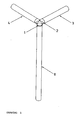
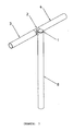
Design 3 presents the axonometric pattern of assembling the above frame. -
Design -
Design -
Design 8 presents the axonometric pattern of assembling the above frame. -
Design - In all the
designs number 1 is a metal spare, which is placed internally to themetal tube number 8. Themetal tube number 8 is the support leg of the desk. - The
number 2 is a part of the knot in shape «Y» or «T». -
Number 6 caps in semicircle shape are the two parts of the knot, which are placed in the bottom of the part in shape «Y» or «T». - Conjunction - Knot in shape «Y» is consisted of: one part in shape «Y» (design 2), two parts of the same, caps, in semicircular shape (design 6) and one part, Base Cap (design 1) in diametric cross section.
- The inter connection is succeeded as following: the part (Base - Cap)
design 1, is placed on the internal cross section of the metal tube (design 8), where is perfectly osculated. It has two holes with screw thread in its cross line part. The same part creates the acumination of the tube (cap). Following, the part in shape «Y» (design 2) is incorporated, placed exactly on the external diameter of the metal tube and screwed internally on the part (Base - Cap) (design 1 and 5). - Following, the two same parts are added (design 6) on the part in shape «Y» (design 2), creating the internal cross section of the metal tube in every side of the angle «Y». After the placement of the metal tubes, the screws are screwed (design 7). These screws have the advantage that are screwed on the part (design 6), against the part (design 2) and as result pushes the part against the metal tube (design 4).
- Based on this method, the steady support of three metal tubes is succeeded with no apparent screws. The synthesis is knocked down and is not permanent or welded. Under the same method, the knot in shape «T» is constructed, while it can be used in tubes of different diameter.
Claims (1)
- The object of the invention is the connection of metal tubular parts with internal connection knot, without spot welding, so that the disassembly will be possible and easy, with accuracy, but also with no apparent connecting spots so that a perfect esthetic result is succeeded.
The connection is succeeded through the use of knot, which is in shape of «Y» or «T» and is consisted of one part in shape of «Y» or «T», two same parts in semicircle shape and one part «Cap - Base». The parts are inter connected in such a way that an accurate and steady connection is succeeded, through screws and slots, which when are added gradually are inter covered and, as a result, are not apparent.
The connection is succeeded through the placement of the part «Cap - Base» in the internal cross section of the vertical tubular part. Then the knot in shape «Y» or «T» is placed on the external diameter of the vertical tube and is screwed to the part Cap-Base. Following, the horizontal tubular parts with the two semicircle parts are incorporated in the two edges of the knot in shape «Y» or «T» and are screwed. The screws penetrate in the internal cross section of the horizontal tubular parts. The result is that there are no apparent spots indicating connection or screwing.
Applications Claiming Priority (1)
| Application Number | Priority Date | Filing Date | Title |
|---|---|---|---|
| GR20080100808A GR1006721B (en) | 2008-12-19 | 2008-12-19 | Connection of metal tubular elements with internal connection node |
Publications (1)
| Publication Number | Publication Date |
|---|---|
| EP2199626A1 true EP2199626A1 (en) | 2010-06-23 |
Family
ID=42084648
Family Applications (1)
| Application Number | Title | Priority Date | Filing Date |
|---|---|---|---|
| EP09386035A Withdrawn EP2199626A1 (en) | 2008-12-19 | 2009-12-09 | Method for joining tubular parts with an internal connection knot |
Country Status (2)
| Country | Link |
|---|---|
| EP (1) | EP2199626A1 (en) |
| GR (1) | GR1006721B (en) |
Cited By (2)
| Publication number | Priority date | Publication date | Assignee | Title |
|---|---|---|---|---|
| USD991023S1 (en) | 2017-12-21 | 2023-07-04 | Lustre Products Ltd. | Modular rail system connector |
| US11739536B2 (en) * | 2017-12-19 | 2023-08-29 | Lustre Products Ltd. | Modular rail system |
Citations (3)
| Publication number | Priority date | Publication date | Assignee | Title |
|---|---|---|---|---|
| FR2310109A1 (en) * | 1975-05-06 | 1976-12-03 | Caimi Export Snc | METAL FRAME FOR FURNITURE, IN PARTICULAR FOR SEATS AND TABLES |
| DE19530780A1 (en) * | 1995-08-22 | 1997-02-27 | Stoll Sedus Ag | System for creating variable table configurations |
| DE29805690U1 (en) * | 1998-03-31 | 1998-06-04 | Christmann & Pfeifer GmbH & Co KG, 35236 Breidenbach | Rack system |
-
2008
- 2008-12-19 GR GR20080100808A patent/GR1006721B/en active IP Right Grant
-
2009
- 2009-12-09 EP EP09386035A patent/EP2199626A1/en not_active Withdrawn
Patent Citations (3)
| Publication number | Priority date | Publication date | Assignee | Title |
|---|---|---|---|---|
| FR2310109A1 (en) * | 1975-05-06 | 1976-12-03 | Caimi Export Snc | METAL FRAME FOR FURNITURE, IN PARTICULAR FOR SEATS AND TABLES |
| DE19530780A1 (en) * | 1995-08-22 | 1997-02-27 | Stoll Sedus Ag | System for creating variable table configurations |
| DE29805690U1 (en) * | 1998-03-31 | 1998-06-04 | Christmann & Pfeifer GmbH & Co KG, 35236 Breidenbach | Rack system |
Cited By (3)
| Publication number | Priority date | Publication date | Assignee | Title |
|---|---|---|---|---|
| US11739536B2 (en) * | 2017-12-19 | 2023-08-29 | Lustre Products Ltd. | Modular rail system |
| US20230374790A1 (en) * | 2017-12-19 | 2023-11-23 | Lustre Products Ltd. | Modular rail system |
| USD991023S1 (en) | 2017-12-21 | 2023-07-04 | Lustre Products Ltd. | Modular rail system connector |
Also Published As
| Publication number | Publication date |
|---|---|
| GR1006721B (en) | 2010-03-09 |
Similar Documents
| Publication | Publication Date | Title |
|---|---|---|
| CN207202490U (en) | A kind of adjustable table of Art Design | |
| EP2199626A1 (en) | Method for joining tubular parts with an internal connection knot | |
| US20140167404A1 (en) | Components for Fabrication of a Stable Base and Support Structure | |
| CN202660180U (en) | Conveniently-detached multi-section household universal bracket | |
| JP3223847U (en) | Single pipe pipe assembly furniture | |
| US20150182019A1 (en) | Bathroom shelf assembly and bathroom shelf having the same | |
| JP6047377B2 (en) | Fixtures | |
| CN210353717U (en) | Table (Ref. Table) | |
| JP6156759B1 (en) | Bundling tool, multi-leg structure and its assembly kit | |
| CN211459955U (en) | Aluminium alloy bathtub support | |
| JP3153599U (en) | Desktop stand device | |
| CN221683336U (en) | Frame connection structure and office furniture | |
| RU28319U1 (en) | Leg for folding furniture | |
| CN203789490U (en) | Book and periodical reading stool | |
| CN201043728Y (en) | Fluorescent lamp holder | |
| CN205298167U (en) | Box fixed knot that screw can be hidden constructs | |
| CN204458706U (en) | A kind of link of Combined desk | |
| CN211092389U (en) | High steadiness table frame | |
| CN201557746U (en) | Table pipe foot fixing element | |
| KR200489115Y1 (en) | Spotlight installation structure using the angled-type support | |
| CN103859845A (en) | Stool for reading books and periodicals | |
| CN201934459U (en) | Table leg connecting member | |
| RU166970U1 (en) | ARMREST | |
| EP2243969A1 (en) | Connection group between a leg and a shelf of a piece of furniture | |
| CN204199565U (en) | A kind of spheroid coupling assembling, syndeton and balustrade |
Legal Events
| Date | Code | Title | Description |
|---|---|---|---|
| PUAI | Public reference made under article 153(3) epc to a published international application that has entered the european phase |
Free format text: ORIGINAL CODE: 0009012 |
|
| AK | Designated contracting states |
Kind code of ref document: A1 Designated state(s): AT BE BG CH CY CZ DE DK EE ES FI FR GB GR HR HU IE IS IT LI LT LU LV MC MK MT NL NO PL PT RO SE SI SK SM TR |
|
| AX | Request for extension of the european patent |
Extension state: AL BA RS |
|
| STAA | Information on the status of an ep patent application or granted ep patent |
Free format text: STATUS: THE APPLICATION IS DEEMED TO BE WITHDRAWN |
|
| 18D | Application deemed to be withdrawn |
Effective date: 20101224 |