EP2199569A1 - System and method for operating a gas turbine using vanadium-containing fuels - Google Patents
System and method for operating a gas turbine using vanadium-containing fuels Download PDFInfo
- Publication number
- EP2199569A1 EP2199569A1 EP09179162A EP09179162A EP2199569A1 EP 2199569 A1 EP2199569 A1 EP 2199569A1 EP 09179162 A EP09179162 A EP 09179162A EP 09179162 A EP09179162 A EP 09179162A EP 2199569 A1 EP2199569 A1 EP 2199569A1
- Authority
- EP
- European Patent Office
- Prior art keywords
- combustion product
- water vapor
- turbine
- vanadium
- combustion
- Prior art date
- Legal status (The legal status is an assumption and is not a legal conclusion. Google has not performed a legal analysis and makes no representation as to the accuracy of the status listed.)
- Withdrawn
Links
- LEONUFNNVUYDNQ-UHFFFAOYSA-N vanadium atom Chemical compound [V] LEONUFNNVUYDNQ-UHFFFAOYSA-N 0.000 title claims abstract description 77
- 229910052720 vanadium Inorganic materials 0.000 title claims abstract description 76
- 238000000034 method Methods 0.000 title claims abstract description 45
- 239000000446 fuel Substances 0.000 title claims abstract description 33
- XLYOFNOQVPJJNP-UHFFFAOYSA-N water Chemical compound O XLYOFNOQVPJJNP-UHFFFAOYSA-N 0.000 claims abstract description 87
- 238000002485 combustion reaction Methods 0.000 claims abstract description 82
- 230000001965 increasing effect Effects 0.000 claims abstract description 26
- 239000007789 gas Substances 0.000 claims description 62
- 229910001868 water Inorganic materials 0.000 claims description 22
- 239000007788 liquid Substances 0.000 claims description 19
- 239000012535 impurity Substances 0.000 claims description 7
- 238000004891 communication Methods 0.000 claims description 6
- 238000009833 condensation Methods 0.000 claims description 6
- 230000005494 condensation Effects 0.000 claims description 6
- 239000012530 fluid Substances 0.000 claims description 6
- 238000010248 power generation Methods 0.000 claims description 5
- 238000010438 heat treatment Methods 0.000 claims description 4
- MYMOFIZGZYHOMD-UHFFFAOYSA-N Dioxygen Chemical compound O=O MYMOFIZGZYHOMD-UHFFFAOYSA-N 0.000 claims description 2
- 239000011734 sodium Substances 0.000 description 41
- 239000000203 mixture Substances 0.000 description 32
- 229910001935 vanadium oxide Inorganic materials 0.000 description 29
- 239000000155 melt Substances 0.000 description 28
- 230000000694 effects Effects 0.000 description 20
- 238000002474 experimental method Methods 0.000 description 16
- GNTDGMZSJNCJKK-UHFFFAOYSA-N divanadium pentaoxide Chemical compound O=[V](=O)O[V](=O)=O GNTDGMZSJNCJKK-UHFFFAOYSA-N 0.000 description 15
- HEMHJVSKTPXQMS-UHFFFAOYSA-M Sodium hydroxide Chemical compound [OH-].[Na+] HEMHJVSKTPXQMS-UHFFFAOYSA-M 0.000 description 12
- 239000007832 Na2SO4 Substances 0.000 description 9
- 238000006243 chemical reaction Methods 0.000 description 9
- 238000001816 cooling Methods 0.000 description 9
- 229910052938 sodium sulfate Inorganic materials 0.000 description 9
- QKDGGEBMABOMMW-UHFFFAOYSA-I [OH-].[OH-].[OH-].[OH-].[OH-].[V+5] Chemical compound [OH-].[OH-].[OH-].[OH-].[OH-].[V+5] QKDGGEBMABOMMW-UHFFFAOYSA-I 0.000 description 7
- 230000004580 weight loss Effects 0.000 description 7
- PMZURENOXWZQFD-UHFFFAOYSA-L Sodium Sulfate Chemical compound [Na+].[Na+].[O-]S([O-])(=O)=O PMZURENOXWZQFD-UHFFFAOYSA-L 0.000 description 6
- CMZUMMUJMWNLFH-UHFFFAOYSA-N sodium metavanadate Chemical compound [Na+].[O-][V](=O)=O CMZUMMUJMWNLFH-UHFFFAOYSA-N 0.000 description 6
- 239000007787 solid Substances 0.000 description 6
- 238000005260 corrosion Methods 0.000 description 5
- 230000007797 corrosion Effects 0.000 description 5
- 238000011067 equilibration Methods 0.000 description 5
- 239000011777 magnesium Substances 0.000 description 5
- 229910052749 magnesium Inorganic materials 0.000 description 5
- LSGOVYNHVSXFFJ-UHFFFAOYSA-N vanadate(3-) Chemical class [O-][V]([O-])([O-])=O LSGOVYNHVSXFFJ-UHFFFAOYSA-N 0.000 description 5
- 230000004584 weight gain Effects 0.000 description 5
- 235000019786 weight gain Nutrition 0.000 description 5
- FYYHWMGAXLPEAU-UHFFFAOYSA-N Magnesium Chemical compound [Mg] FYYHWMGAXLPEAU-UHFFFAOYSA-N 0.000 description 4
- XHCLAFWTIXFWPH-UHFFFAOYSA-N [O-2].[O-2].[O-2].[O-2].[O-2].[V+5].[V+5] Chemical class [O-2].[O-2].[O-2].[O-2].[O-2].[V+5].[V+5] XHCLAFWTIXFWPH-UHFFFAOYSA-N 0.000 description 4
- 239000000567 combustion gas Substances 0.000 description 4
- 230000008021 deposition Effects 0.000 description 4
- 238000000151 deposition Methods 0.000 description 4
- 238000009792 diffusion process Methods 0.000 description 4
- 238000005259 measurement Methods 0.000 description 4
- BASFCYQUMIYNBI-UHFFFAOYSA-N platinum Chemical compound [Pt] BASFCYQUMIYNBI-UHFFFAOYSA-N 0.000 description 4
- 229910000166 zirconium phosphate Inorganic materials 0.000 description 4
- 238000013459 approach Methods 0.000 description 3
- QVGXLLKOCUKJST-UHFFFAOYSA-N atomic oxygen Chemical compound [O] QVGXLLKOCUKJST-UHFFFAOYSA-N 0.000 description 3
- 238000001704 evaporation Methods 0.000 description 3
- 239000011521 glass Substances 0.000 description 3
- 150000004679 hydroxides Chemical class 0.000 description 3
- 238000009533 lab test Methods 0.000 description 3
- 239000001301 oxygen Substances 0.000 description 3
- 229910052760 oxygen Inorganic materials 0.000 description 3
- 150000003682 vanadium compounds Chemical class 0.000 description 3
- 229910019501 NaVO3 Inorganic materials 0.000 description 2
- 239000000654 additive Substances 0.000 description 2
- 238000004458 analytical method Methods 0.000 description 2
- 239000011324 bead Substances 0.000 description 2
- 230000015572 biosynthetic process Effects 0.000 description 2
- 239000012159 carrier gas Substances 0.000 description 2
- 239000003054 catalyst Substances 0.000 description 2
- 238000012937 correction Methods 0.000 description 2
- 230000008020 evaporation Effects 0.000 description 2
- 238000010304 firing Methods 0.000 description 2
- -1 magnesium vanadates Chemical class 0.000 description 2
- 239000000463 material Substances 0.000 description 2
- 229910052697 platinum Inorganic materials 0.000 description 2
- 239000011833 salt mixture Substances 0.000 description 2
- 150000003839 salts Chemical class 0.000 description 2
- 239000000243 solution Substances 0.000 description 2
- 238000012546 transfer Methods 0.000 description 2
- 230000005068 transpiration Effects 0.000 description 2
- 238000009834 vaporization Methods 0.000 description 2
- 230000008016 vaporization Effects 0.000 description 2
- 238000005406 washing Methods 0.000 description 2
- KKCBUQHMOMHUOY-UHFFFAOYSA-N Na2O Inorganic materials [O-2].[Na+].[Na+] KKCBUQHMOMHUOY-UHFFFAOYSA-N 0.000 description 1
- 229910020267 Na2V2O5 Inorganic materials 0.000 description 1
- 229910020522 Na4V2 Inorganic materials 0.000 description 1
- 239000000956 alloy Substances 0.000 description 1
- 229910045601 alloy Inorganic materials 0.000 description 1
- 239000011575 calcium Substances 0.000 description 1
- 229910052791 calcium Inorganic materials 0.000 description 1
- 229940043430 calcium compound Drugs 0.000 description 1
- 150000001674 calcium compounds Chemical class 0.000 description 1
- 230000001627 detrimental effect Effects 0.000 description 1
- 239000010763 heavy fuel oil Substances 0.000 description 1
- 238000002347 injection Methods 0.000 description 1
- 239000007924 injection Substances 0.000 description 1
- 238000004519 manufacturing process Methods 0.000 description 1
- 230000009972 noncorrosive effect Effects 0.000 description 1
- 238000013021 overheating Methods 0.000 description 1
- 230000000737 periodic effect Effects 0.000 description 1
- 239000003208 petroleum Substances 0.000 description 1
- 150000004032 porphyrins Chemical class 0.000 description 1
- 239000010453 quartz Substances 0.000 description 1
- 230000035484 reaction time Effects 0.000 description 1
- VYPSYNLAJGMNEJ-UHFFFAOYSA-N silicon dioxide Inorganic materials O=[Si]=O VYPSYNLAJGMNEJ-UHFFFAOYSA-N 0.000 description 1
- 239000000126 substance Substances 0.000 description 1
- 238000006467 substitution reaction Methods 0.000 description 1
- UUUGYDOQQLOJQA-UHFFFAOYSA-L vanadyl sulfate Chemical compound [V+2]=O.[O-]S([O-])(=O)=O UUUGYDOQQLOJQA-UHFFFAOYSA-L 0.000 description 1
- 229910000352 vanadyl sulfate Inorganic materials 0.000 description 1
- 229940041260 vanadyl sulfate Drugs 0.000 description 1
Images

Classifications
-
- F—MECHANICAL ENGINEERING; LIGHTING; HEATING; WEAPONS; BLASTING
- F02—COMBUSTION ENGINES; HOT-GAS OR COMBUSTION-PRODUCT ENGINE PLANTS
- F02C—GAS-TURBINE PLANTS; AIR INTAKES FOR JET-PROPULSION PLANTS; CONTROLLING FUEL SUPPLY IN AIR-BREATHING JET-PROPULSION PLANTS
- F02C3/00—Gas-turbine plants characterised by the use of combustion products as the working fluid
- F02C3/20—Gas-turbine plants characterised by the use of combustion products as the working fluid using a special fuel, oxidant, or dilution fluid to generate the combustion products
- F02C3/30—Adding water, steam or other fluids for influencing combustion, e.g. to obtain cleaner exhaust gases
-
- F—MECHANICAL ENGINEERING; LIGHTING; HEATING; WEAPONS; BLASTING
- F01—MACHINES OR ENGINES IN GENERAL; ENGINE PLANTS IN GENERAL; STEAM ENGINES
- F01K—STEAM ENGINE PLANTS; STEAM ACCUMULATORS; ENGINE PLANTS NOT OTHERWISE PROVIDED FOR; ENGINES USING SPECIAL WORKING FLUIDS OR CYCLES
- F01K21/00—Steam engine plants not otherwise provided for
- F01K21/04—Steam engine plants not otherwise provided for using mixtures of steam and gas; Plants generating or heating steam by bringing water or steam into direct contact with hot gas
- F01K21/047—Steam engine plants not otherwise provided for using mixtures of steam and gas; Plants generating or heating steam by bringing water or steam into direct contact with hot gas having at least one combustion gas turbine
-
- F—MECHANICAL ENGINEERING; LIGHTING; HEATING; WEAPONS; BLASTING
- F02—COMBUSTION ENGINES; HOT-GAS OR COMBUSTION-PRODUCT ENGINE PLANTS
- F02C—GAS-TURBINE PLANTS; AIR INTAKES FOR JET-PROPULSION PLANTS; CONTROLLING FUEL SUPPLY IN AIR-BREATHING JET-PROPULSION PLANTS
- F02C3/00—Gas-turbine plants characterised by the use of combustion products as the working fluid
- F02C3/20—Gas-turbine plants characterised by the use of combustion products as the working fluid using a special fuel, oxidant, or dilution fluid to generate the combustion products
- F02C3/24—Gas-turbine plants characterised by the use of combustion products as the working fluid using a special fuel, oxidant, or dilution fluid to generate the combustion products the fuel or oxidant being liquid at standard temperature and pressure
Definitions
- An embodiment of the invention relates to the operation of gas turbines. More specifically, embodiments of the invention relate to gas turbines that are operated using heavy fuels that contain vanadium and/or vanadium species.
- Vanadium impurity concentrations in petroleum fuels range from less than 0.5 ppm in distillate fuels to as much as 200 ppm in residual fuels. Corrosion problems associated with liquid vanadium-containing deposits on turbine surfaces limit the use of the cheaper fuels. Present practice is to treat such fuels with magnesium additives which convert the vanadium impurities to solid magnesium vanadates resulting in solid, non-corrosive ash deposits on the blades.
- Non-distillate fuels containing more than 2-3 ppm vanadium by weight can be burned in conventional gas turbines only if magnesium or calcium compounds are added to the fuel to form vanadates during combustion. While the liquid vanadium oxide (V 2 O 5 ) and sodium vanadate (NaVO 3 ) that would otherwise be formed are highly corrosive to gas turbine hot stage materials at moderate temperatures and above, the alkaline earth vanadates (magnesium/calcium vanadates) are solid and result only in deposits within the turbine that are comparatively innocuous from a corrosion standpoint. Solid vanadate-containing deposits can be detrimental to gas turbine operation in other ways, however.
- the deposits decrease aerodynamic efficiency of turbine airfoils, leading to the necessity of periodic removal procedures ("nutshelling" while the turbine is hot, water washing when the turbine is cold). This problem becomes particularly severe for machines with higher firing temperature and high turbine component temperatures where the deposits are hard and difficult to remove by nutshelling and water washing.
- Vanadium occurs in the form of soluble porphyrin complex molecules in fuels, but after combustion it would be present in form of gaseous oxides and hydroxides.
- vanadium oxides have been assumed to be the major vanadium containing species in the gas phase. See, W. D. Halstead, Deposition and Corrosion in Gas Turbines, J. Wiley, 1972, p. 22 ; W. D. Halstead, J. Inst. of Fuel, 42, (1969) 419 ; and N. S. Bornstein and M. A. DeCrescente, "Properties of High Temperature Alloys," The Electrochemical Society, Princeton, 1976, p. 626 .
- An embodiment of the invention for a method of operating a gas turbine that utilizes vanadium-containing fuels.
- a combustion product having vanadium gaseous species is produced and may result in condensation of vanadium depositions on blades of the turbine.
- An embodiment of the invention comprises increasing the vapor pressure of the vanadium gaseous species in the combustion product atmosphere generated in the combustor of the turbine by increasing the water vapor pressure of the combustion product.
- Steam or water vapor may be introduced into the turbine component at location where deposition can occur and cause corrosion of the turbine components; or, the steam/water vapor may be introduced into the combustor.
- the steam/water vapor may be introduced at locations having moving items such as rotary blades and/or stationary components such as nozzles. Introduction of the steam/water vapor at predetermined temperatures and vapor pressures increases the volatility of the vanadium species. More specifically, vanadium oxide (V 2 O 5 ) and sodium vanadate (Na 2 V 2 O 5 ) are oxidized in the presence of the steam/water vapor to form VO(OH) 3 and sodium hydroxide (NaOH) gases, which may not as readily condense on the turbine blades forming the solid vanadium depositions.
- V 2 O 5 vanadium oxide
- Na 2 V 2 O 5 sodium vanadate
- NaOH sodium hydroxide
- An embodiment of the invention may also be described as a gas turbine power generation system that comprises a water vapor source in fluid communication with the turbine element for the introduction of the water vapor into the turbine element and/or combustor to increase a vapor pressure of vanadium gaseous species in the combustion product.
- a water vapor source in fluid communication with the turbine element for the introduction of the water vapor into the turbine element and/or combustor to increase a vapor pressure of vanadium gaseous species in the combustion product.
- increasing water vapor pressure results in an increase of the vanadium gas species vapor pressure, which may reduce the condensation of the vanadium gaseous species on to hot components of the turbine element.
- the system may comprise a closed loop system that takes combustion product and steam (water vapor) exhausted from the turbine element, condenses the gases/vapors into liquid and cleans the liquid, which is then heated and introduced into the turbine element and/or combustor to increase the volatility of the vanadium gaseous species.
- V 2 O 5 and V 4 O 10 The major vanadium containing gaseous oxides under turbine conditions are V 2 O 5 and V 4 O 10 .
- Yannoupoulos observed that the vapor pressure of vanadium hydroxide was very much greater than that of the oxides in O 2 -H 2 O mixtures with P H 2 O greater than about 0.1 atm.
- the vanadium hydroxide vapor pressure would predominate at even lower values of P H 2 O .
- vanadium hydroxide is expected to be the major vanadium containing gaseous species in the first stage region of the turbine where P H 2 O is greater than 0.1 atm.
- V 2 ⁇ O 5 ⁇ l + 3 ⁇ H 2 ⁇ O g 2 ⁇ V ⁇ 0 ⁇ OH 3 g
- P H 2 O water vapor pressure
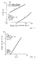
- the graph shows the effect of water vapor on the condensate composition at 900°C.
- the combined sodium vanadate and V 2 O 5 content of the condensate can be reduced from about 36 mole % to about 0.2 mole % by increasing the steam content in the combustion gases from about 3% for normal operation to about 24%.
- FIG. 2 provides a graphic illustration of the effect of water vapor on the allowable fuel level of vanadium (tolerance limit) to maintain the same total concentration of vanadium in the deposit.
- concentration of H 2 O in the gas stream is increased from about 3% to 24%
- concentration of vanadium in the condensate obtained at 900°C from a fuel containing about 23 ppm vanadium (V) would be about the same as that from a fuel containing 1 ppm V for no enrichment in H 2 O.
- the tolerance limit is increased from 1 ppm to 23 ppm under these conditions.
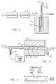
- FIGS. 3 and 4 Two kinds of experimental arrangements shown in FIGS. 3 and 4 were used.
- P H 2 O in the O 2 -H 2 O mixture was controlled by passing O 2 first through a water presaturator 10, maintained at a few degrees above the desired temperature, and then through a saturator 12 filled with glass beads at the desired temperature.
- the glass beads provide a large surface area for equilibration of the gas.
- the entire section of glass tubing between the presaturator and the furnace tube 14 was heated to above 100°C to avoid condensation of H 2 O.
- the O 2 -H 2 O mixture was passed over the salt mixture suspended in a crucible 16 from the arm of a Cahn thermogravimetric balance 18.
- thermocouple 20 was provided to monitor or estimate the temperature of the crucible 16. Measurements of the steady state rate of weight loss from the V 2 O 5 sample provided the vanadium saturation limit of the gas stream. The experiments, however, had some uncertainties due to steep temperature gradients in the furnace tube and relatively poor ( ⁇ 4°c) temperature control.
- the experimental arrangement shown in FIG. 4 was used for volatilization studies on Na 2 V 2 O 6 -Na 2 SO 4 -V 2 O 5 melts.
- the volatilization experiments were carried out in O 2 -SO 2 -SO 3 -H 2 O gas mixtures over a range of water vapor pressures (0-0.83 atm.).
- the required amount of water vapor was obtained using a syringe pump 22 to inject a controlled flow rate of liquid water through a heated thin capillary 24 of about 0.5 mm internal diameter.
- the equilibrium value of P SO 3 was attained by passing the O 2 -SO2-H 2 O gas mixture over a platinum catalyst 26.
- the specimen and catalyst were controlled at the same temperature to within ⁇ 2°C.
- the gas mixture After passing over the melt placed in a platinum crucible 28 in the wider section (12 mm i.d.) of the quartz tube 36 (disposed within a furnace 30), the gas mixture passed through the narrow section (6 mm i.d.) where vanadium oxide and vanadyl sulfate condensed (designated with number 32) on the cooler parts. The cooled gas mixture was finally led through a bubbler 34 to the exhaust. After the experiment was over, the condensate in the cooler parts of the tube was dissolved in dilute HF and analyzed for vanadium content.
- FIG. 5 shows the dependence of vapor density on gas flow rate.
- the curve for P H 2 O 0.045 illustrates typical effects of varying flow rates. At low flow rates, an erroneously high vapor density is obtained because vapor diffusion from the sample to the cooler sections of the tube contributes significantly to the volatilization rates.
- FIG. 5 A plot of the results as a function of P H 2 O is shown in FIG. 5 .
- Table I below gives the results of experiments at 750 and 900°C.
- Table I Volatization Studies with Ns 2 SO 4 -V 2 O 5 -Na 2 V 2 O 6 Gas Mixture P H 2 O Total flow rate at room temp. (cc/min.) Temp.° C Equilibrium P SO 3 Reaction Time (Hours) Total Vanadium Loss (ug) Vapor Density (ug V/litre of gas at STP O 2 + 0.15%SO 2 0.0 50 750 8.7 24 ⁇ 6 ⁇ 0.09 O 2 + 0.2% SO 2 0.21 50 750 8.7 57 145 0.93 O 2 + 0.2% SO 2 0.17 55 750 9.3 66 185 0.92 O 2 + 0.4% SO 2 0.55 50 750 8.7 41 675 6.00 O 2 + 2% SO 2 0.87 50 750 8.7 24 602 9.13 O 2 + 2% SO 2 0.87 50 750 8.7 23.5 625 9.68 O 2 + 0.15%SO 2 0.0 50 900 3.7 48 ⁇ 6 ⁇
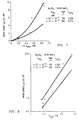
- FIG. 7 there is graphically shown the inferred values of vapor densities as a function of P H 2 O . It is clear that the vapor density of vanadium increases with P H 2 O. Since the vapor density of vanadium should increase with increasing activity of V 2 O 5 (reaction 1), the higher vapor density of vanadium at 750°C than at 900°C (the combustion product temperature may be between about 600°C to about 1100°C) is expected as a result of the higher activity of V 2 O 5 in the melt, as referenced in Table II below.
- the agreement between the experimental vapor density data and the calculated vapor densities using Yannoupoulos' data is extremely good.
- VO(OH) 3 was assumed to be the predominant vanadium containing gaseous species in the presence of steam;
- a log-log plot of the experimental vanadium vapor density ( FIG. 8 ) as a function of P H 2 O shows that the vapor density increases linearly with (P H 2 O ) 1.5 , which is consistent with VO(OH) 3 being the predominant vanadium containing gaseous species.
- FIG. 9 An embodiment of the invention is shown schematically in FIG. 9 .
- V 2 O 5 and Na 2 V 2 O 6 reaching the blade 38 surface will tend to volatilize in the form of vanadium hydroxide and NaOH by reactions (1) and (3):
- Na 2 ⁇ V 2 ⁇ O 6 l + 4 ⁇ H 2 ⁇ O g 2 ⁇ VO ⁇ OH 3 g + 2 ⁇ NaOH g
Landscapes
- Engineering & Computer Science (AREA)
- Chemical & Material Sciences (AREA)
- Combustion & Propulsion (AREA)
- Mechanical Engineering (AREA)
- General Engineering & Computer Science (AREA)
- Inorganic Compounds Of Heavy Metals (AREA)
- Engine Equipment That Uses Special Cycles (AREA)
- Manufacture And Refinement Of Metals (AREA)
Abstract
A method of operating a gas turbine that utilizes vanadium-containing fuels at a combustion stage of the turbine thereby producing a combustion product having vanadium gaseous species, the method comprising increasing the volatility of the vanadium gaseous species in the combustion product atmosphere generated in a combustor of the turbine by increasing concentration of water vapor in the combustion product.
Description
- An embodiment of the invention relates to the operation of gas turbines. More specifically, embodiments of the invention relate to gas turbines that are operated using heavy fuels that contain vanadium and/or vanadium species.
- Vanadium impurity concentrations in petroleum fuels range from less than 0.5 ppm in distillate fuels to as much as 200 ppm in residual fuels. Corrosion problems associated with liquid vanadium-containing deposits on turbine surfaces limit the use of the cheaper fuels. Present practice is to treat such fuels with magnesium additives which convert the vanadium impurities to solid magnesium vanadates resulting in solid, non-corrosive ash deposits on the blades.
- Non-distillate fuels containing more than 2-3 ppm vanadium by weight can be burned in conventional gas turbines only if magnesium or calcium compounds are added to the fuel to form vanadates during combustion. While the liquid vanadium oxide (V2O5) and sodium vanadate (NaVO3) that would otherwise be formed are highly corrosive to gas turbine hot stage materials at moderate temperatures and above, the alkaline earth vanadates (magnesium/calcium vanadates) are solid and result only in deposits within the turbine that are comparatively innocuous from a corrosion standpoint. Solid vanadate-containing deposits can be detrimental to gas turbine operation in other ways, however. First, the deposits decrease aerodynamic efficiency of turbine airfoils, leading to the necessity of periodic removal procedures ("nutshelling" while the turbine is hot, water washing when the turbine is cold). This problem becomes particularly severe for machines with higher firing temperature and high turbine component temperatures where the deposits are hard and difficult to remove by nutshelling and water washing.
- Second, higher efficiency gas turbine with firing temperatures approaching 2300°F depend upon nozzle and bucket cooling by injection of air across the surfaces of these parts (film cooling). Solid vanadate deposits can plug the air cooling ports and lead to overheating of the improperly cooled parts. Thus gas turbines capable of high efficiency operation on clean distillate fuels are generally de-rate for operation on vanadium-containing fuels. Despite these disadvantages, magnesium additives to the fuel are widely used as the only currently feasible approach to utilization of vanadium-containing fuels. No satisfactory method of removing vanadium from fuel prior to combustion has been found. It can be done by setting up or arranging refineries to create distillate fuel which may be complicated and expensive.
- Vanadium occurs in the form of soluble porphyrin complex molecules in fuels, but after combustion it would be present in form of gaseous oxides and hydroxides. In most publications, vanadium oxides have been assumed to be the major vanadium containing species in the gas phase. See, W. D. Halstead, Deposition and Corrosion in Gas Turbines, J. Wiley, 1972, p. 22; W. D. Halstead, J. Inst. of Fuel, 42, (1969) 419; and N. S. Bornstein and M. A. DeCrescente, "Properties of High Temperature Alloys," The Electrochemical Society, Princeton, 1976, p. 626. However, combustion gases in gas turbines contain in excess of 3%
H 20, and at a first stage inlet pressure of greater than 10 atm., the water vapor pressure would be quite significant (> 0.3 atm.) resulting in appreciable concentrations of hydroxides. Volatile hydroxides reported in the literature include V207H4, VO(OH)3, VO(OH)2 and VO2(0H)2. Glemser and Müller determined the vapor pressure of V2O7H4 by transpiration experiments. See, O. Glemser and A. Müller, Z. Anorg. Allgem. Chem., 325, (1963) 220. These workers, however, did not demonstrate that their results were in a flow-rate independent region, a necessary experimental condition for equilibrium measurements. Yannoupoulos (912-1172°K) and Taniguchi and Ooue (738-893°K) reported V0(OH)3 to be the predominant vanadium hydroxide while Suito and Gaskell (1173-1373°K) reported VO(OH)2 and V02(OH)2 to be the major species. See, L. N. Yannoupoulos, J. Phys. Chem., 72, (1968) 3293; M. Taniguchi and M. Ooue, 23rd Annual Conf. of the Chem. Soc. of Japan, 1970 ; and H. Suito and D. R. Gaskell, "Metal-Slag-Gas Reactions and Processes," The Electrochemical Society, Princeton, 1975, p. 251. There is a good agreement between the vapor pressure data of Yannoupoulos and Taniguchi and Ooue; the results of Yannoupoulos have been used for the thermodynamic calculations in this work. - Disclosed herein are embodiments of the invention for a method of operating a gas turbine that utilizes vanadium-containing fuels. At a combustion stage of the turbine a combustion product having vanadium gaseous species is produced and may result in condensation of vanadium depositions on blades of the turbine. An embodiment of the invention comprises increasing the vapor pressure of the vanadium gaseous species in the combustion product atmosphere generated in the combustor of the turbine by increasing the water vapor pressure of the combustion product. Steam or water vapor may be introduced into the turbine component at location where deposition can occur and cause corrosion of the turbine components; or, the steam/water vapor may be introduced into the combustor. The steam/water vapor may be introduced at locations having moving items such as rotary blades and/or stationary components such as nozzles. Introduction of the steam/water vapor at predetermined temperatures and vapor pressures increases the volatility of the vanadium species. More specifically, vanadium oxide (V2O5) and sodium vanadate (Na2V2O5) are oxidized in the presence of the steam/water vapor to form VO(OH)3 and sodium hydroxide (NaOH) gases, which may not as readily condense on the turbine blades forming the solid vanadium depositions.
- An embodiment of the invention may also be described as a gas turbine power generation system that comprises a water vapor source in fluid communication with the turbine element for the introduction of the water vapor into the turbine element and/or combustor to increase a vapor pressure of vanadium gaseous species in the combustion product. As noted above, increasing water vapor pressure results in an increase of the vanadium gas species vapor pressure, which may reduce the condensation of the vanadium gaseous species on to hot components of the turbine element. In an embodiment, the system may comprise a closed loop system that takes combustion product and steam (water vapor) exhausted from the turbine element, condenses the gases/vapors into liquid and cleans the liquid, which is then heated and introduced into the turbine element and/or combustor to increase the volatility of the vanadium gaseous species.
- A more particular description of the invention briefly described above will be rendered by reference to specific embodiments thereof that are illustrated in the appended drawings. Understanding that these drawings depict only typical embodiments of the invention and are not therefore to be considered to be limiting of its scope, the invention will be described and explained with additional specificity and detail through the use of the accompanying drawings:
-
FIG. 1 is a graph illustrating the effect of water vapor concentration on condensate (Na2V2O6-Na2SO4-V2O5) composition. -
FIG. 2 is a graph illustrating effect of water vapor concentration on fuel vanadium tolerance. -
FIG. 3 is a schematic illustration representation of the experimental arrangement used for volatilization studies from pure V2O5. -
FIG. 4 is a schematic illustration representation of the experimental arrangement used for volatilization studies from Na2V2O6-Na2SO4-V2O5 melts. -
FIG. 5 is a graph illustrating effect of flow rate of an O2-H2O gas mixture on the apparent vapor density of V2O5, -
FIG. 6 is a graph illustrating effect of PH2 O in O2-H2O gas mixture on the vapor density of V2O5. -
FIG. 7 is a graph illustrating effect of PH2 O (O2-H20-SO2-SO3 gas mixture) on the volatilization of vanadium from Na2SO4-Na2V2O6-V2O5 melts. -
FIG. 8 is a graph illustrating effect of PH2 O (O2-H20-SO2-SO3 gas mixture) on the volatilization of vanadium from Na2SO4-Na2V2O6-V2O5 melts. -
FIG. 9 is a schematic illustration representation of vanadium volatilization using a steam film cooling process. - A more particular description of the invention briefly described above will be rendered by reference to specific embodiments thereof that are illustrated in the appended drawings. Understanding that these drawings depict only typical embodiments of the invention and are not therefore to be considered to be limiting of its scope, the invention will be described and explained.
- The major vanadium containing gaseous oxides under turbine conditions are V2O5 and V4O10. Yannoupoulos observed that the vapor pressure of vanadium hydroxide was very much greater than that of the oxides in O2-H2O mixtures with PH
2 O greater than about 0.1 atm. At the reduced activities of V2O5 expected in condensates (due to association with Na2O), the vanadium hydroxide vapor pressure would predominate at even lower values of PH2 O. This follows directly from the individual reactions since:
PVO(OH)3 i
is proportional to (aV2 O5 )½, the vapor pressure of vanadium hydroxide (VO(OH)3) is proportional to the square root of vanadium oxide activity (aV2 O5 )x, where x equals 1for V2O5 and 2 for V4O10. Thus, vanadium hydroxide is expected to be the major vanadium containing gaseous species in the first stage region of the turbine where PH2 O is greater than 0.1 atm. - The formation of VO(OH)3 can be described by the reaction:

2 O) would increase the vapor pressure of vanadium compounds and thereby reduce the amount of vanadium in the condensate. Thus, it should be possible to safely use fuels containing higher vanadium impurities by increasing PH2 O in the combustion gases. - Thermodynamic calculations have been conducted by the inventors to support this postulate. With respect to
FIG. 1 , the graph shows the effect of water vapor on the condensate composition at 900°C. For example, for a fuel containing 10 ppm vanadium, the combined sodium vanadate and V2O5 content of the condensate can be reduced from about 36 mole % to about 0.2 mole % by increasing the steam content in the combustion gases from about 3% for normal operation to about 24%. - In addition,
FIG. 2 provides a graphic illustration of the effect of water vapor on the allowable fuel level of vanadium (tolerance limit) to maintain the same total concentration of vanadium in the deposit. For example, if the concentration of H2O in the gas stream is increased from about 3% to 24%, the concentration of vanadium in the condensate obtained at 900°C from a fuel containing about 23 ppm vanadium (V) would be about the same as that from a fuel containing 1 ppm V for no enrichment in H2O. Thus, the tolerance limit is increased from 1 ppm to 23 ppm under these conditions. - Laboratory experiments have been carried out to study the volatilization of vanadium from pure V2O5 and Na2V2O6-V2O5-Na2SO4 mixtures in the presence of steam. The vapor pressure of vanadium compounds was measured by a transpiration technique. When a carrier gas containing H2O vapor is passed over vanadium-containing melts at high temperature, the weight of the salt changes due to a loss of vanadium as result of the formation of vanadium hydroxide. Vanadium compounds condense in the cooler parts of the tube due to a decrease in their volatility at lower temperatures. The vapor density of vanadium in the gas stream can be determined by measuring the weight change of the melt as a function of time or by analyzing for the vanadium content of the condensed material.
- Volatilization of vanadium from pure V2O5 was studied using oxygen as the carrier gas. However, for volatilization experiments over Na2V2O6-Na2SO4 melts, O2-SO2 mixtures providing SO3 levels typical of gas turbine operating conditions were used. The SO2-O2 mixture fixes the equilibrium activity of V2O5 in the melt.
- Two kinds of experimental arrangements shown in
FIGS. 3 and 4 were used. In the arrangement shown inFIG. 3 , PH2 O in the O2-H2O mixture was controlled by passing O2 first through awater presaturator 10, maintained at a few degrees above the desired temperature, and then through asaturator 12 filled with glass beads at the desired temperature. The glass beads provide a large surface area for equilibration of the gas. The entire section of glass tubing between the presaturator and thefurnace tube 14 was heated to above 100°C to avoid condensation of H2O. The O2-H2O mixture was passed over the salt mixture suspended in acrucible 16 from the arm of a Cahnthermogravimetric balance 18. Athermocouple 20 was provided to monitor or estimate the temperature of thecrucible 16. Measurements of the steady state rate of weight loss from the V2O5 sample provided the vanadium saturation limit of the gas stream. The experiments, however, had some uncertainties due to steep temperature gradients in the furnace tube and relatively poor ( ± 4°c) temperature control. - The experimental arrangement shown in
FIG. 4 was used for volatilization studies on Na2V2O6-Na2SO4-V2O5 melts. The volatilization experiments were carried out in O2-SO2-SO3-H2O gas mixtures over a range of water vapor pressures (0-0.83 atm.). The required amount of water vapor was obtained using asyringe pump 22 to inject a controlled flow rate of liquid water through a heatedthin capillary 24 of about 0.5 mm internal diameter. The equilibrium value of PSO3 was attained by passing the O2-SO2-H2O gas mixture over aplatinum catalyst 26. The specimen and catalyst were controlled at the same temperature to within ±2°C. After passing over the melt placed in aplatinum crucible 28 in the wider section (12 mm i.d.) of the quartz tube 36 (disposed within a furnace 30), the gas mixture passed through the narrow section (6 mm i.d.) where vanadium oxide and vanadyl sulfate condensed (designated with number 32) on the cooler parts. The cooled gas mixture was finally led through abubbler 34 to the exhaust. After the experiment was over, the condensate in the cooler parts of the tube was dissolved in dilute HF and analyzed for vanadium content. - Volatilization of vanadium from pure V2O5 was studied at 900°C as a function of gas flow rate and PH
2 OFIG. 5 shows the dependence of vapor density on gas flow rate. Vapor density (v) was obtained from the steady state weight loss rate by the following relation:
2 O = 0.045 illustrates typical effects of varying flow rates. At low flow rates, an erroneously high vapor density is obtained because vapor diffusion from the sample to the cooler sections of the tube contributes significantly to the volatilization rates. At high flow rates, evaporation is too slow to saturate the gas, and an apparently low vapor pressure or vapor density is obtained. The intermediate (plateau) region gives the true equilibrium vapor density. A plot of the results as a function of PH2 O is shown inFIG. 5 . Yannoupoulos observed a vapor density of 65 ug V/litre (STP) for PH2 O = 0.6 at 900°C, which is in reasonably good agreement with the present value (fromFIG. 5 ) of 140 ug V/litre (STP). It can be seen that the vapor density (or the vapor pressure of vanadium containing species) increases almost linearly with PH2 O. However, due to the narrow range over which the vapor density was independent of flow rate (FIG. 5 ), poor control of specimen temperature, and small number of experiments, considerable uncertainty may be associated with the pressure dependence shown. InFIG. 6 . Further volatilization experiments were carried out with Na2SO4-Na2V2O6-V2O5 mixtures because of their greater relevance to turbine operation. - Equilibration Experiments: When a Na2V2O6-Na2SO4 melt is exposed toO2-SO2 environments, the salt gains weight as some of the sodium vanadate is converted to V2O5. Thermodynamic calculations show that the amount of higher order vanadates (Na4V2O7, Na6V2O8) would he small. The equilibrium between the gas mixture and the melt can be expressed as:

- In volatilization experiments, Na2V2O6-Na2SO4 salts were pre-equilibrated with the gas mixture containing the desired level of PSO
3 The equilibrium composition of the condensate was determined from the weight gain of the salt mixture during equilibration. Table I gives the results of experiments at 750°C and 900°C. However, the combustion product temperature may range from about 600°C to about 1100°C. The activity of V2O5 was calculated from the final composition of the melt, assuming activity coefficient values of one for Na2SO4 and Na2V2O6 and using existing thermodynamic data for Na2V2O6, V2O5 and Na2SO4. - Volatilization Studies: A number of factors are important in volatilization studies from multi-component melts such as those containing Na2V2O6, V2O5, and Na2SO4:
- (1) More than one vapor species may have significant vapor pressures; (2) The loss of components at different rates, e.g., the predominant loss of V2O5 from Na2SO4-Na2V2O6-V2O5 mixtures, means that the overall composition of the melt changes with time. This difficulty can be circumvented experimentally by using a large quantity of melt and making measurements over a short time span where the overall composition of the melt stays essentially constant; (2) In the presence of a gas that reacts with the melt, e.g., SO3 with Na2V2O6-Na2SO4-V2O5 melt (as in reaction 2), additional weight changes will result even if the bulk composition of the melt stays nearly constant over the duration of experiment; and, (3) In addition to gas phase mass transport limitations that restrict experiments to a maximum flow rate for gas saturation, mass transfer inside the melt may also affect the vaporization kinetics. If mass transfer in the melt is slow relative to vaporization, composition gradients will arise both from the loss of a component and the ingress of compensating gaseous species. Thus, the activity of the evaporating species at the surface may be different from that corresponding to the bulk composition. This problem can be reduced by carrying out experiments at low flow rates so that the volatilization rates are small, but other limitations may arise; for example, the diffusion of vanadium species away from the sample may be faster than the flow of the bulk gas such that an apparently high vapor density is obtained.
- An attempt was made to measure by weight changes (for the set up shown in
FIG. 3 ) the rate of volatilization from a Na2SO4-Na2V2O6-V2O5 melt in an O2-SO2 environment. The experiments were started with Na2SO4-50 mole % Na2V2O6 (Na2SO4-66.6% mole NaVO3). After an initial period of equilibration with the gas (see reaction 2), the melt experienced a net weight loss which is the result of three major processes which are separate, but related:

- Analysis of the experimental data showed that the melt did not lose weight steadily and that diffusion inside the melt was affecting the process. As a result, the rate of weight change varied with time, and it was not possible to correct accurately for the weight change due to SO3 pickup by the melt. It was concluded that weight change measurements could not be used to obtain meaningful volatilization rates of vanadium from Na2SO4-Na2V2O6-V2O5 melts.
- The experimental arrangement shown in
FIG. 4 was adopted as an alternative. Volatilization rates obtained by chemical analysis of condensates in the cooler section of the tube need no correction for the rate of Na2SO4 loss or weight gain due to SO3 reaction. However, since the rate of volatilization is affected both by flow rate and by the activities of V2O5 and Na2SO4 at the surface, which in turn are affected by gas/melt reactions and by interdiffusion in the melt, a flow-rate- independent region may not be obtained. - Table I below gives the results of experiments at 750 and 900°C.
Table I Volatization Studies with Ns2SO4-V2O5-Na2V2O6 Gas Mixture PH 2 OTotal flow rate at room temp. (cc/min.) Temp.° C Equilibrium PSO 3 Reaction Time (Hours) Total Vanadium Loss (ug) Vapor Density (ug V/litre of gas at STP O2 + 0.15%SO2 0.0 50 750 8.7 24 < 6 < 0.09 O2 + 0.2% SO2 0.21 50 750 8.7 57 145 0.93 O2 + 0.2% SO2 0.17 55 750 9.3 66 185 0.92 O2 + 0.4% SO2 0.55 50 750 8.7 41 675 6.00 O2 + 2% SO2 0.87 50 750 8.7 24 602 9.13 O2 + 2% SO2 0.87 50 750 8.7 23.5 625 9.68 O2 + 0.15%SO2 0.0 50 900 3.7 48 < 6 < 0.05 O2 + 0.2% SO2 0.188 50 900 3.7 50 105 0.76 O2 + 0.2% SO2 0.188 50 900 3.7 41.75 65 0.57 O2 + 0.2% SO2 0.188 100 900 3.7 23.75 82 0.63 O2 + 0.2% SO2 0.188 180 900 3.7 21.75 110 0.51 O2 + 0.4% SO2 0.505 50 900 3.7 22 135 2.24 O2 + 2% SO2 0.84 50 900 3.7 23.25 270 4.23 - Most of the experiments were performed at a total gas flow rate of 50 cc/min. it can be seen from the results at 900°C that under these experimental conditions the gas flow rate had very little effect on volatilization rates.
- With respect to
FIG. 7 there is graphically shown the inferred values of vapor densities as a function of PH2 O. It is clear that the vapor density of vanadium increases with PH2 O. Since the vapor density of vanadium should increase with increasing activity of V2O5 (reaction 1), the higher vapor density of vanadium at 750°C than at 900°C (the combustion product temperature may be between about 600°C to about 1100°C) is expected as a result of the higher activity of V2O5 in the melt, as referenced in Table II below.Table II Equilibration of Na2SO4-50% Na2V2O6 mixtures in O2-0.15% SO2 Temp.°C PSO 3 Weight of starting mixture (mg) Weight gain (mg) Final X Na 2 SO4 Composition X V2O5 X Na2V2O6 Calculated a V2O5 750 8.74 x 10⁻⁴ 199.7 36.7 0.654 0.307 0.04 0.0565 900 3.65 x 10⁻⁴ 462.5 41.0 0.583 0.252 0.252 0.0136 - The agreement between the experimental vapor density data and the calculated vapor densities using Yannoupoulos' data is extremely good. The experimental vapor density at 750°C and PH2O = 0.5 atm. is 4 ug V/litre (STP) compared to a value of 3 ug V/litre (STP) obtained by using Yannoupoulos' data and the activity of V2O5 in table I. Furthermore, for the calculations in
FIGS. 1 and 2 , VO(OH)3 was assumed to be the predominant vanadium containing gaseous species in the presence of steam; a log-log plot of the experimental vanadium vapor density (FIG. 8 ) as a function of PH2 O shows that the vapor density increases linearly with (PH2 O) 1.5, which is consistent with VO(OH)3 being the predominant vanadium containing gaseous species. - The theoretical calculations and laboratory experiments discussed above show that by injecting steam into the combustion product atmosphere it should be possible to increase the volatility of vanadium to allow the use of fuels containing higher vanadium levels. To increase the overall PH
2 O of the combustion gas to effective levels would, however, require unacceptably large quantities of steam. A more practical solution may be to introduce steam locally, where the condensation (and corrosion) problems are encountered. Presently the hot stage components , such as shrouds, blades and vanes of many turbines have air-film cooling. If air cooling is replaced by steam cooling (or air containing steam) a high PH2 O would be attained locally at the surface of the blade, and the condensate would be expected to have a reduced vanadium content. - An embodiment of the invention is shown schematically in
FIG. 9 . V2O5 and Na2V2O6 reaching theblade 38 surface will tend to volatilize in the form of vanadium hydroxide and NaOH by reactions (1) and (3):
- In addition to the vanadium volatilization, steam should give better cooling of the blades in comparison to air because of its higher specific heat and thermal conductivity. This approach appears to be directly applicable to present turbines where the blades or vanes have air-film cooling with an add-on system for steam generation. The laboratory experiments with PH
2 O up to 0.83 atmosphere demonstrate the feasibility of the above approach. - While the preferred embodiments of the present invention have been shown and described herein, it will be obvious that such embodiments are provided by way of example only and not of limitation. Numerous variations, changes and substitutions will occur to those skilled in the art without departing from the teaching of the present invention. For example, if the combustion of the fuel is performed by oxygen or oxygen-enriched air, the concentration and vapor pressure of the water vapor will be higher, and the vanadium tolerance limit will be higher. Accordingly, it is intended that the invention be interpreted within the full scope of the appended claims.
- For completeness, various aspects of the invention are now set out in the following numbered clauses:
- 1. A method of operating a gas turbine that utilizes vanadium-containing fuels at a combustion stage of the turbine thereby producing a combustion product having vanadium gaseous species, the method comprising:
- increasing the volatility of the vanadium gaseous species in the combustion product atmosphere generated in a combustor of the turbine by increasing concentration of water vapor in the combustion product.
- 2. A method of operating a gas turbine that utilizes vanadium-containing fuels at a combustion stage of the turbine thereby producing a combustion product having vanadium gaseous species, the method comprising:
- increasing the vapor pressure of the vanadium gaseous species in a combustion product atmosphere generated in a combustor of the turbine by increasing the water vapor pressure of the combustion product.
- 3. The method of
clause 2, wherein increasing the water vapor includes introducing water vapor to the combustion product at a predetermined temperature and vapor pressure. - 4. The method of
clause 3, wherein the concentration of water in the combustion product is from about 10% to about 50% by volume with the introduction of the water vapor. - 5. The method of
clause 3, wherein the concentration of water in the combustion product may range from about 20% to about 40% by volume with the introduction of the water vapor. - 6. The method of
clause 3, wherein water vapor is introduced to the combustion product at a temperature ranging from about 600°C to about 1100°C. - 7. The method of
clause 6, wherein the concentration of water in the combustion product may range from about 20% to about 40% by volume with the introduction of the water vapor. - 8. The method of
clause 3, wherein water vapor is introduced to the combustion product at a temperature of about 750°C to 1000°C. - 9. The method of
clause 8, wherein the concentration of water in the combustion product may range from about 20% to about 40% by volume with the introduction of the water vapor. - 10. The method of
clause 2, wherein the water vapor pressure of the combustion product is increased directly at a hot stage component such as shroud, vanes, and blades by injecting a water vapor into the turbine element. - 11. The method of
clause 2, wherein the gas turbine includes a combustor for generating the combustion product that is injected into a turbine element and the step of introducing the water vapor includes introducing the water vapor at the combustor before the combustion product reaches the turbine element. - 12. The method of
clause 2, further comprising recovering steam and combustion product from the turbine, condensing the steam and combustion products to liquid form, removing impurities from the liquid form and heating the liquid to form steam that is introduced to combustion product for the turbine that has not been combined with water vapor. - 13. The method of
clause 2, further comprising using a source of liquid oxygen that is injected into a combustor of the gas turbine to produce the combustion product. - 14. The method of clause 13, further comprising recovering steam and combustion product from the turbine, condensing the steam and combustion products to liquid form, removing impurities from the liquid form and heating the liquid to form steam that is introduced to combustion product for the turbine that has not been combined with water vapor.
- 15. The method of
clause 14, wherein the water vapor pressure of the combustion product is increased at a stage where the combustion product is injected into a turbine hot stage component such as rotary blades, shroud or vanes. - 16. The method of
clause 14, wherein the gas turbine includes a combustor for generating the combustion product that is injected into a turbine element and the step of introducing the water vapor includes introducing the water vapor at the combustor before the combustion product reaches the turbine element. - 17. The method of
clause 2, wherein the vanadium limit of the fuel for the gas turbine is increased by a factor of approximately 101.5 by increasing the water vapor concentration by a factor of 10.. - 18. A gas turbine power generation system having a combustor that produces a combustion product that is introduced into a turbine element having a plurality of rotary blades, wherein a vanadium-containing fuel is used at the combustor to produce the combustion product, the system comprising:
- a water vapor source in fluid communication with the turbine power generation system for the introduction of the water vapor to the combustion product to increase a concentration of water vapor in the combustion product and reduce condensation of vanadium gaseous species on to the blades in the turbine element.
- 19. The gas turbine system of
clause 18, wherein the water vapor source is in fluid communication with a combustor for introduction of the water vapor to the combustion product. - 20. The gas turbine system of
clause 18, wherein the water vapor source is in fluid communication with the turbine element such as hot stage component as rotary blades, shrouds or vanes for introduction of the water vapor to the combustion product. - 21. The gas turbine system of
clause 18, wherein the water vapor is introduced to the combustion at some point on the system prior to the combustion product reaching the turbine element. - 22. The gas turbine system of
clause 18, wherein the water vapor source comprises a closed loop system in fluid communication with the turbine element comprising one or more conduits for directing water vapor and combustion products from the turbine element to a condenser to condense the water vapor and production products to liquid, then to a heater to heat the liquid and form water vapor that is introduced into the turbine element.
Claims (15)
- A method of operating a gas turbine that utilizes vanadium-containing fuels at a combustion stage of the turbine thereby producing a combustion product having vanadium gaseous species, the method comprising:increasing the volatility or vapor pressure of the vanadium gaseous species in the combustion product atmosphere generated in a combustor of the turbine by increasing concentration of water vapor or the water vapor pressure in the combustion product.
- The method of claim 1, wherein increasing the water vapor includes introducing water vapor to the combustion product at a predetermined temperature and vapor pressure.
- The method of any preceding claim, wherein the concentration of water in the combustion product is from about 10% to about 50% by volume with the introduction of the water vapor.
- The method of any preceding claim, wherein water vapor is introduced to the combustion product at a temperature ranging from about 600°C to about 1100°C.
- The method of any preceding claim, wherein water vapor is introduced to the combustion product at a temperature of about 750°C to 1000°C.
- The method of any preceding claim, wherein the concentration of water in the combustion product may range from about 20% to about 40% by volume with the introduction of the water vapor.
- The method of any preceding claim, wherein the water vapor pressure of the combustion product is increased directly at a hot stage component such as shroud, vanes, and blades by injecting a water vapor into the turbine element.
- The method of any preceding claim, wherein the gas turbine includes a combustor for generating the combustion product that is injected into a turbine element and the step of introducing the water vapor includes introducing the water vapor at the combustor before the combustion product reaches the turbine element.
- The method of any preceding claim, further comprising recovering steam and combustion product from the turbine, condensing the steam and combustion products to liquid form, removing impurities from the liquid form and heating the liquid to form steam that is introduced to combustion product for the turbine that has not been combined with water vapor.
- The method of any preceding claim, further comprising using a source of liquid oxygen that is injected into a combustor of the gas turbine to produce the combustion product.
- The method of any preceding claim, further comprising recovering steam and combustion product from the turbine, condensing the steam and combustion products to liquid form, removing impurities from the liquid form and heating the liquid to form steam that is introduced to combustion product for the turbine that has not been combined with water vapor.
- The method of any preceding claim, wherein the water vapor pressure of the combustion product is increased at a stage where the combustion product is injected into a turbine hot stage component such as rotary blades, shroud or vanes.
- The method of any preceding claim, wherein the gas turbine includes a combustor for generating the combustion product that is injected into a turbine element and the step of introducing the water vapor includes introducing the water vapor at the combustor before the combustion product reaches the turbine element.
- The method of any preceding claim, wherein the vanadium limit of the fuel for the gas turbine is increased by a factor of approximately 101.5 by increasing the water vapor concentration by a factor of 10..
- A gas turbine power generation system having a combustor that produces a combustion product that is introduced into a turbine element having a plurality of rotary blades, wherein a vanadium-containing fuel is used at the combustor to produce the combustion product, the system comprising:a water vapor source in fluid communication with the turbine power generation system for the introduction of the water vapor to the combustion product to increase a concentration of water vapor in the combustion product and reduce condensation of vanadium gaseous species on to the blades in the turbine element.
Applications Claiming Priority (1)
| Application Number | Priority Date | Filing Date | Title |
|---|---|---|---|
| US12/341,428 US20100154430A1 (en) | 2008-12-22 | 2008-12-22 | System and method for operating a gas turbine using vanadium-containing fuels |
Publications (1)
| Publication Number | Publication Date |
|---|---|
| EP2199569A1 true EP2199569A1 (en) | 2010-06-23 |
Family
ID=42112352
Family Applications (1)
| Application Number | Title | Priority Date | Filing Date |
|---|---|---|---|
| EP09179162A Withdrawn EP2199569A1 (en) | 2008-12-22 | 2009-12-15 | System and method for operating a gas turbine using vanadium-containing fuels |
Country Status (4)
| Country | Link |
|---|---|
| US (1) | US20100154430A1 (en) |
| EP (1) | EP2199569A1 (en) |
| JP (1) | JP2010144728A (en) |
| CN (1) | CN101806248A (en) |
Families Citing this family (3)
| Publication number | Priority date | Publication date | Assignee | Title |
|---|---|---|---|---|
| ITBA20120049A1 (en) * | 2012-07-24 | 2014-01-25 | Itea Spa | COMBUSTION PROCESS |
| ITBA20120048A1 (en) * | 2012-07-24 | 2014-01-25 | Itea Spa | COMBUSTION PROCESS |
| FR3011005B1 (en) * | 2013-09-26 | 2016-08-19 | Ge Energy Products France Snc | MINERAL CLEANING AGENTS IMPLEMENTED IN THE FORM OF SUSPENSIONS |
Citations (5)
| Publication number | Priority date | Publication date | Assignee | Title |
|---|---|---|---|---|
| US3359723A (en) * | 1965-10-29 | 1967-12-26 | Exxon Research Engineering Co | Method of combusting a residual fuel utilizing a two-stage air injection technique and an intermediate steam injection step |
| GB2187273A (en) * | 1985-10-31 | 1987-09-03 | Bernard George Ediss | A gas turbine binary cycle |
| EP1342771A1 (en) * | 2002-03-08 | 2003-09-10 | Hitachi, Ltd. | Process and apparatus for treating heavy oil and power generation system equipped therewith |
| GB2403272A (en) * | 2003-06-28 | 2004-12-29 | Rolls Royce Plc | A gas turbine engine having regulated combustion and steam cooled guide vanes |
| EP1522695A1 (en) * | 1995-10-20 | 2005-04-13 | Arthur T. Griffin, Jr. | Combustor cooling for gas turbine engines |
Family Cites Families (21)
| Publication number | Priority date | Publication date | Assignee | Title |
|---|---|---|---|---|
| US3876363A (en) * | 1974-01-02 | 1975-04-08 | Aqua Chem Inc | Atomizing method and apparatus |
| US4659339A (en) * | 1975-03-31 | 1987-04-21 | Petrolite Corporation | Inhibition of corrosion in fuels with Mg/Al/Si combinations |
| US4545197A (en) * | 1978-10-26 | 1985-10-08 | Rice Ivan G | Process for directing a combustion gas stream onto rotatable blades of a gas turbine |
| US4680927A (en) * | 1979-07-23 | 1987-07-21 | International Power Technology, Inc. | Control system for Cheng dual-fluid cycle engine system |
| US4714032A (en) * | 1985-12-26 | 1987-12-22 | Dipac Associates | Pollution-free pressurized combustion utilizing a controlled concentration of water vapor |
| US5442906A (en) * | 1992-11-30 | 1995-08-22 | Union Oil Company Of California | Combined geothermal and fossil fuel power plant |
| US5312585A (en) * | 1993-06-28 | 1994-05-17 | The United States Of America As Represented By The Secretary Of The Navy | Corrosion inhibition in high temperature environment |
| US5461854A (en) * | 1993-07-07 | 1995-10-31 | Griffin, Jr.; Arthur T. | Combustor cooling for gas turbine engines |
| US5637118A (en) * | 1994-06-30 | 1997-06-10 | United Technologies Corporation | Vanadium corrosion inhibitor |
| AU5662296A (en) * | 1995-03-24 | 1996-10-16 | Ultimate Power Engineering Group, Inc. | High vanadium content fuel combustor and system |
| DE69603640T2 (en) * | 1995-03-31 | 2000-03-16 | United Technologies Corp. | Gas turbine and method for reducing high temperature corrosion in gas turbine parts |
| GB9517646D0 (en) * | 1995-08-30 | 1995-11-01 | Quadrise Ltd | Emulsion fuels and their use in gas turbines |
| JPH1082329A (en) * | 1996-09-09 | 1998-03-31 | Toshiba Corp | Gas turbine equipment |
| JPH1135950A (en) * | 1996-12-26 | 1999-02-09 | Mitsubishi Heavy Ind Ltd | Power generation method and power generation device |
| DE19806823C2 (en) * | 1998-02-18 | 1999-12-09 | Loesche Gmbh | Device and method for the combustion of fuels containing vanadium |
| US6632257B1 (en) * | 1999-05-13 | 2003-10-14 | General Electric Company | Fuel composition and method for extending the time between turbine washes when burning ash bearing fuel in a turbine |
| US6779333B2 (en) * | 2002-05-21 | 2004-08-24 | Conocophillips Company | Dual fuel power generation system |
| AU2003259174A1 (en) * | 2002-07-24 | 2004-02-09 | Mark D. Hughes | Methods and compositions for on-line gas turbine cleaning |
| US6786635B2 (en) * | 2002-11-06 | 2004-09-07 | General Electric Company | Turbine blade (bucket) health monitoring and prognosis using neural network based diagnostic techniques in conjunction with pyrometer signals |
| US7416137B2 (en) * | 2003-01-22 | 2008-08-26 | Vast Power Systems, Inc. | Thermodynamic cycles using thermal diluent |
| US7435330B2 (en) * | 2003-10-07 | 2008-10-14 | Hitachi, Ltd. | Heavy oil reforming method, an apparatus therefor, and gas turbine power generation system |
-
2008
- 2008-12-22 US US12/341,428 patent/US20100154430A1/en not_active Abandoned
-
2009
- 2009-12-15 EP EP09179162A patent/EP2199569A1/en not_active Withdrawn
- 2009-12-17 JP JP2009285849A patent/JP2010144728A/en active Pending
- 2009-12-22 CN CN200910262246A patent/CN101806248A/en active Pending
Patent Citations (5)
| Publication number | Priority date | Publication date | Assignee | Title |
|---|---|---|---|---|
| US3359723A (en) * | 1965-10-29 | 1967-12-26 | Exxon Research Engineering Co | Method of combusting a residual fuel utilizing a two-stage air injection technique and an intermediate steam injection step |
| GB2187273A (en) * | 1985-10-31 | 1987-09-03 | Bernard George Ediss | A gas turbine binary cycle |
| EP1522695A1 (en) * | 1995-10-20 | 2005-04-13 | Arthur T. Griffin, Jr. | Combustor cooling for gas turbine engines |
| EP1342771A1 (en) * | 2002-03-08 | 2003-09-10 | Hitachi, Ltd. | Process and apparatus for treating heavy oil and power generation system equipped therewith |
| GB2403272A (en) * | 2003-06-28 | 2004-12-29 | Rolls Royce Plc | A gas turbine engine having regulated combustion and steam cooled guide vanes |
Also Published As
| Publication number | Publication date |
|---|---|
| CN101806248A (en) | 2010-08-18 |
| US20100154430A1 (en) | 2010-06-24 |
| JP2010144728A (en) | 2010-07-01 |
Similar Documents
| Publication | Publication Date | Title |
|---|---|---|
| Luthra et al. | Impurity deposits in gas turbines from fuels containing sodium and vanadium | |
| KR100742440B1 (en) | How to Prevent Attenuation Loss of Silica and Silicon-Containing Materials in Combustion Gas Environments | |
| Hindiyarti et al. | An exploratory study of alkali sulfate aerosol formation during biomass combustion | |
| CN113544372A (en) | Ammonia decomposition equipment, gas turbine complete equipment equipped with the ammonia decomposition equipment, and ammonia decomposition method | |
| EP2427590B1 (en) | Apparatus and methods for forming modified metal coatings | |
| KR20090060171A (en) | Method for preparing ammonia from urea | |
| EP2199569A1 (en) | System and method for operating a gas turbine using vanadium-containing fuels | |
| SK279647B6 (en) | Condensing sulfuric acid vapors to produce sulfuric acid | |
| CN104995156B (en) | For reducing the method and system that silica subsides in material | |
| Steinbrecher et al. | Stabilization of Solar Salt at 650° C–Thermodynamics and practical implications for thermal energy storage systems | |
| TWI856663B (en) | Process for cracking ammonia | |
| O'Brien et al. | Developments in CVD delivery systems: A chemist's perspective on the chemical and physical interactions between precursors | |
| Ridley et al. | High-temperature water-vapor reaction mechanism of barium strontium aluminosilicate (BSAS) | |
| Myers et al. | Thermochemistry of volatile metal hydroxides and oxyhydroxides at elevated temperatures | |
| Yuan et al. | Exploration of chloride ion impurities on solid-liquid-vapor phase diagram and thermal performance of nitrate molten salts | |
| EP3102307B1 (en) | Device and process for extraction of a chemical compound in acid gases | |
| Holquist et al. | Experimental proof of concept of a cold trap as a purification step for lunar water processing | |
| CN1036706A (en) | In the continuous extraction distillation tower under said muriatic pressure, introduce the method and apparatus of zirconium tetrachloride, hafnium tetrachloride and composition thereof | |
| Zherikova et al. | Towards the MOCVD’s paradise: Thermodynamics of phase transitions of new scandium precursors | |
| Steinberg et al. | The controlling chemistry in flame generated surface deposition of Na2SO4 and the effects of chlorine | |
| Korolev | Deposition of tungsten by reduction of its hexafluoride with hydrogen under the stoichiometric component ratio: an environmentally pure production process | |
| NZ519782A (en) | Method and composition for the prevention of high temperature corrosion due to alkali sulfates and alkali chlorides and composition for use in the same | |
| Nguyen et al. | Experimental and theoretical study of thermodynamics of the reaction of titania and water at high temperatures | |
| CN105424540A (en) | Testing device for volatilization properties of ammonium bisulfate in coal-fired flue gas | |
| Friedman et al. | Burning Velocities. Acetylene and Dideutero-Acetylene with Air. |
Legal Events
| Date | Code | Title | Description |
|---|---|---|---|
| PUAI | Public reference made under article 153(3) epc to a published international application that has entered the european phase |
Free format text: ORIGINAL CODE: 0009012 |
|
| AK | Designated contracting states |
Kind code of ref document: A1 Designated state(s): AT BE BG CH CY CZ DE DK EE ES FI FR GB GR HR HU IE IS IT LI LT LU LV MC MK MT NL NO PL PT RO SE SI SK SM TR |
|
| AX | Request for extension of the european patent |
Extension state: AL BA RS |
|
| 17P | Request for examination filed |
Effective date: 20101223 |
|
| STAA | Information on the status of an ep patent application or granted ep patent |
Free format text: STATUS: THE APPLICATION IS DEEMED TO BE WITHDRAWN |
|
| 18D | Application deemed to be withdrawn |
Effective date: 20140701 |